EP3199060A1 - Bracket assembly - Google Patents
Bracket assembly Download PDFInfo
- Publication number
- EP3199060A1 EP3199060A1 EP16198622.9A EP16198622A EP3199060A1 EP 3199060 A1 EP3199060 A1 EP 3199060A1 EP 16198622 A EP16198622 A EP 16198622A EP 3199060 A1 EP3199060 A1 EP 3199060A1
- Authority
- EP
- European Patent Office
- Prior art keywords
- supporting
- supporting portion
- post
- bracket
- bracket assembly
- Prior art date
- Legal status (The legal status is an assumption and is not a legal conclusion. Google has not performed a legal analysis and makes no representation as to the accuracy of the status listed.)
- Granted
Links
Images





Classifications
-
- A—HUMAN NECESSITIES
- A47—FURNITURE; DOMESTIC ARTICLES OR APPLIANCES; COFFEE MILLS; SPICE MILLS; SUCTION CLEANERS IN GENERAL
- A47B—TABLES; DESKS; OFFICE FURNITURE; CABINETS; DRAWERS; GENERAL DETAILS OF FURNITURE
- A47B88/00—Drawers for tables, cabinets or like furniture; Guides for drawers
- A47B88/40—Sliding drawers; Slides or guides therefor
- A47B88/423—Fastening devices for slides or guides
- A47B88/43—Fastening devices for slides or guides at cabinet side
-
- H—ELECTRICITY
- H05—ELECTRIC TECHNIQUES NOT OTHERWISE PROVIDED FOR
- H05K—PRINTED CIRCUITS; CASINGS OR CONSTRUCTIONAL DETAILS OF ELECTRIC APPARATUS; MANUFACTURE OF ASSEMBLAGES OF ELECTRICAL COMPONENTS
- H05K7/00—Constructional details common to different types of electric apparatus
- H05K7/14—Mounting supporting structure in casing or on frame or rack
- H05K7/1485—Servers; Data center rooms, e.g. 19-inch computer racks
- H05K7/1488—Cabinets therefor, e.g. chassis or racks or mechanical interfaces between blades and support structures
- H05K7/1489—Cabinets therefor, e.g. chassis or racks or mechanical interfaces between blades and support structures characterized by the mounting of blades therein, e.g. brackets, rails, trays
Definitions
- the present invention relates to a bracket assembly and more particularly to one configured to be mounted to a post of a rack.
- a rack-based system includes a slide rail assembly mounted on a rack via a bracket.
- US Patent No. 8,727,138 B2 discloses a toolless rail enabling simplified installation and removal.
- a rail (10) can be mounted to a vertical rack rail (20) through a latch assembly (30), wherein the latch assembly (30) includes two retractable pins (42, 44), two latch arms (52, 54), and two threaded elements (34, 36), all six of which are configured to correspond to and/or be mounted to a plurality of holes (22) of the vertical rack rail (20) respectively.
- the latch assembly (30) includes two retractable pins (42, 44), two latch arms (52, 54), and two threaded elements (34, 36), all six of which are configured to correspond to and/or be mounted to a plurality of holes (22) of the vertical rack rail (20) respectively.
- the holes (22) of the vertical rack rail (20) are larger in size than the two threaded elements (34, 36) (e.g., threaded holes). Therefore, after the two threaded fasteners are respectively inserted into the threaded elements (34, 36), the walls of the corresponding holes (22) of the vertical rack post (20) do not provide physical support for the threaded fasteners, leaving something to be desired in the structural strength of the entire assembly.
- the present invention relates to a bracket assembly configured to be mounted on a post in a well-supported manner.
- a bracket assembly includes a bracket, at least one mounting member, and a supporting member.
- the bracket includes a side plate and an end plate substantially perpendicularly connected to the side plate.
- the at least one mounting member is mounted on the end plate of the bracket.
- the supporting member is also mounted on the end plate of the bracket.
- the bracket device is adapted for mounting a slide rail to a post, and the bracket is mountable on the slide rail, wherein the mounting member is configured to be mounted to a first hole of the post while the supporting member has at least a portion configured to be inserted into a second hole of the post.
- the supporting member includes a first supporting portion, a second supporting portion, and a mounting hole.
- the first supporting portion is larger in size than the second supporting portion.
- the mounting hole is preferably in communication with the first supporting portion and the second supporting portion. The supporting member can be mounted with the post by inserting either one of the first supporting portion and the second supporting portion of the supporting member into the second hole of the post, and a fixing member can be subsequently mounted to the mounting hole to fix the bracket assembly to the post.
- the bracket assembly includes a base mounted on the bracket, and the base provides a receiving space, in which the supporting member is mounted.
- the first supporting portion of the supporting member has a length less than the depth of the receiving space of the base so that the supporting member can be adjusted, or more specifically displaced, with respect to the base.
- the second supporting portion of the supporting member extends from the first supporting portion.
- one of the first supporting portion and the second supporting portion of the supporting member is a circular or rectangular post.
- the mounting hole is a threaded hole configured to lock with the fixing member.
- each slide rail assembly 20 can be used to mount an object 22 to a rack 24. More specifically, each slide rail assembly 20 includes a first rail 26 and a second rail 28, wherein the first rail 26 can be mounted to one of the plural posts 32 of the rack 24 via a bracket assembly 30, and the second rail 28 is configured to carry the object 22 and can be displaced with respect to the first rail 26 in order to enter an extended state.
- first rail 26 can be mounted to one of the plural posts 32 of the rack 24 via a bracket assembly 30, and the second rail 28 is configured to carry the object 22 and can be displaced with respect to the first rail 26 in order to enter an extended state.
- the bracket assembly 30 includes a bracket 34 and at least one supporting member 36.
- the bracket 34 has a side plate 38 and an end plate 40 substantially perpendicularly connected to the side plate 38.
- the end plate 40 has a plurality of end holes 41.
- three supporting members 36 are provided by way of example.
- Each supporting member 36 is mounted on the bracket 34 (e.g., on the end plate 40 of the bracket 34) and partially extends through a corresponding one of the end holes 41 of the end plate 40.
- Each supporting member 36 includes a first supporting portion 42 and a second supporting portion 44, wherein the first supporting portion 42 is larger in size than the second supporting portion 44.
- Each supporting member 36 also has a mounting hole 46, which in this embodiment is in communication with the first supporting portion 42 and the second supporting portion 44.
- the second supporting portion 44 extends a certain distance from the first supporting portion 42, and one of the first supporting portion 42 and the second supporting portion 44 is a circular or rectangular post.
- the first supporting portion 42 of each supporting member 36 is a rectangular post while the second supporting portion 44 of each supporting member 36 is a circular post.
- the first supporting portion 42 and the second supporting portion 44 of each supporting member 36 may both be circular posts or rectangular posts.
- the bracket assembly 30 further includes at least one mounting member 48 and a base 50.
- three mounting members 48 are provided by way of example.
- Each mounting member 48 is mounted on the bracket 34 (e.g., on the end plate 40 of the bracket 34) and extends through a corresponding one of the end holes 41 of the end plate 40.
- the base 50 is also mounted on the bracket 34, and all the mounting members 48 and supporting members 36 are mounted to the end plate 40 of the bracket 34 via the base 50.
- each mounting member 48 includes a first mounting portion 52, a second mounting portion 54, and an elastic member 56 mounted between the first mounting portion 52 and the base 50.
- the second mounting portion 54 is connected to the base 50, and the first mounting portion 52 is larger in size than and is mounted around the second mounting portion 54.
- each supporting member 36 can be adjusted, or more specifically displaced, with respect to the base 50.
- the base 50 provides a receiving space 51 for each supporting member 36, and the supporting members 36 are mounted in the receiving spaces 51 respectively.
- the bracket 34 is mounted on the first rail 26 and in this embodiment is mounted on the first rail 26 via the side plate 38.
- the post 32 has a plurality of holes, which are of the same size and include a plurality of first holes 58a and a plurality of second holes 58b for example.
- the first holes 58a and the second holes 58b are rectangular holes.
- the first mounting portion 52 of each mounting member 48 is slightly smaller in size than the first holes 58a, whereas the first supporting portion 42 of each supporting member 36 is slightly smaller in size than the second holes 58b.
- the bracket 34 is mounted to the post 32 such that the first mounting portions 52 of the mounting members 48 are mounted in the first holes 58a respectively.
- the supporting members 36 are respectively and at least partially inserted into the second holes 58b. In this embodiment, it is the first supporting portion 42 of each supporting member 36 that enters the corresponding second hole 58b.
- a plurality of fixing members 60 are also included and are configured to be mounted to the mounting holes 46 of the supporting members 36 respectively and thereby fix the bracket assembly 30 to the post 32.
- Each mounting hole 46 may be a threaded hole configured to lock with any of the fixing members 60 (e.g., threaded members).
- each mounting hole 46 may be a through hole, and in that case each fixing member 60 is passed partially through the through hole of the corresponding supporting member 36 and then locks with a nut (not shown) to fix the bracket assembly 30 to the post 32.
- the bracket assembly 30 not only is mounted on the post 32 via the three mounting members 48, but also gains additional support through the three supporting members 36, each having at least a portion (e.g., the first supporting portion 42) inserted in the corresponding second hole 58b of the post 32. More specifically, each first supporting portion 42 is confined by the wall (e.g., a rectangular wall) of the corresponding second hole 58b of the post 32 once inserted in the corresponding second hole 58b, and this helps increase the structural strength of the entire assembly composed of the post 32 and the bracket 34 mounted thereon.
- the bracket assembly 30 is further fixed to the post 32, and the bracket 34 is securely held in the upward, downward, leftward, and rightward directions.
- the bracket assembly 30 also can be mounted to a post 200.
- the post 200 has a plurality of holes, which are of the same size and include a plurality of first holes 202 and a plurality of second holes 204 for example.
- the first holes 202 and the second holes 204 are circular holes.
- the second mounting portion 54 of each mounting member 48 is slightly smaller in size than the first holes 202 while the first mounting portion 52 of each mounting member 48 is larger in size than the first holes 202.
- the second supporting portion 44 of each supporting member 36 is lightly smaller in size than the second holes 204 while the first supporting portion 42 of each supporting member 36 is larger in size than the second holes 204.
- each mounting member 48 as shown in FIG. 10 and FIG. 11 , the elastic member 56 applies an elastic force to the first mounting portion 52, and the first mounting portion 52 extends out of the base 50 in response to the elastic force of the elastic member 56.
- the bracket 34 is displaced in a direction D toward the post 200 such that the second mounting portions 54 of the mounting members 48 enter the first holes 202 respectively.
- the first mounting portions 52 of the mounting members 48 are too large to enter the first holes 202 respectively and are therefore pressed against the post 200.
- the second supporting portions 44 of the supporting members 36 are respectively aligned with the second holes 204.
- the first mounting portions 52 of the mounting members 48 are displaced with respect to the second mounting portions 54 in the opposite direction of the direction D thanks to the elastic members 56.
- the elastic members 56 are compressed by the first mounting portions 52 respectively and each store an elastic force while the second mounting portions 54 of the mounting members 48 are mounted into the first holes 202 respectively.
- the supporting members 36 they are at least partially inserted into the second holes 204 respectively, and in this embodiment it is the second supporting portions 44 of the supporting members 36 that are respectively inserted into the second holes 204.
- the first supporting portion 42 of each supporting member 36 has a length L1 less than the depth L2 of each receiving space 51 of the base 50 so that the supporting members 36 can be adjusted, or more specifically displaced, with respect to the base 50.
- the bracket assembly 30 can be further fixed to the post 200 by inserting the fixing members 60 into the mounting holes 46 of the supporting members 36 respectively.
- the bracket assembly 30 not only is mounted on the post 200 via the three mounting members 48, but also gains additional support through the three supporting members 36, each having at least a portion (e.g., the second supporting portion 44) inserted in the corresponding second hole 204 of the post 200. More specifically, each second supporting portion 44 is confined by the wall (e.g., a circular wall) of the corresponding second hole 204 of the post 200 once inserted in the corresponding second hole 204, and this helps increase the structural strength of the entire assembly composed of the post 200 and the bracket 34 mounted thereon.
- the bracket assembly 30 is further locked to the post 200, and the bracket 34 is firmly held in the upward, downward, leftward, and rightward directions.
- implementation of the present invention has the following features: Firstly, the mounting members 48 of the bracket 34 are configured to be inserted into and hence supported by the post 32, 200. Secondly, and more importantly, the supporting members 36 can be inserted respectively and at least partially into the corresponding holes of the post 32, 200 to keep the bracket assembly 30 securely mounted on the post 32, 200. Thirdly, the fixing members 60 can be used to lock the bracket assembly 30 to the post 32, 200, thereby providing additional support to the bracket 34 in the upward, downward, leftward, and rightward directions, rendering the bracket assembly 30 well supported in vibration tests, and ensuring the safety of use of the object 22 (e.g., a chassis) carried by the slide rail assemblies 20. Last but not least, each supporting member 36 has two supporting portions 42, 44 configured to cope with the differently shaped (e.g., rectangular or circular) holes of various posts.
- the differently shaped e.g., rectangular or circular
Landscapes
- Engineering & Computer Science (AREA)
- Computer Hardware Design (AREA)
- General Engineering & Computer Science (AREA)
- Microelectronics & Electronic Packaging (AREA)
- Drawers Of Furniture (AREA)
Abstract
Description
- The present invention relates to a bracket assembly and more particularly to one configured to be mounted to a post of a rack.
- Generally, a rack-based system includes a slide rail assembly mounted on a rack via a bracket.
US Patent No. 8,727,138 B2 , for instance, discloses a toolless rail enabling simplified installation and removal. According toFIG. 1 andFIG. 2 accompanying the specification of this US patent, a rail (10) can be mounted to a vertical rack rail (20) through a latch assembly (30), wherein the latch assembly (30) includes two retractable pins (42, 44), two latch arms (52, 54), and two threaded elements (34, 36), all six of which are configured to correspond to and/or be mounted to a plurality of holes (22) of the vertical rack rail (20) respectively. As shown inFIG. 7A of the specification of the US patent, once the two retractable pins (42, 44) and the two latch arms (52, 54) are mounted in their respective holes (22), two optional threaded fasteners can be used to lock with the two threaded elements (34, 36) respectively, thereby locking the latch assembly (30) to the vertical rack rail (20). - More specifically, as can be known from
FIG. 7A of the specification of the afore-cited patent, the holes (22) of the vertical rack rail (20) are larger in size than the two threaded elements (34, 36) (e.g., threaded holes). Therefore, after the two threaded fasteners are respectively inserted into the threaded elements (34, 36), the walls of the corresponding holes (22) of the vertical rack post (20) do not provide physical support for the threaded fasteners, leaving something to be desired in the structural strength of the entire assembly. - The present invention relates to a bracket assembly configured to be mounted on a post in a well-supported manner.
- According to one aspect of the present invention, a bracket assembly includes a bracket, at least one mounting member, and a supporting member. The bracket includes a side plate and an end plate substantially perpendicularly connected to the side plate. The at least one mounting member is mounted on the end plate of the bracket. The supporting member is also mounted on the end plate of the bracket. Preferably, the bracket device is adapted for mounting a slide rail to a post, and the bracket is mountable on the slide rail, wherein the mounting member is configured to be mounted to a first hole of the post while the supporting member has at least a portion configured to be inserted into a second hole of the post.
- In some embodiments, the supporting member includes a first supporting portion, a second supporting portion, and a mounting hole. The first supporting portion is larger in size than the second supporting portion. The mounting hole is preferably in communication with the first supporting portion and the second supporting portion. The supporting member can be mounted with the post by inserting either one of the first supporting portion and the second supporting portion of the supporting member into the second hole of the post, and a fixing member can be subsequently mounted to the mounting hole to fix the bracket assembly to the post.
- In some embodiments, the bracket assembly includes a base mounted on the bracket, and the base provides a receiving space, in which the supporting member is mounted. The first supporting portion of the supporting member has a length less than the depth of the receiving space of the base so that the supporting member can be adjusted, or more specifically displaced, with respect to the base.
- In some embodiments, the second supporting portion of the supporting member extends from the first supporting portion.
- In some embodiments, one of the first supporting portion and the second supporting portion of the supporting member is a circular or rectangular post.
- In some embodiments, the mounting hole is a threaded hole configured to lock with the fixing member.
-
-
FIG. 1 is a perspective view showing how a pair of slide rail assemblies mount an object to a rack via a pair of bracket assemblies according to an embodiment of the present invention; -
FIG. 2 is an assembled perspective view of the bracket assembly according to an embodiment of the present invention; -
FIG. 3 is an exploded perspective view of the bracket assembly according to an embodiment of the present invention; -
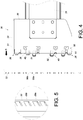
FIG. 4 shows how the bracket assembly according to an embodiment of the present invention is mounted to a post with rectangular holes; -
FIG. 5 is a partial perspective view of the post inFIG. 4 ; -
FIG. 6 shows the bracket assembly according to an embodiment of the present invention mounted on the post inFIG. 4 and also shows how the bracket assembly can be locked to the post by at least one fixing member; -
FIG. 7 is a perspective view showing the bracket assembly according to an embodiment of the present invention mounted on the post inFIG. 4 ; -
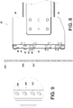
FIG. 8 shows how the bracket assembly according to an embodiment of the present invention is mounted to another post with circular holes; -
FIG. 9 is a partial perspective view of the post inFIG. 8 ; -
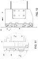
FIG. 10 shows the bracket assembly inFIG. 8 further displaced toward the post; -
FIG. 11 is an enlarged view of the circled area A inFIG. 10 ; -
FIG. 12 shows the bracket assembly according to an embodiment of the present invention mounted on the post inFIG. 8 and also shows how the bracket assembly can be locked to the post by at least one fixing member; -
FIG. 13 is an enlarged view of the circled area B inFIG. 12 ; and -
FIG. 14 is a perspective view showing the bracket assembly according to an embodiment of the present invention mounted on the post inFIG. 8 . - According to an embodiment of the present invention, referring to
FIG. 1 , a pair ofslide rail assemblies 20 can be used to mount anobject 22 to arack 24. More specifically, eachslide rail assembly 20 includes afirst rail 26 and asecond rail 28, wherein thefirst rail 26 can be mounted to one of theplural posts 32 of therack 24 via abracket assembly 30, and thesecond rail 28 is configured to carry theobject 22 and can be displaced with respect to thefirst rail 26 in order to enter an extended state. The foregoing arrangement is well known in the art and therefore will not be further dealt with herein. - As shown in
FIG. 2 andFIG. 3 , thebracket assembly 30 includes abracket 34 and at least one supportingmember 36. Thebracket 34 has aside plate 38 and anend plate 40 substantially perpendicularly connected to theside plate 38. Theend plate 40 has a plurality ofend holes 41. In this embodiment, three supportingmembers 36 are provided by way of example. Each supportingmember 36 is mounted on the bracket 34 (e.g., on theend plate 40 of the bracket 34) and partially extends through a corresponding one of theend holes 41 of theend plate 40. Each supportingmember 36 includes a first supportingportion 42 and a second supportingportion 44, wherein the first supportingportion 42 is larger in size than the second supportingportion 44. Each supportingmember 36 also has amounting hole 46, which in this embodiment is in communication with the first supportingportion 42 and the second supportingportion 44. In each supportingmember 36, the second supportingportion 44 extends a certain distance from the first supportingportion 42, and one of the first supportingportion 42 and the second supportingportion 44 is a circular or rectangular post. In this embodiment by way of example, the first supportingportion 42 of each supportingmember 36 is a rectangular post while the second supportingportion 44 of each supportingmember 36 is a circular post. In other embodiments, however, the first supportingportion 42 and the second supportingportion 44 of each supportingmember 36 may both be circular posts or rectangular posts. - The
bracket assembly 30 further includes at least onemounting member 48 and abase 50. In this embodiment, threemounting members 48 are provided by way of example. Eachmounting member 48 is mounted on the bracket 34 (e.g., on theend plate 40 of the bracket 34) and extends through a corresponding one of theend holes 41 of theend plate 40. Thebase 50 is also mounted on thebracket 34, and all themounting members 48 and supportingmembers 36 are mounted to theend plate 40 of thebracket 34 via thebase 50. Preferably, eachmounting member 48 includes afirst mounting portion 52, asecond mounting portion 54, and anelastic member 56 mounted between thefirst mounting portion 52 and thebase 50. In eachmounting member 48, thesecond mounting portion 54 is connected to thebase 50, and thefirst mounting portion 52 is larger in size than and is mounted around thesecond mounting portion 54. Moreover, each supportingmember 36 can be adjusted, or more specifically displaced, with respect to thebase 50. - Referring to
FIG. 4 and FIG. 5 , thebase 50 provides areceiving space 51 for each supportingmember 36, and the supportingmembers 36 are mounted in thereceiving spaces 51 respectively. Thebracket 34 is mounted on thefirst rail 26 and in this embodiment is mounted on thefirst rail 26 via theside plate 38. Thefirst rail 26, in turn, is mounted on thepost 32 via thebracket 34. Thepost 32 has a plurality of holes, which are of the same size and include a plurality offirst holes 58a and a plurality ofsecond holes 58b for example. Thefirst holes 58a and thesecond holes 58b are rectangular holes. The first mountingportion 52 of each mountingmember 48 is slightly smaller in size than thefirst holes 58a, whereas the first supportingportion 42 of each supportingmember 36 is slightly smaller in size than thesecond holes 58b. - During the mounting process, referring to
FIG. 6 , thebracket 34 is mounted to thepost 32 such that the first mountingportions 52 of the mountingmembers 48 are mounted in thefirst holes 58a respectively. On the other hand, the supportingmembers 36 are respectively and at least partially inserted into thesecond holes 58b. In this embodiment, it is the first supportingportion 42 of each supportingmember 36 that enters the correspondingsecond hole 58b. Preferably, a plurality of fixingmembers 60 are also included and are configured to be mounted to the mountingholes 46 of the supportingmembers 36 respectively and thereby fix thebracket assembly 30 to thepost 32. Each mountinghole 46 may be a threaded hole configured to lock with any of the fixing members 60 (e.g., threaded members). Alternatively, each mountinghole 46 may be a through hole, and in that case each fixingmember 60 is passed partially through the through hole of the corresponding supportingmember 36 and then locks with a nut (not shown) to fix thebracket assembly 30 to thepost 32. - As shown in
FIG. 7 , thebracket assembly 30 not only is mounted on thepost 32 via the three mountingmembers 48, but also gains additional support through the three supportingmembers 36, each having at least a portion (e.g., the first supporting portion 42) inserted in the correspondingsecond hole 58b of thepost 32. More specifically, each first supportingportion 42 is confined by the wall (e.g., a rectangular wall) of the correspondingsecond hole 58b of thepost 32 once inserted in the correspondingsecond hole 58b, and this helps increase the structural strength of the entire assembly composed of thepost 32 and thebracket 34 mounted thereon. By additionally inserting a portion of each fixingmember 60 into the corresponding mountinghole 46, thebracket assembly 30 is further fixed to thepost 32, and thebracket 34 is securely held in the upward, downward, leftward, and rightward directions. - Referring to
FIG. 8 and FIG. 9 , thebracket assembly 30 also can be mounted to apost 200. Thepost 200 has a plurality of holes, which are of the same size and include a plurality offirst holes 202 and a plurality ofsecond holes 204 for example. Thefirst holes 202 and thesecond holes 204 are circular holes. The second mountingportion 54 of each mountingmember 48 is slightly smaller in size than thefirst holes 202 while the first mountingportion 52 of each mountingmember 48 is larger in size than thefirst holes 202. The second supportingportion 44 of each supportingmember 36 is lightly smaller in size than thesecond holes 204 while the first supportingportion 42 of each supportingmember 36 is larger in size than thesecond holes 204. - In each mounting
member 48, as shown inFIG. 10 and FIG. 11 , theelastic member 56 applies an elastic force to the first mountingportion 52, and the first mountingportion 52 extends out of the base 50 in response to the elastic force of theelastic member 56. During the mounting process, thebracket 34 is displaced in a direction D toward thepost 200 such that the second mountingportions 54 of the mountingmembers 48 enter thefirst holes 202 respectively. However, the first mountingportions 52 of the mountingmembers 48 are too large to enter thefirst holes 202 respectively and are therefore pressed against thepost 200. The second supportingportions 44 of the supportingmembers 36, on the other hand, are respectively aligned with thesecond holes 204. - Referring to
FIG. 12 and FIG. 13 , when thebracket assembly 30 is further displaced in the direction D toward thepost 200, the first mountingportions 52 of the mountingmembers 48 are displaced with respect to the second mountingportions 54 in the opposite direction of the direction D thanks to theelastic members 56. Theelastic members 56, in turn, are compressed by the first mountingportions 52 respectively and each store an elastic force while the second mountingportions 54 of the mountingmembers 48 are mounted into thefirst holes 202 respectively. As to the supportingmembers 36, they are at least partially inserted into thesecond holes 204 respectively, and in this embodiment it is the second supportingportions 44 of the supportingmembers 36 that are respectively inserted into thesecond holes 204. Preferably, the first supportingportion 42 of each supportingmember 36 has a length L1 less than the depth L2 of each receivingspace 51 of the base 50 so that the supportingmembers 36 can be adjusted, or more specifically displaced, with respect to thebase 50. Moreover, thebracket assembly 30 can be further fixed to thepost 200 by inserting the fixingmembers 60 into the mountingholes 46 of the supportingmembers 36 respectively. - As shown in
FIG. 12 andFIG. 14 , thebracket assembly 30 not only is mounted on thepost 200 via the three mountingmembers 48, but also gains additional support through the three supportingmembers 36, each having at least a portion (e.g., the second supporting portion 44) inserted in the correspondingsecond hole 204 of thepost 200. More specifically, each second supportingportion 44 is confined by the wall (e.g., a circular wall) of the correspondingsecond hole 204 of thepost 200 once inserted in the correspondingsecond hole 204, and this helps increase the structural strength of the entire assembly composed of thepost 200 and thebracket 34 mounted thereon. By additionally mounting the fixingmembers 60 to the mountingholes 46 respectively, thebracket assembly 30 is further locked to thepost 200, and thebracket 34 is firmly held in the upward, downward, leftward, and rightward directions. - According to the above, implementation of the present invention has the following features: Firstly, the mounting
members 48 of thebracket 34 are configured to be inserted into and hence supported by thepost members 36 can be inserted respectively and at least partially into the corresponding holes of thepost bracket assembly 30 securely mounted on thepost members 60 can be used to lock thebracket assembly 30 to thepost bracket 34 in the upward, downward, leftward, and rightward directions, rendering thebracket assembly 30 well supported in vibration tests, and ensuring the safety of use of the object 22 (e.g., a chassis) carried by theslide rail assemblies 20. Last but not least, each supportingmember 36 has two supportingportions - While the present invention has been disclosed through the foregoing preferred embodiment, it should be understood that the embodiment are not intended to be restrictive of the invention. The scope of patent protection sought by the applicant is defined by the appended claims.
Claims (8)
- A bracket assembly (30), comprising:a bracket (34) including a side plate (38) and an end plate (40) substantially perpendicularly connected to the side plate (38);at least one mounting member (48) mounted on the end plate (40) of the bracket (34);
characterized in thatthe bracket assembly (30) further comprises a supporting member (36) mounted on the end plate (40) of the bracket (34). - The bracket assembly (30) as claimed in claim 1, wherein the supporting member (36) includes a first supporting portion (42), a second supporting portion (44), and a mounting hole (46), the first supporting portion (42) being larger in size than the second supporting portion (44); and wherein the bracket assembly (30) further comprises a fixing member (60) configured to be mounted to the mounting hole (46).
- The bracket assembly (30) as claimed in claim 1, wherein the bracket assembly (30) is adapted for mounting a slide rail (26) to a post (32, 200); the bracket (34) is mountable on the slide rail (26); the at least one mounting member (48) is configured to be mounted to a first hole (58a, 202) of the post (32, 200); the supporting member (36) includes at least a portion configured to be inserted into a second hole (58b, 204) of the post (32, 202).
- The bracket assembly (30) as claimed in claim 3, wherein the supporting member (36) includes a first supporting portion (42), a second supporting portion (44), and a mounting hole (46) in communication with the first supporting portion (42) and the second supporting portion (44); the first supporting portion (42) is larger in size than the second supporting portion (44); the supporting member (36) is configured to be mounted with the post (32, 200) by inserting either one of the first supporting portion (42) and the second supporting portion (44) into the second hole (58b, 204) of the post (32, 200); and the mounting hole (46) is configured to be mounted with a fixing member (60) to thereby fix the bracket assembly (30) to the post (32, 200).
- The bracket assembly (30) as claimed in claim 2 or 4, further comprising a base (50) mounted on the bracket (34), wherein the base (50) provides a receiving space (51), the supporting member (36) is mounted in the receiving space (51), and the first supporting portion (42) of the supporting member (36) has a length (L1) less than a depth (L2) of the receiving space (51) of the base (50) such that the supporting member (36) is displaceable with respect to the base (50).
- The bracket assembly (30) as claimed in any one of claims 2 and 4-5, wherein the second supporting portion (44) of the supporting member (36) extends from the first supporting portion (42).
- The bracket assembly (30) as claimed in any one of claims 2 and 4-6, wherein one of the first supporting portion (42) and the second supporting portion (44) of the supporting member (36) is a circular or rectangular post.
- The bracket assembly (30) as claimed in any one of claims 2 and 4-7, wherein the mounting hole (46) is a threaded hole configured to lock with the fixing member (60).
Applications Claiming Priority (1)
| Application Number | Priority Date | Filing Date | Title |
|---|---|---|---|
| TW105102999A TWI573517B (en) | 2016-01-29 | 2016-01-29 | Bracket assembly |
Publications (2)
| Publication Number | Publication Date |
|---|---|
| EP3199060A1 true EP3199060A1 (en) | 2017-08-02 |
| EP3199060B1 EP3199060B1 (en) | 2019-08-14 |
Family
ID=57321166
Family Applications (1)
| Application Number | Title | Priority Date | Filing Date |
|---|---|---|---|
| EP16198622.9A Active EP3199060B1 (en) | 2016-01-29 | 2016-11-14 | System of slide rails, rack and bracket assembly |
Country Status (4)
| Country | Link |
|---|---|
| US (1) | US10398226B2 (en) |
| EP (1) | EP3199060B1 (en) |
| JP (1) | JP6649874B2 (en) |
| TW (1) | TWI573517B (en) |
Families Citing this family (4)
| Publication number | Priority date | Publication date | Assignee | Title |
|---|---|---|---|---|
| USD816466S1 (en) * | 2017-03-10 | 2018-05-01 | Paul Gomez | Adjustable stud bracket |
| JP6687261B1 (en) * | 2018-11-06 | 2020-04-22 | Necプラットフォームズ株式会社 | Mounting member, member mounting structure, member mounting method |
| TWI674860B (en) * | 2018-12-14 | 2019-10-21 | 川湖科技股份有限公司 | Bracket mounting structure |
| TWI726391B (en) * | 2019-08-19 | 2021-05-01 | 川湖科技股份有限公司 | Slide rail assembly |
Citations (5)
| Publication number | Priority date | Publication date | Assignee | Title |
|---|---|---|---|---|
| US6230907B1 (en) * | 1998-02-28 | 2001-05-15 | Stuart Shelving, Llc | Shelving system |
| US20130032678A1 (en) * | 2011-08-01 | 2013-02-07 | King Slide Technology Co., Ltd. | Installation support unit for slide assembly |
| US8562086B1 (en) * | 2011-04-27 | 2013-10-22 | Netapp, Inc. | Rail system for supporting equipment in a rack |
| DE202014100424U1 (en) * | 2014-01-31 | 2014-02-26 | Bin Yuann Firstline Industrial Corp. | Arrangement for the rapid screwing of a rail carrier for a server housing |
| US8727138B2 (en) | 2011-11-04 | 2014-05-20 | International Business Machines Corporation | Toolless rail enabling simplified installation and removal |
Family Cites Families (38)
| Publication number | Priority date | Publication date | Assignee | Title |
|---|---|---|---|---|
| DE1188778B (en) * | 1959-04-10 | 1965-03-11 | Paul Erismann | Shelf with vertical posts and height-adjustable supports for shelves, transport pallets or the like. |
| US5833337A (en) * | 1997-05-09 | 1998-11-10 | Sequent Computer Systems, Inc. | Self-retaining rack slide |
| US6749275B2 (en) * | 2002-06-21 | 2004-06-15 | General Devices Co., Inc. | Quick-mount support system for telescoping slide |
| US6866154B2 (en) * | 2002-12-03 | 2005-03-15 | Dell Products L.P. | Tool-less attachment bracket |
| TWM255624U (en) * | 2003-12-30 | 2005-01-11 | King Slide Works Co Ltd | Positioning device for sliding track bracket |
| US6929339B1 (en) * | 2004-02-26 | 2005-08-16 | General Devices Co., Inc. | Latch controller for quick-mount support for telescoping slide |
| JP4175325B2 (en) | 2005-01-18 | 2008-11-05 | 日本電気株式会社 | rack |
| TWI304721B (en) * | 2006-09-15 | 2008-12-21 | King Slide Works Co Ltd | Slide bracket |
| US7699279B2 (en) * | 2006-09-20 | 2010-04-20 | King Slide Works Co., Ltd. | Slide bracket |
| US8104626B2 (en) * | 2006-09-26 | 2012-01-31 | Central Industrial Supply Company | Universal mounting bracket with safety lock |
| US7857145B2 (en) * | 2006-09-26 | 2010-12-28 | Central Industrial Supply Company | Mounting bracket for square hole racks and round hole racks |
| US8146756B2 (en) * | 2007-04-18 | 2012-04-03 | Jonathan Manufacturing Corporation | Universal toolless rack mount bracket |
| US20080304903A1 (en) * | 2007-06-07 | 2008-12-11 | Nan Juen International Co., Ltd. | Latch installable to various positioning holes of different specifications of computer rack without using tool |
| TWI331428B (en) * | 2007-12-28 | 2010-10-01 | King Slide Works Co Ltd | Tool-less mounting slide bracket |
| US7731142B2 (en) * | 2007-12-28 | 2010-06-08 | King Slide Works Co., Ltd. | Tool-less mounting slide bracket |
| CN101472433B (en) * | 2007-12-29 | 2011-05-18 | 川湖科技股份有限公司 | Rail bracket for tool-less installation |
| CN101606789B (en) * | 2008-06-16 | 2012-05-30 | 鸿富锦精密工业(深圳)有限公司 | Sliding rail fixing device |
| US7950753B2 (en) * | 2008-06-25 | 2011-05-31 | Ablecom Technology Incorporation | Tool-free rapid assembly/disassembly slide rail device |
| US20100200523A1 (en) * | 2009-02-09 | 2010-08-12 | Dell Products L.P. | Tool-less Rack Mounting Apparatus and Systems |
| CN103141165B (en) * | 2010-07-26 | 2015-12-16 | 雅固拉国际有限公司 | Rotatable Housing Assembly |
| US8596471B2 (en) * | 2010-09-24 | 2013-12-03 | King Slide Works Co., Ltd. | Mounting bracket |
| CN102548323B (en) | 2010-12-16 | 2016-03-30 | 鸿富锦精密工业(深圳)有限公司 | Slide rail mounting device |
| TW201229396A (en) * | 2011-01-12 | 2012-07-16 | Hon Hai Prec Ind Co Ltd | Mounting structure for slide rail |
| TW201249310A (en) * | 2011-05-18 | 2012-12-01 | Hon Hai Prec Ind Co Ltd | Fixing apparatus for slide rail |
| TWI433746B (en) * | 2011-07-12 | 2014-04-11 | King Slide Works Co Ltd | Mounting bracket with adjusting mechanism |
| TW201311184A (en) * | 2011-09-05 | 2013-03-16 | Hon Hai Prec Ind Co Ltd | Fixing apparatus for slide rail |
| US8967565B2 (en) * | 2012-09-10 | 2015-03-03 | King Slide Works Co., Ltd. | Mount bracket for slide assembly |
| US8967567B2 (en) * | 2012-10-26 | 2015-03-03 | King Slide Works Co., Ltd. | Bracket pin assembly |
| TWM454130U (en) * | 2012-11-14 | 2013-06-01 | Nan Juen Int Co Ltd | Retention device for rail of cabinet |
| CN103906402B (en) * | 2012-12-29 | 2017-11-10 | 鸿富锦精密工业(深圳)有限公司 | Device for fixing slide rail |
| US9066591B2 (en) * | 2013-06-11 | 2015-06-30 | King Slide Works Co., Ltd. | Fixing device for a slide assembly |
| US9125489B2 (en) * | 2013-06-11 | 2015-09-08 | King Slide Works Co., Ltd. | Fixing device for a slide assembly |
| US9370120B2 (en) * | 2014-01-17 | 2016-06-14 | King Slide Works Co., Ltd. | Slide assembly |
| US9480183B2 (en) * | 2014-07-30 | 2016-10-25 | King Slide Works Co., Ltd. | Slide rail assembly |
| TWM498948U (en) * | 2014-12-05 | 2015-04-11 | Super Micro Computer Inc | Rack server fixed component |
| US9375087B1 (en) * | 2014-12-05 | 2016-06-28 | King Slide Works Co., Ltd. | Bracket and mounting device thereof |
| US9642281B1 (en) * | 2015-12-28 | 2017-05-02 | Martas Precision Slide Co., Ltd. | Buckle set for sliding rail of industrial rackmount chassis |
| TWI594681B (en) * | 2016-06-06 | 2017-08-01 | Bracket change positioning device |
-
2016
- 2016-01-29 TW TW105102999A patent/TWI573517B/en active
- 2016-11-08 US US15/346,123 patent/US10398226B2/en active Active
- 2016-11-14 EP EP16198622.9A patent/EP3199060B1/en active Active
- 2016-12-15 JP JP2016243293A patent/JP6649874B2/en active Active
Patent Citations (5)
| Publication number | Priority date | Publication date | Assignee | Title |
|---|---|---|---|---|
| US6230907B1 (en) * | 1998-02-28 | 2001-05-15 | Stuart Shelving, Llc | Shelving system |
| US8562086B1 (en) * | 2011-04-27 | 2013-10-22 | Netapp, Inc. | Rail system for supporting equipment in a rack |
| US20130032678A1 (en) * | 2011-08-01 | 2013-02-07 | King Slide Technology Co., Ltd. | Installation support unit for slide assembly |
| US8727138B2 (en) | 2011-11-04 | 2014-05-20 | International Business Machines Corporation | Toolless rail enabling simplified installation and removal |
| DE202014100424U1 (en) * | 2014-01-31 | 2014-02-26 | Bin Yuann Firstline Industrial Corp. | Arrangement for the rapid screwing of a rail carrier for a server housing |
Also Published As
| Publication number | Publication date |
|---|---|
| TWI573517B (en) | 2017-03-01 |
| TW201728247A (en) | 2017-08-01 |
| EP3199060B1 (en) | 2019-08-14 |
| JP2017131632A (en) | 2017-08-03 |
| US10398226B2 (en) | 2019-09-03 |
| US20170215585A1 (en) | 2017-08-03 |
| JP6649874B2 (en) | 2020-02-19 |
Similar Documents
| Publication | Publication Date | Title |
|---|---|---|
| RU2562797C2 (en) | System and method for installation of devices of 1u-tuple height without using tools | |
| US10398226B2 (en) | Bracket assembly | |
| US7762411B2 (en) | Tool-less rack rail system incorporating clamping mechanism | |
| CN1835126B (en) | Rack system, adapter, rack frame, support rail, and method of making a rack system | |
| US7398949B2 (en) | Electronic hardware mounting bracket | |
| US6659577B2 (en) | Dual flat springs for tool-less slide installation | |
| US6702124B2 (en) | Flat spring clip for tool-less slide installation | |
| EP3193569B1 (en) | Bracket device | |
| EP3258755A1 (en) | Rack system | |
| EP3273757A1 (en) | Slide rail assembly for rack system | |
| US20190021183A1 (en) | Equipment clamping assembly having horizontal and vertical clamps for use in rugged and other environments | |
| US20150008199A1 (en) | Mounting apparatus for storage device | |
| CN103842873A (en) | Apparatus and method for toollessly, releasably attaching components to an optical fiber distribution frame | |
| EP2547187B1 (en) | Installation support unit for slide assembly | |
| KR101964219B1 (en) | Aseismicity apparatus for power substation | |
| CN107872939A (en) | Sliding rail installation accessory assembly for rack | |
| JP6569380B2 (en) | Rack fixing device and electronic device | |
| CN104345838A (en) | Electronic device | |
| CN107027263B (en) | bracket assembly | |
| JP6653952B2 (en) | Cable holding member and structure for fixing it to panel | |
| KR102680052B1 (en) | Communication equipment install method that can be installed in various environments | |
| US10039202B2 (en) | Cable management for enclosures | |
| JP5013612B2 (en) | Equipment mounting support | |
| CN102841648A (en) | Expansion card holder | |
| KR102123397B1 (en) | Aseismicity mount for power substation |
Legal Events
| Date | Code | Title | Description |
|---|---|---|---|
| PUAI | Public reference made under article 153(3) epc to a published international application that has entered the european phase |
Free format text: ORIGINAL CODE: 0009012 |
|
| STAA | Information on the status of an ep patent application or granted ep patent |
Free format text: STATUS: THE APPLICATION HAS BEEN PUBLISHED |
|
| AK | Designated contracting states |
Kind code of ref document: A1 Designated state(s): AL AT BE BG CH CY CZ DE DK EE ES FI FR GB GR HR HU IE IS IT LI LT LU LV MC MK MT NL NO PL PT RO RS SE SI SK SM TR |
|
| AX | Request for extension of the european patent |
Extension state: BA ME |
|
| STAA | Information on the status of an ep patent application or granted ep patent |
Free format text: STATUS: REQUEST FOR EXAMINATION WAS MADE |
|
| 17P | Request for examination filed |
Effective date: 20170823 |
|
| RBV | Designated contracting states (corrected) |
Designated state(s): AL AT BE BG CH CY CZ DE DK EE ES FI FR GB GR HR HU IE IS IT LI LT LU LV MC MK MT NL NO PL PT RO RS SE SI SK SM TR |
|
| STAA | Information on the status of an ep patent application or granted ep patent |
Free format text: STATUS: EXAMINATION IS IN PROGRESS |
|
| 17Q | First examination report despatched |
Effective date: 20180206 |
|
| GRAP | Despatch of communication of intention to grant a patent |
Free format text: ORIGINAL CODE: EPIDOSNIGR1 |
|
| STAA | Information on the status of an ep patent application or granted ep patent |
Free format text: STATUS: GRANT OF PATENT IS INTENDED |
|
| INTG | Intention to grant announced |
Effective date: 20190319 |
|
| GRAS | Grant fee paid |
Free format text: ORIGINAL CODE: EPIDOSNIGR3 |
|
| GRAA | (expected) grant |
Free format text: ORIGINAL CODE: 0009210 |
|
| STAA | Information on the status of an ep patent application or granted ep patent |
Free format text: STATUS: THE PATENT HAS BEEN GRANTED |
|
| AK | Designated contracting states |
Kind code of ref document: B1 Designated state(s): AL AT BE BG CH CY CZ DE DK EE ES FI FR GB GR HR HU IE IS IT LI LT LU LV MC MK MT NL NO PL PT RO RS SE SI SK SM TR |
|
| REG | Reference to a national code |
Ref country code: GB Ref legal event code: FG4D |
|
| REG | Reference to a national code |
Ref country code: CH Ref legal event code: EP Ref country code: AT Ref legal event code: REF Ref document number: 1165995 Country of ref document: AT Kind code of ref document: T Effective date: 20190815 |
|
| REG | Reference to a national code |
Ref country code: IE Ref legal event code: FG4D |
|
| REG | Reference to a national code |
Ref country code: DE Ref legal event code: R096 Ref document number: 602016018510 Country of ref document: DE |
|
| REG | Reference to a national code |
Ref country code: NL Ref legal event code: MP Effective date: 20190814 |
|
| REG | Reference to a national code |
Ref country code: LT Ref legal event code: MG4D |
|
| PG25 | Lapsed in a contracting state [announced via postgrant information from national office to epo] |
Ref country code: SE Free format text: LAPSE BECAUSE OF FAILURE TO SUBMIT A TRANSLATION OF THE DESCRIPTION OR TO PAY THE FEE WITHIN THE PRESCRIBED TIME-LIMIT Effective date: 20190814 Ref country code: NO Free format text: LAPSE BECAUSE OF FAILURE TO SUBMIT A TRANSLATION OF THE DESCRIPTION OR TO PAY THE FEE WITHIN THE PRESCRIBED TIME-LIMIT Effective date: 20191114 Ref country code: NL Free format text: LAPSE BECAUSE OF FAILURE TO SUBMIT A TRANSLATION OF THE DESCRIPTION OR TO PAY THE FEE WITHIN THE PRESCRIBED TIME-LIMIT Effective date: 20190814 Ref country code: BG Free format text: LAPSE BECAUSE OF FAILURE TO SUBMIT A TRANSLATION OF THE DESCRIPTION OR TO PAY THE FEE WITHIN THE PRESCRIBED TIME-LIMIT Effective date: 20191114 Ref country code: LT Free format text: LAPSE BECAUSE OF FAILURE TO SUBMIT A TRANSLATION OF THE DESCRIPTION OR TO PAY THE FEE WITHIN THE PRESCRIBED TIME-LIMIT Effective date: 20190814 Ref country code: FI Free format text: LAPSE BECAUSE OF FAILURE TO SUBMIT A TRANSLATION OF THE DESCRIPTION OR TO PAY THE FEE WITHIN THE PRESCRIBED TIME-LIMIT Effective date: 20190814 Ref country code: PT Free format text: LAPSE BECAUSE OF FAILURE TO SUBMIT A TRANSLATION OF THE DESCRIPTION OR TO PAY THE FEE WITHIN THE PRESCRIBED TIME-LIMIT Effective date: 20191216 Ref country code: HR Free format text: LAPSE BECAUSE OF FAILURE TO SUBMIT A TRANSLATION OF THE DESCRIPTION OR TO PAY THE FEE WITHIN THE PRESCRIBED TIME-LIMIT Effective date: 20190814 |
|
| REG | Reference to a national code |
Ref country code: AT Ref legal event code: MK05 Ref document number: 1165995 Country of ref document: AT Kind code of ref document: T Effective date: 20190814 |
|
| PG25 | Lapsed in a contracting state [announced via postgrant information from national office to epo] |
Ref country code: LV Free format text: LAPSE BECAUSE OF FAILURE TO SUBMIT A TRANSLATION OF THE DESCRIPTION OR TO PAY THE FEE WITHIN THE PRESCRIBED TIME-LIMIT Effective date: 20190814 Ref country code: AL Free format text: LAPSE BECAUSE OF FAILURE TO SUBMIT A TRANSLATION OF THE DESCRIPTION OR TO PAY THE FEE WITHIN THE PRESCRIBED TIME-LIMIT Effective date: 20190814 Ref country code: RS Free format text: LAPSE BECAUSE OF FAILURE TO SUBMIT A TRANSLATION OF THE DESCRIPTION OR TO PAY THE FEE WITHIN THE PRESCRIBED TIME-LIMIT Effective date: 20190814 Ref country code: IS Free format text: LAPSE BECAUSE OF FAILURE TO SUBMIT A TRANSLATION OF THE DESCRIPTION OR TO PAY THE FEE WITHIN THE PRESCRIBED TIME-LIMIT Effective date: 20191214 Ref country code: GR Free format text: LAPSE BECAUSE OF FAILURE TO SUBMIT A TRANSLATION OF THE DESCRIPTION OR TO PAY THE FEE WITHIN THE PRESCRIBED TIME-LIMIT Effective date: 20191115 Ref country code: ES Free format text: LAPSE BECAUSE OF FAILURE TO SUBMIT A TRANSLATION OF THE DESCRIPTION OR TO PAY THE FEE WITHIN THE PRESCRIBED TIME-LIMIT Effective date: 20190814 |
|
| PG25 | Lapsed in a contracting state [announced via postgrant information from national office to epo] |
Ref country code: TR Free format text: LAPSE BECAUSE OF FAILURE TO SUBMIT A TRANSLATION OF THE DESCRIPTION OR TO PAY THE FEE WITHIN THE PRESCRIBED TIME-LIMIT Effective date: 20190814 |
|
| PG25 | Lapsed in a contracting state [announced via postgrant information from national office to epo] |
Ref country code: AT Free format text: LAPSE BECAUSE OF FAILURE TO SUBMIT A TRANSLATION OF THE DESCRIPTION OR TO PAY THE FEE WITHIN THE PRESCRIBED TIME-LIMIT Effective date: 20190814 Ref country code: DK Free format text: LAPSE BECAUSE OF FAILURE TO SUBMIT A TRANSLATION OF THE DESCRIPTION OR TO PAY THE FEE WITHIN THE PRESCRIBED TIME-LIMIT Effective date: 20190814 Ref country code: IT Free format text: LAPSE BECAUSE OF FAILURE TO SUBMIT A TRANSLATION OF THE DESCRIPTION OR TO PAY THE FEE WITHIN THE PRESCRIBED TIME-LIMIT Effective date: 20190814 Ref country code: EE Free format text: LAPSE BECAUSE OF FAILURE TO SUBMIT A TRANSLATION OF THE DESCRIPTION OR TO PAY THE FEE WITHIN THE PRESCRIBED TIME-LIMIT Effective date: 20190814 Ref country code: PL Free format text: LAPSE BECAUSE OF FAILURE TO SUBMIT A TRANSLATION OF THE DESCRIPTION OR TO PAY THE FEE WITHIN THE PRESCRIBED TIME-LIMIT Effective date: 20190814 Ref country code: RO Free format text: LAPSE BECAUSE OF FAILURE TO SUBMIT A TRANSLATION OF THE DESCRIPTION OR TO PAY THE FEE WITHIN THE PRESCRIBED TIME-LIMIT Effective date: 20190814 |
|
| PG25 | Lapsed in a contracting state [announced via postgrant information from national office to epo] |
Ref country code: IS Free format text: LAPSE BECAUSE OF FAILURE TO SUBMIT A TRANSLATION OF THE DESCRIPTION OR TO PAY THE FEE WITHIN THE PRESCRIBED TIME-LIMIT Effective date: 20200224 Ref country code: CZ Free format text: LAPSE BECAUSE OF FAILURE TO SUBMIT A TRANSLATION OF THE DESCRIPTION OR TO PAY THE FEE WITHIN THE PRESCRIBED TIME-LIMIT Effective date: 20190814 Ref country code: SK Free format text: LAPSE BECAUSE OF FAILURE TO SUBMIT A TRANSLATION OF THE DESCRIPTION OR TO PAY THE FEE WITHIN THE PRESCRIBED TIME-LIMIT Effective date: 20190814 Ref country code: SM Free format text: LAPSE BECAUSE OF FAILURE TO SUBMIT A TRANSLATION OF THE DESCRIPTION OR TO PAY THE FEE WITHIN THE PRESCRIBED TIME-LIMIT Effective date: 20190814 |
|
| REG | Reference to a national code |
Ref country code: DE Ref legal event code: R097 Ref document number: 602016018510 Country of ref document: DE |
|
| REG | Reference to a national code |
Ref country code: CH Ref legal event code: PL |
|
| PLBE | No opposition filed within time limit |
Free format text: ORIGINAL CODE: 0009261 |
|
| STAA | Information on the status of an ep patent application or granted ep patent |
Free format text: STATUS: NO OPPOSITION FILED WITHIN TIME LIMIT |
|
| PG2D | Information on lapse in contracting state deleted |
Ref country code: IS |
|
| PG25 | Lapsed in a contracting state [announced via postgrant information from national office to epo] |
Ref country code: CH Free format text: LAPSE BECAUSE OF NON-PAYMENT OF DUE FEES Effective date: 20191130 Ref country code: LU Free format text: LAPSE BECAUSE OF NON-PAYMENT OF DUE FEES Effective date: 20191114 Ref country code: LI Free format text: LAPSE BECAUSE OF NON-PAYMENT OF DUE FEES Effective date: 20191130 Ref country code: MC Free format text: LAPSE BECAUSE OF FAILURE TO SUBMIT A TRANSLATION OF THE DESCRIPTION OR TO PAY THE FEE WITHIN THE PRESCRIBED TIME-LIMIT Effective date: 20190814 |
|
| 26N | No opposition filed |
Effective date: 20200603 |
|
| REG | Reference to a national code |
Ref country code: BE Ref legal event code: MM Effective date: 20191130 |
|
| PG25 | Lapsed in a contracting state [announced via postgrant information from national office to epo] |
Ref country code: SI Free format text: LAPSE BECAUSE OF FAILURE TO SUBMIT A TRANSLATION OF THE DESCRIPTION OR TO PAY THE FEE WITHIN THE PRESCRIBED TIME-LIMIT Effective date: 20190814 |
|
| PG25 | Lapsed in a contracting state [announced via postgrant information from national office to epo] |
Ref country code: BE Free format text: LAPSE BECAUSE OF NON-PAYMENT OF DUE FEES Effective date: 20191130 |
|
| PG25 | Lapsed in a contracting state [announced via postgrant information from national office to epo] |
Ref country code: CY Free format text: LAPSE BECAUSE OF FAILURE TO SUBMIT A TRANSLATION OF THE DESCRIPTION OR TO PAY THE FEE WITHIN THE PRESCRIBED TIME-LIMIT Effective date: 20190814 |
|
| PG25 | Lapsed in a contracting state [announced via postgrant information from national office to epo] |
Ref country code: MT Free format text: LAPSE BECAUSE OF FAILURE TO SUBMIT A TRANSLATION OF THE DESCRIPTION OR TO PAY THE FEE WITHIN THE PRESCRIBED TIME-LIMIT Effective date: 20190814 Ref country code: HU Free format text: LAPSE BECAUSE OF FAILURE TO SUBMIT A TRANSLATION OF THE DESCRIPTION OR TO PAY THE FEE WITHIN THE PRESCRIBED TIME-LIMIT; INVALID AB INITIO Effective date: 20161114 Ref country code: FR Free format text: LAPSE BECAUSE OF NON-PAYMENT OF DUE FEES Effective date: 20191202 |
|
| PG25 | Lapsed in a contracting state [announced via postgrant information from national office to epo] |
Ref country code: MK Free format text: LAPSE BECAUSE OF FAILURE TO SUBMIT A TRANSLATION OF THE DESCRIPTION OR TO PAY THE FEE WITHIN THE PRESCRIBED TIME-LIMIT Effective date: 20190814 |
|
| PGFP | Annual fee paid to national office [announced via postgrant information from national office to epo] |
Ref country code: GB Payment date: 20250909 Year of fee payment: 10 |
|
| PGFP | Annual fee paid to national office [announced via postgrant information from national office to epo] |
Ref country code: IE Payment date: 20250909 Year of fee payment: 10 |
|
| PGFP | Annual fee paid to national office [announced via postgrant information from national office to epo] |
Ref country code: DE Payment date: 20250910 Year of fee payment: 10 |