EP3198216B1 - Firearm with change configuration detection system - Google Patents
Firearm with change configuration detection system Download PDFInfo
- Publication number
- EP3198216B1 EP3198216B1 EP14821863.9A EP14821863A EP3198216B1 EP 3198216 B1 EP3198216 B1 EP 3198216B1 EP 14821863 A EP14821863 A EP 14821863A EP 3198216 B1 EP3198216 B1 EP 3198216B1
- Authority
- EP
- European Patent Office
- Prior art keywords
- firearm
- detection
- detection device
- sensor element
- slide
- Prior art date
- Legal status (The legal status is an assumption and is not a legal conclusion. Google has not performed a legal analysis and makes no representation as to the accuracy of the status listed.)
- Active
Links
Images



Classifications
-
- F—MECHANICAL ENGINEERING; LIGHTING; HEATING; WEAPONS; BLASTING
- F41—WEAPONS
- F41A—FUNCTIONAL FEATURES OR DETAILS COMMON TO BOTH SMALLARMS AND ORDNANCE, e.g. CANNONS; MOUNTINGS FOR SMALLARMS OR ORDNANCE
- F41A9/00—Feeding or loading of ammunition; Magazines; Guiding means for the extracting of cartridges
- F41A9/53—Charged-condition indicators, i.e. indicating the presence of a cartridge in the cartridge chamber
-
- F—MECHANICAL ENGINEERING; LIGHTING; HEATING; WEAPONS; BLASTING
- F41—WEAPONS
- F41A—FUNCTIONAL FEATURES OR DETAILS COMMON TO BOTH SMALLARMS AND ORDNANCE, e.g. CANNONS; MOUNTINGS FOR SMALLARMS OR ORDNANCE
- F41A17/00—Safety arrangements, e.g. safeties
- F41A17/42—Safeties for locking the breech-block or bolt in a safety position
-
- F—MECHANICAL ENGINEERING; LIGHTING; HEATING; WEAPONS; BLASTING
- F41—WEAPONS
- F41A—FUNCTIONAL FEATURES OR DETAILS COMMON TO BOTH SMALLARMS AND ORDNANCE, e.g. CANNONS; MOUNTINGS FOR SMALLARMS OR ORDNANCE
- F41A17/00—Safety arrangements, e.g. safeties
- F41A17/56—Sear safeties, i.e. means for rendering ineffective an intermediate lever transmitting trigger movement to firing pin, hammer, bolt or sear
-
- F—MECHANICAL ENGINEERING; LIGHTING; HEATING; WEAPONS; BLASTING
- F41—WEAPONS
- F41A—FUNCTIONAL FEATURES OR DETAILS COMMON TO BOTH SMALLARMS AND ORDNANCE, e.g. CANNONS; MOUNTINGS FOR SMALLARMS OR ORDNANCE
- F41A17/00—Safety arrangements, e.g. safeties
- F41A17/64—Firing-pin safeties, i.e. means for preventing movement of slidably- mounted strikers
- F41A17/72—Firing-pin safeties, i.e. means for preventing movement of slidably- mounted strikers trigger-operated, i.e. the movement of the trigger bringing a firing-pin safety into inoperative position during the firing
-
- F—MECHANICAL ENGINEERING; LIGHTING; HEATING; WEAPONS; BLASTING
- F41—WEAPONS
- F41A—FUNCTIONAL FEATURES OR DETAILS COMMON TO BOTH SMALLARMS AND ORDNANCE, e.g. CANNONS; MOUNTINGS FOR SMALLARMS OR ORDNANCE
- F41A19/00—Firing or trigger mechanisms; Cocking mechanisms
- F41A19/06—Mechanical firing mechanisms, e.g. counterrecoil firing, recoil actuated firing mechanisms
- F41A19/13—Percussion or firing pins, i.e. fixed or slidably-mounted striker elements; Mountings therefor
-
- F—MECHANICAL ENGINEERING; LIGHTING; HEATING; WEAPONS; BLASTING
- F41—WEAPONS
- F41A—FUNCTIONAL FEATURES OR DETAILS COMMON TO BOTH SMALLARMS AND ORDNANCE, e.g. CANNONS; MOUNTINGS FOR SMALLARMS OR ORDNANCE
- F41A19/00—Firing or trigger mechanisms; Cocking mechanisms
- F41A19/06—Mechanical firing mechanisms, e.g. counterrecoil firing, recoil actuated firing mechanisms
- F41A19/25—Mechanical firing mechanisms, e.g. counterrecoil firing, recoil actuated firing mechanisms having only slidably-mounted striker elements, i.e. percussion or firing pins
- F41A19/27—Mechanical firing mechanisms, e.g. counterrecoil firing, recoil actuated firing mechanisms having only slidably-mounted striker elements, i.e. percussion or firing pins the percussion or firing pin being movable relative to the breech-block
- F41A19/29—Mechanical firing mechanisms, e.g. counterrecoil firing, recoil actuated firing mechanisms having only slidably-mounted striker elements, i.e. percussion or firing pins the percussion or firing pin being movable relative to the breech-block propelled by a spring under tension
- F41A19/30—Mechanical firing mechanisms, e.g. counterrecoil firing, recoil actuated firing mechanisms having only slidably-mounted striker elements, i.e. percussion or firing pins the percussion or firing pin being movable relative to the breech-block propelled by a spring under tension in bolt-action guns
-
- F—MECHANICAL ENGINEERING; LIGHTING; HEATING; WEAPONS; BLASTING
- F41—WEAPONS
- F41A—FUNCTIONAL FEATURES OR DETAILS COMMON TO BOTH SMALLARMS AND ORDNANCE, e.g. CANNONS; MOUNTINGS FOR SMALLARMS OR ORDNANCE
- F41A3/00—Breech mechanisms, e.g. locks
- F41A3/64—Mounting of breech-blocks; Accessories for breech-blocks or breech-block mountings
- F41A3/66—Breech housings or frames; Receivers
-
- F—MECHANICAL ENGINEERING; LIGHTING; HEATING; WEAPONS; BLASTING
- F41—WEAPONS
- F41C—SMALLARMS, e.g. PISTOLS, RIFLES; ACCESSORIES THEREFOR
- F41C3/00—Pistols, e.g. revolvers
Definitions
- the present invention relates to a firearm comprising a detection system suitable for detecting a configuration change of said firearm.
- the firearm is in an initial configuration in which, for example, it is not ready to fire; for the firearm to be ready to fire it is therefore necessary for the user or for an automated system inside the firearm, to perform a plurality of operations, in which the firearm is subject to the modification of said initial configuration and is placed in one or more new configurations.
- the detection system comprised in the firearm is thus suitable to detect such configuration changes of the firearm from its initial configuration.
- one such configuration change may be the release of the safety catch.
- Detection systems are known of in the prior art suitable to detect and report to the user a configuration change of the firearm.
- Such known detection systems are generally of the mechanical type and for example make a protrusion or specific signalling element, from the firearm, in the case of such configuration change, such as a "flag".
- the main problem of such type of detection system lies in the risk that these are influenceble and/or influenced by the movement of the firearm, in particular, of its moving parts.
- said detection system influences the movement of the moving parts in general, as well as the movement of the moving parts in relation to the fixed parts.
- the detection system influences the dynamic behaviour of the firearm during firing, as well as the assembly and dismantling operations thereof, in particular the operation of dismantling the slide from the main body.
- the detection systems must have small dimensions especially as regards the components housed inside the moving parts.
- the components of the electronic type needed to manage the information concerning the configuration change, run the risk of being influenced, that is stressed and/or damaged, by the accelerations, typically impulsive, which the firearm undergoes subsequent to firing.
- said electronic devices are preferably located on the fixed parts of the firearm.
- the purpose of the present invention is to provide a firearm comprising a system for detecting the configuration change of the firearm able to overcome the aforesaid drawbacks.
- reference numeral 1 globally denotes a firearm in its entirety.
- said firearm 1 comprises a main body 5, a barrel 2, which extends along a barrel axis X-X, and moving parts, such as a slide 20. Inside the barrel 2, the firearm 1 also has a cartridge chamber 21, the chamber which the bullet is placed and subsequently fired.
- said firearm 1 is a gun.
- the firearm 1 comprises a detection system 10 suitable for detecting a configuration change of the firearm compared to its initial configuration.
- the detection system 10 is suitable to detect the presence or not of one or more changes in its configuration starting from an initial configuration in which it is not ready to fire, up to a configuration in which, instead, it is ready to fire.
- said detection system 10 is suitable to detect the configuration change and to manage such information for example sending an alert to the user of the firearm 1 or transmitting information remotely or storing the information.
- the detection system 10 further comprises a detection device 100 suitable to detect such configuration change of the firearm 1.
- the detection device 100 is movable from one position to another depending on the configuration change of the firearm.
- the detection device 100 is suitable to be placed in an initial position, corresponding to the initial configuration of the firearm 1, and a detection position, which corresponds to the new configuration which the firearm 1 is placed in.
- the detection device 100 comprises a detection device of a bullet in the barrel 110 suitable to detect the presence of a bullet in the cartridge chamber 21.
- the bullet with its presence in fact moves the detection device of the bullet in the barrel 110 from an initial position to a detection position.
- the detection device of the bullet in the barrel 110 comprises a detection portion 111 suitable to be positioned inside the cartridge chamber 21 and suitable to be moved by the bullet when it is positioned inside it. That is to say the detection device of the bullet in the barrel 110 is suitable to be positioned in an initial position in which said detection portion 111 is placed inside the cartridge chamber 21, and to be moved into a detection position of the bullet in the barrel which comes into contact with the detection portion 111 pushing it outside the cartridge chamber 21.
- the detection portion 111 is of such dimensions as not to be particularly invasive inside the cartridge chamber 21.
- the detection portion 111 thus has the shape of a protrusion, preferably with a rounded tip, so as to make the contact with the bullet in the chamber more gradual.
- the detection portion 111 protrudes into said cartridge chamber 21 through a suitable opening made in the breech of the firearm 1; said opening consequently has suitable dimensions to permit the passage of said detection portion 111 without affecting the behaviour, specifically the firing inside the cartridge chamber 21, of the firearm 1.
- the presence of the bullet in the barrel thus entails that the detection portion 111 is pushed into the opening on the breech.
- the detection portion 111 protrudes inside the cartridge chamber by about 1 mm.
- the detection device 100 comprises a detection device of the release of the safety catch 120, suitable to detect as a configuration change of the firearm 1, the release of the safety catch 28.
- the detection device of the release of the safety catch 120 includes an engagement portion 121 engaging the safety lever 280 operable by the user. That is to say that the detection device of the release of the safety catch 120 is suitable for being positioned in an initial position in which the safety catch 28 is active, and suitable to be moved into a position of detection by the movement, translational and/or rotary, of the safety catch 28, for example by pressure on the safety lever 280.
- the detection device of the release of the safety catch 120 is suitable to rotate following the rotation of the safety catch 28, around its safety catch axis S-S.
- the engagement between the engagement portion 121 and the safety lever 280 is such as to permit a controlled rotation of the detection device.
- a rotation of 60 degrees of the safety lever 280 corresponds to a rotation of 35 degrees of the engagement portion 121.
- the engagement between the engagement portion 121 and safety lever 280 is achieved by a means of a cam or link coupling.
- the engagement portion 121 and the safety lever 280 are mutually engaged in such a way that an angle of rotation of the lever 280 is such that there is no interaction with the engagement portion 121, i.e. the lever 280 rotates alone, while at a second angle of rotation of the lever 280 this interacts with the engagement portion entailing its rotation in turn.
- the detection device 100 comprises a detection device of locking of the firing pin 130, suitable to detect as a configuration change of the firearm 1, the release of the locking element of the firing pin 290 of the firearm 1.
- a detection device of locking of the firing pin 130 suitable to detect as a configuration change of the firearm 1, the release of the locking element of the firing pin 290 of the firearm 1.
- a kinematic chain of movements inside begins, among which the movement of the firing pin lock 290, which then allows the firing pin 29 to move freely to perform the explosion and fire.
- the firing pin 29 is locked by the firing pin locking element 290; when the trigger is pressed to perform firing, the firearm 1 changes configuration: thanks to a series of levers the firing pin locking element 290 is moved, for example vertically, upwards, to release the firing pin 29.
- the detection device of locking of the firing pin 130 comprises, in fact, a coupling portion operationally locked to the firing pin element 290, and thus for example translated following the movement thereof.
- the detection system 10 further comprises an idler device 200 engaged with the detection device 100.
- said idler device 200 is driven, in turn, like the detection device 100, into an initial position and a detection position.
- said movement of the idler device 200 is a direct function of the movement of the detection device 100.
- the initial position of the detection device 100 for example of the detection portion 111, corresponds to an initial position of the idler device 200
- a detection position of the detection device 100 and in particular of the detection portion 111, corresponds to a detection position of the idler device 200.
- the idler device 200 comprises at least one primary sensor element 250, suitable to indicate the position assumed by said idler device 200.
- the primary sensor element 250 is suitable to indicate the position of the idler device 200 as a function of the detection device 100 and thus of the configuration change of the firearm 1.
- a translatory movement of the detection device corresponds to a translatory movement of the idler device.
- a rotary movement of the detection device corresponds to a rotary movement of the idler device.
- the interaction, translatory or rotary, between the detection device and the idler device is variable, depending, for example, on their position inside the firearm, namely the first performs a movement in translation while the second performs it in rotation.
- embodiments are also provided for in which the movement itself of the devices is mixed, for example, being moved into rototranslation.
- the detection device 100 and the idler device 200 are integrally connected to one another, for example being part of the same component, and thus perform a movement in unison.
- the idler device 200 is integral with the detection device 100, for example in the case with the engagement portion 120 shown in the appended drawings, and thus the idler device 200 replicates the movement of the detection device 100.
- the idler device 200 is suitable to spatially multiply the movement of the detection device 100. In other words, the idler device 200 is suitable to perform a broader movement compared to the movement of the detection device 100. Instead in other embodiments, the idler device 200 is suitable to spatially reduce the movement of the detection device 100. In other words, the idler device 200 is suitable to perform a narrower movement compared to the movement of the detection device 100.
- the detection device 100 is rotatable, performs a rotary movement, while, instead, the idler device 200 is translating, therefore when it is moved by the detection device 100 it performs a translatory, linear movement.
- the idler device 200 comprises a cam element 280, engaged with the detection device 100 in such a way as to be suitable to convert the rotary movement of the latter into a translatory movement of the idler device 200.
- the detection system 10 further comprises a support device 400 suitable to support the detection device 100 and the idler device 200.
- the detection device 100 is hinged to the support device 400, for example on a pin provided.
- the idler device 200 is suitable to translate along the support device 400.
- the support device 400 comprises an elastic element 401 engaging the detection device 100 to keep it in an initial position.
- the elastic element 401 in keeping this initial position thus keeps the detection portion 111 inside the cartridge chamber 21, protruding from the breech.
- the bullet when the bullet is placed in the cartridge chamber 21 it overcomes the resistance of the elastic element 401 pushing the detection portion 111 and thus the detection device of the bullet in the barrel 110 into the detection position.
- the elastic element 401 keeps it, in turn, in an initial or detection position depending on the embodiment.
- the support device 400 is housed on the slide 20 of the firearm 1, and is therefore suitable to engage the detection device 100 and the idler device 200 with said slide 20.
- the detection system 10 comprises a receiver device 300 suitable to receive the information of the configuration change of the firearm 1 upon the signalling of the detection device 100, that is, of the idler device 200, thus of the primary sensor element 250.
- said receiver device 300 after receiving the information of the configuration change or not is suitable to manage such information, for example alerting the user of the firearm 1 by suitable signalling means and/or by storing the information or transmitting it, sending it remotely; preferably, said signalling means of the bullet in the barrel are suitable to produce an acoustic or visual type signal indicating the information desired.
- said signalling means are on the firearm itself, or in other embodiments are located remotely.
- said means of signalling the presence of the bullet in the barrel may be remote from the firearm and receive the information after sending thereof.
- the receiver device 300 in order to receive the information of the presence of the bullet in the barrel or not comprises at least one secondary sensor element 350.
- the primary sensor element 250 and secondary sensor element 350 are magnetically sensitive to one another.
- the secondary sensor element 350 is suitable to receive, since magnetically solicited by the primary sensor element 250, information of the position of the idler device 200.
- the primary sensor element 250 is a ferromagnetic element while the secondary sensor element 350 is sensitive to the magnetic field, as is for example an electrical coil, or again a ferromagnetic element.
- the secondary sensor element 350 is of the mechanical type: in other words the secondary sensor element 350 is a mechanical switch.
- the secondary sensor element 350 in fact, contains a lamella which when magnetically solicited is suitable to move and thus close an electrical circuit, thereby transmitting the information.
- the idler device 200 comprises two of the primary sensor elements 250 and/or the receiver device 300 comprises two secondary sensor elements 350, wherein the two primary sensor elements 250 and/or two secondary sensor elements 350 are positioned staggered with each other; or in further embodiments said pairs of sensors are distanced from each other by a predefined distance, in the direction of movement of the idler device 200.
- the receiver device 300 by means of the secondary sensor element 350 is suitable to be influenced by the presence of one or more secondary sensor elements 250 depending on the position of the latter.
- the receiver device 300 comprises two secondary sensor elements 350, influenced, for example, simultaneously, by the presence of at least one primary sensor element 250.
- a primary sensor element 250 is positioned between two secondary sensor elements 350 and/or a secondary sensor element 350 is positioned between two primary sensor elements 250. Subsequently, when the detection device 100 is moved to the rearward position the primary sensor element 250, first positioned between two secondary sensor elements 350, moves so as to influence only one of said secondary sensor elements 350; and similarly, in the other embodiment variant, the secondary sensor element 350, first positioned between two primary sensor elements 250, is influenced by only one of said primary sensor elements 250 and no longer by both.
- the receiver device 300 is calibrated according to the type of the magnetic fields to which the respective secondary sensor element or elements 350 is or are magnetically sensitive.
- the idler device 200 comprises a sensor support portion 210, on which the primary sensor element 250 is housed which extends along a secondary axis Y-Y parallel to the barrel axis X-X.
- the idler device 200 is suitable to translate along said secondary axis Y-Y.
- the at least one primary sensor element 250 and/or the at least one secondary sensor element 350 is positioned along said secondary axis Y-Y.
- the receiver device 300 is placed on the main body of the firearm 5 and the detection device 100 and the idler device 200 are positioned on the slide 20 of the firearm 1.
- the primary sensor element 250 is housed on the slide 20 facing the main body 5
- the secondary sensor element 350 is housed on the main body 5 facing the slide 20. This way, the two sensor elements are suitable to influence one another magnetically.
- the sensor support element 210 is placed on the slide 20 facing the main body 5. In a preferred embodiment, therefore, said sensor 210 support element extends along the slide 20.
- the detection system 10 comprises a slide position device comprising a primary slide sensor element 650 housed in a fixed manner on the slide 20, and thus translating therewith along the barrel axis X-X.
- the receiver device 300 comprises, on the main body 5, a secondary slide sensor element 356.
- the two elements are magnetically sensitive to one another, according to the embodiments already described above. This way the movement of the slide 20, the receiver device 300, and in particular its secondary slide sensor element 356, is magnetically solicited by the variation of the magnetic field due to the primary slide sensor element 650 moved.
- both in the initial configuration and in the detection configuration said sensor elements are mutually influenced by one another; however, following the configuration change of the firearm a change of said mutual influence takes place, for example as a result of the change in intensity of the magnetic field, this change is thus detected by the respective detection device as the configuration change.
- the firearm of the present invention resolves the typical drawbacks of the prior art, comprising a non-invasive detection system, specifically suitable to not influence the design, production, or reciprocal movement between the slide and the main body.
- the detection system comprises sensor elements suitable to communicate with each other, sending each other information without revolutionising the structure of the firearm, inasmuch as magnetically sensitive to each other.
- a part of the detection device is positioned on the slide, while the other part is positioned in the main body of the firearm; this way the components mounted on the slide are of small dimensions and do not affect its movement, while the components of greater dimensions can be situated on the main body of the firearm.
- the various components housed on different bodies communicate with each other in a wireless mode, without a material type connection, using the magnetic sensitivity of the various sensors.
- the firearm of the present invention has the same characteristics of dismantling, with the same phases, present on a similar firearm without the detection system; this is made possible thanks to the fact that the detection system, between the mobile masses and fixed masses, does not provide for any connection of a material type.
- the primary sensor element and secondary sensor element respectively face one another on the slide and the main body so as to reciprocally influence each other magnetically.
- the management of the magnetic interaction mode between the components is of simple construction, for example comprising at least one of the two sensor elements as a ferromagnetic element therefore suitable to have a specific magnetic field and the other as a magnetically sensitive element, being in turn a magnet, or an electrical circuit being influenced by said magnetic field, or being any other type of magnetically sensitive elements or being a "hybrid system" comprising more than one of said characteristics.
- the detection system comprises a variable number of sensor elements according to the various embodiments, this way such embodiments are particularly advantageous in that they use the destructive and/or constructive interference of the magnetic fields of the elements including the sensors.
- the idler device is suitable to transform and multiply or reduce the movement of the detection device, thus minimising the invasiveness of the detection portion in the cartridge chamber.
- the non-invasiveness of the detection system of the present invention makes it applicable to firearms of small dimensions, such as guns.
- the detection system is suitable, depending on the type of the specific detection devices present on the firearm, to detect a multiplicity of configuration changes of the firearm, and then to store or transmit only some of these or a combination thereof.
- Embodiment variants provided for further comprise solutions in which the firearm, by suitable means, is prevented or not from firing depending on the findings of the detection system.
- the magnetic interaction between the various sensors induces a movement of some in relation to others; for example, in one embodiment the magnetic interaction may induce the primary or the secondary sensor element to move under the effect of the aforesaid magnetic field induced.
- the primary and/or secondary sensor elements are magnetically sensitive exploiting the Hall effect, thus presenting electrical circuits more or less sensitive to magnetic fields, or more or less reproducible magnetic fields.
Landscapes
- Engineering & Computer Science (AREA)
- General Engineering & Computer Science (AREA)
- Aiming, Guidance, Guns With A Light Source, Armor, Camouflage, And Targets (AREA)
- Measurement Of Length, Angles, Or The Like Using Electric Or Magnetic Means (AREA)
Description
- The present invention relates to a firearm comprising a detection system suitable for detecting a configuration change of said firearm. In other words, the firearm is in an initial configuration in which, for example, it is not ready to fire; for the firearm to be ready to fire it is therefore necessary for the user or for an automated system inside the firearm, to perform a plurality of operations, in which the firearm is subject to the modification of said initial configuration and is placed in one or more new configurations. The detection system comprised in the firearm is thus suitable to detect such configuration changes of the firearm from its initial configuration. By way of example, one such configuration change may be the release of the safety catch.
- Detection systems are known of in the prior art suitable to detect and report to the user a configuration change of the firearm. Such known detection systems are generally of the mechanical type and for example make a protrusion or specific signalling element, from the firearm, in the case of such configuration change, such as a "flag".
- However, these detection systems are not able to perform such detection and to manage such information, for example, storing it or transmitting it. To perform such types of operation a special hardware, for example of the electronic type, is obviously required.
- An example of firearm comprising a detection system of the electronic type is shown in the document
WO2008/059506A1 . - The main problem of such type of detection system lies in the risk that these are influenceble and/or influenced by the movement of the firearm, in particular, of its moving parts.
- In fact, depending on its positioning and its dimensions said detection system influences the movement of the moving parts in general, as well as the movement of the moving parts in relation to the fixed parts. In other words, depending on its position and its dimensions, the detection system influences the dynamic behaviour of the firearm during firing, as well as the assembly and dismantling operations thereof, in particular the operation of dismantling the slide from the main body.
- To minimise these problems the detection systems must have small dimensions especially as regards the components housed inside the moving parts.
- In accordance with the above, is the added fact that the components of the electronic type, needed to manage the information concerning the configuration change, run the risk of being influenced, that is stressed and/or damaged, by the accelerations, typically impulsive, which the firearm undergoes subsequent to firing. In order to avoid such problems, said electronic devices are preferably located on the fixed parts of the firearm.
- Special care must be taken, however, that the movement of the components inside the fixed parts must be performed so that material connections between the fixed and moving parts are avoided as far as possible so as to prevent, as said, complications in the reciprocal movement of said parts. The fixed parts and moving parts must continue to guarantee a specific reciprocal independence, so that in the use of the firearm they do not mutually influence each other.
- The purpose of the present invention is to provide a firearm comprising a system for detecting the configuration change of the firearm able to overcome the aforesaid drawbacks.
- Such purpose is achieved by a firearm according to
claim 1. - Further advantages and embodiments of the firearm of the present invention, will be evident from the dependent claims composing the set of appended claims.
- Moreover, the characteristics and advantages of the firearm and of the detection device will be evident from the description given below, made by way of a nonlimiting example, with reference to the attached drawings, wherein:
-
figure 1 is a perspective view of a firearm, in particular a gun, comprising within it a detection system of the configuration change of the firearm, according to a preferred embodiment; -
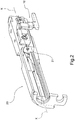
figure 2 shows a perspective view of a transversal cross-section of the slide containing a part of the detection system comprised in the firearm which the present invention relates to; -
figures 3 and 3a respectively show a side view and a plan view of the main body of the firearm according tofigure 1 containing a further part of the detection system comprised in the firearm which present invention relates to, according to a preferred embodiment; -
figures 4 and 4a respectively show two perspective views of the detection device, the idler device and the support device, comprised in the detection system according to a preferred embodiment comprising a detection device of a bullet in the barrel; -
figures 5 and 5a respectively show two side views of the detection device of the bullet in the barrel and of the idler device and the support device, according tofigures 4 and 4a respectively placed in an initial position and in a detection position; -
figure 6 shows a perspective view of the slide of the firearm shown in transparency, containing a part of the detection system comprised in the firearm according to the present invention, in which there is also a detection device of the release of the safety catch; -
figure 7 is a perspective view from below of the slide of the firearm, containing a part of the detection system comprised in the firearm according to the present invention, in which a device for detecting the release of the safety catch and a detection device of a bullet in the barrel are present; -
figure 8 shows a side perspective view of the detection device of the release of the safety catch according tofigures 7 and8 , respectively placed in an initial position and in a detection position; -
figure 9 shows a schematic representation of a portion of a firearm comprising a detection device comprising a detection device of locking of the firing pin and of the idler device and of the support device, according to a further embodiment; -
figure 9a shows a cross-section view offigure 9 , along the cross-section plane V-V infigure 9 ; - With reference to the appended drawings,
reference numeral 1 globally denotes a firearm in its entirety. - Preferably, said
firearm 1 comprises amain body 5, abarrel 2, which extends along a barrel axis X-X, and moving parts, such as aslide 20. Inside thebarrel 2, thefirearm 1 also has acartridge chamber 21, the chamber which the bullet is placed and subsequently fired. - In a preferred embodiment said
firearm 1 is a gun. - The
firearm 1 according to the present invention comprises adetection system 10 suitable for detecting a configuration change of the firearm compared to its initial configuration. In other words, thedetection system 10 is suitable to detect the presence or not of one or more changes in its configuration starting from an initial configuration in which it is not ready to fire, up to a configuration in which, instead, it is ready to fire. - Specifically, said
detection system 10 is suitable to detect the configuration change and to manage such information for example sending an alert to the user of thefirearm 1 or transmitting information remotely or storing the information. - In a preferred embodiment the
detection system 10 further comprises adetection device 100 suitable to detect such configuration change of thefirearm 1. In other words, thedetection device 100 is movable from one position to another depending on the configuration change of the firearm. In a preferred embodiment, therefore, thedetection device 100 is suitable to be placed in an initial position, corresponding to the initial configuration of thefirearm 1, and a detection position, which corresponds to the new configuration which thefirearm 1 is placed in. - According to a preferred embodiment, the
detection device 100 comprises a detection device of a bullet in thebarrel 110 suitable to detect the presence of a bullet in thecartridge chamber 21. The bullet with its presence in fact moves the detection device of the bullet in thebarrel 110 from an initial position to a detection position. In other words, the detection device of the bullet in thebarrel 110 comprises adetection portion 111 suitable to be positioned inside thecartridge chamber 21 and suitable to be moved by the bullet when it is positioned inside it. That is to say the detection device of the bullet in thebarrel 110 is suitable to be positioned in an initial position in which saiddetection portion 111 is placed inside thecartridge chamber 21, and to be moved into a detection position of the bullet in the barrel which comes into contact with thedetection portion 111 pushing it outside thecartridge chamber 21. - In a preferred embodiment the
detection portion 111 is of such dimensions as not to be particularly invasive inside thecartridge chamber 21. Preferably, thedetection portion 111 thus has the shape of a protrusion, preferably with a rounded tip, so as to make the contact with the bullet in the chamber more gradual. - Preferably, the
detection portion 111 protrudes into saidcartridge chamber 21 through a suitable opening made in the breech of thefirearm 1; said opening consequently has suitable dimensions to permit the passage of saiddetection portion 111 without affecting the behaviour, specifically the firing inside thecartridge chamber 21, of thefirearm 1. The presence of the bullet in the barrel thus entails that thedetection portion 111 is pushed into the opening on the breech. - Preferably, the
detection portion 111 protrudes inside the cartridge chamber by about 1 mm. - In a preferred embodiment, the
detection device 100 comprises a detection device of the release of thesafety catch 120, suitable to detect as a configuration change of thefirearm 1, the release of thesafety catch 28. The safety catch 28, in fact, moved by the user of thefirearm 1, moves in turn thedetection device 120 of the release of the safety catch from an initial position to a detection position. In other words, the detection device of the release of thesafety catch 120 includes anengagement portion 121 engaging thesafety lever 280 operable by the user. That is to say that the detection device of the release of thesafety catch 120 is suitable for being positioned in an initial position in which thesafety catch 28 is active, and suitable to be moved into a position of detection by the movement, translational and/or rotary, of thesafety catch 28, for example by pressure on thesafety lever 280. - According to a preferred embodiment, the detection device of the release of the
safety catch 120 is suitable to rotate following the rotation of thesafety catch 28, around its safety catch axis S-S. Preferably, the engagement between theengagement portion 121 and thesafety lever 280 is such as to permit a controlled rotation of the detection device. In other words, a rotation of 60 degrees of thesafety lever 280 corresponds to a rotation of 35 degrees of theengagement portion 121. In fact, preferably, the engagement between theengagement portion 121 andsafety lever 280 is achieved by a means of a cam or link coupling. For example, in a preferred embodiment, theengagement portion 121 and thesafety lever 280 are mutually engaged in such a way that an angle of rotation of thelever 280 is such that there is no interaction with theengagement portion 121, i.e. thelever 280 rotates alone, while at a second angle of rotation of thelever 280 this interacts with the engagement portion entailing its rotation in turn. - In a preferred embodiment, the
detection device 100 comprises a detection device of locking of thefiring pin 130, suitable to detect as a configuration change of thefirearm 1, the release of the locking element of thefiring pin 290 of thefirearm 1. In a firearm, for example of the automatic type, for firing to take place, once the trigger is pressed, a kinematic chain of movements inside begins, among which the movement of thefiring pin lock 290, which then allows thefiring pin 29 to move freely to perform the explosion and fire. Preferably, in the initial firearm configuration, thus in the initial position of the detection device of locking of thefiring pin 130, thefiring pin 29 is locked by the firingpin locking element 290; when the trigger is pressed to perform firing, thefirearm 1 changes configuration: thanks to a series of levers the firingpin locking element 290 is moved, for example vertically, upwards, to release thefiring pin 29. - Preferably, the detection device of locking of the
firing pin 130 comprises, in fact, a coupling portion operationally locked to thefiring pin element 290, and thus for example translated following the movement thereof. - In a preferred embodiment the
detection system 10 further comprises anidler device 200 engaged with thedetection device 100. - Preferably said
idler device 200 is driven, in turn, like thedetection device 100, into an initial position and a detection position. In particular, said movement of theidler device 200 is a direct function of the movement of thedetection device 100. In a preferred embodiment, for example the initial position of thedetection device 100, for example of thedetection portion 111, corresponds to an initial position of theidler device 200, and a detection position of thedetection device 100, and in particular of thedetection portion 111, corresponds to a detection position of theidler device 200. - In a preferred embodiment the
idler device 200 comprises at least oneprimary sensor element 250, suitable to indicate the position assumed by saididler device 200. For example, theprimary sensor element 250 is suitable to indicate the position of theidler device 200 as a function of thedetection device 100 and thus of the configuration change of thefirearm 1. - In a preferred embodiment, a translatory movement of the detection device corresponds to a translatory movement of the idler device. In further embodiments, a rotary movement of the detection device corresponds to a rotary movement of the idler device. However mixed embodiments are provided for in which the interaction, translatory or rotary, between the detection device and the idler device is variable, depending, for example, on their position inside the firearm, namely the first performs a movement in translation while the second performs it in rotation. Or again, embodiments are also provided for in which the movement itself of the devices is mixed, for example, being moved into rototranslation.
- According to further preferred embodiments, instead, the
detection device 100 and theidler device 200 are integrally connected to one another, for example being part of the same component, and thus perform a movement in unison. In other words, in some embodiments, solutions are also provided for in which theidler device 200 is integral with thedetection device 100, for example in the case with theengagement portion 120 shown in the appended drawings, and thus theidler device 200 replicates the movement of thedetection device 100. - In further embodiments, the
idler device 200 is suitable to spatially multiply the movement of thedetection device 100. In other words, theidler device 200 is suitable to perform a broader movement compared to the movement of thedetection device 100. Instead in other embodiments, theidler device 200 is suitable to spatially reduce the movement of thedetection device 100. In other words, theidler device 200 is suitable to perform a narrower movement compared to the movement of thedetection device 100. - For example, in one embodiment, the
detection device 100 is rotatable, performs a rotary movement, while, instead, theidler device 200 is translating, therefore when it is moved by thedetection device 100 it performs a translatory, linear movement. - In a preferred embodiment the
idler device 200 comprises acam element 280, engaged with thedetection device 100 in such a way as to be suitable to convert the rotary movement of the latter into a translatory movement of theidler device 200. - In a preferred embodiment the
detection system 10 further comprises asupport device 400 suitable to support thedetection device 100 and theidler device 200. - Preferably, the
detection device 100 is hinged to thesupport device 400, for example on a pin provided. - Preferably moreover the
idler device 200 is suitable to translate along thesupport device 400. - Again, in a further preferred embodiment, the
support device 400 comprises anelastic element 401 engaging thedetection device 100 to keep it in an initial position. - For example, applied to the detection device of the bullet in the
barrel 110, theelastic element 401 in keeping this initial position thus keeps thedetection portion 111 inside thecartridge chamber 21, protruding from the breech. This way when the bullet is placed in thecartridge chamber 21 it overcomes the resistance of theelastic element 401 pushing thedetection portion 111 and thus the detection device of the bullet in thebarrel 110 into the detection position. Since theidler device 200 is engaged with the detection device of the bullet in thebarrel 110, theelastic element 401 keeps it, in turn, in an initial or detection position depending on the embodiment. - In a preferred embodiment the
support device 400 is housed on theslide 20 of thefirearm 1, and is therefore suitable to engage thedetection device 100 and theidler device 200 with saidslide 20. - In a preferred embodiment the
detection system 10 comprises areceiver device 300 suitable to receive the information of the configuration change of thefirearm 1 upon the signalling of thedetection device 100, that is, of theidler device 200, thus of theprimary sensor element 250. - Preferably, said
receiver device 300 after receiving the information of the configuration change or not is suitable to manage such information, for example alerting the user of thefirearm 1 by suitable signalling means and/or by storing the information or transmitting it, sending it remotely; preferably, said signalling means of the bullet in the barrel are suitable to produce an acoustic or visual type signal indicating the information desired. In a preferred embodiment, said signalling means are on the firearm itself, or in other embodiments are located remotely. Preferably said means of signalling the presence of the bullet in the barrel may be remote from the firearm and receive the information after sending thereof. - Preferably, the
receiver device 300, in order to receive the information of the presence of the bullet in the barrel or not comprises at least onesecondary sensor element 350. - Preferably, the
primary sensor element 250 andsecondary sensor element 350 are magnetically sensitive to one another. - Therefore, depending on the mutual position thereof, the
secondary sensor element 350 is suitable to receive, since magnetically solicited by theprimary sensor element 250, information of the position of theidler device 200. - Preferably, the
primary sensor element 250 is a ferromagnetic element while thesecondary sensor element 350 is sensitive to the magnetic field, as is for example an electrical coil, or again a ferromagnetic element. - In a further embodiment, the
secondary sensor element 350 is of the mechanical type: in other words thesecondary sensor element 350 is a mechanical switch. Thesecondary sensor element 350, in fact, contains a lamella which when magnetically solicited is suitable to move and thus close an electrical circuit, thereby transmitting the information. - In a preferred embodiment the
idler device 200 comprises two of theprimary sensor elements 250 and/or thereceiver device 300 comprises twosecondary sensor elements 350, wherein the twoprimary sensor elements 250 and/or twosecondary sensor elements 350 are positioned staggered with each other; or in further embodiments said pairs of sensors are distanced from each other by a predefined distance, in the direction of movement of theidler device 200. - Preferably, this way, the
receiver device 300 by means of thesecondary sensor element 350, is suitable to be influenced by the presence of one or moresecondary sensor elements 250 depending on the position of the latter. - Or in other embodiment variants, the
receiver device 300 comprises twosecondary sensor elements 350, influenced, for example, simultaneously, by the presence of at least oneprimary sensor element 250. - For example in a configuration in which the
detection device 100 is in the initial position, aprimary sensor element 250 is positioned between twosecondary sensor elements 350 and/or asecondary sensor element 350 is positioned between twoprimary sensor elements 250. Subsequently, when thedetection device 100 is moved to the rearward position theprimary sensor element 250, first positioned between twosecondary sensor elements 350, moves so as to influence only one of saidsecondary sensor elements 350; and similarly, in the other embodiment variant, thesecondary sensor element 350, first positioned between twoprimary sensor elements 250, is influenced by only one of saidprimary sensor elements 250 and no longer by both. - In fact, depending on the embodiment variants, and the number of sensor elements comprised in the
detection system 10, thereceiver device 300 is calibrated according to the type of the magnetic fields to which the respective secondary sensor element orelements 350 is or are magnetically sensitive. - In a preferred embodiment, the
idler device 200 comprises asensor support portion 210, on which theprimary sensor element 250 is housed which extends along a secondary axis Y-Y parallel to the barrel axis X-X. Preferably, theidler device 200 is suitable to translate along said secondary axis Y-Y. - Preferably, the at least one
primary sensor element 250 and/or the at least onesecondary sensor element 350 is positioned along said secondary axis Y-Y. - In particular, according to a preferred embodiment, the
receiver device 300 is placed on the main body of thefirearm 5 and thedetection device 100 and theidler device 200 are positioned on theslide 20 of thefirearm 1. - Specifically, according to said embodiment the
primary sensor element 250 is housed on theslide 20 facing themain body 5, and thesecondary sensor element 350 is housed on themain body 5 facing theslide 20. This way, the two sensor elements are suitable to influence one another magnetically. - Preferably, therefore the
sensor support element 210 is placed on theslide 20 facing themain body 5. In a preferred embodiment, therefore, saidsensor 210 support element extends along theslide 20. - Furthermore, the
detection system 10 comprises a slide position device comprising a primaryslide sensor element 650 housed in a fixed manner on theslide 20, and thus translating therewith along the barrel axis X-X. Thereceiver device 300 comprises, on themain body 5, a secondaryslide sensor element 356. The two elements are magnetically sensitive to one another, according to the embodiments already described above. This way the movement of theslide 20, thereceiver device 300, and in particular its secondaryslide sensor element 356, is magnetically solicited by the variation of the magnetic field due to the primaryslide sensor element 650 moved. - According to the above description, and according to the type of sensor elements comprised in the firearm, it is to be noted that in some embodiments, both in the initial configuration and in the detection configuration said sensor elements are mutually influenced by one another; however, following the configuration change of the firearm a change of said mutual influence takes place, for example as a result of the change in intensity of the magnetic field, this change is thus detected by the respective detection device as the configuration change.
- Innovatively the firearm of the present invention resolves the typical drawbacks of the prior art, comprising a non-invasive detection system, specifically suitable to not influence the design, production, or reciprocal movement between the slide and the main body.
- Advantageously, in fact, the detection system comprises sensor elements suitable to communicate with each other, sending each other information without revolutionising the structure of the firearm, inasmuch as magnetically sensitive to each other.
- In addition, advantageously, a part of the detection device is positioned on the slide, while the other part is positioned in the main body of the firearm; this way the components mounted on the slide are of small dimensions and do not affect its movement, while the components of greater dimensions can be situated on the main body of the firearm. As mentioned, however, the various components housed on different bodies communicate with each other in a wireless mode, without a material type connection, using the magnetic sensitivity of the various sensors.
- According to a further advantageous aspect, the firearm of the present invention has the same characteristics of dismantling, with the same phases, present on a similar firearm without the detection system; this is made possible thanks to the fact that the detection system, between the mobile masses and fixed masses, does not provide for any connection of a material type.
- According to another further advantageous aspect, the primary sensor element and secondary sensor element respectively face one another on the slide and the main body so as to reciprocally influence each other magnetically.
- Advantageously, the management of the magnetic interaction mode between the components is of simple construction, for example comprising at least one of the two sensor elements as a ferromagnetic element therefore suitable to have a specific magnetic field and the other as a magnetically sensitive element, being in turn a magnet, or an electrical circuit being influenced by said magnetic field, or being any other type of magnetically sensitive elements or being a "hybrid system" comprising more than one of said characteristics.
- Advantageously, the detection system comprises a variable number of sensor elements according to the various embodiments, this way such embodiments are particularly advantageous in that they use the destructive and/or constructive interference of the magnetic fields of the elements including the sensors.
- According to a further advantageous aspect, the idler device is suitable to transform and multiply or reduce the movement of the detection device, thus minimising the invasiveness of the detection portion in the cartridge chamber.
- According to yet a further advantageous aspect, the non-invasiveness of the detection system of the present invention makes it applicable to firearms of small dimensions, such as guns.
- Advantageously, the detection system is suitable, depending on the type of the specific detection devices present on the firearm, to detect a multiplicity of configuration changes of the firearm, and then to store or transmit only some of these or a combination thereof.
- Further embodiments of the firearm of the present invention provide for a variable number or mutual positioning of the various sensor elements, both primary and secondary, so as to detect more precisely the presence of the bullet in the barrel and/or of the obturator.
- Embodiment variants provided for further comprise solutions in which the firearm, by suitable means, is prevented or not from firing depending on the findings of the detection system.
- Moreover, in further embodiment variants, the magnetic interaction between the various sensors induces a movement of some in relation to others; for example, in one embodiment the magnetic interaction may induce the primary or the secondary sensor element to move under the effect of the aforesaid magnetic field induced.
- In further embodiment variants the primary and/or secondary sensor elements are magnetically sensitive exploiting the Hall effect, thus presenting electrical circuits more or less sensitive to magnetic fields, or more or less reproducible magnetic fields.
- It is clear that a person skilled in the art may make modifications to the firearm described above so as to satisfy contingent requirements while remaining within the scope of the following claims.
Claims (17)
- Firearm (1) comprising a main body (5), a barrel (2), a slide (20), and a detection system (10) suitable to detect a configuration change of the firearm from an initial configuration, wherein said detection system (10) comprises:- a detection device (100), housed on board said slide (20), suitable to be positioned in an initial position corresponding to the initial configuration of the firearm, and suitable to be moved into a detection position in which it detects the configuration change of the firearm, such as the release of a safety catch;- an idler device (200), housed on board said slide (20), engaged with the detection device (100) and moved, in turn, into an initial position and a detection position according to the movement of the detection device (100), wherein the idler device (200) comprises at least one primary sensor element (250);- a receiver device (300), housed on board said main body (5), suitable to receive the information of the configuration change of the firearm depending on the position of the primary sensor element (250), comprising at least one secondary sensor element ( 350);wherein the primary sensor element (250) and secondary sensor element (350) are magnetically sensitive to one another.
- Firearm (1) according to the previous claim, wherein the detection device (100) is rotatable and the idler device (200) is translatable or wherein the detection device (100) is rotatable and the idler device (200) is in turn rotatable.
- Firearm (1) according to any of the previous claims, wherein the detection device (100) comprises a detection device of a bullet in the barrel (110) suitable to detect the presence of a bullet in the cartridge chamber (21) of the firearm, comprising a detection portion (111) which, in the initial configuration of the firearm, namely the initial position of the detection device (100), is placed inside said cartridge chamber (21), and is movable into a detection position of the bullet in the barrel, corresponding to the detection position.
- Firearm (1) according to any of the previous claims, wherein the detection device (100) comprises a detection device of the release of the safety catch (120) suitable to detect the release of a safety catch (28) of the firearm, comprising an engagement portion (121) engaging the safety lever (280) controllable by the user, so that in the initial configuration of the firearm, namely the initial position of the detection device (100), the safety catch (28) is inserted, and is movable into a translated and/or rotated position by the release of the safety catch (28), corresponding to the detection position.
- Firearm (1) according to any of the previous claims, wherein the detection device (100) comprises a detection device of locking of a firing pin (130), suitable to detect the release of the locking element (290) of the firing pin (29) of the firearm, comprising a coupling portion operationally locked to the locking element of the firing pin, so that in the initial configuration of the firearm, namely the initial position of the detection device, the firing pin (29) is locked by the locking element, and is movable in translation into a release position, by the release of the locking element of the firing pin (290) controlled by an action of the user on the trigger, corresponding to the detection position.
- Firearm (1) according to any of the previous claims, wherein the idler device (200) comprises a sensor support portion (210) suitable to house at least the primary sensor element (250), preferably the support portion extends along a secondary axis (Y-Y) parallel to a barrel axis (X-X) along which the barrel (2) extends.
- Firearm (1) according to claim 6, wherein the primary sensor element (250) and/or the secondary sensor element (350) is positioned along said secondary axis (Y-Y).
- Firearm (1) according to any of the previous claims, wherein the detection system (10) further comprises a slide position device (600) comprising a primary slide sensor element (650) housed in a fixed manner on the slide (20) and wherein the receiver device (300) comprises a secondary slide sensor element (356), wherein the primary slide sensor element (650) and secondary slide sensor element (356) are magnetically sensitive to one another.
- Firearm (1) according to any of the previous claims, wherein the idler device (200) comprises two primary sensor elements (250) and/or the receiver device (300) comprises two secondary sensor elements (350), wherein the two primary sensor elements (250) and/or the two secondary sensor elements (350) are positioned staggered from each other in the direction of movement of the idler device (200).
- Firearm (1) according to claim 9, wherein, in a configuration in which the detection device is in the initial position, a primary sensor element (250) is positioned between the two secondary sensor elements (350) and/or a secondary sensor element (350) is positioned between the two primary sensor elements (250).
- Firearm (1) according to any of the previous claims, wherein the primary sensor element (250) is housed on the slide (20) facing the main body (5), and the secondary sensor element (350) is housed on the main body (5) facing the slide (20).
- Firearm (1) according to any of the previous claims, wherein the detection system (10) comprises a support device (400) suitable for supporting the detection device (100) and the idler device (200) engaging them with the slide (20).
- Firearm (1) according to claim 12, wherein the detection system (100) is hinged to the support device (400) .
- Firearm (1) according to claim 12 or 13, wherein the idler device (200) is suitable to translate or rotate along the support device (400).
- Firearm (1) according to claims 12 to 14, wherein the support device (400) comprises an elastic element (401) engaging the detection device (100) to keep it in the initial position.
- Firearm (1) according to any of the previous claims, wherein the receiver device (300) comprises signalling means of the bullet in the barrel suitable to signal to the user the presence or absence of the bullet in the barrel.
- Firearm (1) according to any of the previous claims, wherein said firearm is a gun.
Applications Claiming Priority (1)
| Application Number | Priority Date | Filing Date | Title |
|---|---|---|---|
| PCT/IT2014/000255 WO2016046850A1 (en) | 2014-09-26 | 2014-09-26 | Firearm with change configuration detection system |
Publications (2)
| Publication Number | Publication Date |
|---|---|
| EP3198216A1 EP3198216A1 (en) | 2017-08-02 |
| EP3198216B1 true EP3198216B1 (en) | 2018-08-01 |
Family
ID=52278691
Family Applications (1)
| Application Number | Title | Priority Date | Filing Date |
|---|---|---|---|
| EP14821863.9A Active EP3198216B1 (en) | 2014-09-26 | 2014-09-26 | Firearm with change configuration detection system |
Country Status (3)
| Country | Link |
|---|---|
| US (1) | US10001329B2 (en) |
| EP (1) | EP3198216B1 (en) |
| WO (1) | WO2016046850A1 (en) |
Families Citing this family (12)
| Publication number | Priority date | Publication date | Assignee | Title |
|---|---|---|---|---|
| US20190222771A1 (en) | 2016-10-14 | 2019-07-18 | Laser Aiming Systems Corporation | Gun-mounted recording device |
| US10962314B2 (en) | 2017-04-12 | 2021-03-30 | Laser Aiming Systems Corporation | Firearm including electronic components to enhance user experience |
| USD883413S1 (en) * | 2017-08-16 | 2020-05-05 | Wilson's Gun Shop, Inc | Handgun slide |
| US10760861B2 (en) * | 2018-01-22 | 2020-09-01 | Springfield, Inc. | Firearm slide with sloped bottom surface |
| EP3762674A4 (en) | 2018-03-08 | 2021-11-24 | Maztech Industries, LLC | SYSTEM FOR DETECTION OF THE AVAILABILITY OF ARMS AMMUNITION |
| US11971238B2 (en) | 2018-10-22 | 2024-04-30 | Magpul Industries Corp. | Determination of round count by hall switch encoding |
| US11719497B2 (en) | 2018-10-22 | 2023-08-08 | Magpul Industries Corp. | Determination of round count by hall switch encoding |
| CN110095016B (en) * | 2019-04-17 | 2019-12-31 | 沈阳顺义科技有限公司 | A tank weapon system state detection device and detection method |
| US12130121B1 (en) | 2020-07-21 | 2024-10-29 | Laser Aiming Systems Corporation | Data redundancy and hardware tracking system for gun-mounted recording device |
| US12173992B1 (en) | 2020-07-21 | 2024-12-24 | Laser Aiming Systems Corporation | Gun mounted recording device with quick release battery |
| WO2023086840A1 (en) | 2021-11-12 | 2023-05-19 | Maztech Industries, LLC | Firearm ammunition availability detection system |
| US20250164204A1 (en) * | 2023-11-21 | 2025-05-22 | Arthur J. Elftmann, JR. | Skipless trigger systems and methods |
Family Cites Families (6)
| Publication number | Priority date | Publication date | Assignee | Title |
|---|---|---|---|---|
| DE4413685A1 (en) * | 1993-04-23 | 1994-10-27 | Horst Blaser | Safety device for hunting and sporting weapons |
| US7661217B2 (en) * | 2006-11-15 | 2010-02-16 | Dov Pikielny | Shot counter |
| US8245426B2 (en) * | 2007-02-07 | 2012-08-21 | Dov Pikielny | Firearm with loaded / un-loaded identification system |
| DE102007063679A1 (en) * | 2007-12-24 | 2009-09-10 | Carl Walther Gmbh | Electrical signal producing device for use in fire arm during gun battle, has signal transmitting device generating signal data representing shot-specific data, during firing, where signal data contains certainty, date and time of firing |
| DE102011106200B4 (en) * | 2011-06-07 | 2016-03-17 | Rheinmetall Air Defence Ag | Firing pin safety |
| FI126883B (en) * | 2013-09-24 | 2017-07-14 | Miklatech Oy | Security arrangements for firearms |
-
2014
- 2014-09-26 EP EP14821863.9A patent/EP3198216B1/en active Active
- 2014-09-26 US US15/501,724 patent/US10001329B2/en active Active
- 2014-09-26 WO PCT/IT2014/000255 patent/WO2016046850A1/en not_active Ceased
Also Published As
| Publication number | Publication date |
|---|---|
| US20170227310A1 (en) | 2017-08-10 |
| US10001329B2 (en) | 2018-06-19 |
| WO2016046850A1 (en) | 2016-03-31 |
| EP3198216A1 (en) | 2017-08-02 |
Similar Documents
| Publication | Publication Date | Title |
|---|---|---|
| US10001329B2 (en) | Firearm with change configuration detection system | |
| EP3295110B1 (en) | Firearm comprising a magazine detection group | |
| US11971238B2 (en) | Determination of round count by hall switch encoding | |
| US8850734B2 (en) | Trigger assembly and system including a blocking mechanism | |
| US11015890B2 (en) | Determination of round count by hall switch encoding | |
| US10900732B2 (en) | Electromagnetic firing system for firearm with firing event tracking | |
| US12535283B2 (en) | Determination of round count by hall switch encoding | |
| US12385708B2 (en) | Safety for firearm electromagnetic firing system | |
| US11300378B2 (en) | Electromagnetic firing system for firearm with interruptable trigger control | |
| US12078434B2 (en) | Device and method for securing a gun | |
| WO2015044903A1 (en) | Firearm with bullet in the barrel detection system | |
| EP2613117A2 (en) | Trigger assembly and system including a blocking mechanism | |
| US20250297820A1 (en) | Firearm magazine with round counter | |
| EP3270089B1 (en) | Cartridge-in-chamber detection system for firearms | |
| TW202136704A (en) | Determination of round count by hall switch encoding | |
| EP4500102A1 (en) | Safety for firearm electromagnetic firing system | |
| EP4168728A1 (en) | Electromagnetic firing system for firearm with interruptable trigger control |
Legal Events
| Date | Code | Title | Description |
|---|---|---|---|
| PUAI | Public reference made under article 153(3) epc to a published international application that has entered the european phase |
Free format text: ORIGINAL CODE: 0009012 |
|
| 17P | Request for examination filed |
Effective date: 20170112 |
|
| AK | Designated contracting states |
Kind code of ref document: A1 Designated state(s): AL AT BE BG CH CY CZ DE DK EE ES FI FR GB GR HR HU IE IS IT LI LT LU LV MC MK MT NL NO PL PT RO RS SE SI SK SM TR |
|
| AX | Request for extension of the european patent |
Extension state: BA ME |
|
| DAX | Request for extension of the european patent (deleted) | ||
| GRAP | Despatch of communication of intention to grant a patent |
Free format text: ORIGINAL CODE: EPIDOSNIGR1 |
|
| INTG | Intention to grant announced |
Effective date: 20180222 |
|
| RIN1 | Information on inventor provided before grant (corrected) |
Inventor name: SARDINI, EMILIO Inventor name: GORZA, ROBERTO Inventor name: RIGHI, EUGENIO |
|
| GRAS | Grant fee paid |
Free format text: ORIGINAL CODE: EPIDOSNIGR3 |
|
| GRAA | (expected) grant |
Free format text: ORIGINAL CODE: 0009210 |
|
| AK | Designated contracting states |
Kind code of ref document: B1 Designated state(s): AL AT BE BG CH CY CZ DE DK EE ES FI FR GB GR HR HU IE IS IT LI LT LU LV MC MK MT NL NO PL PT RO RS SE SI SK SM TR |
|
| REG | Reference to a national code |
Ref country code: GB Ref legal event code: FG4D |
|
| REG | Reference to a national code |
Ref country code: CH Ref legal event code: EP Ref country code: AT Ref legal event code: REF Ref document number: 1024809 Country of ref document: AT Kind code of ref document: T Effective date: 20180815 |
|
| REG | Reference to a national code |
Ref country code: IE Ref legal event code: FG4D |
|
| REG | Reference to a national code |
Ref country code: DE Ref legal event code: R096 Ref document number: 602014029679 Country of ref document: DE |
|
| REG | Reference to a national code |
Ref country code: NL Ref legal event code: MP Effective date: 20180801 |
|
| REG | Reference to a national code |
Ref country code: LT Ref legal event code: MG4D |
|
| REG | Reference to a national code |
Ref country code: AT Ref legal event code: MK05 Ref document number: 1024809 Country of ref document: AT Kind code of ref document: T Effective date: 20180801 |
|
| PG25 | Lapsed in a contracting state [announced via postgrant information from national office to epo] |
Ref country code: GR Free format text: LAPSE BECAUSE OF FAILURE TO SUBMIT A TRANSLATION OF THE DESCRIPTION OR TO PAY THE FEE WITHIN THE PRESCRIBED TIME-LIMIT Effective date: 20181102 Ref country code: SE Free format text: LAPSE BECAUSE OF FAILURE TO SUBMIT A TRANSLATION OF THE DESCRIPTION OR TO PAY THE FEE WITHIN THE PRESCRIBED TIME-LIMIT Effective date: 20180801 Ref country code: PL Free format text: LAPSE BECAUSE OF FAILURE TO SUBMIT A TRANSLATION OF THE DESCRIPTION OR TO PAY THE FEE WITHIN THE PRESCRIBED TIME-LIMIT Effective date: 20180801 Ref country code: LT Free format text: LAPSE BECAUSE OF FAILURE TO SUBMIT A TRANSLATION OF THE DESCRIPTION OR TO PAY THE FEE WITHIN THE PRESCRIBED TIME-LIMIT Effective date: 20180801 Ref country code: RS Free format text: LAPSE BECAUSE OF FAILURE TO SUBMIT A TRANSLATION OF THE DESCRIPTION OR TO PAY THE FEE WITHIN THE PRESCRIBED TIME-LIMIT Effective date: 20180801 Ref country code: FI Free format text: LAPSE BECAUSE OF FAILURE TO SUBMIT A TRANSLATION OF THE DESCRIPTION OR TO PAY THE FEE WITHIN THE PRESCRIBED TIME-LIMIT Effective date: 20180801 Ref country code: NL Free format text: LAPSE BECAUSE OF FAILURE TO SUBMIT A TRANSLATION OF THE DESCRIPTION OR TO PAY THE FEE WITHIN THE PRESCRIBED TIME-LIMIT Effective date: 20180801 Ref country code: AT Free format text: LAPSE BECAUSE OF FAILURE TO SUBMIT A TRANSLATION OF THE DESCRIPTION OR TO PAY THE FEE WITHIN THE PRESCRIBED TIME-LIMIT Effective date: 20180801 Ref country code: BG Free format text: LAPSE BECAUSE OF FAILURE TO SUBMIT A TRANSLATION OF THE DESCRIPTION OR TO PAY THE FEE WITHIN THE PRESCRIBED TIME-LIMIT Effective date: 20181101 Ref country code: IS Free format text: LAPSE BECAUSE OF FAILURE TO SUBMIT A TRANSLATION OF THE DESCRIPTION OR TO PAY THE FEE WITHIN THE PRESCRIBED TIME-LIMIT Effective date: 20181201 Ref country code: NO Free format text: LAPSE BECAUSE OF FAILURE TO SUBMIT A TRANSLATION OF THE DESCRIPTION OR TO PAY THE FEE WITHIN THE PRESCRIBED TIME-LIMIT Effective date: 20181101 |
|
| PG25 | Lapsed in a contracting state [announced via postgrant information from national office to epo] |
Ref country code: AL Free format text: LAPSE BECAUSE OF FAILURE TO SUBMIT A TRANSLATION OF THE DESCRIPTION OR TO PAY THE FEE WITHIN THE PRESCRIBED TIME-LIMIT Effective date: 20180801 Ref country code: LV Free format text: LAPSE BECAUSE OF FAILURE TO SUBMIT A TRANSLATION OF THE DESCRIPTION OR TO PAY THE FEE WITHIN THE PRESCRIBED TIME-LIMIT Effective date: 20180801 Ref country code: HR Free format text: LAPSE BECAUSE OF FAILURE TO SUBMIT A TRANSLATION OF THE DESCRIPTION OR TO PAY THE FEE WITHIN THE PRESCRIBED TIME-LIMIT Effective date: 20180801 |
|
| PG25 | Lapsed in a contracting state [announced via postgrant information from national office to epo] |
Ref country code: EE Free format text: LAPSE BECAUSE OF FAILURE TO SUBMIT A TRANSLATION OF THE DESCRIPTION OR TO PAY THE FEE WITHIN THE PRESCRIBED TIME-LIMIT Effective date: 20180801 Ref country code: RO Free format text: LAPSE BECAUSE OF FAILURE TO SUBMIT A TRANSLATION OF THE DESCRIPTION OR TO PAY THE FEE WITHIN THE PRESCRIBED TIME-LIMIT Effective date: 20180801 Ref country code: CZ Free format text: LAPSE BECAUSE OF FAILURE TO SUBMIT A TRANSLATION OF THE DESCRIPTION OR TO PAY THE FEE WITHIN THE PRESCRIBED TIME-LIMIT Effective date: 20180801 Ref country code: ES Free format text: LAPSE BECAUSE OF FAILURE TO SUBMIT A TRANSLATION OF THE DESCRIPTION OR TO PAY THE FEE WITHIN THE PRESCRIBED TIME-LIMIT Effective date: 20180801 Ref country code: MC Free format text: LAPSE BECAUSE OF FAILURE TO SUBMIT A TRANSLATION OF THE DESCRIPTION OR TO PAY THE FEE WITHIN THE PRESCRIBED TIME-LIMIT Effective date: 20180801 |
|
| REG | Reference to a national code |
Ref country code: CH Ref legal event code: PL |
|
| REG | Reference to a national code |
Ref country code: DE Ref legal event code: R097 Ref document number: 602014029679 Country of ref document: DE |
|
| PG25 | Lapsed in a contracting state [announced via postgrant information from national office to epo] |
Ref country code: SK Free format text: LAPSE BECAUSE OF FAILURE TO SUBMIT A TRANSLATION OF THE DESCRIPTION OR TO PAY THE FEE WITHIN THE PRESCRIBED TIME-LIMIT Effective date: 20180801 Ref country code: DK Free format text: LAPSE BECAUSE OF FAILURE TO SUBMIT A TRANSLATION OF THE DESCRIPTION OR TO PAY THE FEE WITHIN THE PRESCRIBED TIME-LIMIT Effective date: 20180801 Ref country code: SM Free format text: LAPSE BECAUSE OF FAILURE TO SUBMIT A TRANSLATION OF THE DESCRIPTION OR TO PAY THE FEE WITHIN THE PRESCRIBED TIME-LIMIT Effective date: 20180801 |
|
| PLBE | No opposition filed within time limit |
Free format text: ORIGINAL CODE: 0009261 |
|
| STAA | Information on the status of an ep patent application or granted ep patent |
Free format text: STATUS: NO OPPOSITION FILED WITHIN TIME LIMIT |
|
| REG | Reference to a national code |
Ref country code: IE Ref legal event code: MM4A |
|
| PG25 | Lapsed in a contracting state [announced via postgrant information from national office to epo] |
Ref country code: LU Free format text: LAPSE BECAUSE OF NON-PAYMENT OF DUE FEES Effective date: 20180926 |
|
| 26N | No opposition filed |
Effective date: 20190503 |
|
| GBPC | Gb: european patent ceased through non-payment of renewal fee |
Effective date: 20181101 |
|
| PG25 | Lapsed in a contracting state [announced via postgrant information from national office to epo] |
Ref country code: IE Free format text: LAPSE BECAUSE OF NON-PAYMENT OF DUE FEES Effective date: 20180926 |
|
| PG25 | Lapsed in a contracting state [announced via postgrant information from national office to epo] |
Ref country code: LI Free format text: LAPSE BECAUSE OF NON-PAYMENT OF DUE FEES Effective date: 20180930 Ref country code: FR Free format text: LAPSE BECAUSE OF NON-PAYMENT OF DUE FEES Effective date: 20181001 Ref country code: SI Free format text: LAPSE BECAUSE OF FAILURE TO SUBMIT A TRANSLATION OF THE DESCRIPTION OR TO PAY THE FEE WITHIN THE PRESCRIBED TIME-LIMIT Effective date: 20180801 Ref country code: CH Free format text: LAPSE BECAUSE OF NON-PAYMENT OF DUE FEES Effective date: 20180930 |
|
| PG25 | Lapsed in a contracting state [announced via postgrant information from national office to epo] |
Ref country code: GB Free format text: LAPSE BECAUSE OF NON-PAYMENT OF DUE FEES Effective date: 20181101 |
|
| PG25 | Lapsed in a contracting state [announced via postgrant information from national office to epo] |
Ref country code: MT Free format text: LAPSE BECAUSE OF NON-PAYMENT OF DUE FEES Effective date: 20180926 |
|
| PG25 | Lapsed in a contracting state [announced via postgrant information from national office to epo] |
Ref country code: TR Free format text: LAPSE BECAUSE OF FAILURE TO SUBMIT A TRANSLATION OF THE DESCRIPTION OR TO PAY THE FEE WITHIN THE PRESCRIBED TIME-LIMIT Effective date: 20180801 |
|
| PG25 | Lapsed in a contracting state [announced via postgrant information from national office to epo] |
Ref country code: PT Free format text: LAPSE BECAUSE OF FAILURE TO SUBMIT A TRANSLATION OF THE DESCRIPTION OR TO PAY THE FEE WITHIN THE PRESCRIBED TIME-LIMIT Effective date: 20180801 |
|
| PG25 | Lapsed in a contracting state [announced via postgrant information from national office to epo] |
Ref country code: CY Free format text: LAPSE BECAUSE OF FAILURE TO SUBMIT A TRANSLATION OF THE DESCRIPTION OR TO PAY THE FEE WITHIN THE PRESCRIBED TIME-LIMIT Effective date: 20180801 Ref country code: HU Free format text: LAPSE BECAUSE OF FAILURE TO SUBMIT A TRANSLATION OF THE DESCRIPTION OR TO PAY THE FEE WITHIN THE PRESCRIBED TIME-LIMIT; INVALID AB INITIO Effective date: 20140926 Ref country code: MK Free format text: LAPSE BECAUSE OF NON-PAYMENT OF DUE FEES Effective date: 20180801 |
|
| P01 | Opt-out of the competence of the unified patent court (upc) registered |
Effective date: 20230522 |
|
| PGFP | Annual fee paid to national office [announced via postgrant information from national office to epo] |
Ref country code: DE Payment date: 20250923 Year of fee payment: 12 |
|
| PGFP | Annual fee paid to national office [announced via postgrant information from national office to epo] |
Ref country code: IT Payment date: 20250704 Year of fee payment: 12 |
|
| PGFP | Annual fee paid to national office [announced via postgrant information from national office to epo] |
Ref country code: BE Payment date: 20250918 Year of fee payment: 12 |