EP3197814B1 - Methods and apparatus for constructing glass furnace structures - Google Patents
Methods and apparatus for constructing glass furnace structures Download PDFInfo
- Publication number
- EP3197814B1 EP3197814B1 EP15771467.6A EP15771467A EP3197814B1 EP 3197814 B1 EP3197814 B1 EP 3197814B1 EP 15771467 A EP15771467 A EP 15771467A EP 3197814 B1 EP3197814 B1 EP 3197814B1
- Authority
- EP
- European Patent Office
- Prior art keywords
- beams
- pairs
- cross
- regenerator structure
- support
- Prior art date
- Legal status (The legal status is an assumption and is not a legal conclusion. Google has not performed a legal analysis and makes no representation as to the accuracy of the status listed.)
- Active
Links
Images




Classifications
-
- B—PERFORMING OPERATIONS; TRANSPORTING
- B66—HOISTING; LIFTING; HAULING
- B66C—CRANES; LOAD-ENGAGING ELEMENTS OR DEVICES FOR CRANES, CAPSTANS, WINCHES, OR TACKLES
- B66C17/00—Overhead travelling cranes comprising one or more substantially horizontal girders the ends of which are directly supported by wheels or rollers running on tracks carried by spaced supports
- B66C17/06—Overhead travelling cranes comprising one or more substantially horizontal girders the ends of which are directly supported by wheels or rollers running on tracks carried by spaced supports specially adapted for particular purposes, e.g. in foundries, forges; combined with auxiliary apparatus serving particular purposes
-
- B—PERFORMING OPERATIONS; TRANSPORTING
- B66—HOISTING; LIFTING; HAULING
- B66B—ELEVATORS; ESCALATORS OR MOVING WALKWAYS
- B66B9/00—Kinds or types of lifts in, or associated with, buildings or other structures
- B66B9/16—Mobile or transportable lifts specially adapted to be shifted from one part of a building or other structure to another part or to another building or structure
-
- B—PERFORMING OPERATIONS; TRANSPORTING
- B66—HOISTING; LIFTING; HAULING
- B66C—CRANES; LOAD-ENGAGING ELEMENTS OR DEVICES FOR CRANES, CAPSTANS, WINCHES, OR TACKLES
- B66C23/00—Cranes comprising essentially a beam, boom, or triangular structure acting as a cantilever and mounted for translatory of swinging movements in vertical or horizontal planes or a combination of such movements, e.g. jib-cranes, derricks, tower cranes
- B66C23/18—Cranes comprising essentially a beam, boom, or triangular structure acting as a cantilever and mounted for translatory of swinging movements in vertical or horizontal planes or a combination of such movements, e.g. jib-cranes, derricks, tower cranes specially adapted for use in particular purposes
- B66C23/20—Cranes comprising essentially a beam, boom, or triangular structure acting as a cantilever and mounted for translatory of swinging movements in vertical or horizontal planes or a combination of such movements, e.g. jib-cranes, derricks, tower cranes specially adapted for use in particular purposes with supporting couples provided by walls of buildings or like structures
- B66C23/205—Cranes comprising essentially a beam, boom, or triangular structure acting as a cantilever and mounted for translatory of swinging movements in vertical or horizontal planes or a combination of such movements, e.g. jib-cranes, derricks, tower cranes specially adapted for use in particular purposes with supporting couples provided by walls of buildings or like structures for use on top of roofs
-
- B—PERFORMING OPERATIONS; TRANSPORTING
- B66—HOISTING; LIFTING; HAULING
- B66C—CRANES; LOAD-ENGAGING ELEMENTS OR DEVICES FOR CRANES, CAPSTANS, WINCHES, OR TACKLES
- B66C6/00—Girders, or track-supporting structures, specially adapted for cranes
-
- C—CHEMISTRY; METALLURGY
- C03—GLASS; MINERAL OR SLAG WOOL
- C03B—MANUFACTURE, SHAPING, OR SUPPLEMENTARY PROCESSES
- C03B5/00—Melting in furnaces; Furnaces so far as specially adapted for glass manufacture
- C03B5/16—Special features of the melting process; Auxiliary means specially adapted for glass-melting furnaces
- C03B5/235—Heating the glass
- C03B5/237—Regenerators or recuperators specially adapted for glass-melting furnaces
- C03B5/2375—Regenerator brick design ; Use of materials therefor; Brick stacking arrangements
-
- C—CHEMISTRY; METALLURGY
- C03—GLASS; MINERAL OR SLAG WOOL
- C03B—MANUFACTURE, SHAPING, OR SUPPLEMENTARY PROCESSES
- C03B5/00—Melting in furnaces; Furnaces so far as specially adapted for glass manufacture
- C03B5/16—Special features of the melting process; Auxiliary means specially adapted for glass-melting furnaces
- C03B5/42—Details of construction of furnace walls, e.g. to prevent corrosion; Use of materials for furnace walls
-
- F—MECHANICAL ENGINEERING; LIGHTING; HEATING; WEAPONS; BLASTING
- F27—FURNACES; KILNS; OVENS; RETORTS
- F27D—DETAILS OR ACCESSORIES OF FURNACES, KILNS, OVENS OR RETORTS, IN SO FAR AS THEY ARE OF KINDS OCCURRING IN MORE THAN ONE KIND OF FURNACE
- F27D17/00—Arrangements for using waste heat; Arrangements for using, or disposing of, waste gases
- F27D17/10—Arrangements for using waste heat
- F27D17/12—Arrangements for using waste heat using heat storage
- F27D17/13—Arrangements for using waste heat using heat storage using regenerative heat exchangers
-
- F—MECHANICAL ENGINEERING; LIGHTING; HEATING; WEAPONS; BLASTING
- F27—FURNACES; KILNS; OVENS; RETORTS
- F27D—DETAILS OR ACCESSORIES OF FURNACES, KILNS, OVENS OR RETORTS, IN SO FAR AS THEY ARE OF KINDS OCCURRING IN MORE THAN ONE KIND OF FURNACE
- F27D1/00—Casings; Linings; Walls; Roofs
- F27D2001/0046—Means to facilitate repair or replacement or prevent quick wearing
- F27D2001/005—Removable part or structure with replaceable elements
-
- F—MECHANICAL ENGINEERING; LIGHTING; HEATING; WEAPONS; BLASTING
- F27—FURNACES; KILNS; OVENS; RETORTS
- F27D—DETAILS OR ACCESSORIES OF FURNACES, KILNS, OVENS OR RETORTS, IN SO FAR AS THEY ARE OF KINDS OCCURRING IN MORE THAN ONE KIND OF FURNACE
- F27D1/00—Casings; Linings; Walls; Roofs
- F27D2001/0046—Means to facilitate repair or replacement or prevent quick wearing
- F27D2001/0056—Aspects of construction intended to prevent wear
-
- F—MECHANICAL ENGINEERING; LIGHTING; HEATING; WEAPONS; BLASTING
- F27—FURNACES; KILNS; OVENS; RETORTS
- F27D—DETAILS OR ACCESSORIES OF FURNACES, KILNS, OVENS OR RETORTS, IN SO FAR AS THEY ARE OF KINDS OCCURRING IN MORE THAN ONE KIND OF FURNACE
- F27D1/00—Casings; Linings; Walls; Roofs
- F27D2001/0079—Means to assemble at least two parts of a furnace or of any device or accessory associated to its use
-
- F—MECHANICAL ENGINEERING; LIGHTING; HEATING; WEAPONS; BLASTING
- F27—FURNACES; KILNS; OVENS; RETORTS
- F27D—DETAILS OR ACCESSORIES OF FURNACES, KILNS, OVENS OR RETORTS, IN SO FAR AS THEY ARE OF KINDS OCCURRING IN MORE THAN ONE KIND OF FURNACE
- F27D2201/00—Manipulation of furnace parts
-
- Y—GENERAL TAGGING OF NEW TECHNOLOGICAL DEVELOPMENTS; GENERAL TAGGING OF CROSS-SECTIONAL TECHNOLOGIES SPANNING OVER SEVERAL SECTIONS OF THE IPC; TECHNICAL SUBJECTS COVERED BY FORMER USPC CROSS-REFERENCE ART COLLECTIONS [XRACs] AND DIGESTS
- Y02—TECHNOLOGIES OR APPLICATIONS FOR MITIGATION OR ADAPTATION AGAINST CLIMATE CHANGE
- Y02P—CLIMATE CHANGE MITIGATION TECHNOLOGIES IN THE PRODUCTION OR PROCESSING OF GOODS
- Y02P40/00—Technologies relating to the processing of minerals
- Y02P40/50—Glass production, e.g. reusing waste heat during processing or shaping
Definitions
- the embodiments disclosed herein relate generally to methods and apparatus for constructing refractory structures associated with glass furnaces.
- raw materials including sand, lime, soda ash and other ingredients are fed into a furnace, sometimes called a glass tank.
- the raw materials are subjected to temperature above about 2,800°F in the glass furnace which causes the raw materials to melt and thereby form a molten bed of glass that exits the glass furnace for further downstream processing into glass products.
- the most common way of heating the glass furnace is through the combustion of a hydrocarbon fuel source, such as natural gas or oil.
- a hydrocarbon fuel source such as natural gas or oil.
- the hydrocarbon fuel is mixed with combustion air inside the furnace and combusted to thereby transfer the combustion heat energy to the raw materials and glass melt prior to exiting the furnace.
- the process cycle is reversed so that the checker bricks in one of the regenerator structures that were being heated by heat transfer with the waste gas are then used to preheat the fresh combustion air while the checker bricks in the other regenerator structures that were used to preheat the combustion air are then re-heated by heat transfer with the waste combustion gas. See in this regard, U.S. Patent No. 3,326,541 .
- the current process for building glass furnace refractory structures is very labor intensive taking many weeks as it requires the placement of hundreds of thousands of refractory bricks that may be individually coated with mortar and positioned or in some cases essentially dry set with minimal (if any) mortar.
- the joints associated with the bricks of the furnace refractory structures are the weakest part of the structure and are consequently more readily susceptible to degradation by the corrosive hot gasses passing therethrough.
- WO2012078036 A2 describes the rebuilding of a coke oven.
- a method for constructing a regenerator structure according to claim 11 is provided.
- FIG. 1 schematically depicts a perspective view of a regenerator structure 10 showing an overhead crane apparatus 50 in accordance with an embodiment of the present invention.
- the regenerator structure 10 is constructed of large pre-cast refractor blocks (a few of which are identified by reference numeral 12) stacked on a foundation 14 to thereby form side and end walls 16, 18, respectively.
- the regenerator structure 10 is used in operative combination with a glass furnace (not shown).
- the regenerator structure 10 generally depicted in the accompanying figures is of a type used for side-fired glass furnaces.
- the attributes of the embodiments of the invention to be described herein are equally applicable to other glass furnace designs, e.g. end-fired glass furnaces.
- the regenerator structure 10 includes a series of ports 10-1 which are used to introduce pre-heated combustion air into the glass furnace (not shown) or to exhaust combustion gas from the furnace depending on the operational cycle.
- the top of the regenerator structure 10 is capped with crowns (a representative few of which are noted by reference numeral 10-2).
- An operator platform 10-3 typically is provided near the ports 10-1.
- the walls 16, 18 are structurally supported by external upright structural beams known colloquially as buck stays 20. As is shown in FIGS. 3A and 3B , the buck stays 20 are compressively held against the walls by means of tie rods 22 extending between opposed pairs of buck stays 20 both latitudinally and longitudinally relative to the regenerator structure 10.
- FIG. 1 depicts a state whereby the walls 16, 18 have been constructed of relatively large monolithic refractory blocks 12 and the checker bricks (a supply of which stacked on the platform 10-3 is denoted in FIG. 1 by reference numeral 24) are being stacked within the interior space of the regenerator structure 10.
- the apparatus 50 in the state shown in FIG. 1 has thus been employed to install the refractory blocks 12 when forming the walls 16, 18 and is thereby in the process of installing the checker bricks 24 within the interior defined by such walls 16, 18. For this reason, a few of the crowns 10-2 have not yet been installed at one end of the regenerator structure 10 so as to permit access into its interior space.
- the overhead crane apparatus 50 in accordance with the invention is depicted as including laterally spaced-apart upright pairs of upright support beams 52 and a cross-support beam 54 spanning the distance therebetween.
- a foundation beam 55 extends between and is rigidly attached (e.g., by welding) to an adjacent pair of buck stays 20 so as to structurally support the upright and cross-support beams 52, 54.
- Each of the foundation beams 55 is most preferably connected between the adjacent pair of buck stays 20 at or just above the platform 10-3.
- the cross-support beams 52, 54 dependently support a pair of runway beams 56 between which is connected a travelling bridge beam 58.
- the bridge beam 58 includes an overhead travelling hoist 60.
- the runway beams 56 are supported in a cantilever manner by the end-most upright and cross-support beams 52, 54 to that the terminal end portions extend beyond the wall 18 of the regenerator structure 10 thereby enabling access to the stacked supply of checker bricks 24 on the platform 10-3.
- Suitable operator controlled motors are provided with the bridge beam 58 to allow it to reciprocally travel along the runway beams 56 in a longitudinal direction of the regenerator structure (i.e., in the direction of arrow A1 in FIG. 1 ).
- operator controlled motors are provided with the hoist 60 to allow it to travel reciprocally along the bridge beam in a latitudinal direction of the regenerator structure 10 (i.e., in a direction of arrow A2 in FIG. 1 ).
- the hoist 60 is connected to a suitable lifting sling 62 to allow the stacked supply of checker bricks 24 to be lifted up and into the interior of the regenerator structure 10, e.g., by suitably operating the bridge beam 58 and hoist 60 so as to travel in the directions of arrows A1 and A2 while simultaneously causing the hoist 62 to raise or lower the checker bricks 24 (i.e., in a direction transverse to arrows A1 and A2). In such a manner, therefore, the checker bricks within the regenerator structure 10 may be replaced. It will be appreciated that the operation as described above will also allow the refractory blocks 12 to be installed as may be needed.
- FIGS. 3A-3D show a sequence by which the overhead crane apparatus 50 may be assembled relative to an existing regenerator structure 10.
- the buck stays 20 are compressively held against the refractory blocks 12 forming the walls 16, 18 of the regenerator structure by means of tie rods 22.
- FIGS. 3A and 3B therefore show an existing regenerator structure 10 with the tie rods 22 in place.
- the tie rods 22 have been removed and a foundation beam 55, upright support beam 54 and cross-support beam 56 installed as described previously.
- the particular sequence of removing the tie rods 22 and installation of the foundation beam 55, upright support beam 52 and cross-support beam 54 is not critical provided that there is no structural interference therebetween.
- tie rods 22 can be removed before or after installation of the foundation beam 55, upright support beam 52 and cross-support beam 54 although it is typically preferred that the tie rods 22 be removed first as this ensures that they will not structurally interfere with any of the later installed beams.
- FIG. 3D shows the runway beams 56 having been installed by connection to the cross-support beams 54.
- the bridge beam 58 with the hoist 60 operatively connected thereto may likewise be installed onto the runway beams 56. Thereafter, the installation of the refractory blocks 12 and/or checker bricks 24 may proceed in the manner as previously described.
- a cross-fired glass furnace system 70 is depicted in FIGS. 4-6 as being comprised of a central glass furnace structure 75 (e.g., a float furnace) and opposed pairs of regenerator structures 10, 10' operatively interacting with the furnace structure 75.
- a central glass furnace structure 75 e.g., a float furnace
- regenerator structures 10, 10' are as described previously with reference to FIGS. 1-3D but are substantial mirror images of one another.
- corresponding structure described above with reference to regenerator 10 is shown by the same reference numeral in regenerator 10', but with a prime ( ⁇ ) identifier.
- ⁇ prime
- the glass furnace structure 75 like the regenerators 10, 10', includes vertically oriented buck stays 80.
- the overhead crane apparatus employed for the glass furnace structure 75 is depicted as including laterally spaced-apart upright pairs of upright support beams 82 and a cross-support beam 84 spanning the distance therebetween.
- a foundation beam 85 extends between and is rigidly attached (e.g., by welding) to an adjacent pair of buck stays 80 so as to structurally support the upright and cross-support beams 82, 84.
- the cross-support beams 82, 84 dependently support a pair of runway beams 86 between which is connected a travelling bridge beam 88.
- the bridge beam 88 includes an overhead travelling hoist 90.
- the runway beams 86 are preferably supported in a cantilever manner by the end-most upright and cross-support beams 82, 84 so that the terminal end portions extend beyond the end wall of the furnace structure 75 thereby enabling access to structural components to be hoisted by the travelling hoist 90.
- Suitable operator controlled motors are provided with the bridge beam 88 to allow it to reciprocally travel along the runway beams 86 in a longitudinal direction of the regenerator structure (i.e., in the direction of arrow A1 in FIG. 4 ).
- operator controlled motors are provided with the hoist 90 to allow it to travel reciprocally along the bridge beam in a latitudinal direction of the furnace structure 75 (i.e., in a direction of arrow A2 in FIG. 4 ).
- FIGS. 9 and 10 depict alternative embodiments for supporting the cross-supports beams 52, 52' of the regenerator structures 10, 10', respectively, and/or the cross-support beams 82 of the glass furnace structure 75.
- FIGS. 9 and 10 are depicted in relationship to supporting the cross-support beams 52 the regenerator structure 10, but the disclosed embodiments are equally applicable to the regenerator structure 10' and the glass furnace structure 75.
- the cross-support beam 52 may be attached to an arched support member 100 which extends between and is rigidly connected to (e.g., via welding) an adjacent pair of buck stays 20.
- the cross-support beam 52 may be connected directly to an apex region of the arched support member 100.
- a pedestal support 102 may be provided extending upwardly from the apex region of the arched support member 100 to which an end of the cross-support beam 52 is attached.
- FIG. 10 shows another embodiment whereby a pair of upwardly convergent support members 110, 112 extend between and are rigidly connected to an adjacent pair of buck stays 20.
- the terminal ends of the convergent support members 110, 112 may be connected directly to one another and to an end of the cross-support beam 52 (e.g., by welding).
- the terminal ends of the convergent support members 110, 112 may be rigidly connected to an upwardly extending pedestal support 114 which in turn is connected to the cross-support support beam 52.
- FIG. 11 Another embodiment is depicted in FIG. 11 whereby a buck stay extension member 20-1 is rigidly fixed to (e.g., via welding) an upper terminal end of the buck stays.
- the cross-support beam 54 may therefore be rigidly fixed to opposing pairs of such extension members 20-1 so as to span the distance across the regenerator structure.
- the runway beams 56 may therefore be connected directly to the cross-support beams 54. According to the embodiment depicted in FIG. 11 , therefore, the use of upright support beams 52 and foundation beams 55 is not necessarily required.
- FIGS. 12 and 13 depict embodiments of the invention which employ a monorail system.
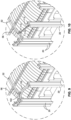
- a monorail member 200 is attached to selected ones of the buck stays 20 by generally inverted U-shaped hangers 202.
- the hangers 202 include an outboard vertical leg 202a and an inboard vertical leg 202b connected to one another by a horizontal leg 202c.
- the monorail 200 is connected rigidly to the inboard leg 202b and supports a travelling hoist 60 of the variety discussed previously.
- the relative lengths of the legs 202a and 202b can be predetermined so as to accommodate varying height requirements that may be needed from one regenerator structure to another.
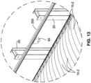
- FIG. 13 is similar to the embodiment depicted in FIG. 12 except that the monorail 200 is connected rigidly to an inboard face of the buck stays 20.
Landscapes
- Engineering & Computer Science (AREA)
- Chemical & Material Sciences (AREA)
- Structural Engineering (AREA)
- Organic Chemistry (AREA)
- Materials Engineering (AREA)
- Mechanical Engineering (AREA)
- Civil Engineering (AREA)
- Automation & Control Theory (AREA)
- Transportation (AREA)
- Furnace Housings, Linings, Walls, And Ceilings (AREA)
- Glass Melting And Manufacturing (AREA)
- Jib Cranes (AREA)
- Vertical, Hearth, Or Arc Furnaces (AREA)
Description
- The embodiments disclosed herein relate generally to methods and apparatus for constructing refractory structures associated with glass furnaces.
- In the manufacturing process for making glass, raw materials including sand, lime, soda ash and other ingredients are fed into a furnace, sometimes called a glass tank. The raw materials are subjected to temperature above about 2,800°F in the glass furnace which causes the raw materials to melt and thereby form a molten bed of glass that exits the glass furnace for further downstream processing into glass products.
- The most common way of heating the glass furnace is through the combustion of a hydrocarbon fuel source, such as natural gas or oil. The hydrocarbon fuel is mixed with combustion air inside the furnace and combusted to thereby transfer the combustion heat energy to the raw materials and glass melt prior to exiting the furnace.
- In order to improve the thermal efficiency of the combustion process, the combustion air used to combust the fuel is preheated by means of regenerator structures. More specifically, a supply of combustion air is preheated in a honeycombed pack of checker bricks contained within the interior of the regenerator structure. Fresh combustion air is drawn up through the pack of heated checker bricks in the regenerator structure and preheated by means of heat transfer. The pre-heated combustion air may then be mixed with the fuel, combusted. Waste combustion gas exits the glass furnace and passes through a second regenerator structure. As the waste gasses pass through the second regenerator the checkers in the pack are heated by means of heat transferred from the waste gas. After a predetermined time has elapsed (e.g., after about 15-30 minutes), the process cycle is reversed so that the checker bricks in one of the regenerator structures that were being heated by heat transfer with the waste gas are then used to preheat the fresh combustion air while the checker bricks in the other regenerator structures that were used to preheat the combustion air are then re-heated by heat transfer with the waste combustion gas. See in this regard,
U.S. Patent No. 3,326,541 . - The current process for building glass furnace refractory structures, e.g., regenerators, glass furnaces, fore hearths and the like, is very labor intensive taking many weeks as it requires the placement of hundreds of thousands of refractory bricks that may be individually coated with mortar and positioned or in some cases essentially dry set with minimal (if any) mortar. As is well known in the glass making industry, the joints associated with the bricks of the furnace refractory structures are the weakest part of the structure and are consequently more readily susceptible to degradation by the corrosive hot gasses passing therethrough. As the brick joints begin to erode, the walls forming the refractory structure face increased attack as the corrosive gasses begin to condense and dissolve the refractory materials forming the bricks thereby weakening the structure. As the structure becomes weakened, the glass furnace itself may become compromised and fail which could then require a complete shut down and rebuilding operation.
WO2012078036 A2 describes the rebuilding of a coke oven. - It can be appreciated therefore, that if the refractory structures could be fabricated from larger refractory blocks, then fewer joints would ensue thereby prolonging the regenerator structure's useful life and minimizing down time due to rebuilding. However, while large refractory blocks can be fabricated by pressing, molding or casting a refractory material, it is problematic to install such blocks during construction of a large-scale refractory structure.
- In addition to the problems noted above, many of the components of the refractory structure, e.g., checker bricks used in glass regenerator structures, need to be replaced near or at the end of their useful life in order to maintain optimal production efficiencies. It is currently difficult to replace such components, e.g., the checker bricks, when it may be desired for them to do so.
- What has been needed therefore are improvements in apparatus and methods whereby refractory structures may be efficiently and economically constructed and/or re-built. It is towards providing such improvements that the embodiments of the present invention are directed.
- In general, the embodiments disclosed herein are directed toward methods and apparatus for constructing a refractory structures, e.g., glass furnace regenerators, glass furnace systems such as glass furnace refiners, and the like having walls formed of refractory block and buck stays externally supporting the walls. According to the invention, an apparatus according to claim 1 is provided.
- According to other embodiments, a method for constructing a regenerator structure according to claim 11 is provided.
- These and other aspects and advantages of the present invention will become more clear after careful consideration is given to the following detailed description of the preferred exemplary embodiments thereof.
- The disclosed embodiments of the present invention will be better and more completely understood by referring to the following detailed description of exemplary non-limiting illustrative embodiments in conjunction with the drawings of which:
-
FIG. 1 is a perspective view of a regenerator structure showing an apparatus in accordance with an embodiment of the present invention; -
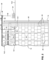
FIG. 2 is a partial end elevation view of the regenerator structure as depicted inFIG. 1 ; -
FIG. 3A is a perspective view of a regenerator structure prior to installation of apparatus in accordance with an embodiment of the present invention; -
FIG. 3B is an enlarged perspective view of an end of the regenerator structure depicted inFIG. 3A ; -
FIG. 3C is an enlarged perspective view similar toFIG. 3A but showing an installation sequence for the overhead crane apparatus; -
FIG. 3D is an enlarged perspective view similar toFIG. 3C but showing the overhead crane apparatus completely installed; -
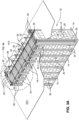
FIG. 4 is a perspective view of a cross-fired glass furnace system showing the apparatus in accordance with other embodiments of the present invention; -
FIGS. 5 and 6 are a side and end elevational views, respectively, of the upper portion of the glass furnace system depicted inFIG. 4 ; -
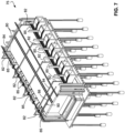
FIG. 7 is a perspective view of the glass furnace section of the system depicted inFIG. 4 ; -
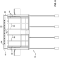
FIG. 8 is an end elevational view of the glass furnace section depicted inFIG. 7 ; -
FIGS. 9-13 are respective schematic perspective views of alternative support arrangements according to other embodiments of the invention. - Accompanying
FIG. 1 schematically depicts a perspective view of aregenerator structure 10 showing anoverhead crane apparatus 50 in accordance with an embodiment of the present invention. As shown, theregenerator structure 10 is constructed of large pre-cast refractor blocks (a few of which are identified by reference numeral 12) stacked on afoundation 14 to thereby form side andend walls regenerator structure 10 is used in operative combination with a glass furnace (not shown). Theregenerator structure 10 generally depicted in the accompanying figures is of a type used for side-fired glass furnaces. However, the attributes of the embodiments of the invention to be described herein are equally applicable to other glass furnace designs, e.g. end-fired glass furnaces. - The
regenerator structure 10 includes a series of ports 10-1 which are used to introduce pre-heated combustion air into the glass furnace (not shown) or to exhaust combustion gas from the furnace depending on the operational cycle. The top of theregenerator structure 10 is capped with crowns (a representative few of which are noted by reference numeral 10-2). An operator platform 10-3 typically is provided near the ports 10-1. Thewalls FIGS. 3A and3B , the buck stays 20 are compressively held against the walls by means oftie rods 22 extending between opposed pairs of buck stays 20 both latitudinally and longitudinally relative to theregenerator structure 10. -
FIG. 1 depicts a state whereby thewalls refractory blocks 12 and the checker bricks (a supply of which stacked on the platform 10-3 is denoted inFIG. 1 by reference numeral 24) are being stacked within the interior space of theregenerator structure 10. Theapparatus 50 in the state shown inFIG. 1 has thus been employed to install therefractory blocks 12 when forming thewalls checker bricks 24 within the interior defined bysuch walls regenerator structure 10 so as to permit access into its interior space. - The
overhead crane apparatus 50 in accordance with the invention is depicted as including laterally spaced-apart upright pairs of upright support beams 52 and across-support beam 54 spanning the distance therebetween. Afoundation beam 55 extends between and is rigidly attached (e.g., by welding) to an adjacent pair of buck stays 20 so as to structurally support the upright andcross-support beams - The cross-support beams 52, 54 dependently support a pair of runway beams 56 between which is connected a travelling
bridge beam 58. Thebridge beam 58 includes an overhead travelling hoist 60. As is shown inFIG. 2 , the runway beams 56 are supported in a cantilever manner by the end-most upright andcross-support beams wall 18 of theregenerator structure 10 thereby enabling access to the stacked supply ofchecker bricks 24 on the platform 10-3. - Suitable operator controlled motors (not shown) are provided with the
bridge beam 58 to allow it to reciprocally travel along the runway beams 56 in a longitudinal direction of the regenerator structure (i.e., in the direction of arrow A1 inFIG. 1 ). Similarly, operator controlled motors (not shown) are provided with the hoist 60 to allow it to travel reciprocally along the bridge beam in a latitudinal direction of the regenerator structure 10 (i.e., in a direction of arrow A2 inFIG. 1 ). The hoist 60 is connected to asuitable lifting sling 62 to allow the stacked supply ofchecker bricks 24 to be lifted up and into the interior of theregenerator structure 10, e.g., by suitably operating thebridge beam 58 and hoist 60 so as to travel in the directions of arrows A1 and A2 while simultaneously causing the hoist 62 to raise or lower the checker bricks 24 (i.e., in a direction transverse to arrows A1 and A2). In such a manner, therefore, the checker bricks within theregenerator structure 10 may be replaced. It will be appreciated that the operation as described above will also allow therefractory blocks 12 to be installed as may be needed. -
FIGS. 3A-3D show a sequence by which theoverhead crane apparatus 50 may be assembled relative to an existingregenerator structure 10. As was previously noted, the buck stays 20 are compressively held against therefractory blocks 12 forming thewalls tie rods 22.FIGS. 3A and3B therefore show an existingregenerator structure 10 with thetie rods 22 in place. As is shown inFIG. 3C , thetie rods 22 have been removed and afoundation beam 55,upright support beam 54 andcross-support beam 56 installed as described previously. The particular sequence of removing thetie rods 22 and installation of thefoundation beam 55,upright support beam 52 andcross-support beam 54 is not critical provided that there is no structural interference therebetween. Thus, thetie rods 22 can be removed before or after installation of thefoundation beam 55,upright support beam 52 andcross-support beam 54 although it is typically preferred that thetie rods 22 be removed first as this ensures that they will not structurally interfere with any of the later installed beams. -
FIG. 3D shows the runway beams 56 having been installed by connection to the cross-support beams 54. Although not shown inFIG. 3D , thebridge beam 58 with the hoist 60 operatively connected thereto may likewise be installed onto the runway beams 56. Thereafter, the installation of therefractory blocks 12 and/orchecker bricks 24 may proceed in the manner as previously described. - A cross-fired
glass furnace system 70 is depicted inFIGS. 4-6 as being comprised of a central glass furnace structure 75 (e.g., a float furnace) and opposed pairs ofregenerator structures 10, 10' operatively interacting with thefurnace structure 75. Each of theregenerator structures 10, 10' are as described previously with reference toFIGS. 1-3D but are substantial mirror images of one another. Thus, corresponding structure described above with reference toregenerator 10 is shown by the same reference numeral in regenerator 10', but with a prime (`) identifier. Thus, separate explanations of such corresponding structures for theregenerators 10, 10' will not be repeated. - The
glass furnace structure 75, like theregenerators 10, 10', includes vertically oriented buck stays 80. The overhead crane apparatus employed for theglass furnace structure 75 is depicted as including laterally spaced-apart upright pairs of upright support beams 82 and across-support beam 84 spanning the distance therebetween. Afoundation beam 85 extends between and is rigidly attached (e.g., by welding) to an adjacent pair of buck stays 80 so as to structurally support the upright andcross-support beams - The cross-support beams 82, 84 dependently support a pair of runway beams 86 between which is connected a travelling
bridge beam 88. Thebridge beam 88 includes an overhead travelling hoist 90. The runway beams 86 are preferably supported in a cantilever manner by the end-most upright andcross-support beams furnace structure 75 thereby enabling access to structural components to be hoisted by the travelling hoist 90. - Suitable operator controlled motors (not shown) are provided with the
bridge beam 88 to allow it to reciprocally travel along the runway beams 86 in a longitudinal direction of the regenerator structure (i.e., in the direction of arrow A1 inFIG. 4 ). Similarly, operator controlled motors (not shown) are provided with the hoist 90 to allow it to travel reciprocally along the bridge beam in a latitudinal direction of the furnace structure 75 (i.e., in a direction of arrow A2 inFIG. 4 ). -
FIGS. 9 and 10 depict alternative embodiments for supporting the cross-supports beams 52, 52' of theregenerator structures 10, 10', respectively, and/or the cross-support beams 82 of theglass furnace structure 75. In this regard,FIGS. 9 and 10 are depicted in relationship to supporting the cross-support beams 52 theregenerator structure 10, but the disclosed embodiments are equally applicable to the regenerator structure 10' and theglass furnace structure 75. - As shown in
FIG. 9 , thecross-support beam 52 may be attached to anarched support member 100 which extends between and is rigidly connected to (e.g., via welding) an adjacent pair of buck stays 20. Thecross-support beam 52 may be connected directly to an apex region of thearched support member 100. Alternatively, as depicted inFIG. 9 , apedestal support 102 may be provided extending upwardly from the apex region of thearched support member 100 to which an end of thecross-support beam 52 is attached. - In a similar manner,
FIG. 10 shows another embodiment whereby a pair of upwardlyconvergent support members convergent support members convergent support members pedestal support 114 which in turn is connected to thecross-support support beam 52. - Another embodiment is depicted in
FIG. 11 whereby a buck stay extension member 20-1 is rigidly fixed to (e.g., via welding) an upper terminal end of the buck stays. Thecross-support beam 54 may therefore be rigidly fixed to opposing pairs of such extension members 20-1 so as to span the distance across the regenerator structure. The runway beams 56 may therefore be connected directly to the cross-support beams 54. According to the embodiment depicted inFIG. 11 , therefore, the use of upright support beams 52 and foundation beams 55 is not necessarily required. - Accompanying
FIGS. 12 and13 depict embodiments of the invention which employ a monorail system. In this regard, as shown inFIG. 12 , amonorail member 200 is attached to selected ones of the buck stays 20 by generally invertedU-shaped hangers 202. As shown, thehangers 202 include an outboardvertical leg 202a and an inboardvertical leg 202b connected to one another by ahorizontal leg 202c. Themonorail 200 is connected rigidly to theinboard leg 202b and supports a travelling hoist 60 of the variety discussed previously. The relative lengths of thelegs -
FIG. 13 is similar to the embodiment depicted inFIG. 12 except that themonorail 200 is connected rigidly to an inboard face of the buck stays 20. - Although the embodiments have been described in relation to a cross-fired glass furnace system, the principles of the invention may likewise be embodied in any glass furnace design, such as float furnaces, end-fired furnaces, unit melters with recuperators and electric furnaces with shelf, sidewall or bottom electrodes.
- It will therefore be understood that the description provided herein is presently considered to be the most practical and preferred embodiments of the invention. Thus, the invention is not to be limited to the disclosed embodiments, but by the scope of the appended claims.
Claims (11)
- An apparatus for constructing a glass furnace regenerator structure (10) formed of large pre-cast refractory blocks (12) stacked on a foundation (14) to form end and side walls (16, 18) and vertically oriented buck stays (20) externally supporting the walls (16, 18) and an interior comprised of checker bricks (24), the apparatus comprising an overhead crane assembly (50) attached to and supported by the buck stays (20), wherein the apparatus further comprises:opposed pairs of upright supports connected to at least a respective one of the vertically oriented buck stays (20), and cross-support beams (54) latitudinally spanning the glass furnace regenerator structure (10) and connected between respective pairs of the supports,wherein the pairs of upright supports comprise:a plurality of foundation beams (55) rigidly installed between respective adjacent pairs of buck stays (20);pairs of upright support beams (52) each supported by a respective one of the foundation beams, andwherein the overhead crane assembly (50) comprises:a pair of raceway beams (56), each raceway beam (56) longitudinally extending relative to the regenerator structure and dependently supported by the cross-support beams (54); anda hoist assembly moveably mounted to the raceway beam,
anda bridge beam (58) moveably mounted to the pair of raceway beams for reciprocal movements therealong in a longitudinal direction of the regenerator structure; whereinthe hoist assembly (60) is moveably mounted to the bridge beam (58) for reciprocal movements therealong in a latitudinal direction of the regenerator structure, wherein one end portion of the raceway beam (56) is supported in a cantilever manner by a respective pair of support beams (52) and cross-support beam (54) and so as to extend beyond a respective end of the regenerator structure (10). - The apparatus according to claim 1, wherein the pairs of supports comprise an arch support extending between and connected to an adjacent pair of the buck stays, wherein the cross-support beams (54) are attached to an apex of the arch support (100).
- The apparatus according to claim 1 or 2, wherein the pairs of supports comprise a pair of upwardly convergent supports (110, 112) extending between and connected to an adjacent pair of the buck stays (20), wherein the cross-support beams (54) are attached to an apex of the convergent supports (110, 112).
- The apparatus according to any preceding claim, further comprising buck stay extension members (20-1) rigidly connected to an upper terminal end of predetermined buck stays (20), and cross-support beams (54) spanning the regenerator structure between respective pairs of the buck stay extension members (20-1).
- The apparatus according to any preceding claim, wherein the hoist assembly comprises a monorail (200) attached to predetermined ones of the buck stays (20).
- The apparatus according claim 5, wherein the monorail (200) is rigidly connected to an inboard surface of the predetermined ones of the buck stays (20).
- The apparatus according to claim 6, further comprising a hanger member (202) having one leg (202a) attached rigidly to the predetermined ones of the buck stays (20), and another leg (202b) rigidly attached to the monorail.
- The apparatus according to claim 7, wherein the hanger member (202) is generally U-shaped.
- The apparatus according to any preceding claim, wherein the regenerator structure further includes a port (10-1) and an operator platform (10-3) below the port (10-1), and wherein the foundation beams (55) are rigidly positioned between the respective pairs of buck stays (20) at or above the operator platform (10-3).
- The apparatus according to any preceding claim, wherein the regenerator structure (10) comprises a glass furnace structure.
- A method of constructing a crane assembly relative to a glass furnace regenerator structure (10) formed of large pre-cast refractory blocks (12) stacked on a foundation (14) to form end and side walls (16, 18) and vertically oriented buck stays (20) externally supporting the side walls (16, 18) and an interior comprised of checker bricks (24), the method comprising:(i) connecting opposed pairs of supports to a respective one of vertically oriented buck stays (20);(ii) latitudinally spanning the refractory structure with cross-support beams (54) connected between respective pairs of the upright supports; and(iii) supporting an overhead crane assembly (50) by the cross-support beams (54),wherein step (i) comprises:(ia) rigidly installing a plurality of foundation beams (55) between respective adjacent pairs of buck stays (20); and(ib) supporting pairs of upright support beams (52) by a respective one of the foundation beams (55), andwherein the method further comprises:(a) installing a pair of raceway beams (56) which longitudinally extend relative to the regenerator structure (10) and are dependently supported by the cross-support beams (54);(b) moveably mounting a bridge beam (58) to the pair of raceway beams (56) for reciprocal movements therealong in a longitudinal direction of the regenerator structure (10); and(c) moveably mounting a hoist (60) to the bridge beam (58) for reciprocal movements therealong in a latitudinal direction of the regenerator structure (10), wherein step (a) comprises installing the raceway beams (56) so that one end portion of the raceway beams (56) is supported in a cantilever manner by a respective pair of support beams (52) and a cross-support beam (54) to thereby cause the one end of the raceway beams (56) to extend beyond a respective end of the regenerator structure (10).
Applications Claiming Priority (4)
| Application Number | Priority Date | Filing Date | Title |
|---|---|---|---|
| US201462053403P | 2014-09-22 | 2014-09-22 | |
| US201562111275P | 2015-02-03 | 2015-02-03 | |
| GB201503121A GB201503121D0 (en) | 2015-02-03 | 2015-02-25 | Methods and apparatus for constructing glass furnace structures |
| PCT/US2015/051141 WO2016048860A1 (en) | 2014-09-22 | 2015-09-21 | Methods and apparatus for constructing glass furnace structures |
Publications (2)
| Publication Number | Publication Date |
|---|---|
| EP3197814A1 EP3197814A1 (en) | 2017-08-02 |
| EP3197814B1 true EP3197814B1 (en) | 2024-09-04 |
Family
ID=55525100
Family Applications (1)
| Application Number | Title | Priority Date | Filing Date |
|---|---|---|---|
| EP15771467.6A Active EP3197814B1 (en) | 2014-09-22 | 2015-09-21 | Methods and apparatus for constructing glass furnace structures |
Country Status (12)
| Country | Link |
|---|---|
| US (2) | US10227220B2 (en) |
| EP (1) | EP3197814B1 (en) |
| JP (1) | JP6728189B2 (en) |
| KR (1) | KR102463508B1 (en) |
| CN (1) | CN106715344A (en) |
| AU (1) | AU2015321653B9 (en) |
| BR (1) | BR112017005493B1 (en) |
| ES (1) | ES2989951T3 (en) |
| FI (1) | FI3197814T3 (en) |
| MX (1) | MX389237B (en) |
| PL (1) | PL3197814T3 (en) |
| WO (1) | WO2016048860A1 (en) |
Families Citing this family (3)
| Publication number | Priority date | Publication date | Assignee | Title |
|---|---|---|---|---|
| US12122646B2 (en) * | 2018-06-22 | 2024-10-22 | Fosbel, Inc. | Methods and apparatus for constructing glass furnace refractory structures |
| US12359277B2 (en) * | 2019-11-11 | 2025-07-15 | Maftec Co., Ltd. | Annealing furnace, method of constructing annealing furnace, and structure for prefabrication |
| UA129379C2 (en) * | 2020-06-28 | 2025-04-02 | Вібра Машіненфабрік Шультхайс Гмбх Унд Ко. | Heavy load vortex internal apparatus for handling plastic granular material and method related thereto |
Family Cites Families (34)
| Publication number | Priority date | Publication date | Assignee | Title |
|---|---|---|---|---|
| US1320386A (en) | 1919-11-04 | Shield or auxiliary wall for furnaces | ||
| US1320387A (en) | 1919-11-04 | Open-hearth furnace | ||
| US1639138A (en) * | 1925-10-30 | 1927-08-16 | Liptak Michael | Furnace wall |
| US2281951A (en) * | 1938-09-20 | 1942-05-05 | American Arch Co | Furnace wall |
| US2585238A (en) | 1948-10-23 | 1952-02-12 | Universal Oil Prod Co | Method and apparatus for effecting the fluidized catalytic conversion of a reactant stream |
| US3049200A (en) * | 1959-03-06 | 1962-08-14 | Combustion Eng | Panel mounting for steel cased furnaces |
| US3072080A (en) | 1960-06-28 | 1963-01-08 | United States Steel Corp | Mason's accessory for repairing furnace roofs |
| US3203682A (en) * | 1963-11-20 | 1965-08-31 | Joseph J Kerin | Open hearth furnace |
| US3203376A (en) * | 1963-12-30 | 1965-08-31 | Combustion Eng | Buckstay arrangement for furnace walls |
| CH410108A (en) | 1964-05-25 | 1966-03-31 | Bbc Brown Boveri & Cie | Gas pressure switch |
| US3399046A (en) * | 1964-12-29 | 1968-08-27 | Levi S. Longenecker | Furnace suspended skimmer wall |
| US3326541A (en) | 1965-10-24 | 1967-06-20 | Harbison Walker Refractories | Glass tank structure with a regenerator chamber |
| US3379177A (en) * | 1966-12-29 | 1968-04-23 | Combustion Eng | Buckstay connection for furnace walls |
| US3869996A (en) * | 1972-09-02 | 1975-03-11 | Viktor Mikhailovich Panferov | Method and apparatus for extending life period of furnace roofs |
| US4137037A (en) | 1977-10-06 | 1979-01-30 | Libbey-Owens-Ford Company | Method of repairing furnace roofs during heat-up |
| US4240234A (en) * | 1978-12-20 | 1980-12-23 | Foster Wheeler Energy Corporation | Adjustable buckstay system for vapor generators or the like |
| US4219326A (en) * | 1979-04-09 | 1980-08-26 | Libbey-Owens-Ford Company | Glass melting furnace structure |
| US4369032A (en) * | 1979-07-02 | 1983-01-18 | Inland Steel Company | Reheat furnace |
| CN2095715U (en) | 1991-01-20 | 1992-02-12 | 中国矿业大学 | Stringed curved probability sieve |
| US5645395A (en) | 1995-06-06 | 1997-07-08 | Huang; Hsin-Tsung | Building crane apparatus climbable on building walls |
| JP3339348B2 (en) * | 1997-01-29 | 2002-10-28 | 住友金属工業株式会社 | Blast furnace bottom furnace construction method |
| US5941445A (en) | 1997-11-24 | 1999-08-24 | Bethlehem Steel Corporation | Apparatus for refurbishing a coke oven doorjamb |
| US6814012B2 (en) * | 2002-10-11 | 2004-11-09 | Hatch Associates Ltd. | Furnace binding and adjustment systems |
| CN2905715Y (en) | 2006-03-24 | 2007-05-30 | 中国第一冶金建设有限责任公司 | Refractory material transport device of industrial furnace building project |
| US7827689B2 (en) * | 2007-01-16 | 2010-11-09 | Vanocur Refractories, L.L.C. | Coke oven reconstruction |
| WO2010071388A1 (en) | 2008-12-17 | 2010-06-24 | Compañia Vidriera, S.A. De C.V. | Method for constructing a monolithic refractory concrete furnace intended for the production of glass |
| WO2012078036A2 (en) * | 2010-12-09 | 2012-06-14 | Heatteq Refractories Holding B.V. | Prefabricated coke oven wall, heavy lift construction for lifting and moving such a prefabricated coke oven wall, and method for repairing an existing coke oven battery |
| JP5679511B2 (en) | 2010-12-16 | 2015-03-04 | サン技研株式会社 | heating furnace |
| CN203474296U (en) | 2013-08-09 | 2014-03-12 | 河北冀凯铸业有限公司 | Automatic lifting device for furnace cover of pit type resistance furnace |
| CN103884184B (en) | 2014-03-27 | 2015-10-21 | 中国三冶集团有限公司 | The resistance to material of a kind of vertical continuous annealing furnace, liner installation method and movable mounting platform |
| CN203772011U (en) | 2014-03-27 | 2014-08-13 | 中国三冶集团有限公司机械安装工程公司 | Movable mounting platform for refractory materials and liner of vertical continuous annealing furnace |
| GB201500703D0 (en) * | 2014-11-14 | 2015-03-04 | Fosbel Inc | Monolithic refractory crown and rider arches for glass furnace regenerators and glass furnace regenerators including the same |
| GB201503159D0 (en) * | 2015-02-25 | 2015-04-08 | Fosbel Inc | Methods and apparatus for constructing glass furnace structures |
| GB201503127D0 (en) * | 2015-02-03 | 2015-04-08 | Fosbel Inc | Methods and apparatus for constructing glass furnace structures |
-
2015
- 2015-09-21 US US14/859,820 patent/US10227220B2/en active Active
- 2015-09-21 ES ES15771467T patent/ES2989951T3/en active Active
- 2015-09-21 EP EP15771467.6A patent/EP3197814B1/en active Active
- 2015-09-21 FI FIEP15771467.6T patent/FI3197814T3/en active
- 2015-09-21 BR BR112017005493-0A patent/BR112017005493B1/en active IP Right Grant
- 2015-09-21 KR KR1020177011123A patent/KR102463508B1/en active Active
- 2015-09-21 WO PCT/US2015/051141 patent/WO2016048860A1/en not_active Ceased
- 2015-09-21 AU AU2015321653A patent/AU2015321653B9/en active Active
- 2015-09-21 JP JP2017535615A patent/JP6728189B2/en active Active
- 2015-09-21 MX MX2017003670A patent/MX389237B/en unknown
- 2015-09-21 CN CN201580050954.6A patent/CN106715344A/en active Pending
- 2015-09-21 PL PL15771467.6T patent/PL3197814T3/en unknown
-
2019
- 2019-01-30 US US16/262,171 patent/US11180350B2/en active Active
Also Published As
| Publication number | Publication date |
|---|---|
| MX2017003670A (en) | 2017-08-14 |
| JP6728189B2 (en) | 2020-07-22 |
| WO2016048860A1 (en) | 2016-03-31 |
| BR112017005493A2 (en) | 2017-12-19 |
| PL3197814T3 (en) | 2025-02-03 |
| KR20170065577A (en) | 2017-06-13 |
| US20190161325A1 (en) | 2019-05-30 |
| AU2015321653A1 (en) | 2017-04-27 |
| FI3197814T3 (en) | 2024-11-27 |
| MX389237B (en) | 2025-03-20 |
| AU2015321653B2 (en) | 2019-11-21 |
| BR112017005493B1 (en) | 2023-01-10 |
| US20160083230A1 (en) | 2016-03-24 |
| JP2017534566A (en) | 2017-11-24 |
| CN106715344A (en) | 2017-05-24 |
| US10227220B2 (en) | 2019-03-12 |
| AU2015321653B9 (en) | 2019-12-12 |
| US11180350B2 (en) | 2021-11-23 |
| KR102463508B1 (en) | 2022-12-09 |
| ES2989951T3 (en) | 2024-11-28 |
| EP3197814A1 (en) | 2017-08-02 |
Similar Documents
| Publication | Publication Date | Title |
|---|---|---|
| US11180350B2 (en) | Methods and apparatus for constructing glass furnace structures | |
| US9963372B2 (en) | Monolithic refractory crown and rider arches for glass furnace regenerators and glass furnace regenerators including the same | |
| US10407333B2 (en) | Methods and apparatus for constructing glass furnace structures | |
| US10294085B2 (en) | Methods and apparatus for constructing glass furnace structures | |
| EP3416920B1 (en) | Glass furnace regenerators formed of one-piece load-bearing wall blocks | |
| HK1234718B (en) | Methods and apparatus for constructing glass furnace structures | |
| HK1234718A1 (en) | Methods and apparatus for constructing glass furnace structures | |
| US20160231058A1 (en) | Integral self-supporting refractory checker brick modules for glass furnace regenerator structures, and methods of forming same | |
| US12122646B2 (en) | Methods and apparatus for constructing glass furnace refractory structures | |
| CN102492438A (en) | Method for replacing brackets of dry quenching furnace | |
| CN213396502U (en) | Novel tunnel kiln car masonry structure |
Legal Events
| Date | Code | Title | Description |
|---|---|---|---|
| STAA | Information on the status of an ep patent application or granted ep patent |
Free format text: STATUS: THE INTERNATIONAL PUBLICATION HAS BEEN MADE |
|
| PUAI | Public reference made under article 153(3) epc to a published international application that has entered the european phase |
Free format text: ORIGINAL CODE: 0009012 |
|
| STAA | Information on the status of an ep patent application or granted ep patent |
Free format text: STATUS: REQUEST FOR EXAMINATION WAS MADE |
|
| 17P | Request for examination filed |
Effective date: 20170418 |
|
| AK | Designated contracting states |
Kind code of ref document: A1 Designated state(s): AL AT BE BG CH CY CZ DE DK EE ES FI FR GB GR HR HU IE IS IT LI LT LU LV MC MK MT NL NO PL PT RO RS SE SI SK SM TR |
|
| AX | Request for extension of the european patent |
Extension state: BA ME |
|
| DAV | Request for validation of the european patent (deleted) | ||
| DAX | Request for extension of the european patent (deleted) | ||
| REG | Reference to a national code |
Ref country code: HK Ref legal event code: DE Ref document number: 1234718 Country of ref document: HK |
|
| STAA | Information on the status of an ep patent application or granted ep patent |
Free format text: STATUS: EXAMINATION IS IN PROGRESS |
|
| 17Q | First examination report despatched |
Effective date: 20211117 |
|
| GRAP | Despatch of communication of intention to grant a patent |
Free format text: ORIGINAL CODE: EPIDOSNIGR1 |
|
| STAA | Information on the status of an ep patent application or granted ep patent |
Free format text: STATUS: GRANT OF PATENT IS INTENDED |
|
| INTG | Intention to grant announced |
Effective date: 20240206 |
|
| GRAJ | Information related to disapproval of communication of intention to grant by the applicant or resumption of examination proceedings by the epo deleted |
Free format text: ORIGINAL CODE: EPIDOSDIGR1 |
|
| STAA | Information on the status of an ep patent application or granted ep patent |
Free format text: STATUS: EXAMINATION IS IN PROGRESS |
|
| GRAP | Despatch of communication of intention to grant a patent |
Free format text: ORIGINAL CODE: EPIDOSNIGR1 |
|
| STAA | Information on the status of an ep patent application or granted ep patent |
Free format text: STATUS: GRANT OF PATENT IS INTENDED |
|
| INTC | Intention to grant announced (deleted) | ||
| GRAS | Grant fee paid |
Free format text: ORIGINAL CODE: EPIDOSNIGR3 |
|
| INTG | Intention to grant announced |
Effective date: 20240701 |
|
| GRAA | (expected) grant |
Free format text: ORIGINAL CODE: 0009210 |
|
| STAA | Information on the status of an ep patent application or granted ep patent |
Free format text: STATUS: THE PATENT HAS BEEN GRANTED |
|
| AK | Designated contracting states |
Kind code of ref document: B1 Designated state(s): AL AT BE BG CH CY CZ DE DK EE ES FI FR GB GR HR HU IE IS IT LI LT LU LV MC MK MT NL NO PL PT RO RS SE SI SK SM TR |
|
| REG | Reference to a national code |
Ref country code: GB Ref legal event code: FG4D |
|
| REG | Reference to a national code |
Ref country code: CH Ref legal event code: EP |
|
| REG | Reference to a national code |
Ref country code: IE Ref legal event code: FG4D |
|
| REG | Reference to a national code |
Ref country code: DE Ref legal event code: R096 Ref document number: 602015089774 Country of ref document: DE |
|
| REG | Reference to a national code |
Ref country code: FI Ref legal event code: FGE |
|
| REG | Reference to a national code |
Ref country code: ES Ref legal event code: FG2A Ref document number: 2989951 Country of ref document: ES Kind code of ref document: T3 Effective date: 20241128 |
|
| REG | Reference to a national code |
Ref country code: LT Ref legal event code: MG9D |
|
| REG | Reference to a national code |
Ref country code: NL Ref legal event code: MP Effective date: 20240904 |
|
| PG25 | Lapsed in a contracting state [announced via postgrant information from national office to epo] |
Ref country code: NO Free format text: LAPSE BECAUSE OF FAILURE TO SUBMIT A TRANSLATION OF THE DESCRIPTION OR TO PAY THE FEE WITHIN THE PRESCRIBED TIME-LIMIT Effective date: 20241204 |
|
| PG25 | Lapsed in a contracting state [announced via postgrant information from national office to epo] |
Ref country code: GR Free format text: LAPSE BECAUSE OF FAILURE TO SUBMIT A TRANSLATION OF THE DESCRIPTION OR TO PAY THE FEE WITHIN THE PRESCRIBED TIME-LIMIT Effective date: 20241205 |
|
| PG25 | Lapsed in a contracting state [announced via postgrant information from national office to epo] |
Ref country code: BG Free format text: LAPSE BECAUSE OF FAILURE TO SUBMIT A TRANSLATION OF THE DESCRIPTION OR TO PAY THE FEE WITHIN THE PRESCRIBED TIME-LIMIT Effective date: 20240904 |
|
| PG25 | Lapsed in a contracting state [announced via postgrant information from national office to epo] |
Ref country code: LV Free format text: LAPSE BECAUSE OF FAILURE TO SUBMIT A TRANSLATION OF THE DESCRIPTION OR TO PAY THE FEE WITHIN THE PRESCRIBED TIME-LIMIT Effective date: 20240904 |
|
| PG25 | Lapsed in a contracting state [announced via postgrant information from national office to epo] |
Ref country code: HR Free format text: LAPSE BECAUSE OF FAILURE TO SUBMIT A TRANSLATION OF THE DESCRIPTION OR TO PAY THE FEE WITHIN THE PRESCRIBED TIME-LIMIT Effective date: 20240904 |
|
| PG25 | Lapsed in a contracting state [announced via postgrant information from national office to epo] |
Ref country code: RS Free format text: LAPSE BECAUSE OF FAILURE TO SUBMIT A TRANSLATION OF THE DESCRIPTION OR TO PAY THE FEE WITHIN THE PRESCRIBED TIME-LIMIT Effective date: 20241204 |
|
| PG25 | Lapsed in a contracting state [announced via postgrant information from national office to epo] |
Ref country code: RS Free format text: LAPSE BECAUSE OF FAILURE TO SUBMIT A TRANSLATION OF THE DESCRIPTION OR TO PAY THE FEE WITHIN THE PRESCRIBED TIME-LIMIT Effective date: 20241204 Ref country code: NO Free format text: LAPSE BECAUSE OF FAILURE TO SUBMIT A TRANSLATION OF THE DESCRIPTION OR TO PAY THE FEE WITHIN THE PRESCRIBED TIME-LIMIT Effective date: 20241204 Ref country code: LV Free format text: LAPSE BECAUSE OF FAILURE TO SUBMIT A TRANSLATION OF THE DESCRIPTION OR TO PAY THE FEE WITHIN THE PRESCRIBED TIME-LIMIT Effective date: 20240904 Ref country code: HR Free format text: LAPSE BECAUSE OF FAILURE TO SUBMIT A TRANSLATION OF THE DESCRIPTION OR TO PAY THE FEE WITHIN THE PRESCRIBED TIME-LIMIT Effective date: 20240904 Ref country code: GR Free format text: LAPSE BECAUSE OF FAILURE TO SUBMIT A TRANSLATION OF THE DESCRIPTION OR TO PAY THE FEE WITHIN THE PRESCRIBED TIME-LIMIT Effective date: 20241205 Ref country code: BG Free format text: LAPSE BECAUSE OF FAILURE TO SUBMIT A TRANSLATION OF THE DESCRIPTION OR TO PAY THE FEE WITHIN THE PRESCRIBED TIME-LIMIT Effective date: 20240904 |
|
| REG | Reference to a national code |
Ref country code: AT Ref legal event code: MK05 Ref document number: 1720216 Country of ref document: AT Kind code of ref document: T Effective date: 20240904 |
|
| PG25 | Lapsed in a contracting state [announced via postgrant information from national office to epo] |
Ref country code: NL Free format text: LAPSE BECAUSE OF FAILURE TO SUBMIT A TRANSLATION OF THE DESCRIPTION OR TO PAY THE FEE WITHIN THE PRESCRIBED TIME-LIMIT Effective date: 20240904 |
|
| PG25 | Lapsed in a contracting state [announced via postgrant information from national office to epo] |
Ref country code: PT Free format text: LAPSE BECAUSE OF FAILURE TO SUBMIT A TRANSLATION OF THE DESCRIPTION OR TO PAY THE FEE WITHIN THE PRESCRIBED TIME-LIMIT Effective date: 20250106 Ref country code: IS Free format text: LAPSE BECAUSE OF FAILURE TO SUBMIT A TRANSLATION OF THE DESCRIPTION OR TO PAY THE FEE WITHIN THE PRESCRIBED TIME-LIMIT Effective date: 20250104 |
|
| PG25 | Lapsed in a contracting state [announced via postgrant information from national office to epo] |
Ref country code: SM Free format text: LAPSE BECAUSE OF FAILURE TO SUBMIT A TRANSLATION OF THE DESCRIPTION OR TO PAY THE FEE WITHIN THE PRESCRIBED TIME-LIMIT Effective date: 20240904 Ref country code: RO Free format text: LAPSE BECAUSE OF FAILURE TO SUBMIT A TRANSLATION OF THE DESCRIPTION OR TO PAY THE FEE WITHIN THE PRESCRIBED TIME-LIMIT Effective date: 20240904 |
|
| PG25 | Lapsed in a contracting state [announced via postgrant information from national office to epo] |
Ref country code: EE Free format text: LAPSE BECAUSE OF FAILURE TO SUBMIT A TRANSLATION OF THE DESCRIPTION OR TO PAY THE FEE WITHIN THE PRESCRIBED TIME-LIMIT Effective date: 20240904 Ref country code: AT Free format text: LAPSE BECAUSE OF FAILURE TO SUBMIT A TRANSLATION OF THE DESCRIPTION OR TO PAY THE FEE WITHIN THE PRESCRIBED TIME-LIMIT Effective date: 20240904 |
|
| PG25 | Lapsed in a contracting state [announced via postgrant information from national office to epo] |
Ref country code: CZ Free format text: LAPSE BECAUSE OF FAILURE TO SUBMIT A TRANSLATION OF THE DESCRIPTION OR TO PAY THE FEE WITHIN THE PRESCRIBED TIME-LIMIT Effective date: 20240904 |
|
| PG25 | Lapsed in a contracting state [announced via postgrant information from national office to epo] |
Ref country code: SK Free format text: LAPSE BECAUSE OF FAILURE TO SUBMIT A TRANSLATION OF THE DESCRIPTION OR TO PAY THE FEE WITHIN THE PRESCRIBED TIME-LIMIT Effective date: 20240904 |
|
| REG | Reference to a national code |
Ref country code: CH Ref legal event code: PL |
|
| PG25 | Lapsed in a contracting state [announced via postgrant information from national office to epo] |
Ref country code: LU Free format text: LAPSE BECAUSE OF NON-PAYMENT OF DUE FEES Effective date: 20240921 |
|
| REG | Reference to a national code |
Ref country code: DE Ref legal event code: R097 Ref document number: 602015089774 Country of ref document: DE |
|
| PG25 | Lapsed in a contracting state [announced via postgrant information from national office to epo] |
Ref country code: MC Free format text: LAPSE BECAUSE OF FAILURE TO SUBMIT A TRANSLATION OF THE DESCRIPTION OR TO PAY THE FEE WITHIN THE PRESCRIBED TIME-LIMIT Effective date: 20240904 |
|
| PG25 | Lapsed in a contracting state [announced via postgrant information from national office to epo] |
Ref country code: DK Free format text: LAPSE BECAUSE OF FAILURE TO SUBMIT A TRANSLATION OF THE DESCRIPTION OR TO PAY THE FEE WITHIN THE PRESCRIBED TIME-LIMIT Effective date: 20240904 |
|
| PLBE | No opposition filed within time limit |
Free format text: ORIGINAL CODE: 0009261 |
|
| STAA | Information on the status of an ep patent application or granted ep patent |
Free format text: STATUS: NO OPPOSITION FILED WITHIN TIME LIMIT |
|
| PG25 | Lapsed in a contracting state [announced via postgrant information from national office to epo] |
Ref country code: CH Free format text: LAPSE BECAUSE OF NON-PAYMENT OF DUE FEES Effective date: 20240930 |
|
| PG25 | Lapsed in a contracting state [announced via postgrant information from national office to epo] |
Ref country code: IE Free format text: LAPSE BECAUSE OF NON-PAYMENT OF DUE FEES Effective date: 20240921 |
|
| 26N | No opposition filed |
Effective date: 20250605 |
|
| P01 | Opt-out of the competence of the unified patent court (upc) registered |
Free format text: CASE NUMBER: UPC_APP_1438_3197814/2025 Effective date: 20250730 |
|
| PG25 | Lapsed in a contracting state [announced via postgrant information from national office to epo] |
Ref country code: SE Free format text: LAPSE BECAUSE OF FAILURE TO SUBMIT A TRANSLATION OF THE DESCRIPTION OR TO PAY THE FEE WITHIN THE PRESCRIBED TIME-LIMIT Effective date: 20240904 |
|
| PGFP | Annual fee paid to national office [announced via postgrant information from national office to epo] |
Ref country code: FI Payment date: 20250925 Year of fee payment: 11 |
|
| PGFP | Annual fee paid to national office [announced via postgrant information from national office to epo] |
Ref country code: DE Payment date: 20250929 Year of fee payment: 11 |
|
| PGFP | Annual fee paid to national office [announced via postgrant information from national office to epo] |
Ref country code: TR Payment date: 20250908 Year of fee payment: 11 Ref country code: PL Payment date: 20250905 Year of fee payment: 11 Ref country code: IT Payment date: 20250919 Year of fee payment: 11 |
|
| PGFP | Annual fee paid to national office [announced via postgrant information from national office to epo] |
Ref country code: BE Payment date: 20250929 Year of fee payment: 11 Ref country code: GB Payment date: 20250929 Year of fee payment: 11 |
|
| PGFP | Annual fee paid to national office [announced via postgrant information from national office to epo] |
Ref country code: FR Payment date: 20250925 Year of fee payment: 11 |
|
| PG25 | Lapsed in a contracting state [announced via postgrant information from national office to epo] |
Ref country code: CY Free format text: LAPSE BECAUSE OF FAILURE TO SUBMIT A TRANSLATION OF THE DESCRIPTION OR TO PAY THE FEE WITHIN THE PRESCRIBED TIME-LIMIT; INVALID AB INITIO Effective date: 20150921 |
|
| PGFP | Annual fee paid to national office [announced via postgrant information from national office to epo] |
Ref country code: ES Payment date: 20251001 Year of fee payment: 11 |
|
| PG25 | Lapsed in a contracting state [announced via postgrant information from national office to epo] |
Ref country code: HU Free format text: LAPSE BECAUSE OF FAILURE TO SUBMIT A TRANSLATION OF THE DESCRIPTION OR TO PAY THE FEE WITHIN THE PRESCRIBED TIME-LIMIT; INVALID AB INITIO Effective date: 20150921 |