EP3196985A1 - Electrical connection device and method for mounting an electrical connection device - Google Patents
Electrical connection device and method for mounting an electrical connection device Download PDFInfo
- Publication number
- EP3196985A1 EP3196985A1 EP17151739.4A EP17151739A EP3196985A1 EP 3196985 A1 EP3196985 A1 EP 3196985A1 EP 17151739 A EP17151739 A EP 17151739A EP 3196985 A1 EP3196985 A1 EP 3196985A1
- Authority
- EP
- European Patent Office
- Prior art keywords
- contact
- rotation device
- longitudinal axis
- rotation
- housing
- Prior art date
- Legal status (The legal status is an assumption and is not a legal conclusion. Google has not performed a legal analysis and makes no representation as to the accuracy of the status listed.)
- Granted
Links
Images


Classifications
-
- H—ELECTRICITY
- H01—ELECTRIC ELEMENTS
- H01R—ELECTRICALLY-CONDUCTIVE CONNECTIONS; STRUCTURAL ASSOCIATIONS OF A PLURALITY OF MUTUALLY-INSULATED ELECTRICAL CONNECTING ELEMENTS; COUPLING DEVICES; CURRENT COLLECTORS
- H01R13/00—Details of coupling devices of the kinds covered by groups H01R12/70 or H01R24/00 - H01R33/00
- H01R13/40—Securing contact members in or to a base or case; Insulating of contact members
- H01R13/42—Securing in a demountable manner
- H01R13/426—Securing by a separate resilient retaining piece supported by base or case, e.g. collar or metal contact-retention clip
-
- H—ELECTRICITY
- H01—ELECTRIC ELEMENTS
- H01R—ELECTRICALLY-CONDUCTIVE CONNECTIONS; STRUCTURAL ASSOCIATIONS OF A PLURALITY OF MUTUALLY-INSULATED ELECTRICAL CONNECTING ELEMENTS; COUPLING DEVICES; CURRENT COLLECTORS
- H01R13/00—Details of coupling devices of the kinds covered by groups H01R12/70 or H01R24/00 - H01R33/00
- H01R13/40—Securing contact members in or to a base or case; Insulating of contact members
-
- H—ELECTRICITY
- H01—ELECTRIC ELEMENTS
- H01R—ELECTRICALLY-CONDUCTIVE CONNECTIONS; STRUCTURAL ASSOCIATIONS OF A PLURALITY OF MUTUALLY-INSULATED ELECTRICAL CONNECTING ELEMENTS; COUPLING DEVICES; CURRENT COLLECTORS
- H01R13/00—Details of coupling devices of the kinds covered by groups H01R12/70 or H01R24/00 - H01R33/00
- H01R13/40—Securing contact members in or to a base or case; Insulating of contact members
- H01R13/42—Securing in a demountable manner
- H01R13/436—Securing a plurality of contact members by one locking piece or operation
- H01R13/4361—Insertion of locking piece perpendicular to direction of contact insertion
-
- H—ELECTRICITY
- H01—ELECTRIC ELEMENTS
- H01R—ELECTRICALLY-CONDUCTIVE CONNECTIONS; STRUCTURAL ASSOCIATIONS OF A PLURALITY OF MUTUALLY-INSULATED ELECTRICAL CONNECTING ELEMENTS; COUPLING DEVICES; CURRENT COLLECTORS
- H01R13/00—Details of coupling devices of the kinds covered by groups H01R12/70 or H01R24/00 - H01R33/00
- H01R13/46—Bases; Cases
- H01R13/502—Bases; Cases composed of different pieces
-
- H—ELECTRICITY
- H01—ELECTRIC ELEMENTS
- H01R—ELECTRICALLY-CONDUCTIVE CONNECTIONS; STRUCTURAL ASSOCIATIONS OF A PLURALITY OF MUTUALLY-INSULATED ELECTRICAL CONNECTING ELEMENTS; COUPLING DEVICES; CURRENT COLLECTORS
- H01R13/00—Details of coupling devices of the kinds covered by groups H01R12/70 or H01R24/00 - H01R33/00
- H01R13/64—Means for preventing incorrect coupling
- H01R13/645—Means for preventing incorrect coupling by exchangeable elements on case or base
-
- H—ELECTRICITY
- H01—ELECTRIC ELEMENTS
- H01R—ELECTRICALLY-CONDUCTIVE CONNECTIONS; STRUCTURAL ASSOCIATIONS OF A PLURALITY OF MUTUALLY-INSULATED ELECTRICAL CONNECTING ELEMENTS; COUPLING DEVICES; CURRENT COLLECTORS
- H01R43/00—Apparatus or processes specially adapted for manufacturing, assembling, maintaining, or repairing of line connectors or current collectors or for joining electric conductors
- H01R43/20—Apparatus or processes specially adapted for manufacturing, assembling, maintaining, or repairing of line connectors or current collectors or for joining electric conductors for assembling or disassembling contact members with insulating base, case or sleeve
-
- H—ELECTRICITY
- H01—ELECTRIC ELEMENTS
- H01R—ELECTRICALLY-CONDUCTIVE CONNECTIONS; STRUCTURAL ASSOCIATIONS OF A PLURALITY OF MUTUALLY-INSULATED ELECTRICAL CONNECTING ELEMENTS; COUPLING DEVICES; CURRENT COLLECTORS
- H01R2201/00—Connectors or connections adapted for particular applications
- H01R2201/26—Connectors or connections adapted for particular applications for vehicles
Definitions
- the invention relates to an electrical connection device.
- a device of this type can be used in electric vehicles circuits for example, and more particularly, in electrical power circuits such as those interconnecting with one another, in electric or hybrid vehicles, elements such as a battery, a motor, a voltage converter, etc.
- Such an electrical connection device comprises one or more contacts, or pins, mounted in a housing and electrically connected to one or more cables, or one or more busbars, for example.
- the contacts used in this kind of connection often have a rod or bar, having a portion with a cylindrical external surface of revolution about a longitudinal axis. If this cylindrical surface of rotation is inserted into a cavity of the housing of complementary shape, i.e. tubular and cylindrical of revolution, the contact having this cylindrical portion can potentially turn in its cavity, about its longitudinal axis. In this case, it may happen that another portion of the contact, intended to be connected to a busbar for example, is no longer oriented correctly to cooperate with and/or be connected to thereto.
- a purpose of the invention is to block the contact in an appropriate orientation for its mechanical or electrical connection with another element (busbar or cable, for example).
- another purpose is to obtain an orientation of the contact about the longitudinal axis of its cylindrical portion of revolution (inserted into the tubular cavity of the housing), which does not depend on the precision provided by an operator to reorient the contact in its tubular cavity.
- the first portion has a cylindrical external surface of revolution about a longitudinal axis and is inserted into the tubular cavity of the housing.
- the second portion extends outside the tubular cavity and includes an orientation zone, with an external surface that is not completely cylindrical of revolution about the longitudinal axis.
- the second portion comprises at least one zone (referred to as the "orientation zone” in this document, but this zone can have another function in addition to orienting the contact about the longitudinal axis) whose external surface is not completely symmetrical, and at least not symmetrical in revolution, about the longitudinal axis.
- connection device comprises an anti-rotation device.
- This anti-rotation device is displaceable in translation along a placement direction, up to a final position (in which the electrical connection device can be connected to at least a busbar or a cable).
- the placement direction of anti-rotation device is substantially perpendicular to the longitudinal axis of the first portion of contact.
- the anti-rotation device has at least one surface complementary to the external surface of the orientation zone. This complementary surface abuts the external surface of the orientation zone, when the anti-rotation device is in final position and when the contact is oriented in an operating position, i.e. in the desired position or orientation (around the longitudinal axis) for its connection to at least one other element (busbar or cable, for example).
- the surface complementary to the external surface of the orientation zone and this external surface of the orientation zone are substantially parallel and/or in contact with one another.
- the electrical connection device may further comprise one or more of the following features, each considered independently of one another or in combination with one or more others:
- the invention concerns a method for mounting an electrical connection device, in which
- the anti-rotation device moves the contact in rotation to this position when the anti-rotation device is placed in its final position.
- FIG. 1 shows an exemplary connection device 1 according to the invention.
- This connection device essentially comprises a housing 2, two contacts 3, an anti-rotation device 4 and two electrical wires 5.
- the housing 2 and the anti-rotation device 4 consist of an electrically insulating material. They are, for example, moulded from a plastic material.
- the housing 2 has two tubular cavities 6 extending about a longitudinal axis L, perpendicularly to a flange 7. Each tubular cavity 6 passes longitudinally through a housing body 8 and extends, beyond the flange 7, at the level of a sleeve 9.
- Shielding 10 is placed in the housing body 8 around the cavities 6 and spring thereof to form a collar 11 extending substantially in a plane perpendicular to the longitudinal axis L.
- This collar 11 is intended to be compressed between the flange 7 and an electrically conductive support (not represented) whereon the connection device 1 will be mounted.
- the collar 11 is intended to establish an electrical contact with this support.
- a seal 12 is also mounted on the connection device 1 to achieve a watertight barrier between the flange 7 and this support.
- tubular cavities 6 and the contacts 3 lodged therein are respectively two in number, but the invention may be applied to connection devices having a single contact or more than two contacts.
- the electric wires 5 are electrically connected (e.g. crimped) on electric terminals (not visible in the figures), inserted into cavities formed in the housing 2.
- the electric wires 5 exit through openings 13 in the housing 2, between the contacts 3.
- the contacts 3 consist of a conductive material. For example, they are machined (bar turning) from a bar of copper alloy.
- the contacts 3 extend along a longitudinal axis L. They have several successive portions along this longitudinal axis L.
- a first portion 14 whose external surface 15 is cylindrical of revolution about the longitudinal axis and a second portion 16 which has an orientation zone 17 whose external surface 18 is not cylindrical of revolution about the longitudinal axis L can be defined.
- the second portion 16 of each contact 3 is flattened and has two orientation zones 17 symmetrical with respect to one another relative to a plane comprising the longitudinal axis of the first portion 14 of each contact 3.
- Each of these orientation zones 17 have a substantially flat external surface 18.
- the second portion 16 of each contact 3 has a bore for passing means to secure a cable or a busbar.
- a reinforcing ring 20 is crimped in this passage.
- the first portion 14 is intended to be inserted into one of the tubular cavities 6 of the housing 2.
- the first portion 14 is provided with an O-ring 34 mounted in a groove and ensuring a watertight seal between each contact 3 and its cavity 6.
- the second portion 16 is intended to be connected electrically to a cable or busbar.
- each second portion 16 projects from the flange 7 and the cavity 6 into which the corresponding contact 3 is inserted.
- the contact 3 can assume any angular orientation about its longitudinal axis.
- an anti-rotation device 4 is mounted on the connection device 1.
- the overall dimensions of the anti-rotation device 4 are such that it can be placed inside the sealed zone (limited by the lips of the seal 12 and a limited shielded zone). It has a hollow body 21, from which two wings 22 extend outwardly.
- the hollow body 21 comprises a cavity 23 which extends in the longitudinal direction L, when the anti-rotation device 4 is mounted on the connection device 1.
- the hollow body 21 is intended to be inserted between the second portions 16 of the contacts 3, and in the example described here, between the sleeves 9.
- the shape and the elasticity of the hollow body 21 are such that the anti-rotation device 4 can be clipped onto the sleeves 9.
- the hollow body 21 can be deformed so as to substantially bring the curved zones 24 towards one another, these zones intended complementarily to conform to the shape of the external surface of the sleeves 9, when the anti-rotation device 4 is in place on the connection device 1.
- These elastic means 26 exert an action on the contacts 3 tending to press the surfaces of the wings 22 in abutment against the orientation zones 17, when the anti-rotation device 4 is in final position.
- These elastic means 26 also cooperate with the tubular external surface of the sleeves 9.
- the hollow body 21 has two notches 27, or gutters, aligned in a direction substantially perpendicular to the wings 22. Each of these notches 27 is intended to accommodate, guide and protect an electric wire 5.
- Each wing 22 has a surface 28, or zone, complementary to an orientation zone 17 of a contact 3. In the example presented here, this surface 28 is flat and oriented perpendicularly to the placement and mounting direction T of the anti-rotation device 4 on the connection device 1.
- Each wing 22, also has a notch 29 to fix the corresponding contact 3 in a specific position, along the longitudinal direction L, in relation to the anti-rotation device 4. This notch 29 has a rounded and stepped shape so as to match the shape of the reinforcing ring 20.
- the curved surface of the notch 29 is open towards the outside of the connection device 4 and blocks the movement of the contact 3 in the housing 2 in the direction of the flange 7.
- the anti-rotation device comprises a rib 30, on each side of the hollow body 21, under each of the wings 22 in order to the fix the anti-rotation device 4 along the longitudinal axis L on the edge of each of the sleeves 9.
- the position of the contacts 3 along their respective longitudinal axis can thus be precisely defined and respected when mounting the contacts 3 in the housing 2.
- the ribs 29 are placed behind a bulging portion of the orientation zone 17.
- the ribs 29 thus also block the movements of the contacts 3 in the housing 2 in the direction tending to spread the orientation zones 17 of the flange 7.
- the notches 29 and the ribs 30 thus form the positioning means 31 for the contacts 3 along the longitudinal axis L.
- the anti-rotation device 4 is brought close to the connection device 1.
- the electric wires 5 are inserted to the centre of the hollow body 21, therethrough.
- the anti-rotation device 4 is placed substantially above the end of the sleeves 9 and of the orientation zones 17 of the contacts 3 ( figure 4a ).
- the anti-rotation device 4 is moved perpendicularly to the longitudinal axis L of the contacts 3 and in parallel to the flange 7 by bringing the hollow body 21 between the second portions 16 of the contacts 3.
- the elastic means 26 exert a resistance that corresponds to a force that increases to a maximum, then decreases. A "Go-no-go" effect is obtained.
- the anti-rotation device 4 is moved with sufficient force to overcome this maximum force and the anti-rotation device 4 automatically moves into the final position through elastic means 26; or this force is insufficient and the anti-rotation device 4 is not at all maintained on the connection device 1.
- the anti-rotation device 4 therefore cannot be incorrectly positioned on the connection device 1.
- the maximum amount of force is greater than the force required to move the contact 3 in rotation about the longitudinal axis L of any angular position to its operating position. The movement of the anti-rotation device 4 to its final position thus involves the automatic correction of the orientation and the position of the contact 3.
- the anti-rotation device 4 if the orientation zones 17 are not properly oriented and positioned about and along the longitudinal axis of the contacts 3, the flat surface 28 of wings 22 cooperate, in a complementarily manner, with the surfaces of the orientation zones 17, on the one hand, and the ribs 30 and the notches 29 cooperate with the edge 33 of the ends of the sleeves 9 and with the reinforcement rings 20 ( figure 4b ), respectively, on the other hand.
- the anti-rotation device 4 is in place on the connection device 1, the contacts 3 are fixed in rotation and in translation by the anti-rotation device 4 (see figures 4c , 5a and 5b ).
- the anti-rotation device 4 comprises wings 22 oriented at 90°, about their respective longitudinal L, in relation to one another.
- their flat surfaces 28 are perpendicular to each other.
- the principle for the placement and control of the orientation and position of the contacts 3 is, however, the same as that described above in relation to figures 4a to 4c .
- the contacts 3 and their respective orientation zones 17 are oriented at 90° in relation to one another about the longitudinal axis L.
- the anti-rotation device 4 instead of being positioned partly on the sleeves 9 and partly on the contacts 3, as explained above, may be positioned only on the sleeves 9 or only on the contacts 3.
Landscapes
- Engineering & Computer Science (AREA)
- Manufacturing & Machinery (AREA)
- Details Of Connecting Devices For Male And Female Coupling (AREA)
- Connector Housings Or Holding Contact Members (AREA)
Abstract
Description
- The invention relates to an electrical connection device. A device of this type can be used in electric vehicles circuits for example, and more particularly, in electrical power circuits such as those interconnecting with one another, in electric or hybrid vehicles, elements such as a battery, a motor, a voltage converter, etc.
- Such an electrical connection device comprises one or more contacts, or pins, mounted in a housing and electrically connected to one or more cables, or one or more busbars, for example. In this case, the contacts used in this kind of connection often have a rod or bar, having a portion with a cylindrical external surface of revolution about a longitudinal axis. If this cylindrical surface of rotation is inserted into a cavity of the housing of complementary shape, i.e. tubular and cylindrical of revolution, the contact having this cylindrical portion can potentially turn in its cavity, about its longitudinal axis. In this case, it may happen that another portion of the contact, intended to be connected to a busbar for example, is no longer oriented correctly to cooperate with and/or be connected to thereto.
- This incorrect orientation can lead to complications when securing or connecting the contact to another conductive element (e.g. a busbar or a cable). An additional, often manual, operation is necessary to rotate the contact and give it in an orientation suitable for connection with the other element. However, this orientation operation, which may be imprecise and does not completely solve the problems, can also result in a loss of productivity.
- A purpose of the invention is to block the contact in an appropriate orientation for its mechanical or electrical connection with another element (busbar or cable, for example). Optionally, another purpose is to obtain an orientation of the contact about the longitudinal axis of its cylindrical portion of revolution (inserted into the tubular cavity of the housing), which does not depend on the precision provided by an operator to reorient the contact in its tubular cavity.
- At least one of these purposes is at least partly achieved with an electrical connection device having
- a housing with at least one tubular cavity, and
- at least one contact having a first and a second portion.
- The first portion has a cylindrical external surface of revolution about a longitudinal axis and is inserted into the tubular cavity of the housing. The second portion extends outside the tubular cavity and includes an orientation zone, with an external surface that is not completely cylindrical of revolution about the longitudinal axis. In other words, the second portion comprises at least one zone (referred to as the "orientation zone" in this document, but this zone can have another function in addition to orienting the contact about the longitudinal axis) whose external surface is not completely symmetrical, and at least not symmetrical in revolution, about the longitudinal axis.
- Furthermore, the connection device comprises an anti-rotation device. This anti-rotation device is displaceable in translation along a placement direction, up to a final position (in which the electrical connection device can be connected to at least a busbar or a cable). The placement direction of anti-rotation device is substantially perpendicular to the longitudinal axis of the first portion of contact. The anti-rotation device has at least one surface complementary to the external surface of the orientation zone. This complementary surface abuts the external surface of the orientation zone, when the anti-rotation device is in final position and when the contact is oriented in an operating position, i.e. in the desired position or orientation (around the longitudinal axis) for its connection to at least one other element (busbar or cable, for example). When the anti-rotation device is in final position and the contact is oriented in an operating position, the surface complementary to the external surface of the orientation zone and this external surface of the orientation zone are substantially parallel and/or in contact with one another.
- In this manner, it is possible to block the orientation of the orientation zone about the longitudinal axis according to at least one predefined direction. Furthermore, if the contact is not properly oriented about the longitudinal axis, it is possible, during the placement of the anti-rotation device, to mechanically interact with the orientation zone in order to change its orientation about the longitudinal axis. In other words, during the placement of the anti-rotation device, if a contact with which it must interact is not correctly oriented, the anti-rotation device turns it and when the anti-rotation device is in final position, the respective surfaces of the anti-rotation device and of the second portion of contact cooperate to maintain the contact blocked in rotation in the desired position.
- The electrical connection device may further comprise one or more of the following features, each considered independently of one another or in combination with one or more others:
- the second portion of the contact comprises two orientation zones each having an external surface that is not completely cylindrical of revolution, these two orientation zones being symmetrical to each other in relation to a plane comprising the longitudinal axis of the first portion of the contact;
- the external surface, not completely cylindrical of revolution, of the two orientation zones is flat and the anti-rotation device comprises at least one surface, complementary to the equally flat external surface of the orientation zones;
- the anti-rotation device is secured to the contact by elastic means, causing the anti-rotation device to press the complementary surface of the external surface of the orientation zone against it when the anti-rotation device is in final position;
- the elastic means cooperate with a tubular external surface of the housing;
- during the displacement of the anti-rotation device in the placement direction, toward its final position, the elastic means exert a resistance which corresponds to a force that increases to a maximum, then decreases;
- the maximum of the force is greater than the force needed to move the contact in rotation about the longitudinal axis in any angular position to its operating position;
- the anti-rotation device includes positioning means that cooperate with the contact to position the anti-rotation device in relation to the housing in the longitudinal direction; and
- the anti-rotation device includes a groove for guiding a conductive wire emerging from the housing.
- According to another aspect, the invention concerns a method for mounting an electrical connection device, in which
- a housing is provided, at least one contact and an anti-rotation device, and
- a first portion of contact is inserted into a tubular cavity of the housing extending along a longitudinal axis, and in which
- the anti-rotation device is fastened to the housing by displacing it in translation in a placement direction, substantially perpendicular to the longitudinal axis, up to a final position in which the anti-rotation device abuts on a second portion of the contact located outside the tubular cavity and blocks the rotation of contact about the longitudinal axis in an operating position.
- Optionally, in this method, if the contact is not oriented about the longitudinal axis in the operating position, the anti-rotation device moves the contact in rotation to this position when the anti-rotation device is placed in its final position.
- Other features and advantages of the invention will emerge on reading the detailed description and studying the accompanying drawings:
-
figure 1 schematically shows, in perspective, an exemplary connection device according to the invention; -
figure 2 schematically shows, in perspective, the detail of the connection device shown infigure 1 ; -
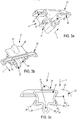
figures 3a to 3c show, in perspective from different angles, an anti-rotation device intended to be mounted on a connection device such as that offigures 1 and 2 ; -
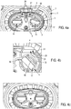
figures 4a to 4c schematically show the implementation and mounting the anti-rotation device offigures 3a to 3c , on the connection device offigures 1 and 2 as seen from the front thereof; -
figures 5a and 5b schematically show, in perspective, from different angles, the anti-rotation device of the previous figures; and -
figures 6a and 6b schematically show, in perspective, a second embodiment of the anti-rotation device according to the invention, in pre-assembly position and final position, respectively, on a connection device similar to that offigures 1 and 2 . - In these figures, the same references are used to designate identical or similar elements.
-
Figure 1 shows anexemplary connection device 1 according to the invention. This connection device essentially comprises ahousing 2, twocontacts 3, ananti-rotation device 4 and twoelectrical wires 5. - The
housing 2 and theanti-rotation device 4 consist of an electrically insulating material. They are, for example, moulded from a plastic material. In the example illustrated infigures 1 a to 6b, thehousing 2 has twotubular cavities 6 extending about a longitudinal axis L, perpendicularly to aflange 7. Eachtubular cavity 6 passes longitudinally through ahousing body 8 and extends, beyond theflange 7, at the level of asleeve 9.Shielding 10 is placed in thehousing body 8 around thecavities 6 and spring thereof to form acollar 11 extending substantially in a plane perpendicular to the longitudinal axis L. Thiscollar 11 is intended to be compressed between theflange 7 and an electrically conductive support (not represented) whereon theconnection device 1 will be mounted. Thecollar 11 is intended to establish an electrical contact with this support. Aseal 12 is also mounted on theconnection device 1 to achieve a watertight barrier between theflange 7 and this support. - In the example shown and described in this document, the
tubular cavities 6 and thecontacts 3 lodged therein are respectively two in number, but the invention may be applied to connection devices having a single contact or more than two contacts. - The
electric wires 5 are electrically connected (e.g. crimped) on electric terminals (not visible in the figures), inserted into cavities formed in thehousing 2. Theelectric wires 5 exit throughopenings 13 in thehousing 2, between thecontacts 3. - The
contacts 3 consist of a conductive material. For example, they are machined (bar turning) from a bar of copper alloy. Thecontacts 3 extend along a longitudinal axis L. They have several successive portions along this longitudinal axis L. Notably, afirst portion 14 whoseexternal surface 15 is cylindrical of revolution about the longitudinal axis and asecond portion 16 which has anorientation zone 17 whoseexternal surface 18 is not cylindrical of revolution about the longitudinal axis L can be defined. More particularly, in the example described in relation tofigures 1a to 5b , thesecond portion 16 of eachcontact 3 is flattened and has twoorientation zones 17 symmetrical with respect to one another relative to a plane comprising the longitudinal axis of thefirst portion 14 of eachcontact 3. Each of theseorientation zones 17 have a substantially flatexternal surface 18. Thesecond portion 16 of eachcontact 3 has a bore for passing means to secure a cable or a busbar. A reinforcingring 20 is crimped in this passage. - The
first portion 14 is intended to be inserted into one of thetubular cavities 6 of thehousing 2. Here, thefirst portion 14 is provided with an O-ring 34 mounted in a groove and ensuring a watertight seal between eachcontact 3 and itscavity 6. Thesecond portion 16 is intended to be connected electrically to a cable or busbar. - As shown in
figure 2 , eachsecond portion 16 projects from theflange 7 and thecavity 6 into which thecorresponding contact 3 is inserted. As can be seen infigure 2 , owing to the symmetry of revolution of thefirst portion 14 and the internal surface of thecavity 6 into which thiscontact 3 is inserted, thecontact 3 can assume any angular orientation about its longitudinal axis. - In order to define and fix this angular orientation, an
anti-rotation device 4 is mounted on theconnection device 1. - This
anti-rotation device 4 is described in more detail in relation tofigures 3a to 3c . Advantageously, the overall dimensions of theanti-rotation device 4 are such that it can be placed inside the sealed zone (limited by the lips of theseal 12 and a limited shielded zone). It has ahollow body 21, from which twowings 22 extend outwardly. Thehollow body 21 comprises acavity 23 which extends in the longitudinal direction L, when theanti-rotation device 4 is mounted on theconnection device 1. Thehollow body 21 is intended to be inserted between thesecond portions 16 of thecontacts 3, and in the example described here, between thesleeves 9. The shape and the elasticity of thehollow body 21 are such that theanti-rotation device 4 can be clipped onto thesleeves 9. Thehollow body 21 can be deformed so as to substantially bring thecurved zones 24 towards one another, these zones intended complementarily to conform to the shape of the external surface of thesleeves 9, when theanti-rotation device 4 is in place on theconnection device 1. Thesecurved zones hollow body 21 that link them, thus formelastic means 26. These elastic means 26 exert an action on thecontacts 3 tending to press the surfaces of thewings 22 in abutment against theorientation zones 17, when theanti-rotation device 4 is in final position. These elastic means 26 also cooperate with the tubular external surface of thesleeves 9. - The
hollow body 21 has twonotches 27, or gutters, aligned in a direction substantially perpendicular to thewings 22. Each of thesenotches 27 is intended to accommodate, guide and protect anelectric wire 5. Eachwing 22 has asurface 28, or zone, complementary to anorientation zone 17 of acontact 3. In the example presented here, thissurface 28 is flat and oriented perpendicularly to the placement and mounting direction T of theanti-rotation device 4 on theconnection device 1. Eachwing 22, also has anotch 29 to fix thecorresponding contact 3 in a specific position, along the longitudinal direction L, in relation to theanti-rotation device 4. Thisnotch 29 has a rounded and stepped shape so as to match the shape of the reinforcingring 20. The curved surface of thenotch 29 is open towards the outside of theconnection device 4 and blocks the movement of thecontact 3 in thehousing 2 in the direction of theflange 7. Furthermore, the anti-rotation device comprises arib 30, on each side of thehollow body 21, under each of thewings 22 in order to the fix theanti-rotation device 4 along the longitudinal axis L on the edge of each of thesleeves 9. The position of thecontacts 3 along their respective longitudinal axis can thus be precisely defined and respected when mounting thecontacts 3 in thehousing 2. As can be seen infigures 5a and 5b , theribs 29 are placed behind a bulging portion of theorientation zone 17. Theribs 29 thus also block the movements of thecontacts 3 in thehousing 2 in the direction tending to spread theorientation zones 17 of theflange 7. Thenotches 29 and theribs 30 thus form the positioning means 31 for thecontacts 3 along the longitudinal axis L. - The assembly of the anti-rotation device on the connection device is illustrated in
figures 4a to 4c . - Initially, the
anti-rotation device 4 is brought close to theconnection device 1. Theelectric wires 5 are inserted to the centre of thehollow body 21, therethrough. Theanti-rotation device 4 is placed substantially above the end of thesleeves 9 and of theorientation zones 17 of the contacts 3 (figure 4a ). Theanti-rotation device 4 is moved perpendicularly to the longitudinal axis L of thecontacts 3 and in parallel to theflange 7 by bringing thehollow body 21 between thesecond portions 16 of thecontacts 3. During this movement, in the placement direction T, towards its final position, the elastic means 26 exert a resistance that corresponds to a force that increases to a maximum, then decreases. A "Go-no-go" effect is obtained. So, either theanti-rotation device 4 is moved with sufficient force to overcome this maximum force and theanti-rotation device 4 automatically moves into the final position throughelastic means 26; or this force is insufficient and theanti-rotation device 4 is not at all maintained on theconnection device 1. Theanti-rotation device 4 therefore cannot be incorrectly positioned on theconnection device 1. Furthermore, the maximum amount of force is greater than the force required to move thecontact 3 in rotation about the longitudinal axis L of any angular position to its operating position. The movement of theanti-rotation device 4 to its final position thus involves the automatic correction of the orientation and the position of thecontact 3. During the placement of theanti-rotation device 4, if theorientation zones 17 are not properly oriented and positioned about and along the longitudinal axis of thecontacts 3, theflat surface 28 ofwings 22 cooperate, in a complementarily manner, with the surfaces of theorientation zones 17, on the one hand, and theribs 30 and thenotches 29 cooperate with theedge 33 of the ends of thesleeves 9 and with the reinforcement rings 20 (figure 4b ), respectively, on the other hand. When theanti-rotation device 4 is in place on theconnection device 1, thecontacts 3 are fixed in rotation and in translation by the anti-rotation device 4 (seefigures 4c ,5a and 5b ). - According to a variant illustrated in
figures 6a and 6b , theanti-rotation device 4 compriseswings 22 oriented at 90°, about their respective longitudinal L, in relation to one another. In other words, theirflat surfaces 28 are perpendicular to each other. The principle for the placement and control of the orientation and position of thecontacts 3 is, however, the same as that described above in relation tofigures 4a to 4c . When theanti-rotation device 4 is in final position (figure 6b ), thecontacts 3 and theirrespective orientation zones 17 are oriented at 90° in relation to one another about the longitudinal axis L. - According to non-illustrated variants, the
anti-rotation device 4, instead of being positioned partly on thesleeves 9 and partly on thecontacts 3, as explained above, may be positioned only on thesleeves 9 or only on thecontacts 3.
Claims (11)
- Electrical connection device including- a housing (2) with at least one tubular cavity (6), and- at least one contact (3) having a first (14) portion and a second (16) portion, the first portion (14) having a cylindrical external surface of revolution (15) about a longitudinal axis (L) and being inserted into the tubular cavity (6) of the housing (2) and the second portion (16) extending outside the tubular cavity (6) and having an orientation zone (17), with an external surface that is not completely cylindrical of revolution (18) about the longitudinal axis (L),wherein it further comprises an anti-rotation device (4), displaceable in translation in a placement direction (T), substantially perpendicular to the longitudinal axis (L) of the first portion (14) of the contact (3), up to a final position, and having at least one surface (32) complementary to the external surface (18) of the orientation zone (17) and abutting thereon when the anti-rotation device (4) is in final position and the contact (3) is oriented in an operating position.
- The device according to claim 1, wherein the second portion (16) of the contact (3) comprises two orientation zones (17) each having an external surface (18) that is not completely cylindrical of revolution, these two orientation zones (17) being symmetrical to each other in relation to a plane including the longitudinal axis (L) of the first portion (14) of the contact (3).
- The device according to claim 2, wherein the external surface (18), not completely cylindrical of revolution of each of the two orientation zones (17), is flat and the anti-rotation device (4) comprises at least one surface (28) complementary to the external surface (18) of the orientation zones (17), which is also flat.
- The device according to any one of the preceding claims, wherein the anti-rotation device (4) is secured to the connection device (1) by elastic means (26), causing the anti-rotation device (4) to press against the complementary surface (28) of the external surface (18) of the orientation zone (17) abutting thereon when the anti-rotation device (4) is in final position.
- The device according to claim 4, wherein the elastic means (26) cooperate with a tubular external surface of the housing (2).
- The device according to claims 4 or 5, wherein, during the displacement of the anti-rotation device (4) according to the placement direction, toward its final position, the elastic means (26) exert a resistance corresponding to a force that increases to a maximum, then decreases.
- The device according to claim 6, wherein the maximum of the force is greater than the force required to move the contact (3) in rotation about the longitudinal axis (L) of any angular position to its operating position.
- The device according to any one of the preceding claims, wherein the anti-rotation device (4) comprises positioning means (31) that cooperate with the contact (3) to position anti-rotation device (4) in relation to the housing (2) in the longitudinal direction (L).
- The device according to any one of the preceding claims, wherein the anti-rotation device (4) comprises a gutter (27) to guide a conductive wire (5) emerging from the housing (2).
- A method for mounting an electrical connection device, wherein- a housing (2) and at least one contact (3) is provided, and- a first portion (14) of the contact (3) is inserted into a tubular cavity (6) of the housing (2) extending along a longitudinal axis (L),wherein the anti-rotation device (4) is fastened to the housing (2) by moving it in translation in a placement direction (T), substantially perpendicular to the longitudinal axis (L), up to a final position in which the anti-rotation device (4) abuts on a stop on a second portion (16) of the contact (3) located outside the tubular cavity (6) and blocks the rotation of contact (3) about the longitudinal axis (L) in an operating position.
- The method according to claim 10, in which, if the contact (3) is not oriented about the longitudinal axis (L) in the operating position, the anti-rotation device (4) moves the contact (3) in rotation to this position when the anti-rotation device (4) is placed in its final position.
Applications Claiming Priority (1)
| Application Number | Priority Date | Filing Date | Title |
|---|---|---|---|
| FR1650456A FR3046884B1 (en) | 2016-01-20 | 2016-01-20 | ELECTRICAL CONNECTION DEVICE AND METHOD FOR MOUNTING AN ELECTRICAL CONNECTION DEVICE |
Publications (2)
| Publication Number | Publication Date |
|---|---|
| EP3196985A1 true EP3196985A1 (en) | 2017-07-26 |
| EP3196985B1 EP3196985B1 (en) | 2019-04-03 |
Family
ID=56069032
Family Applications (1)
| Application Number | Title | Priority Date | Filing Date |
|---|---|---|---|
| EP17151739.4A Active EP3196985B1 (en) | 2016-01-20 | 2017-01-17 | Electrical connection device and method for mounting an electrical connection device |
Country Status (5)
| Country | Link |
|---|---|
| US (1) | US10038270B2 (en) |
| EP (1) | EP3196985B1 (en) |
| JP (1) | JP6888875B2 (en) |
| CN (1) | CN106992378B (en) |
| FR (1) | FR3046884B1 (en) |
Families Citing this family (6)
| Publication number | Priority date | Publication date | Assignee | Title |
|---|---|---|---|---|
| CN107645101B (en) * | 2017-08-09 | 2020-09-29 | 中车青岛四方机车车辆股份有限公司 | Vehicle end electric connecting device and vehicle end connecting equipment of rail train |
| DE102018100831A1 (en) * | 2018-01-16 | 2019-07-18 | Dr. Ing. H.C. F. Porsche Aktiengesellschaft | Charging plug for electric cars and its manufacture |
| JP6922838B2 (en) * | 2018-05-16 | 2021-08-18 | 住友電装株式会社 | connector |
| US10770825B2 (en) | 2018-10-24 | 2020-09-08 | Aptiv Technologies Limited | Electrical contact spring and electrical assembly including same |
| EP3945644A1 (en) * | 2020-07-30 | 2022-02-02 | Rosenberger Hochfrequenztechnik GmbH & Co. KG | Front plate for a housing of a control device, housing assembly, connecting arrangement and vehicle |
| CN217306878U (en) * | 2021-12-01 | 2022-08-26 | 上海峰飞航空科技有限公司 | Aircraft and connector thereof |
Citations (1)
| Publication number | Priority date | Publication date | Assignee | Title |
|---|---|---|---|---|
| DE102013102647A1 (en) * | 2013-03-14 | 2014-09-18 | Fele Gmbh & Co. Kg | Connecting bushing for a housing of an electrical component, in particular of a rechargeable battery, and method for mounting a connection feedthrough |
Family Cites Families (8)
| Publication number | Priority date | Publication date | Assignee | Title |
|---|---|---|---|---|
| US1420675A (en) * | 1918-09-04 | 1922-06-27 | Gen Lead Batteries Company | Storage-battery terminal |
| US1472391A (en) * | 1920-06-15 | 1923-10-30 | Ford Bruce | Terminal seal for storage batteries |
| US4775604A (en) * | 1986-05-08 | 1988-10-04 | Globe-Union Inc. | Method and apparatus for sealing a battery terminal post |
| US7575476B2 (en) * | 2007-08-01 | 2009-08-18 | Tyco Electronics Corporation | Power distribution module and header assembly therefor |
| US8192212B2 (en) * | 2008-08-04 | 2012-06-05 | Fci Automotive Holding | Electrical connector system with temporarily blocking during unmating of two connectors |
| WO2011124563A1 (en) * | 2010-04-09 | 2011-10-13 | Fci Automotive Holding | Electrical connector system |
| CN104247167B (en) * | 2012-04-05 | 2017-03-08 | 莫列斯公司 | High Power Electrical Connectors |
| JP6056720B2 (en) * | 2013-09-18 | 2017-01-11 | 住友電装株式会社 | Connector for equipment |
-
2016
- 2016-01-20 FR FR1650456A patent/FR3046884B1/en active Active
-
2017
- 2017-01-12 US US15/404,239 patent/US10038270B2/en active Active
- 2017-01-17 EP EP17151739.4A patent/EP3196985B1/en active Active
- 2017-01-18 CN CN201710074912.7A patent/CN106992378B/en active Active
- 2017-01-19 JP JP2017007329A patent/JP6888875B2/en active Active
Patent Citations (1)
| Publication number | Priority date | Publication date | Assignee | Title |
|---|---|---|---|---|
| DE102013102647A1 (en) * | 2013-03-14 | 2014-09-18 | Fele Gmbh & Co. Kg | Connecting bushing for a housing of an electrical component, in particular of a rechargeable battery, and method for mounting a connection feedthrough |
Also Published As
| Publication number | Publication date |
|---|---|
| CN106992378B (en) | 2020-08-11 |
| US10038270B2 (en) | 2018-07-31 |
| FR3046884A1 (en) | 2017-07-21 |
| CN106992378A (en) | 2017-07-28 |
| FR3046884B1 (en) | 2018-01-26 |
| US20170207564A1 (en) | 2017-07-20 |
| JP6888875B2 (en) | 2021-06-16 |
| EP3196985B1 (en) | 2019-04-03 |
| JP2017130453A (en) | 2017-07-27 |
Similar Documents
| Publication | Publication Date | Title |
|---|---|---|
| EP3196985B1 (en) | Electrical connection device and method for mounting an electrical connection device | |
| EP2117080B1 (en) | Harness connection member | |
| US8317548B2 (en) | Electrical connector | |
| AU2015204300B2 (en) | Terminal block with ground strap, spring force terminals, and screw lug terminal | |
| DE202010006401U1 (en) | Electrical module connection of a motor vehicle | |
| CN109586129B (en) | Plug device and power distribution system | |
| FI65874C (en) | ELMATNINGANORDNING | |
| DE202010006400U1 (en) | Electrical module connection of a motor vehicle | |
| CN102792523B (en) | Plug connector | |
| US9906003B1 (en) | Device and method for splicing shielded wire cables | |
| WO2014194997A1 (en) | Electrical connection system for a shock absorber rod | |
| ES2683892T3 (en) | Electrical connection device with a retaining means to position a contact spring in a base state | |
| EP4421999A1 (en) | Touch protection cover, connection member, module connector and battery system | |
| US20150068801A1 (en) | Quick one-way connection system | |
| DE102021106844A1 (en) | System and contact device with mismating protection | |
| EP2462607B1 (en) | A switching device | |
| US8314670B2 (en) | Switching device | |
| KR101830272B1 (en) | Connector combined with fuse holder | |
| US11320121B2 (en) | Method for assembling an adjustable automotive luminous device | |
| JP7482832B2 (en) | Stranded wire connection tool | |
| US10076046B2 (en) | Arrangement for making contact with a printed circuit board | |
| EP1376005A2 (en) | Vehicle lamp | |
| EP3772138A1 (en) | Clippable interconnection module and associated connection cord | |
| CN113972512A (en) | Protective cover for a high-current plug connector | |
| EP0694219B1 (en) | Snap-on connector for electric lines |
Legal Events
| Date | Code | Title | Description |
|---|---|---|---|
| PUAI | Public reference made under article 153(3) epc to a published international application that has entered the european phase |
Free format text: ORIGINAL CODE: 0009012 |
|
| STAA | Information on the status of an ep patent application or granted ep patent |
Free format text: STATUS: THE APPLICATION HAS BEEN PUBLISHED |
|
| AK | Designated contracting states |
Kind code of ref document: A1 Designated state(s): AL AT BE BG CH CY CZ DE DK EE ES FI FR GB GR HR HU IE IS IT LI LT LU LV MC MK MT NL NO PL PT RO RS SE SI SK SM TR |
|
| AX | Request for extension of the european patent |
Extension state: BA ME |
|
| STAA | Information on the status of an ep patent application or granted ep patent |
Free format text: STATUS: REQUEST FOR EXAMINATION WAS MADE |
|
| 17P | Request for examination filed |
Effective date: 20180126 |
|
| RBV | Designated contracting states (corrected) |
Designated state(s): AL AT BE BG CH CY CZ DE DK EE ES FI FR GB GR HR HU IE IS IT LI LT LU LV MC MK MT NL NO PL PT RO RS SE SI SK SM TR |
|
| STAA | Information on the status of an ep patent application or granted ep patent |
Free format text: STATUS: EXAMINATION IS IN PROGRESS |
|
| 17Q | First examination report despatched |
Effective date: 20180531 |
|
| GRAP | Despatch of communication of intention to grant a patent |
Free format text: ORIGINAL CODE: EPIDOSNIGR1 |
|
| STAA | Information on the status of an ep patent application or granted ep patent |
Free format text: STATUS: GRANT OF PATENT IS INTENDED |
|
| RIC1 | Information provided on ipc code assigned before grant |
Ipc: H01R 13/436 20060101AFI20181011BHEP Ipc: H01R 13/645 20060101ALI20181011BHEP Ipc: H01R 13/426 20060101ALI20181011BHEP |
|
| INTG | Intention to grant announced |
Effective date: 20181105 |
|
| RAP1 | Party data changed (applicant data changed or rights of an application transferred) |
Owner name: APTIV TECHNOLOGIES LIMITED |
|
| GRAS | Grant fee paid |
Free format text: ORIGINAL CODE: EPIDOSNIGR3 |
|
| GRAA | (expected) grant |
Free format text: ORIGINAL CODE: 0009210 |
|
| STAA | Information on the status of an ep patent application or granted ep patent |
Free format text: STATUS: THE PATENT HAS BEEN GRANTED |
|
| AK | Designated contracting states |
Kind code of ref document: B1 Designated state(s): AL AT BE BG CH CY CZ DE DK EE ES FI FR GB GR HR HU IE IS IT LI LT LU LV MC MK MT NL NO PL PT RO RS SE SI SK SM TR |
|
| REG | Reference to a national code |
Ref country code: GB Ref legal event code: FG4D |
|
| REG | Reference to a national code |
Ref country code: CH Ref legal event code: EP Ref country code: AT Ref legal event code: REF Ref document number: 1116910 Country of ref document: AT Kind code of ref document: T Effective date: 20190415 |
|
| REG | Reference to a national code |
Ref country code: DE Ref legal event code: R096 Ref document number: 602017002969 Country of ref document: DE |
|
| REG | Reference to a national code |
Ref country code: IE Ref legal event code: FG4D |
|
| REG | Reference to a national code |
Ref country code: NL Ref legal event code: MP Effective date: 20190403 |
|
| REG | Reference to a national code |
Ref country code: LT Ref legal event code: MG4D |
|
| REG | Reference to a national code |
Ref country code: AT Ref legal event code: MK05 Ref document number: 1116910 Country of ref document: AT Kind code of ref document: T Effective date: 20190403 |
|
| PG25 | Lapsed in a contracting state [announced via postgrant information from national office to epo] |
Ref country code: NL Free format text: LAPSE BECAUSE OF FAILURE TO SUBMIT A TRANSLATION OF THE DESCRIPTION OR TO PAY THE FEE WITHIN THE PRESCRIBED TIME-LIMIT Effective date: 20190403 |
|
| PG25 | Lapsed in a contracting state [announced via postgrant information from national office to epo] |
Ref country code: CZ Free format text: LAPSE BECAUSE OF FAILURE TO SUBMIT A TRANSLATION OF THE DESCRIPTION OR TO PAY THE FEE WITHIN THE PRESCRIBED TIME-LIMIT Effective date: 20190403 Ref country code: FI Free format text: LAPSE BECAUSE OF FAILURE TO SUBMIT A TRANSLATION OF THE DESCRIPTION OR TO PAY THE FEE WITHIN THE PRESCRIBED TIME-LIMIT Effective date: 20190403 Ref country code: SE Free format text: LAPSE BECAUSE OF FAILURE TO SUBMIT A TRANSLATION OF THE DESCRIPTION OR TO PAY THE FEE WITHIN THE PRESCRIBED TIME-LIMIT Effective date: 20190403 Ref country code: ES Free format text: LAPSE BECAUSE OF FAILURE TO SUBMIT A TRANSLATION OF THE DESCRIPTION OR TO PAY THE FEE WITHIN THE PRESCRIBED TIME-LIMIT Effective date: 20190403 Ref country code: LT Free format text: LAPSE BECAUSE OF FAILURE TO SUBMIT A TRANSLATION OF THE DESCRIPTION OR TO PAY THE FEE WITHIN THE PRESCRIBED TIME-LIMIT Effective date: 20190403 Ref country code: NO Free format text: LAPSE BECAUSE OF FAILURE TO SUBMIT A TRANSLATION OF THE DESCRIPTION OR TO PAY THE FEE WITHIN THE PRESCRIBED TIME-LIMIT Effective date: 20190703 Ref country code: PT Free format text: LAPSE BECAUSE OF FAILURE TO SUBMIT A TRANSLATION OF THE DESCRIPTION OR TO PAY THE FEE WITHIN THE PRESCRIBED TIME-LIMIT Effective date: 20190803 Ref country code: AL Free format text: LAPSE BECAUSE OF FAILURE TO SUBMIT A TRANSLATION OF THE DESCRIPTION OR TO PAY THE FEE WITHIN THE PRESCRIBED TIME-LIMIT Effective date: 20190403 Ref country code: HR Free format text: LAPSE BECAUSE OF FAILURE TO SUBMIT A TRANSLATION OF THE DESCRIPTION OR TO PAY THE FEE WITHIN THE PRESCRIBED TIME-LIMIT Effective date: 20190403 |
|
| PG25 | Lapsed in a contracting state [announced via postgrant information from national office to epo] |
Ref country code: LV Free format text: LAPSE BECAUSE OF FAILURE TO SUBMIT A TRANSLATION OF THE DESCRIPTION OR TO PAY THE FEE WITHIN THE PRESCRIBED TIME-LIMIT Effective date: 20190403 Ref country code: PL Free format text: LAPSE BECAUSE OF FAILURE TO SUBMIT A TRANSLATION OF THE DESCRIPTION OR TO PAY THE FEE WITHIN THE PRESCRIBED TIME-LIMIT Effective date: 20190403 Ref country code: GR Free format text: LAPSE BECAUSE OF FAILURE TO SUBMIT A TRANSLATION OF THE DESCRIPTION OR TO PAY THE FEE WITHIN THE PRESCRIBED TIME-LIMIT Effective date: 20190704 Ref country code: BG Free format text: LAPSE BECAUSE OF FAILURE TO SUBMIT A TRANSLATION OF THE DESCRIPTION OR TO PAY THE FEE WITHIN THE PRESCRIBED TIME-LIMIT Effective date: 20190703 Ref country code: RS Free format text: LAPSE BECAUSE OF FAILURE TO SUBMIT A TRANSLATION OF THE DESCRIPTION OR TO PAY THE FEE WITHIN THE PRESCRIBED TIME-LIMIT Effective date: 20190403 |
|
| PG25 | Lapsed in a contracting state [announced via postgrant information from national office to epo] |
Ref country code: AT Free format text: LAPSE BECAUSE OF FAILURE TO SUBMIT A TRANSLATION OF THE DESCRIPTION OR TO PAY THE FEE WITHIN THE PRESCRIBED TIME-LIMIT Effective date: 20190403 Ref country code: IS Free format text: LAPSE BECAUSE OF FAILURE TO SUBMIT A TRANSLATION OF THE DESCRIPTION OR TO PAY THE FEE WITHIN THE PRESCRIBED TIME-LIMIT Effective date: 20190803 |
|
| REG | Reference to a national code |
Ref country code: DE Ref legal event code: R097 Ref document number: 602017002969 Country of ref document: DE |
|
| PG25 | Lapsed in a contracting state [announced via postgrant information from national office to epo] |
Ref country code: RO Free format text: LAPSE BECAUSE OF FAILURE TO SUBMIT A TRANSLATION OF THE DESCRIPTION OR TO PAY THE FEE WITHIN THE PRESCRIBED TIME-LIMIT Effective date: 20190403 Ref country code: DK Free format text: LAPSE BECAUSE OF FAILURE TO SUBMIT A TRANSLATION OF THE DESCRIPTION OR TO PAY THE FEE WITHIN THE PRESCRIBED TIME-LIMIT Effective date: 20190403 Ref country code: EE Free format text: LAPSE BECAUSE OF FAILURE TO SUBMIT A TRANSLATION OF THE DESCRIPTION OR TO PAY THE FEE WITHIN THE PRESCRIBED TIME-LIMIT Effective date: 20190403 Ref country code: SK Free format text: LAPSE BECAUSE OF FAILURE TO SUBMIT A TRANSLATION OF THE DESCRIPTION OR TO PAY THE FEE WITHIN THE PRESCRIBED TIME-LIMIT Effective date: 20190403 |
|
| PLBE | No opposition filed within time limit |
Free format text: ORIGINAL CODE: 0009261 |
|
| STAA | Information on the status of an ep patent application or granted ep patent |
Free format text: STATUS: NO OPPOSITION FILED WITHIN TIME LIMIT |
|
| PG25 | Lapsed in a contracting state [announced via postgrant information from national office to epo] |
Ref country code: IT Free format text: LAPSE BECAUSE OF FAILURE TO SUBMIT A TRANSLATION OF THE DESCRIPTION OR TO PAY THE FEE WITHIN THE PRESCRIBED TIME-LIMIT Effective date: 20190403 Ref country code: SM Free format text: LAPSE BECAUSE OF FAILURE TO SUBMIT A TRANSLATION OF THE DESCRIPTION OR TO PAY THE FEE WITHIN THE PRESCRIBED TIME-LIMIT Effective date: 20190403 |
|
| 26N | No opposition filed |
Effective date: 20200106 |
|
| PG25 | Lapsed in a contracting state [announced via postgrant information from national office to epo] |
Ref country code: TR Free format text: LAPSE BECAUSE OF FAILURE TO SUBMIT A TRANSLATION OF THE DESCRIPTION OR TO PAY THE FEE WITHIN THE PRESCRIBED TIME-LIMIT Effective date: 20190403 |
|
| PG25 | Lapsed in a contracting state [announced via postgrant information from national office to epo] |
Ref country code: SI Free format text: LAPSE BECAUSE OF FAILURE TO SUBMIT A TRANSLATION OF THE DESCRIPTION OR TO PAY THE FEE WITHIN THE PRESCRIBED TIME-LIMIT Effective date: 20190403 |
|
| PG25 | Lapsed in a contracting state [announced via postgrant information from national office to epo] |
Ref country code: MC Free format text: LAPSE BECAUSE OF FAILURE TO SUBMIT A TRANSLATION OF THE DESCRIPTION OR TO PAY THE FEE WITHIN THE PRESCRIBED TIME-LIMIT Effective date: 20190403 |
|
| REG | Reference to a national code |
Ref country code: CH Ref legal event code: PL |
|
| REG | Reference to a national code |
Ref country code: BE Ref legal event code: MM Effective date: 20200131 |
|
| PG25 | Lapsed in a contracting state [announced via postgrant information from national office to epo] |
Ref country code: LU Free format text: LAPSE BECAUSE OF NON-PAYMENT OF DUE FEES Effective date: 20200117 |
|
| PG25 | Lapsed in a contracting state [announced via postgrant information from national office to epo] |
Ref country code: LI Free format text: LAPSE BECAUSE OF NON-PAYMENT OF DUE FEES Effective date: 20200131 Ref country code: CH Free format text: LAPSE BECAUSE OF NON-PAYMENT OF DUE FEES Effective date: 20200131 Ref country code: BE Free format text: LAPSE BECAUSE OF NON-PAYMENT OF DUE FEES Effective date: 20200131 |
|
| PG25 | Lapsed in a contracting state [announced via postgrant information from national office to epo] |
Ref country code: IE Free format text: LAPSE BECAUSE OF NON-PAYMENT OF DUE FEES Effective date: 20200117 |
|
| PG25 | Lapsed in a contracting state [announced via postgrant information from national office to epo] |
Ref country code: MT Free format text: LAPSE BECAUSE OF FAILURE TO SUBMIT A TRANSLATION OF THE DESCRIPTION OR TO PAY THE FEE WITHIN THE PRESCRIBED TIME-LIMIT Effective date: 20190403 Ref country code: CY Free format text: LAPSE BECAUSE OF FAILURE TO SUBMIT A TRANSLATION OF THE DESCRIPTION OR TO PAY THE FEE WITHIN THE PRESCRIBED TIME-LIMIT Effective date: 20190403 |
|
| PG25 | Lapsed in a contracting state [announced via postgrant information from national office to epo] |
Ref country code: MK Free format text: LAPSE BECAUSE OF FAILURE TO SUBMIT A TRANSLATION OF THE DESCRIPTION OR TO PAY THE FEE WITHIN THE PRESCRIBED TIME-LIMIT Effective date: 20190403 |
|
| P01 | Opt-out of the competence of the unified patent court (upc) registered |
Effective date: 20230424 |
|
| REG | Reference to a national code |
Ref country code: DE Ref legal event code: R081 Ref document number: 602017002969 Country of ref document: DE Owner name: APTIV TECHNOLOGIES AG, CH Free format text: FORMER OWNER: APTIV TECHNOLOGIES LIMITED, ST. MICHAEL, BB |
|
| PGFP | Annual fee paid to national office [announced via postgrant information from national office to epo] |
Ref country code: GB Payment date: 20260112 Year of fee payment: 10 |
|
| PGFP | Annual fee paid to national office [announced via postgrant information from national office to epo] |
Ref country code: DE Payment date: 20251217 Year of fee payment: 10 |
|
| PGFP | Annual fee paid to national office [announced via postgrant information from national office to epo] |
Ref country code: FR Payment date: 20260108 Year of fee payment: 10 |