EP3196947A1 - Dispositif refroidisseur comportant un doigt froid ameliore - Google Patents
Dispositif refroidisseur comportant un doigt froid ameliore Download PDFInfo
- Publication number
- EP3196947A1 EP3196947A1 EP17151899.6A EP17151899A EP3196947A1 EP 3196947 A1 EP3196947 A1 EP 3196947A1 EP 17151899 A EP17151899 A EP 17151899A EP 3196947 A1 EP3196947 A1 EP 3196947A1
- Authority
- EP
- European Patent Office
- Prior art keywords
- cooling
- cold finger
- metal alloy
- cooling device
- hafnium
- Prior art date
- Legal status (The legal status is an assumption and is not a legal conclusion. Google has not performed a legal analysis and makes no representation as to the accuracy of the status listed.)
- Granted
Links
Images


Classifications
-
- C—CHEMISTRY; METALLURGY
- C22—METALLURGY; FERROUS OR NON-FERROUS ALLOYS; TREATMENT OF ALLOYS OR NON-FERROUS METALS
- C22C—ALLOYS
- C22C45/00—Amorphous alloys
- C22C45/10—Amorphous alloys with molybdenum, tungsten, niobium, tantalum, titanium, or zirconium or Hf as the major constituent
-
- F—MECHANICAL ENGINEERING; LIGHTING; HEATING; WEAPONS; BLASTING
- F25—REFRIGERATION OR COOLING; COMBINED HEATING AND REFRIGERATION SYSTEMS; HEAT PUMP SYSTEMS; MANUFACTURE OR STORAGE OF ICE; LIQUEFACTION SOLIDIFICATION OF GASES
- F25D—REFRIGERATORS; COLD ROOMS; ICE-BOXES; COOLING OR FREEZING APPARATUS NOT OTHERWISE PROVIDED FOR
- F25D19/00—Arrangement or mounting of refrigeration units with respect to devices or objects to be refrigerated, e.g. infrared detectors
- F25D19/006—Thermal coupling structure or interface
-
- G—PHYSICS
- G01—MEASURING; TESTING
- G01J—MEASUREMENT OF INTENSITY, VELOCITY, SPECTRAL CONTENT, POLARISATION, PHASE OR PULSE CHARACTERISTICS OF INFRARED, VISIBLE OR ULTRAVIOLET LIGHT; COLORIMETRY; RADIATION PYROMETRY
- G01J1/00—Photometry, e.g. photographic exposure meter
- G01J1/42—Photometry, e.g. photographic exposure meter using electric radiation detectors
-
- C—CHEMISTRY; METALLURGY
- C22—METALLURGY; FERROUS OR NON-FERROUS ALLOYS; TREATMENT OF ALLOYS OR NON-FERROUS METALS
- C22C—ALLOYS
- C22C16/00—Alloys based on zirconium
-
- C—CHEMISTRY; METALLURGY
- C22—METALLURGY; FERROUS OR NON-FERROUS ALLOYS; TREATMENT OF ALLOYS OR NON-FERROUS METALS
- C22C—ALLOYS
- C22C30/00—Alloys containing less than 50% by weight of each constituent
- C22C30/02—Alloys containing less than 50% by weight of each constituent containing copper
-
- C—CHEMISTRY; METALLURGY
- C22—METALLURGY; FERROUS OR NON-FERROUS ALLOYS; TREATMENT OF ALLOYS OR NON-FERROUS METALS
- C22C—ALLOYS
- C22C45/00—Amorphous alloys
-
- C—CHEMISTRY; METALLURGY
- C22—METALLURGY; FERROUS OR NON-FERROUS ALLOYS; TREATMENT OF ALLOYS OR NON-FERROUS METALS
- C22C—ALLOYS
- C22C45/00—Amorphous alloys
- C22C45/001—Amorphous alloys with Cu as the major constituent
-
- G—PHYSICS
- G01—MEASURING; TESTING
- G01J—MEASUREMENT OF INTENSITY, VELOCITY, SPECTRAL CONTENT, POLARISATION, PHASE OR PULSE CHARACTERISTICS OF INFRARED, VISIBLE OR ULTRAVIOLET LIGHT; COLORIMETRY; RADIATION PYROMETRY
- G01J1/00—Photometry, e.g. photographic exposure meter
- G01J1/02—Details
- G01J1/0252—Constructional arrangements for compensating for fluctuations caused by, e.g. temperature, or using cooling or temperature stabilization of parts of the device; Controlling the atmosphere inside a photometer; Purge systems, cleaning devices
-
- G—PHYSICS
- G01—MEASURING; TESTING
- G01J—MEASUREMENT OF INTENSITY, VELOCITY, SPECTRAL CONTENT, POLARISATION, PHASE OR PULSE CHARACTERISTICS OF INFRARED, VISIBLE OR ULTRAVIOLET LIGHT; COLORIMETRY; RADIATION PYROMETRY
- G01J5/00—Radiation pyrometry, e.g. infrared or optical thermometry
- G01J5/02—Constructional details
- G01J5/04—Casings
-
- G—PHYSICS
- G01—MEASURING; TESTING
- G01J—MEASUREMENT OF INTENSITY, VELOCITY, SPECTRAL CONTENT, POLARISATION, PHASE OR PULSE CHARACTERISTICS OF INFRARED, VISIBLE OR ULTRAVIOLET LIGHT; COLORIMETRY; RADIATION PYROMETRY
- G01J5/00—Radiation pyrometry, e.g. infrared or optical thermometry
- G01J5/02—Constructional details
- G01J5/06—Arrangements for eliminating effects of disturbing radiation; Arrangements for compensating changes in sensitivity
- G01J5/061—Arrangements for eliminating effects of disturbing radiation; Arrangements for compensating changes in sensitivity by controlling the temperature of the apparatus or parts thereof, e.g. using cooling means or thermostats
-
- H—ELECTRICITY
- H10—SEMICONDUCTOR DEVICES; ELECTRIC SOLID-STATE DEVICES NOT OTHERWISE PROVIDED FOR
- H10F—INORGANIC SEMICONDUCTOR DEVICES SENSITIVE TO INFRARED RADIATION, LIGHT, ELECTROMAGNETIC RADIATION OF SHORTER WAVELENGTH OR CORPUSCULAR RADIATION
- H10F30/00—Individual radiation-sensitive semiconductor devices in which radiation controls the flow of current through the devices, e.g. photodetectors
- H10F30/20—Individual radiation-sensitive semiconductor devices in which radiation controls the flow of current through the devices, e.g. photodetectors the devices having potential barriers, e.g. phototransistors
- H10F30/21—Individual radiation-sensitive semiconductor devices in which radiation controls the flow of current through the devices, e.g. photodetectors the devices having potential barriers, e.g. phototransistors the devices being sensitive to infrared, visible or ultraviolet radiation
- H10F30/22—Individual radiation-sensitive semiconductor devices in which radiation controls the flow of current through the devices, e.g. photodetectors the devices having potential barriers, e.g. phototransistors the devices being sensitive to infrared, visible or ultraviolet radiation the devices having only one potential barrier, e.g. photodiodes
- H10F30/221—Individual radiation-sensitive semiconductor devices in which radiation controls the flow of current through the devices, e.g. photodetectors the devices having potential barriers, e.g. phototransistors the devices being sensitive to infrared, visible or ultraviolet radiation the devices having only one potential barrier, e.g. photodiodes the potential barrier being a PN homojunction
- H10F30/2212—Individual radiation-sensitive semiconductor devices in which radiation controls the flow of current through the devices, e.g. photodetectors the devices having potential barriers, e.g. phototransistors the devices being sensitive to infrared, visible or ultraviolet radiation the devices having only one potential barrier, e.g. photodiodes the potential barrier being a PN homojunction the devices comprising active layers made of only Group II-VI materials, e.g. HgCdTe infrared photodiodes
-
- H—ELECTRICITY
- H10—SEMICONDUCTOR DEVICES; ELECTRIC SOLID-STATE DEVICES NOT OTHERWISE PROVIDED FOR
- H10F—INORGANIC SEMICONDUCTOR DEVICES SENSITIVE TO INFRARED RADIATION, LIGHT, ELECTROMAGNETIC RADIATION OF SHORTER WAVELENGTH OR CORPUSCULAR RADIATION
- H10F30/00—Individual radiation-sensitive semiconductor devices in which radiation controls the flow of current through the devices, e.g. photodetectors
- H10F30/20—Individual radiation-sensitive semiconductor devices in which radiation controls the flow of current through the devices, e.g. photodetectors the devices having potential barriers, e.g. phototransistors
- H10F30/21—Individual radiation-sensitive semiconductor devices in which radiation controls the flow of current through the devices, e.g. photodetectors the devices having potential barriers, e.g. phototransistors the devices being sensitive to infrared, visible or ultraviolet radiation
- H10F30/22—Individual radiation-sensitive semiconductor devices in which radiation controls the flow of current through the devices, e.g. photodetectors the devices having potential barriers, e.g. phototransistors the devices being sensitive to infrared, visible or ultraviolet radiation the devices having only one potential barrier, e.g. photodiodes
- H10F30/221—Individual radiation-sensitive semiconductor devices in which radiation controls the flow of current through the devices, e.g. photodetectors the devices having potential barriers, e.g. phototransistors the devices being sensitive to infrared, visible or ultraviolet radiation the devices having only one potential barrier, e.g. photodiodes the potential barrier being a PN homojunction
- H10F30/2215—Individual radiation-sensitive semiconductor devices in which radiation controls the flow of current through the devices, e.g. photodetectors the devices having potential barriers, e.g. phototransistors the devices being sensitive to infrared, visible or ultraviolet radiation the devices having only one potential barrier, e.g. photodiodes the potential barrier being a PN homojunction the devices comprising active layers made of only Group III-V materials
-
- H—ELECTRICITY
- H10—SEMICONDUCTOR DEVICES; ELECTRIC SOLID-STATE DEVICES NOT OTHERWISE PROVIDED FOR
- H10F—INORGANIC SEMICONDUCTOR DEVICES SENSITIVE TO INFRARED RADIATION, LIGHT, ELECTROMAGNETIC RADIATION OF SHORTER WAVELENGTH OR CORPUSCULAR RADIATION
- H10F77/00—Constructional details of devices covered by this subclass
- H10F77/60—Arrangements for cooling, heating, ventilating or compensating for temperature fluctuations
Definitions
- the invention relates to a cooling device comprising a cold finger closed by a cooling plate.
- photodetector In the field of detection devices, there is commonly a photodetector associated with a read circuit.
- the photodetector delivers a signal representative of the observed scene and this signal is processed by the read circuit.
- the polarization of the photodetector is obtained by means of a substrate potential imposed on a first terminal of the photodetector and by means of a reference potential imposed on the second terminal of the photodetector.
- the reference potential is imposed by a capacitive transimpedance amplifier type reading device.
- the detection circuit is thermally associated with a cooling device which carries out the heat removal.
- Such a device mainly comprises a hollow piece of elongate shape, preferably cylindrical in revolution, which is called "cold finger".
- the cold finger allows the thermal connection between, on the one hand, the detection device that is to be cooled and the cooling system, for example a cryogenerator that makes it possible to bring the detection device to its operating temperature and to maintain it. at this temperature, ensuring maximum thermal insulation between the upper part which is at lower temperature and the lower part which is warmer.
- the cold finger that has walls as thin as possible.
- the reduction in the dimensions of the cold finger and in particular the thickness of the walls makes it possible to reduce the thermal conductance of the cold finger.
- the walls have a thickness of the order of 0.1 mm.
- the cold fingers are generally made of titanium alloy TA6V which has the mechanical performance necessary for the proper functioning of the cold finger as well as acceptable thermal performance.
- the use of thin walls avoids excessive cooling energy expenditure by the cooling system by decreasing thermal leakage.
- the use of thin walls reduces thermal leakage by increasing the thermal resistance of the walls.
- the loss of cooling energy delivered by the cooling system to elements other than the detection device is thus minimized.
- the operating temperature is thus maintained more easily, with an expense unnecessary cooling energy as low as possible.
- a reduction in the thickness of the walls thus makes it possible to improve the yield.
- the alloy TA6V is interesting because it has good mechanical performance to fight against the phenomena of vibration.
- the performances of the alloy against the vibration phenomena are represented by the ratio between the Young's modulus and the density.
- the document US 2015/021477 treats a cold finger in the field of detection devices.
- This document proposes to use a cold finger which comprises an amorphous metal alloy in order to increase the insulating nature compared to known cold fingers.
- One of the other objects of the invention is to propose a cryostat in which the thermal losses are reduced to a minimum and in particular with respect to the embodiments of the document. US 2015/021477 .
- the figure 1 schematically represents a cooling device 1 and more precisely a cooling device 1 connected to a detector 2 to form a cooled detection device.
- the cooling device 1 comprises a cooling system 3 and a cold finger 4 terminated by a cooling plate 5.
- the element to be cooled is arranged on the cooling plate 5 and is in contact with the cooling plate 5 so as to be cooled by means of the cooling system 3 and more precisely by means of a cooling fluid circulating inside the cold finger 4.
- the cooling device comprises a cold finger 4 which provides the mechanical connection and the thermal insulation between the cooling plate 5 and the cooling system 3.
- the element to be cooled is a detector.
- the cold finger 4 mechanically connects the cooling system 3 with the cooling plate 5.
- the cooling system 3 operates by means of a cooling fluid disposed inside the cold finger 4.
- the cooling fluid is at a low temperature in order to cool the detector 2.
- the cooling system 3 is configured so that the temperature of the cooling fluid is less than -20 ° C, preferably less than 220K and even more preferably less than 150K.
- the cooling system 3 uses a pressurized fluid which is confined and circulates inside the cold finger 4.
- the cooling fluid carries out the heat transfer between the cooling plate 5 and the cooling system 3.
- the cold finger 4 makes it possible to channel the cooling fluid between the cooling plate 5 and the cooling system 3.
- the cold finger 4 is a hollow piece of elongated form.
- the cold finger 4 is of cylindrical shape and of revolution.
- One end of the finger 4 is in thermal contact with the cooling plate 5 and the other end is in mechanical contact with the cooling system 3 which is at a higher temperature.
- the cold finger 4 also has an interface with the cooling system 3, for example a cryogenerator.
- the end of the cold finger 4 forms the cooling plate 5.
- the cold finger 4 and the cooling plate 5 are advantageously made of the same material which facilitates the holding mechanics of these two elements over a large temperature range.
- the end of the cold finger 4 in contact with the element to be cooled provides the cooling capacity created by the expansion of the cooling fluid.
- the plate 5 is mechanically connected to its cooling system 3 which allows heat transfer detrimental to the proper cooling of the element present on the cooling plate 5.
- the cold finger 4 is thermally insulating between its two opposite ends so as to minimize the thermal leakage that exists between the cooling plate 5 and its cooling system 3.
- the base of the cold finger 4 preferably provides the mechanical interface and the seal between the cold finger 1 and the cooling system 3.
- the cooling system 3 may be a known expansion machine (commonly known as "Joule Thomson") or a known cyclic machine, for example a machine using the Stirling cycle.
- the cooling system 3 may comprise a pressure oscillator which generates a pressure wave in a fluid and the fluid is successively compressed and relaxed.
- the cooling system 3 comprises an electromechanical oscillator which generates, in an active chamber containing a fluid, a pressure wave.
- the fluid is advantageously a gas.
- the enclosure has a portion provided with a movable or displacer regenerator that utilizes fluid expansion and compression cycles to perform a Stirling cycle.
- the enclosure is formed by the inside of the cold finger 4 and the trigger allows to cool one end of the cold finger 4 (the top of the cold finger in the figures) and thus the cooling plate.
- the cold finger 4 has at least one lateral wall defining a channel for confining the cooling fluid from the cooling system 3.
- the pressure in the cold finger 4 can be large, for example between 2 bar and 10 bar, possibly up to 30 bar or more.
- This precaution makes it easier to maintain the thermal insulation between the upper part of the cold finger 4, for example at cryogenic temperature, and the lower part of the cold finger which is at a higher temperature, for example the ambient temperature.
- the cold finger 4 has at least one side wall that forms the sides of the finger.
- the sides of the cold finger 4 can be broken down into a side wall or several sidewalls.
- the cold finger 4 is completed by the cooling plate 5 which closes the cold finger 4.
- the side walls of the cold finger 4 comprise at least one portion formed by an at least partially amorphous metal alloy, that is to say a non-crystalline metallic material which has a disordered atomic structure.
- At least partially amorphous metal alloy means a material comprising at least 50% by volume of amorphous material, the rest of the material being in the polycrystalline state. It is advantageous for the material to contain at least 50% by volume of amorphous phase because this makes it possible to produce a less brittle material.
- the material comprises at least 90% by volume of amorphous phase so as to have a material with the optimal mechanical and thermal performance. This particular choice allows a clear improvement in performance compared to the cold fingers of polycrystalline metal alloys of the prior art. The improvement of the insulating nature of the cold finger is obtained by using a material which has a lower thermal conductivity than the TA6V alloy used in the prior art.
- thermal conductivity or thermal conductivity is meant the physical quantity characterizing the behavior of the materials during the heat transfer by conduction.
- thermal resistivity can be used to characterize the physical quantity translating the behavior of the materials opposing the thermal transfer by conduction.
- this formulation is to be dissociated from the notion of thermal resistance commonly used by metallurgists working in the field of amorphous metal alloys and reflecting the temperature difference that exists between the ambient temperature and the glass transition temperature. This temperature difference corresponds to the temperature range in which the amorphous metal alloy can be used.
- a strong amorphous metal alloy is therefore an alloy having a high glass transition temperature.
- the document US 5,032,196 presents the thermal resistance as the temperature difference that exists between the melting temperature and the glass transition temperature.
- At least one side wall is formed at least partially by an amorphous metal alloy zone.
- the amorphous metal alloy is a hafnium-based alloy.
- the amorphous metal alloy forms the thermal insulator that prevents or slows the heat transfer from the end of the cold finger 4 connected to the cooling system 3 to the end connected to the cooling plate 5.
- an amorphous metal alloy based on hafnium is particularly useful for forming at least a portion of a cold finger. Indeed, this significantly reduces the thermal conductivity compared to crystalline alloys commonly used to form cold fingers. These alloys also make it possible to significantly reduce the thermal conductivity compared to other metallic alloys made in amorphous form.
- the hafnium metal alloys are particularly interesting because they can be obtained in amorphous form in the "massive" state. Indeed, other alloys can be obtained in the amorphous state but in the form of a powder or a ribbon which makes it particularly difficult or impossible to achieve a cold finger.
- the document US 5,032,196 discloses several amorphous metal alloys which are obtained in the form of powders and / or ribbons, but not in bulk form.
- An amorphous alloy in the massive state is an alloy whose smaller dimension is greater than 1 mm before mechanical treatment.
- hafnium-based alloy it is necessary to understand an alloy comprising at least 17.5 atomic% of hafnium.
- the alloy may contain zirconium in addition to hafnium. It is particularly advantageous that the alloy contains at least 2 atomic% of zirconium in order to limit the density of the alloy.
- the total zirconium and hafnium content is less than or equal to 70 atomic%.
- the hafnium-based alloy is an at least ternary alloy so as to facilitate the formation of a stable amorphous alloy.
- the ternary alloy advantageously comprises hafnium and at least two elements chosen from zirconium, copper, titanium and aluminum.
- the alloy prefferably contains copper and / or nickel in order to facilitate obtaining an alloy in the amorphous state.
- the hafnium-based alloy is an at least quaternary alloy so as to increase the thermal stability in comparison with a ternary alloy and thus more easily achieve an amorphous metal alloy in the bulk state.
- the quaternary alloy advantageously comprises hafnium, zirconium, copper and / or nickel and / or an element chosen from titanium and aluminum.
- the alloy may be a quaternary, quinary or senile alloy or more.
- the constituents of the alloy are chosen from the elements already mentioned above. However, it is possible to use other elements.
- At least ternary alloy is meant that the at least three components of the alloy represent 95% of the atoms of the alloy.
- the rest of the alloy can be formed by impurities and the impact on alloy performance will be low.
- the other elements constituting the alloy each have a content of less than 1 atomic%.
- the copper content of the alloy is less than 40 atomic% because it causes connection difficulties between the cold finger and the cooling device.
- the alloy contains copper, it is particularly advantageous that the total content of hafnium and optionally zirconium be greater than or equal to the copper content and preferably strictly greater than the copper content so as to further reduce the difficulties of connection between the cold finger and the cooler device.
- the total zirconium and hafnium content is greater than or equal to the content of any other element contained in the alloy.
- a hafnium-based alloy as described above and in the amorphous state has a thermal conductivity which is less than 4.5 W / m / ° C at 20 ° C which represents a gain of at least 20% by compared to a TA6V alloy commonly used. This gain makes it possible to consider the area of the cold finger as a thermal insulator.
- the metal alloy contains at least 20 atomic% hafnium and preferably between 20% and 30 atomic% to form an alloy having a thermal conductivity equal to or substantially equal to 4.2 W / m / K at 20 ° C.
- the metal alloy contains at least 30 atomic% hafnium and preferably between 30% and 40 atomic% to form an alloy having a thermal conductivity equal to or substantially equal to 4 W / m / K at 20 ° C.
- the metal alloy contains at least 40 atomic% and even more advantageously at least 45 atomic% of hafnium and preferably at least 50 atomic% of hafnium, which makes it possible to form an alloy having a thermal conductivity of less than 3.95 W / m / K at 20 ° C.
- the substitution of zirconium atoms by Hafnium atoms makes it possible to reduce the thermal conductivity value of the alloy in the amorphous state.
- the thermal conductivity of the alloy Hf 17.5 Zr 35 Cu 17.9 Ni 14.6 Al 10 Ti 5 is lower than that of the alloy Zr 52.5 Cu 17.9 Ni 14.6 Al 10 Ti 5 at least 5%.
- the thermal conductivity of the alloy Hf 26.25 Zr 26.25 Cu 17.9 Ni 14.6 Al 10 Ti 5 is lower than that of the alloy Zr 52.5 Cu 17.9 Ni 14.6 Al 10 Ti 5 of at least 8%.
- the thermal conductivity of the alloy Hf 35 Zr 17.5 Cu 17.9 Ni 14.6 Al 10 Ti 5 is lower than that of the alloy Zr 52.5 Cu 17.9 Ni 14.6 Al 10 Ti 5 at least 13%.
- the thermal conductivity of the alloy Hf 52.5 Cu 17.9 Ni 14.6 Al 10 Ti 5 is lower than that of the alloy Zr 52.5 Cu 17.9 Ni 14.6 Al 10 Ti 5 at least 16%.
- the inventors have however discovered that, despite the sharp increase in the density with this type of alloy, the configuration of the cold finger which is a hollow and static part causes a slight degradation of the performance of the cooling device and in particular the optical performance of an optical detector placed on the cooling plate. In other words, against all odds, the inventors have discovered that the increase in the density does not result in a net degradation of the vibration performance of the cold finger, in particular due to the vibrations of the cooling system. Indeed, in the use of a cryostat, it is appropriate to take into consideration the vibration performance of the cold finger or the assembly supported by the cold finger and for example, the resonant frequency of the cold finger. The resonance frequency is proportional to the square root of the ratio E / d with E Young's Modulus and apparent density.
- the hafnium-based alloys are chemically and mechanically stable, which makes it possible to slightly modify the composition of the above examples without the thermal properties being changed. For this reason, the hafnium content can be changed slightly without greatly modifying the thermal conductivity values.
- the hafnium atoms can be replaced by zirconium atoms in the limit of 2 atomic% without this drastically modifying the thermal performance.
- the cooling device 1 is a cryostat, for example with a Dewar vessel which contains the element to be cooled.
- the inside of the cryostat is usually vacuum-filled to limit heat input.
- the cryostat has a pump so as to reach the desired vacuum level.
- the cryostat defines an access channel to the zone to be cooled for the passage of the cold finger 4 out of the vacuum zone.
- the fluid used by the Stirling type cooling system 3 is generally helium or nitrogen, at an average pressure of several tens of bars.
- the oscillator can be rotary or linear. It is also possible to use a cooling system 3 Joule-Thomson type.
- the cold finger 4 be sealed to the fluid used by the cooling system 3 to avoid increasing the consumption of the chiller unacceptably and / or degrade the level of vacuum inside the cryostat.
- the top of the cold finger also called cooling plate 5 is intended to thermally connect the element to be cooled to the remainder of the cold finger 1.
- the top is made of crystalline material, preferably crystalline metal, to obtain a effective thermal connection with the element to be cooled.
- the upper part of the side wall is formed of amorphous metal to reduce the thermal conductivity upon connection with the element to be cooled or with an intermediate element.
- the cooling plate 5 can be made in a material added on the side walls or in one and the same room with the side wall.
- this configuration makes it possible to have an upper part having a good thermal conduction with the cooling plate 5 and a thermally insulating lower part.
- the region of amorphous metal or amorphous metal alloy forms a ring so as to avoid the formation of a thermal loss channel between the element to be cooled and a warmer zone.
- the ring of amorphous material completely separates the cooling system 3 and the cooling plate 5.
- the side wall is completely formed of amorphous alloy which increases the thermal insulating nature of the cold finger 4.
- the cold finger 4 also comprises a base 6 which preferably allows to facilitate attachment to the cooling system 3.
- the base 6 may be made of an amorphous metal identical to or different from that used for the side walls. However, it is also possible to use a crystalline material to form the base 6.
- the material forming the base 6 is advantageously made of a material compatible with the assemblies to be used, for example to allow laser welding, brazing or electric welding.
- the attachment to the cooling system 3 can be carried out in different ways, for example by screwing, the sealing being provided by specific seals.
- the side walls of a cold finger 4 have a height of between 20 and 40 mm and have an outside diameter of 6 mm and they have a thickness between 0.08 and 0.12 mm.
- the minimum height of the cold finger is at least 10mm.
- a cold finger 4 formed at least partially by amorphous metal makes it possible to have a reduced thermal conductivity with respect to a cold finger 4 made of a monocrystalline or polycrystalline material of identical or similar composition.
- the reduction in thermal losses is at least 30% compared to a cold finger 4 according to the prior art.
- the amorphous structure of the material makes it possible to reduce the energy transport by the phonons and the electrons, which has the effect of increasing the thermal resistance of the cold finger 4.
- the part made of amorphous material makes it possible to transform the cold finger into a thermal insulator .
- a more thermally efficient material makes it possible, for example, to retain a configured lateral wall thickness to ensure a good seal of the cold finger, for example a good vacuum seal in a cryostat.
- the hafnium-based alloy in the form of an amorphous metal alloy allows better thermal insulation between the hot end and the cold end while retaining good mechanical properties.
- the inventors have observed that the hafnium-based alloy as amorphous metal alloy is also more efficient than the other alloys studied also. in the form of metallic glasses. The thermal conductivity values are lower, at least in the bulk state.
- Such a cooling device 1 is particularly advantageous for cooling an infrared detector 2 operating at a temperature of between 50 K and 150 K.
- the sidewalls are formed of the same material with amorphous regions and crystalline regions.
- the entire height of the side walls is formed by the amorphous metal which minimizes heat losses.
- cold finger 4 several different materials are used to form the cold finger 4.
- the reduction of thermal losses by solid conduction through the cold finger 4 allows to design a cooling device 1 which has a reduced consumption of its cooling system 3. It is also possible to design a cooler device 1 more compact because the vertical dimensions of the cold finger 4 can be reduced in order to maintain thermal losses substantially identical to what exists for a device according to the prior art.
- cooling devices 1 Since the cooling devices 1 operate in inert or controlled atmospheres, the risks of corrosion are limited or even nil.
- the chiller device 1 can be used in a detection device.
- the detector 2 or detection device cooled by means of the cold finger 1 comprises a detection circuit 2a and a read circuit 2b.
- the reading circuits 2b and detection 2a are electrically connected so that the reading circuit 2b processes the electrical information transmitted by the detection circuit 2a.
- the reading circuit 2b is advantageously formed in a first semiconductor substrate and the detection circuit 2a is hybridized on a first main face of the reading circuit 2b, that is to say connected mechanically and electrically on the reading circuit. 2b by means of metal balls.
- the detection circuit 2a comprises at least one photodetector transforming an optical signal into an electrical signal.
- the detection circuit 2a comprises a plurality of photodetectors.
- the photodetector is a photodiode, a quantum well or a multiwell quantum device.
- the photodetector performs detection in the infrared range.
- the reading circuit 2b carries out the polarization of the detection circuit 2a and the transformation of a current signal emitted by the photodetector into a voltage signal.
- the detection circuit 2a is formed on a first semiconductor substrate and the reading circuit 2b is formed on a second semiconductor substrate so as to simultaneously obtain good characteristics. detection and good electrical performance of the reading circuit 2b. Both substrates are formed in different materials.
- one of the two substrates or the two substrates are monocrystalline.
- the substrate of the detection circuit 2a is a so-called II-VI material, for example based on HgCdTe, and the substrate of the circuit of reading 2b is a silicon-based substrate.
- the II-VI material substrates are cooled to provide increased detection performance. It is also possible to use a so-called III-V material, for example based on InSb or InGaAs.
- the two circuits are advantageously hybridized and they form the hybridized component.
- Hybridization of the two substrates is advantageously carried out by one or more balls 7 of electrically conductive material which are arranged between the two circuits.
- the detection circuit 2a is hybridized on a first main face of the reading circuit 2b so as to form a one-piece assembly and to facilitate the electrical connection between these two circuits.
- the first main face of the reading circuit 2b is advantageously formed by a layer of electrically insulating material which covers the semiconductor substrate and within which electrically conductive lines are arranged.
- the second main face of the reading circuit 2b is for example the rear face of the semiconductor substrate.
- a cold screen 8 (or coldshield in English) is fixed on the reading circuit 2b or on a cold table.
- the cold screen 8 is fixed so as to surround the detection circuit 2a present on the first main face of the reading circuit 2b.
- the cold screen 8 may include a lens 8a.
- the cold screen 8 is made mainly in a material opaque to the radiation to be detected in order to form an opaque zone.
- the cold screen 8 comprises a zone that is transparent to the radiation to be detected, which makes it possible to define the observation zone of the detection circuit 2a.
- the optical axis X of the detection circuit 2a passes through the transparent zone.
- the transparent area may be formed by a hole or by an optical device, for example one or more lenses that are used to delimit the viewing area of the detection device. In this way, the incident radiation passes through the cold screen 8 before being picked up by the detection circuit 2a.
- the cold screen 8 is placed directly on the reading circuit, but it is also possible to place the cold screen 8 on a cold table separating the reading circuit and the cold finger.
- the detection device comprises a cryostat provided with a Dewar tank 9 which incorporates the detector 2.
- the cryostat is evacuated to limit the formation of gaseous and conductive convective currents which disturb the operation of the detector 2.
- the cold finger 1 is introduced into the cryostat so as to thermally couple to the detector 2.
- the internal part of the cold finger 1 is subjected to a pressure of several bars while the external part is placed under vacuum, for example at a pressure of the order of 10 -5 mbar.
- the internal volume of the cryostat is at a sub-atmospheric pressure.
- the detection circuit 2a is placed under vacuum to reduce convective heat exchange of this part of the device. The outer portion of the cryostat can then be in contact with a hot zone while the cold finger 4 serves for cooling the detector 2.
- the reading circuit 2b comprises one or more connection pads 10 which are located outside the surface delimited by the cold screen 8. These connection pads 10 allow the transmission of electrical signals from the reading circuit 2b to other circuits of the detection device, for example a processing circuit 11 which is configured to process the image sent by the read circuit 2b and / or which is configured to change the path of a moving object on which the detection device is located.
- a processing circuit 11 which is configured to process the image sent by the read circuit 2b and / or which is configured to change the path of a moving object on which the detection device is located.
- connection pad 8 is connected to the rest of the read circuit 2b by means of an electrically conductive wire which circulates inside the read circuit 2b.
- an electrically conductive wire which circulates inside the read circuit 2b.
- the detection circuit 2a is intended to be thermally connected to the cold source formed by the cooling system 3 in order to work at a reduced temperature.
- the device comprises a cold table forming the cooling plate on which the read circuit 2b is fixed.
- the cold table acts as a mechanical support for the hybrid component.
- the cold table is electrically connected to the reading circuit 2b and it participates in the transit of the electrical signals to the processing circuit 11.
- the second main face of the reading circuit 2b can be fixed directly to the cold table.
- the cold table is intended to be thermally connected to the cooling system 3 and the cold is imposed on the reading circuit 2b and the detection circuit 2a via the cold table.
- the cold table is intended to achieve the thermal connection between the detection circuit 2a and the cooling system 3.
- an additional electrical connection 12 passes through the cryostat to connect the detector to the treatment circuit 11.
- the cooling plate 5 is not configured to receive an element to be cooled or the cooling device has a plurality of cooling plates 5 some of which are not used to cool a detector or other device.
- the cooling plate 5 makes it possible to fix the impurities present in the cryostat in order to trap them. The atmosphere in the cryostat is then cleaner.
- the cold finger is connected to the electrical earth so as to evacuate parasitic charges which could cause degradation of the read circuit and / or the detection circuit for example by means of an electrostatic discharge.
Landscapes
- Chemical & Material Sciences (AREA)
- Engineering & Computer Science (AREA)
- Physics & Mathematics (AREA)
- Mechanical Engineering (AREA)
- Materials Engineering (AREA)
- Metallurgy (AREA)
- Organic Chemistry (AREA)
- Spectroscopy & Molecular Physics (AREA)
- General Physics & Mathematics (AREA)
- Electromagnetism (AREA)
- Combustion & Propulsion (AREA)
- Thermal Sciences (AREA)
- General Engineering & Computer Science (AREA)
- Cooling Or The Like Of Semiconductors Or Solid State Devices (AREA)
- Photometry And Measurement Of Optical Pulse Characteristics (AREA)
Abstract
Description
- L'invention concerne un dispositif refroidisseur comportant un doigt froid fermé par une platine de refroidissement.
- Dans le domaine des dispositifs de détection, il y a communément un photodétecteur associé à un circuit de lecture. Le photodétecteur délivre un signal représentatif de la scène observée et ce signal est traité par le circuit de lecture.
- La polarisation du photodétecteur est obtenue au moyen d'un potentiel de substrat imposé sur une première borne du photodétecteur et au moyen d'un potentiel de référence imposé sur la seconde borne du photodétecteur. Le potentiel de référence est imposé par un dispositif de lecture de type amplificateur transimpédance capacitif.
- Afin d'obtenir des performances de détection importantes, il est intéressant d'utiliser des substrats particuliers, par exemple à base de Mercure, Cadmium, Tellure et de faire fonctionner ces équipements à basse température. L'utilisation d'une basse température permet de limiter les perturbations électriques parasites lors de la transformation du signal optique en un signal électrique.
- De manière classique, le circuit de détection est associé thermiquement à un dispositif de refroidissement qui réalise l'évacuation de la chaleur.
- Un tel dispositif comporte principalement une pièce creuse et de forme allongée, préférentiellement cylindrique de révolution, qui est appelée « doigt froid ». Le doigt froid autorise la connexion thermique entre d'une part le dispositif de détection qui est à refroidir et le système de refroidissement, par exemple un cryogénérateur qui permet d'amener le dispositif de détection à sa température de fonctionnement et d'assurer son maintien à cette température, en assurant une isolation thermique maximale entre la partie haute qui est à plus basse température et la partie basse qui est plus chaude.
- De manière classique, il est intéressant de réaliser un doigt froid qui présente des parois aussi fines que possible. La diminution des dimensions du doigt froid et notamment de l'épaisseur des parois permet de diminuer la conductance thermique du doigt froid. Pour exemple, pour un doigt ayant une hauteur de 50 mm et un diamètre extérieur de 6 à 10 mm, les parois ont une épaisseur de l'ordre de 0.1 mm. Les doigts froids sont généralement réalisés en alliage de titane TA6V qui présente les performances mécaniques nécessaires au bon fonctionnement du doigt froid ainsi que des performances thermiques acceptables.
- L'utilisation de parois fines évite une dépense d'énergie frigorifique trop importante de la part du système de refroidissement en diminuant les fuites thermiques. L'utilisation de parois fines permet de réduire les fuites thermiques en augmentant la résistance thermique liée aux parois. La perte d'énergie frigorifique délivrée par le système de refroidissement à d'autres éléments que le dispositif de détection est ainsi minimisée. La température de fonctionnement est donc maintenue plus facilement, avec une dépense d'énergie frigorifique superflue aussi faible que possible. Une diminution de l'épaisseur des parois permet donc d'améliorer le rendement.
- Cependant cette architecture est difficile à mettre en oeuvre et les performances finales du dispositif ne sont pas satisfaisantes.
- Il a été observé que si les parois du doigt froid sont trop fines, elles ne sont plus suffisamment rigides pour éviter une déformation du doigt froid lors de son fonctionnement. Cette déformation du doigt froid se traduit par une perte importante des performances optiques du dispositif de détection et notamment à causes des vibrations liées au système de refroidissement.
- En plus des contraintes thermiques, sur le doigt froid, il est également nécessaire de prendre en considération des contraintes mécaniques qui se manifestent par la vibration de la partie sommitale du doigt froid qui comporte une platine de refroidissement avec l'élément à refroidir.
- L'alliage de TA6V est intéressant car il présente de bonnes performances mécaniques pour lutter contre les phénomènes de vibration. Les performances de l'alliage contre les phénomènes de vibration sont représentées par le rapport entre le module de Young et la masse volumique.
- Les mêmes problèmes existent de manière générale sur tous dispositifs refroidisseurs utilisant un doigt froid et plus particulièrement pour les cryostats car ces derniers doivent refroidir un élément spécifique.
- Le document
US 2015/021477 traite d'un doigt froid dans le domaine des dispositifs de détection. Ce document propose d'utiliser un doigt froid qui comporte un alliage métallique amorphe afin d'augmenter le caractère isolant par rapport aux doigts froids connus. - On constate qu'il existe un besoin de prévoir un dispositif refroidisseur qui est plus performant thermiquement tout en conservant une réalisation simple et robuste et les performances mécaniques nécessaires. Un des autres buts de l'invention est de proposer un cryostat dans lequel les pertes thermiques sont réduites au minimum et notamment vis-à-vis des modes de réalisation du document
US 2015/021477 . - On tend à atteindre cet objectif au moyen d'un dispositif refroidisseur qui comporte
- une platine de refroidissement,
- un système de refroidissement muni d'un fluide de refroidissement,
- un doigt froid creux et fermé à une extrémité par la platine de refroidissement, le fluide de refroidissement étant localisé dans le doigt froid pour refroidir la platine de refroidissement, le doigt froid comportant au moins une paroi latérale définissant un canal de confinement du fluide de refroidissement depuis le système de refroidissement.
- Le dispositif est remarquable en ce que:
- ladite au moins une paroi latérale est formée au moins partiellement par une zone en alliage métallique au moins partiellement amorphe,
- la zone en alliage métallique au moins partiellement amorphe est formée par un alliage au moins ternaire contenant au moins 17,5% atomique d'hafnium et éventuellement du cuivre avec une teneur maximale égale à 40% atomique de cuivre de manière à former un isolant thermique.
- D'autres avantages et caractéristiques ressortiront plus clairement de la description qui va suivre de modes particuliers de réalisation de l'invention donnés à titre d'exemples non limitatifs et représentés aux dessins annexés, dans lesquels :
- la
figure 1 représente en coupe, de manière schématique un cryostat monté dans un dispositif de détection comportant un détecteur couplé à un système de refroidissement, - les
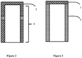
figures 2 et 3 représentent, de manière schématique, en coupe, deux modes de réalisation d'un doigt froid, - la
figure 4 représente en coupe, de manière schématique une variante de réalisation d'un dispositif de détection muni d'un cryostat. - La
figure 1 représente schématiquement un dispositif refroidisseur 1 et plus précisément un dispositif refroidisseur 1 connecté à un détecteur 2 pour former un dispositif de détection refroidi. - Le dispositif refroidisseur 1 comporte un système de refroidissement 3 et un doigt froid 4 terminé par une platine de refroidissement 5. L'élément à refroidir est disposé sur la platine de refroidissement 5 et est en contact avec la platine de refroidissement 5 de manière à être refroidi au moyen du système de refroidissement 3 et plus précisément au moyen d'un fluide de refroidissement qui circule à l'intérieur du doigt froid 4.
- Le dispositif refroidisseur comporte un doigt froid 4 qui assure la connexion mécanique et l'isolation thermique entre la platine de refroidissement 5 et le système de refroidissement 3. Dans l'exemple illustré, l'élément à refroidir est un détecteur.
- Le doigt froid 4 relie mécaniquement le système de refroidissement 3 avec la platine de refroidissement 5. Le système de refroidissement 3 fonctionne au moyen d'un fluide de refroidissement disposé à l'intérieur du doigt froid 4. Le fluide de refroidissement est à basse température de manière à refroidir le détecteur 2. De manière avantageuse, le système de refroidissement 3 est configuré pour que la température du fluide de refroidissement soit inférieure à -20°C, de préférence inférieure à 220K et de manière encore plus préférentielle inférieure à 150K.
- De manière générale, le système de refroidissement 3 utilise un fluide sous pression qui est confiné et qui circule à l'intérieur du doigt froid 4. Le fluide de refroidissement réalise le transfert thermique entre la platine de refroidissement 5 et le système de refroidissement 3. Le doigt froid 4 permet de canaliser le fluide de refroidissement entre la platine de refroidissement 5 et le système de refroidissement 3.
- Le doigt froid 4 est une pièce creuse de forme allongée. Préférentiellement, le doigt froid 4 est de forme cylindrique et de révolution. Une extrémité du doigt 4 est en contact thermique avec la platine de refroidissement 5 et l'autre extrémité est en contact mécanique avec le système de refroidissement 3 qui est à une température plus importante. Le doigt froid 4 a également une interface avec le système de refroidissement 3, par exemple un cryogénérateur.
- Il existe un gradient de température le long du doigt froid 4. Dans une variante de réalisation, l'extrémité du doigt froid 4 forme la platine de refroidissement 5. Le doigt froid 4 et la platine de refroidissement 5 sont avantageusement réalisés dans le même matériau ce qui facilite la tenue mécanique de ces deux éléments sur une plage de température importante. L'extrémité du doigt froid 4 en contact avec l'élément à refroidir fournit la puissance frigorifique créée par la détente du fluide de refroidissement.
- Comme indiqué précédemment, la platine 5 est connectée mécaniquement à son système de refroidissement 3 ce qui autorise des transferts de chaleur préjudiciables au bon refroidissement de l'élément présent sur la platine de refroidissement 5. Pour assurer un bon refroidissement, le doigt froid 4 est isolant thermiquement entre ses deux extrémités opposées de manière à minimiser les fuites thermiques qui existent entre la platine de refroidissement 5 et son système de refroidissement 3.
- L'embase du doigt froid 4 assure préférentiellement l'interface mécanique et l'étanchéité entre le doigt froid 1 et le système de refroidissement 3.
- Le système de refroidissement 3 peut être une machine à détente connue (communément nommé « Joule Thomson ») ou alors une machine cyclique connue, par exemple une machine utilisant le cycle de Stirling. Le système de refroidissement 3 peut comporter un oscillateur de pression qui génère une onde de pression dans un fluide et le fluide est successivement comprimé et détendu.
- Le système de refroidissement 3 comprend un oscillateur électromécanique qui génère, dans une enceinte active contenant un fluide, une onde de pression. Le fluide est avantageusement un gaz. L'enceinte comporte une partie munie d'un régénérateur mobile ou déplaceur qui utilise les cycles de détente et de compression du fluide pour réaliser un cycle de Stirling.
- L'enceinte est formée par l'intérieur du doigt froid 4 et la détente permet de refroidir une extrémité du doigt froid 4 (le haut du doigt froid sur les figures) et ainsi la platine de refroidissement. Le doigt froid 4 comporte au moins une paroi latérale définissant un canal de confinement du fluide de refroidissement depuis le système de refroidissement 3. Selon les modes de réalisation, la pression dans le doigt froid 4 peut être importante, par exemple entre 2 bar et 10 bar éventuellement jusqu'à 30 bar ou plus.
- Pour améliorer les performances du dispositif refroidisseur 1, il est intéressant de limiter les transferts de chaleur entre le système de refroidissement 3 et la platine de refroidissement 5. Il est particulièrement intéressant de placer un isolant thermique entre les deux extrémités opposées du doigt froid 4.
- Cette précaution permet de maintenir plus facilement l'isolation thermique entre la partie supérieure du doigt froid 4, par exemple à température cryogénique, et la partie inférieure du doigt froid qui est à une température supérieure, par exemple la température ambiante.
- Le doigt froid 4 comporte au moins une paroi latérale qui forme les côtés du doigt. Les côtés du doigt froid 4 peuvent être décomposés en une paroi latérale ou en plusieurs parois latérales. Le doigt froid 4 est terminé par la platine de refroidissement 5 qui vient fermer le doigt froid 4.
- Les parois latérales du doigt froid 4 comportent au moins une partie formée par un alliage métallique au moins partiellement amorphe, c'est-à-dire un matériau métallique non cristallin qui présente une structure atomique désordonnée. Par alliage métallique au moins partiellement amorphe, on entend un matériau comprenant au moins 50 % volumique de matériau amorphe, le reste du matériau étant à l'état polycristallin. Il est avantageux que le matériau contienne au moins 50% volumique de phase amorphe car cela permet de réaliser un matériau moins fragile. De manière particulièrement avantageuse, le matériau comprend au moins 90% volumique de phase amorphe de manière à avoir un matériau avec les performances mécaniques et thermiques optimales. Ce choix particulier permet une nette amélioration des performances en comparaison des doigts froids en alliages métalliques poly-cristallins de l'art antérieur. L'amélioration du caractère isolant du doigt froid est obtenue en utilisant un matériau qui présente une conductibilité thermique plus faible que l'alliage de TA6V utilisé dans l'art antérieur.
- Par conductivité thermique ou conductibilité thermique on entend la grandeur physique caractérisant le comportement des matériaux lors du transfert thermique par conduction. Par abus de langage, le terme de résistivité thermique pourra être utilisé pour caractériser la grandeur physique traduisant le comportement des matériaux s'opposant au transfert thermique par conduction. Cependant, cette formulation est à dissocier de la notion de résistance thermique utilisée couramment par les métallurgistes travaillant dans le domaine des alliages métalliques amorphes et traduisant l'écart de température qui existe entre la température ambiante et la température de transition vitreuse. Cet écart de température correspond à la plage de température dans laquelle l'alliage métallique amorphe peut être utilisé. Un alliage métallique amorphe résistant est donc un alliage ayant une température de transition vitreuse élevée. Par exemple, le document
US 5,032,196 présente la résistance thermique comme la différence de température qui existe entre la température de fusion et la température de transition vitreuse. - Ainsi, au moins une paroi latérale est formée au moins partiellement par une zone en alliage métallique amorphe. De manière particulièrement avantageuse, l'alliage métallique amorphe est un alliage à base d'hafnium. L'alliage métallique amorphe forme l'isolant thermique qui empêche ou ralentit le transfert de chaleur depuis l'extrémité du doigt froid 4 connectée au système de refroidissement 3 vers l'extrémité connectée à la platine de refroidissement 5.
- Les inventeurs ont découvert qu'un alliage métallique amorphe à base d'hafnium est particulièrement intéressant pour former au moins une partie d'un doigt froid. En effet, cela permet de réduire notablement la conductibilité thermique par rapport aux alliages cristallins utilisés couramment pour former les doigts froids. Ces alliages permettent également de réduire notablement la conductibilité thermique par rapport aux autres alliages métalliques réalisés sous forme amorphe.
- Les alliages métalliques à base d'hafnium sont particulièrement intéressants car ils peuvent être obtenus sous forme amorphe à l'état « massif ». En effet, d'autres alliages peuvent être obtenus à l'état amorphe mais sous la forme d'une poudre ou d'un ruban ce qui rend particulièrement difficile voire impossible la réalisation d'un doigt froid. A titre d'exemple, le document
US 5,032,196 décrit plusieurs alliages métalliques à l'état amorphe qui sont obtenus sous la forme de poudres et/ou de rubans, mais pas à l'état massif. Un alliage amorphe à l'état massif est un alliage dont la plus petite dimension est supérieure à 1 mm avant traitement mécanique. - Par alliage à base d'hafnium, il faut comprendre un alliage comportant au moins 17,5% atomique d'hafnium. L'alliage peut contenir du zirconium en plus de l'hafnium. Il est particulièrement avantageux que l'alliage contienne au moins 2% atomique de zirconium afin de limiter la masse volumique de l'alliage. La teneur totale en zirconium et en hafnium est inférieure ou égale à 70% atomique.
- L'alliage à base d'hafnium est un alliage au moins ternaire de manière à faciliter la formation d'un alliage amorphe stable. L'alliage ternaire comporte avantageusement de l'hafnium et au moins deux éléments choisis parmi le zirconium, le cuivre, le titane et l'aluminium.
- Il est avantageux que l'alliage contienne du cuivre et/ou du nickel afin de faciliter l'obtention d'un alliage à l'état amorphe.
- De manière avantageuse, l'alliage à base d'hafnium est un alliage au moins quaternaire de manière à accroitre la stabilité thermique en comparaison d'un alliage ternaire et ainsi réaliser plus facilement un alliage métallique amorphe à l'état massif. L'alliage quaternaire comporte avantageusement de l'hafnium, du zirconium, du cuivre et/ou du nickel et/ou un élément choisi parmi le titane et l'aluminium.
- L'alliage peut être un alliage quaternaire, quinaire ou sénaire ou plus. Les constituants de l'alliage sont choisis parmi les éléments déjà cités ci-dessus. Il est cependant possible d'utiliser d'autres éléments.
- Dans le cas d'un alliage ternaire, il peut être avantageux d'utiliser un alliage choisi parmi : Hf62Ni25Al13, Hf60Ni25Al15, Hf58Ni25Al17, Hf55Ni25Al20, Hf53Ni25Al22, Hf50Ni25Al25.
- Dans le cas d'un alliage quaternaire, il peut être avantageux d'utiliser un alliage choisi parmi : Hf51Cu27,75Ni9,25Al12, Hf48Cu29,25Ni9,75Al13 et Hf47Cu29,25Ni9,75Al14.
- Dans le cas d'un alliage quinaire, il peut être avantageux d'utiliser un alliage choisi parmi : Hf49Ta2Cu27,75Ni9,25Al12, Hf46Nb2Cu29,25Ni9,75Al13, Hf45,5Cu27,8Ni9,3Ti5Al12,4 et Hf44,5Cu27Ni13,5Al10Ti5.
- Par alliage au moins ternaire, on entend que les au moins trois constituants de l'alliage représentent 95% des atomes de l'alliage. Le reste de l'alliage peut être formé par des impuretés et l'impact sur des performances de l'alliage sera faible. Cependant, les autres éléments constituant l'alliage ont chacun une teneur inférieure à 1% atomique.
- Il est également avantageux que lorsque le cuivre est utilisé, la teneur en cuivre de l'alliage est inférieure à 40% atomique car cela engendre des difficultés de connexion entre le doigt froid et le dispositif refroidisseur. Lorsque l'alliage contient du cuivre, il est particulièrement avantageux que la teneur totale en hafnium et éventuellement en zirconium soit supérieure ou égale à la teneur en cuivre et de préférence strictement supérieure à la teneur en cuivre de manière à réduire encore plus les difficultés de connexion entre le doigt froid et le dispositif refroidisseur.
- De manière avantageuse, la teneur totale en zirconium et en hafnium est supérieure ou égale à la teneur de tout autre élément contenu dans l'alliage.
- Un alliage à base d'hafnium tel que décrit précédemment et à l'état amorphe présente une conductibilité thermique qui est inférieure à 4,5 W/m/°C à 20°C ce qui représente un gain d'au moins 20% par rapport à un alliage de TA6V utilisé communément. Ce gain permet de considérer la zone du doigt froid comme un isolant thermique.
- De manière encore plus avantageuse, l'alliage métallique contient au moins 20% atomique d'hafnium et de préférence entre 20% et 30% atomique pour former un alliage ayant une conductibilité thermique égale ou sensiblement égale à 4,2 W/m/K à 20°C.
- Préférentiellement, l'alliage métallique contient au moins 30% atomique d'hafnium et de préférence entre 30% et 40% atomique pour former un alliage ayant une conductibilité thermique égale ou sensiblement égale à 4 W/m/K à 20°C.
- Dans un mode de réalisation particulièrement avantageux, l'alliage métallique contient au moins 40% atomique et encore plus avantageusement au moins 45% atomique d'hafnium et de préférence au moins 50% atomique d'hafnium ce qui permet de former un alliage ayant une conductibilité thermique inférieure à 3,95 W/m/K à 20°C.
- Par exemple, la substitution d'atomes de Zirconium par des atomes d'Hafnium permet de réduire la valeur de conductibilité thermique de l'alliage à l'état amorphe.
- La conductibilité thermique de l'alliage Hf17,5Zr35Cu17,9Ni14,6Al10Ti5 est moins élevée que celle de l'alliage Zr52,5Cu17,9Ni14,6Al10Ti5 d'au moins 5%. La conductibilité thermique de l'alliage Hf26,25Zr26,25Cu17,9Ni14,6Al10Ti5 est moins élevée que celle de l'alliage Zr52,5Cu17,9Ni14,6Al10Ti5 d'au moins 8%. La conductibilité thermique de l'alliage Hf35Zr17,5Cu17,9Ni14,6Al10Ti5 est moins élevée que celle de l'alliage Zr52,5Cu17,9Ni14,6Al10Ti5 d'au moins 13%. La conductibilité thermique de l'alliage Hf52,5Cu17,9Ni14,6Al10Ti5 est moins élevée que celle de l'alliage Zr52,5Cu17,9Ni14,6Al10Ti5 d'au moins 16%.
- Plusieurs documents décrivent l'obtention d'alliages métalliques à l'état amorphe et plus particulièrement d'alliages métalliques qui contiennent par exemple de l'hafnium, du cuivre, du nickel, du titane et de l'aluminium. Les documents
US 8,163,109 etUS 7,645,350 décrivent des alliages amorphes pour former des projectiles. Ces documents décrivent des alliages présentant une masse volumique supérieure à 7g/cm3 et plus particulièrement supérieure à 10,5g/cm3. Cette masse volumique élevée apparait préjudiciable pour la formation d'un doigt froid performant d'un dispositif refroidisseur en comparaison de la masse volumique de l'alliage TA6V qui est égale à 4,4g/cm3. Ces valeurs de masse volumique sont d'autant plus défavorables que le module de Young des alliages présentés est sensiblement identique à celui de l'alliage TA6V. - Les inventeurs ont cependant découvert que, malgré la forte augmentation de la masse volumique avec ce type d'alliage, la configuration du doigt froid qui est une pièce creuse et statique entraine une faible dégradation des performances du dispositif refroidisseur et notamment des performances optique d'un détecteur optique placé sur la platine de refroidissement. En d'autres termes, contre toute attente, les inventeurs ont découvert que l'augmentation de la masse volumique ne se traduit pas par une dégradation nette des performances en vibration du doigt froid liées notamment aux vibrations du système de refroidissement. En effet, dans l'utilisation d'un cryostat, il convient de prendre en considération les performances en vibration du doigt froid ou de l'ensemble supporté par le doigt froid et par exemple, la fréquence de résonnance du doigt froid. La fréquence de résonnance est proportionnelle à la racine carrée du rapport E/d avec E le Module de Young et d la densité apparente.
- Les inventeurs ont également découvert que les alliages à base d'hafnium sont stables chimiquement et mécaniquement ce qui permet de modifier légèrement la composition des exemples ci-dessus sans que les propriétés thermiques soient changées. Pour cette raison, la teneur en hafnium peut être changée légèrement sans que cela modifie fortement les valeurs de conductibilité thermique. Par exemple, les atomes d'hafnium peuvent être remplacés par des atomes de zirconium dans la limite de 2% atomique sans que cela ne modifie drastiquement les performances thermiques.
- Il est également possible d'utiliser d'autres compositions, par exemple :
- ((HfxZr1-x)52.5Cu17.9Ni14.6Al10Ti5)100-yMy avec x variant entre 0,1 et 1, y variant entre 0 et 3 et M choisi parmi Nb, Co, Ag, B, Si, C, Sn, Y Cr, Mn, Fe, Ga, Ge, Mo, Ta et W car ces éléments permettent d'obtenir au moins 90% volumique de phase amorphe. Pour obtenir une zone ayant au moins 90% volumique de phase amorphe, il est avantageux de choisir un élément parmi Nb, Y, Co, Fe, Ag, Si, Ge, Ge et Sn.
- (HfxZr1-x)57Cu20Ni8Al10Ti5 avec x variant entre 0,1 et 1,
- (Hf55-xCu30N15)100-yTixAly avec x égal à 0 ou 5 et y égal à 0 ou 10.
- Dans un mode de réalisation particulier, le dispositif refroidisseur 1 est un cryostat, par exemple avec un vase de Dewar qui contient l'élément à refroidir. L'intérieur du cryostat est généralement soumis au vide pour limiter les entrées de chaleur. Le cryostat comporte une pompe de manière à atteindre le niveau de vide recherché. Le cryostat définit un canal d'accès à la zone à refroidir pour le passage du doigt froid 4 hors de la zone sous vide.
- Le fluide utilisé par le système de refroidissement 3 de type Stirling est généralement de l'hélium ou de l'azote, sous une pression moyenne de plusieurs dizaines de bars. L'oscillateur peut être rotatif ou linéaire. Il est également possible d'utiliser un système de refroidissement 3 de type Joule-Thomson.
- Pour une bonne tenue dans le temps du dispositif refroidisseur 1, il est préférable que le doigt froid 4 soit étanche au fluide utilisé par le système de refroidissement 3 pour éviter d'augmenter la consommation du refroidisseur de manière rédhibitoire et/ou de dégrader le niveau de vide à l'intérieur du cryostat.
- Le sommet du doigt froid également appelé platine de refroidissement 5 est destiné à connecter thermiquement l'élément à refroidir au reste du doigt froid 1. De manière avantageuse, le sommet est réalisé en matériau cristallin, avantageusement en métal cristallin, afin d'obtenir une connexion thermique efficace avec l'élément à refroidir. En revanche, la partie supérieure de la paroi latérale est formée en métal amorphe pour réduire la conductibilité thermique dès la connexion avec l'élément à refroidir ou avec un élément intermédiaire. La platine de refroidissement 5 peut être réalisée dans un matériau rajouté sur les parois latérales ou dans une seule et même pièce avec la paroi latérale.
- Dans les modes de réalisation illustrés aux
figures 1 et4 , cette configuration permet d'avoir une partie sommitale présentant une bonne conduction thermique avec la platine de refroidissement 5 et une partie inférieure isolante thermiquement. - Comme illustré à la
figure 2 , de manière avantageuse, la zone en métal amorphe ou alliage métallique amorphe forme un anneau de manière à éviter la formation d'un canal de perte thermique entre l'élément à refroidir et une zone plus chaude. L'anneau en matériau amorphe sépare complètement le système de refroidissement 3 et la platine de refroidissement 5. Dans un mode de réalisation particulièrement avantageux illustré à lafigure 3 , la paroi latérale est complètement formée en alliage amorphe ce qui permet d'accroitre le caractère isolant thermique du doigt froid 4. - De manière avantageuse, le doigt froid 4 comporte également une embase 6 qui permet préférentiellement de faciliter la fixation au système de refroidissement 3. L'embase 6 peut être réalisée dans un métal amorphe identique ou différent de celui utilisé pour les parois latérales. Cependant, il est également possible d'utiliser un matériau cristallin pour former l'embase 6. Le matériau formant l'embase 6 est avantageusement réalisé dans un matériau compatible avec les assemblages à mettre en oeuvre, par exemple pour permettre une soudure laser, un brasage ou une soudure électrique.
- La fixation au système de refroidissement 3 peut être réalisée de différentes manières, par exemple par vissage, l'étanchéité étant assurée par des joints spécifiques.
- A titre d'exemple, les parois latérales d'un doigt froid 4 ont une hauteur comprise entre 20 et 40 mm et ont un diamètre extérieur égal à 6 mm et elles ont une épaisseur comprise entre 0,08 et 0,12mm. La hauteur minimale du doigt froid est au moins égale à 10mm.
- L'utilisation d'un métal amorphe permet de diminuer les pertes thermique en comparaison du même métal présenté sous sa forme monocristalline ou polycristalline. De cette manière, un doigt froid 4 formé au moins partiellement par du métal amorphe permet d'avoir une conductivité thermique réduite par rapport à un doigt froid 4 réalisé dans un matériau monocristallin ou polycristallin de composition identique ou proche. La diminution des pertes thermiques est au moins égale à 30% par rapport à un doigt froid 4 selon l'art antérieur.
- La structure amorphe du matériau permet de réduire le transport d'énergie par les phonons et les électrons ce qui a pour effet d'augmenter la résistance thermique du doigt froid 4. La partie en matériau amorphe permet de transformer le doigt froid en un isolant thermique.
- L'utilisation d'un matériau plus performant thermiquement permet par exemple de conserver une épaisseur de paroi latérale configurée pour assurer une bonne étanchéité du doigt froid, par exemple une bonne étanchéité du vide dans un cryostat.
- En comparaison d'un doigt froid 4 en alliage de titane de type Ta6V, l'alliage à base d'hafnium sous la forme d'un alliage métallique amorphe permet une meilleure isolation thermique entre l'extrémité chaude et l'extrémité froide tout en conservant de bonnes propriétés mécaniques. Les inventeurs ont observé que l'alliage à base d'hafnium en tant qu'alliage métallique amorphe est également plus performant que les autres alliages étudiés également sous forme de verres métalliques. Les valeurs de conductibilité thermique sont plus faibles au moins à l'état massif.
- Un tel dispositif de refroidissement 1 est particulièrement avantageux pour refroidir un détecteur infrarouge 2 fonctionnant à une température comprise entre 50K et 150K.
- Selon les modes de réalisation, les parois latérales sont formées par le même matériau avec des régions amorphes et des régions cristallines. De manière avantageuse, toute la hauteur des parois latérales est formée par le métal amorphe ce qui permet de réduire au maximum les pertes thermiques.
- Dans un mode de réalisation particulier, plusieurs matériaux différents sont utilisés pour former le doigt froid 4.
- La diminution des pertes thermiques par conduction solide à travers le doigt froid 4 permet de concevoir un dispositif refroidisseur 1 qui présente une consommation réduite de son système de refroidissement 3. Il est également possible de concevoir un dispositif refroidisseur 1 plus compact car les dimensions verticales du doigt froid 4 peuvent être réduites afin de conserver des pertes thermiques sensiblement identiques à ce qui existe pour un dispositif selon l'art antérieur.
- Les dispositifs de refroidissement 1 fonctionnant dans des atmosphères inertes ou contrôlées, les risques de corrosion sont limités voire nulles.
- Le doigt froid reliant mécaniquement le système de refroidissement à la platine de refroidissement, aucune caractéristique magnétique particulière n'est recherchée dans cette partie du dispositif.
- Comme indiqué plus haut, le dispositif refroidisseur 1 peut être utilisé dans un dispositif de détection. Le détecteur 2 ou dispositif de détection refroidi au moyen du doigt froid 1 comporte un circuit de détection 2a et un circuit de lecture 2b. Les circuits de lecture 2b et de détection 2a sont reliés électriquement de manière à ce que le circuit de lecture 2b traite l'information électrique émise par le circuit de détection 2a.
- Le circuit de lecture 2b est avantageusement formé dans un premier substrat semi-conducteur et le circuit de détection 2a est hybridé sur une première face principale du circuit de lecture 2b, c'est-à-dire connecté mécaniquement et électriquement sur le circuit de lecture 2b au moyen de billes métalliques.
- Le circuit de détection 2a comporte au moins un photodétecteur transformant un signal optique en un signal électrique. De manière préférentielle, le circuit de détection 2a comporte une pluralité de photodétecteurs. A titre d'exemple, le photodétecteur est une photodiode, un dispositif à puits quantiques ou à multipuits quantiques. Dans un mode de réalisation préférentiel, le photodétecteur réalise la détection dans le domaine de l'infrarouge. A titre d'exemple, le circuit de lecture 2b réalise la polarisation du circuit de détection 2a et la transformation d'un signal en courant émis par le photodétecteur en un signal en tension.
- Dans un mode de réalisation particulier qui peut être combiné aux précédents, le circuit de détection 2a est formé sur un premier substrat semi-conducteur et le circuit de lecture 2b est formé sur un second substrat semi-conducteur de manière à obtenir simultanément de bonnes caractéristiques de détection et de bonnes performances électriques du circuit de lecture 2b. Les deux substrats sont formés dans des matériaux différents. Avantageusement, l'un des deux substrats ou les deux substrats sont monocristallins. A titre d'exemple, le substrat du circuit de détection 2a est un matériau dit II-VI, par exemple à base de HgCdTe et le substrat du circuit de lecture 2b est un substrat à base de silicium. De manière avantageuse, les substrats en matériau II-VI sont refroidis afin de fournir des performances de détection accrues. Il est également possible d'utiliser un matériau dit III-V, par exemple à base de InSb ou InGaAs.
- Pour obtenir un système compact, les deux circuits sont avantageusement hybridés et ils forment le composant hybridé. L'hybridation des deux substrats est avantageusement réalisée par une ou plusieurs billes 7 en matériau électriquement conducteur qui sont disposées entre les deux circuits. Le circuit de détection 2a est hybridé sur une première face principale du circuit de lecture 2b de manière à former un ensemble monobloc et à faciliter la connexion électrique entre ces deux circuits. La première face principale du circuit de lecture 2b est avantageusement formée par une couche en matériau électriquement isolant qui recouvre le substrat semi-conducteur et à l'intérieur de laquelle sont disposées des lignes électriquement conductrices. La deuxième face principale du circuit de lecture 2b est par exemple la face arrière du substrat semi-conducteur.
- Un écran froid 8 (ou coldshield en anglais) est fixé sur le circuit de lecture 2b ou sur une table froide. L'écran froid 8 est fixé de manière à entourer le circuit de détection 2a présent sur la première face principale du circuit de lecture 2b. L'écran froid 8 peut comporter une lentille 8a.
- L'écran froid 8 est réalisé principalement dans un matériau opaque au rayonnement à détecter afin de former une zone opaque. L'écran froid 8 comporte une zone transparente au rayonnement à détecter, ce qui permet de définir la zone d'observation du circuit de détection 2a. L'axe optique X du circuit de détection 2a traverse la zone transparente. La zone transparente peut être formée par un trou ou par un dispositif optique, par exemple une ou plusieurs lentilles qui sont utilisées pour délimiter la zone d'observation du dispositif de détection. De cette manière, le rayonnement incident traverse l'écran froid 8 avant d'être capté par le circuit de détection 2a. Dans le mode de réalisation illustré, l'écran froid 8 est posé directement sur le circuit de lecture, mais il est également envisageable de poser l'écran froid 8 sur une table froide séparant le circuit de lecture et le doigt froid.
- Dans un mode de réalisation avantageux illustré à la
figure 4 , le dispositif de détection comporte un cryostat muni d'un vase Dewar 9 qui incorpore le détecteur 2. Le cryostat est mis sous vide pour limiter la formation de courants convectifs gazeux et conductifs qui perturbent le fonctionnement du détecteur 2. Le doigt froid 1 est introduit dans le cryostat de manière à se coupler thermiquement au détecteur 2. - Dans cette configuration, des efforts mécaniques supplémentaires sont appliqués au doigt froid 1. La partie interne du doigt froid 1 est soumise à une pression de plusieurs bars alors que la partie externe est placée sous vide, par exemple à une pression de l'ordre de 10-5mbar.
- De manière préférentielle, le volume interne du cryostat est à une pression sub-atmosphérique. Dans un mode de réalisation avantageux, le circuit de détection 2a est placé sous vide pour diminuer les échanges thermiques par convection de cette partie du dispositif. La partie externe du cryostat peut alors être en contact avec une zone chaude tandis que le doigt froid 4 sert pour le refroidissement du détecteur 2.
- Dans un mode de réalisation particulièrement avantageux, le circuit de lecture 2b comporte un ou plusieurs plots de connexion 10 qui sont situés à l'extérieur de la surface délimitée par l'écran froid 8. Ces plots de connexion 10 permettent la transmission de signaux électriques depuis le circuit de lecture 2b vers d'autres circuits du dispositif de détection, par exemple un circuit de traitement 11 qui est configuré pour traiter l'image envoyée par le circuit de lecture 2b et/ou qui est configuré pour modifier la trajectoire d'un objet mobile sur lequel se trouve le dispositif de détection.
- Le plot de connexion 8 est relié au reste du circuit de lecture 2b au moyen d'un fil électriquement conducteur qui circule à l'intérieur du circuit de lecture 2b. De cette manière, il est possible d'avoir une surface plane assurant une connexion mécanique importante entre l'écran froid 8 et le circuit de lecture 2b, une très bonne opacité au rayonnement parasite et une étanchéité accrue au rayonnement. Cette configuration est particulièrement avantageuse dans le cas où le circuit de détection 2a est dans une atmosphère contrôlée voire sous vide car la fiabilité du dispositif est accrue. La connexion électrique entre le circuit de lecture 2b et le circuit de traitement 11 est réalisée à l'extérieur de l'espace fermé au moyen de connecteurs. Les connecteurs partent du circuit de lecture 2b hors de la surface fermée définie par la connexion avec l'écran froid 8.
- Le circuit de détection 2a est destiné à être relié thermiquement à la source froide formée par le système de refroidissement 3 afin de travailler à une température réduite. Dans le mode de réalisation particulier illustré aux
figures 1 et4 , le dispositif comporte une table froide formant la platine de refroidissement sur laquelle le circuit de lecture 2b est fixé. La table froide agit comme un support mécanique pour le composant hybridé. De manière avantageuse, la table froide est reliée électriquement au circuit de lecture 2b et elle participe dans le transit des signaux électriques vers le circuit de traitement 11. La seconde face principale du circuit de lecture 2b peut être fixée directement à la table froide. - Dans cette configuration, il y a successivement, la table froide, le circuit de lecture 2b et le circuit de détection 2a. La table froide est destinée à être reliée thermiquement au système de refroidissement 3 et le froid est imposé au circuit de lecture 2b et au circuit de détection 2a par l'intermédiaire de la table froide. En d'autres termes, la table froide est destinée à réaliser la connexion thermique entre le circuit de détection 2a et le système de refroidissement 3.
- Lorsqu'un cryostat est utilisé, une connexion électrique additionnelle 12, traverse le cryostat pour relier le détecteur au circuit de traitement 11.
- En alternative, la platine de refroidissement 5 n'est pas configurée pour recevoir un élément à refroidir ou le dispositif refroidisseur comporte plusieurs platines de refroidissement 5 dont certaines ne sont pas utilisées pour refroidir un détecteur ou un autre dispositif. La platine de refroidissement 5 permet de fixer les impuretés présentes dans le cryostat afin de les piéger. L'atmosphère dans le cryostat est alors plus propre.
- Dans un mode de réalisation particulier, le doigt froid est relié à la masse électrique de manière à évacuer des charges parasites qui pourraient entrainées une dégradation du circuit de lecture et/ou du circuit de détection par exemple au moyen d'une décharge électrostatique.
Claims (15)
- Dispositif refroidisseur comportant :- une platine de refroidissement (5),- un système de refroidissement (3) muni d'un fluide de refroidissement,- un doigt froid (4) creux et fermé à une extrémité par la platine de refroidissement (5), le fluide de refroidissement étant localisé dans le doigt froid (4) pour refroidir la platine de refroidissement (5), le doigt froid (4) comportant au moins une paroi latérale définissant un canal de confinement du fluide de refroidissement depuis le système de refroidissement (3),dispositif caractérisé en ce que:- ladite au moins une paroi latérale est formée au moins partiellement par une zone en alliage métallique au moins partiellement amorphe,- la zone en alliage métallique au moins partiellement amorphe est formée par un alliage au moins ternaire contenant au moins 17,5% atomique d'hafnium et éventuellement du cuivre avec une teneur maximale égale à 40% atomique de cuivre de manière à former un isolant thermique.
- Dispositif refroidisseur selon la revendication 1 caractérisé en ce que l'alliage métallique contient au moins 20% atomique d'hafnium.
- Dispositif refroidisseur selon la revendication 2 caractérisé en ce que l'alliage métallique contient au moins 30% atomique d'hafnium.
- Dispositif refroidisseur selon la revendication 3 caractérisé en ce que l'alliage métallique contient au moins 40% atomique d'hafnium.
- Dispositif refroidisseur selon la revendication 4 caractérisé en ce que l'alliage métallique contient au moins 50% atomique d'hafnium.
- Dispositif refroidisseur selon l'une quelconque des revendications précédentes, caractérisé en ce que l'alliage métallique contient du zirconium et en ce que la teneur totale en hafnium et en zirconium est inférieure ou égale à 70% atomique.
- Dispositif refroidisseur selon l'une quelconque des revendications précédentes, caractérisé en ce que l'alliage métallique contient du zirconium et en ce que la teneur totale en hafnium et en zirconium est supérieure à la teneur en tout autre élément de l'alliage métallique.
- Dispositif refroidisseur selon l'une quelconque des revendications précédentes caractérisé en ce que l'alliage métallique contient du cuivre et en ce que la teneur en cuivre est inférieure à la teneur totale en hafnium et éventuellement en zirconium.
- Dispositif refroidisseur selon l'une quelconque des revendications précédentes caractérisé en ce que l'alliage métallique amorphe est choisi parmi les alliages de Hf52,5Cu17,9Ni14,6Al10Ti5, Hf35Zr17,5Cu17,9Ni14,6Al10Ti5, Hf17,5Zr35Cu17,9Ni14,6Al10Ti5 et Hf26,25Zr26,25Cu17,9Ni14,6Al10Ti5
- Dispositif refroidisseur selon l'une des quelconque des revendications 1 à 8 caractérisé en ce que l'alliage métallique amorphe est choisi parmi les alliages de ((HfxZr1-x)52.5Cu17.9Ni14.6Al10Ti5)100-yMy avec x variant entre 0,1 et 1, y variant entre 0 et 3 et M choisi parmi Nb, Co, Ag, B, Si, C, Sn, Y Cr, Mn, Fe, Ga, Ge, Mo, Ta et W, (HfxZr1-x)57Cu20Ni8Al10Ti5 avec x variant entre 0,1 et 1 et (Hf55-xCu30Ni15)100-yTixAly avec x égal à 0 ou 5 et y égal à 0 ou 10.
- Dispositif refroidisseur selon l'une des quelconque des revendications 1 à 8 caractérisé en ce que l'alliage métallique amorphe est choisi parmi les alliages Hf62Ni25Al13, Hf60Ni25Al15, Hf58Ni25Al17, Hf55Ni25Al20, Hf53Ni25Al22, Hf50Ni25Al25, Hf51Cu27,75Ni9,25Al12, Hf48Cu29,25Ni9,75Al13, Hf47Cu29,25Ni9,75Al14, Hf49Ta2Cu27,75Ni9,25Al12, Hf46Nb2Cu29,25Ni9,75Al13, Hf45,5Cu27,8Ni9,3Ti5Al12,4 et Hf44,5Cu27Ni13,5Al10Ti5.
- Dispositif refroidisseur selon l'une quelconque des revendications précédentes, caractérisé en ce que la zone en alliage métallique au moins partiellement amorphe forme un anneau séparant complètement le système de refroidissement et la platine de refroidissement.
- Dispositif refroidisseur selon l'une quelconque des revendications précédentes, caractérisé en ce que la au moins une paroi latérale est complètement formée par un alliage métallique au moins partiellement amorphe de manière à relier le système de refroidissement et la platine de refroidissement.
- Dispositif refroidisseur selon l'une quelconque des revendications précédentes, caractérisé en ce qu'un photodétecteur est connecté à la platine de refroidissement (5).
- Dispositif refroidisseur selon l'une quelconque des revendications précédentes, caractérisé en ce que le doigt froid (4) est sous atmosphère inerte.
Applications Claiming Priority (1)
| Application Number | Priority Date | Filing Date | Title |
|---|---|---|---|
| FR1650457A FR3046880B1 (fr) | 2016-01-20 | 2016-01-20 | Dispositif refroidisseur comportant un doigt froid ameliore. |
Publications (2)
| Publication Number | Publication Date |
|---|---|
| EP3196947A1 true EP3196947A1 (fr) | 2017-07-26 |
| EP3196947B1 EP3196947B1 (fr) | 2021-08-18 |
Family
ID=56069033
Family Applications (1)
| Application Number | Title | Priority Date | Filing Date |
|---|---|---|---|
| EP17151899.6A Active EP3196947B1 (fr) | 2016-01-20 | 2017-01-18 | Dispositif refroidisseur comportant un doigt froid ameliore |
Country Status (4)
| Country | Link |
|---|---|
| US (1) | US10168206B2 (fr) |
| EP (1) | EP3196947B1 (fr) |
| FR (1) | FR3046880B1 (fr) |
| IL (1) | IL250154B (fr) |
Families Citing this family (6)
| Publication number | Priority date | Publication date | Assignee | Title |
|---|---|---|---|---|
| US11079281B2 (en) * | 2019-01-17 | 2021-08-03 | Uvia Group Llc | Cold stage actuation of optical elements including an optical light shield and a lenslet array connected to a cold finger |
| US11002607B2 (en) * | 2019-04-01 | 2021-05-11 | Raytheon Company | Direct mounting of filters or other optical components to optical detectors using flexures |
| US12224714B1 (en) | 2020-05-15 | 2025-02-11 | AmpliTech, Inc. | Multiple transistor low noise amplifier optimized for cryogenic temperatures |
| US12212287B1 (en) * | 2020-05-15 | 2025-01-28 | AmpliTech, Inc. | Low noise amplifiers/front-ends optimized for use in 5G networks |
| US12231091B1 (en) | 2020-05-15 | 2025-02-18 | AmpliTech, Inc. | Multiple transistor LNA MMIC design |
| US12577878B2 (en) * | 2024-04-11 | 2026-03-17 | Pratt & Whitney Canada Corp. | Leading edge plating on low pressure compressor vane for weight and strength optimization |
Citations (4)
| Publication number | Priority date | Publication date | Assignee | Title |
|---|---|---|---|---|
| US5032196A (en) | 1989-11-17 | 1991-07-16 | Tsuyoshi Masumoto | Amorphous alloys having superior processability |
| US7645350B1 (en) | 2004-04-06 | 2010-01-12 | The United States Of America As Represented By The Secretary Of The Army | High-density metallic glass alloys |
| US8163109B1 (en) | 2004-04-06 | 2012-04-24 | The United States Of America As Represented By The Secretary Of The Army | High-density hafnium-based metallic glass alloys that include six or more elements |
| US20150021477A1 (en) | 2013-07-18 | 2015-01-22 | Société Française De Détecteurs Infrarouges - Sofradir | Detection device comprising an improved cold finger |
Family Cites Families (3)
| Publication number | Priority date | Publication date | Assignee | Title |
|---|---|---|---|---|
| US5198671A (en) * | 1991-06-17 | 1993-03-30 | Rockwell International Corporation | Apparatus for large area infrared focal plane |
| US8910486B2 (en) * | 2010-07-22 | 2014-12-16 | Flir Systems, Inc. | Expander for stirling engines and cryogenic coolers |
| KR101735571B1 (ko) * | 2010-08-20 | 2017-05-16 | 삼성전자주식회사 | 방열 재료, 상기 방열 재료로 만들어진 접합부를 포함하는 발광 다이오드 패키지 |
-
2016
- 2016-01-20 FR FR1650457A patent/FR3046880B1/fr not_active Expired - Fee Related
-
2017
- 2017-01-17 IL IL250154A patent/IL250154B/en active IP Right Grant
- 2017-01-18 EP EP17151899.6A patent/EP3196947B1/fr active Active
- 2017-01-23 US US15/412,389 patent/US10168206B2/en active Active
Patent Citations (4)
| Publication number | Priority date | Publication date | Assignee | Title |
|---|---|---|---|---|
| US5032196A (en) | 1989-11-17 | 1991-07-16 | Tsuyoshi Masumoto | Amorphous alloys having superior processability |
| US7645350B1 (en) | 2004-04-06 | 2010-01-12 | The United States Of America As Represented By The Secretary Of The Army | High-density metallic glass alloys |
| US8163109B1 (en) | 2004-04-06 | 2012-04-24 | The United States Of America As Represented By The Secretary Of The Army | High-density hafnium-based metallic glass alloys that include six or more elements |
| US20150021477A1 (en) | 2013-07-18 | 2015-01-22 | Société Française De Détecteurs Infrarouges - Sofradir | Detection device comprising an improved cold finger |
Non-Patent Citations (1)
| Title |
|---|
| ZHANG H ET AL: "Mechanical behavior of bulk (ZrHf)TiCuNiAl amorphous alloys", SCRIPTA MATERIALIA, ELSEVIER, AMSTERDAM, NL, vol. 49, no. 5, September 2003 (2003-09-01), pages 447 - 452, XP004431953, ISSN: 1359-6462, DOI: 10.1016/S1359-6462(03)00295-1 * |
Also Published As
| Publication number | Publication date |
|---|---|
| EP3196947B1 (fr) | 2021-08-18 |
| IL250154B (en) | 2021-06-30 |
| FR3046880A1 (fr) | 2017-07-21 |
| US10168206B2 (en) | 2019-01-01 |
| FR3046880B1 (fr) | 2018-02-23 |
| IL250154A0 (en) | 2017-03-30 |
| US20170205281A1 (en) | 2017-07-20 |
Similar Documents
| Publication | Publication Date | Title |
|---|---|---|
| EP3196947B1 (fr) | Dispositif refroidisseur comportant un doigt froid ameliore | |
| EP2827375B1 (fr) | Dispositif de détection comportant un doigt froid amélioré | |
| EP2335037B1 (fr) | Detecteur de rayonnement electromagnetique a microencapsulation et dispositif pour la detection de rayonnement electromagnetique mettant en oeuvre de tels detecteurs | |
| EP1243903B1 (fr) | Détecteurs de rayonnement et procédés pour les fabriquer | |
| CA2853751C (fr) | Detecteur infrarouge a base de micro-planches bolometriques suspendues | |
| EP3323023B1 (fr) | Cellule à gaz pour un capteur atomique et procédé de remplissage d'une cellule à gaz | |
| EP2466283A1 (fr) | Détecteur infrarouge à base de micro-planches bolométriques suspendues | |
| EP2652844B1 (fr) | Module a gain laser et methode de fabrication d'un tel module | |
| EP1518279B1 (fr) | Dispositif de maintien d un objet sous vide et procedes de f abrication de ce dispositif, application aux detecteurs infrarouges non refroidis | |
| FR3045148A1 (fr) | Dispositif de detection a membranes bolometriques suspendues a fort rendement d'absorption et rapport signal sur bruit | |
| FR3090830A1 (fr) | Dispositif de refroidissement comprenant une ceramique de grenat paramagnetique | |
| EP3563129B1 (fr) | Detecteur de rayonnement electromagnetique et notamment de rayonnement infrarouge et procede pour sa realisation | |
| FR2816447A1 (fr) | Dispositif de detection de rayonnements electromagnetiques tridimensionnel et procede de realisation de ce dispositif | |
| WO2021223951A1 (fr) | Procede de fabrication d'un microsysteme electromecanique et microsysteme electromecanique | |
| FR3064753B1 (fr) | Systeme de generation d’un champ magnetique vectoriel | |
| FR3030035A1 (fr) | Nanofil thermoelectrique a haute resolution et systeme detecteur couple par graphene | |
| FR3052245A1 (fr) | Dispositif cryogenique a echangeur compact | |
| EP0493208B1 (fr) | Doigt de refroidissement d'un circuit semi-conducteur et dispositif cryogénique pourvu d'un tel doigt | |
| EP4291862B1 (fr) | Système de détection de rayonnement électromagnétique et procédé de refroidissement | |
| US9952097B1 (en) | Infrared scene projector and conversion chip therefore | |
| FR2991812A1 (fr) | Dispositif de detection refroidi avec table froide amelioree | |
| Jasik et al. | Demonstration of thermoelectrically cooled MWIR InAs/GaSb focal plane arrays | |
| FR3156195A1 (fr) | Détecteur thermique comportant une membrane absorbante suspendue a isolation thermique améliorée | |
| EP0237801A1 (fr) | Laser comportant au moins un joint d'étanchéité | |
| CA2946474A1 (fr) | Projecteur de scene a infrarouge et puce de conversion associee |
Legal Events
| Date | Code | Title | Description |
|---|---|---|---|
| PUAI | Public reference made under article 153(3) epc to a published international application that has entered the european phase |
Free format text: ORIGINAL CODE: 0009012 |
|
| STAA | Information on the status of an ep patent application or granted ep patent |
Free format text: STATUS: THE APPLICATION HAS BEEN PUBLISHED |
|
| AK | Designated contracting states |
Kind code of ref document: A1 Designated state(s): AL AT BE BG CH CY CZ DE DK EE ES FI FR GB GR HR HU IE IS IT LI LT LU LV MC MK MT NL NO PL PT RO RS SE SI SK SM TR |
|
| AX | Request for extension of the european patent |
Extension state: BA ME |
|
| STAA | Information on the status of an ep patent application or granted ep patent |
Free format text: STATUS: REQUEST FOR EXAMINATION WAS MADE |
|
| 17P | Request for examination filed |
Effective date: 20180126 |
|
| RBV | Designated contracting states (corrected) |
Designated state(s): AL AT BE BG CH CY CZ DE DK EE ES FI FR GB GR HR HU IE IS IT LI LT LU LV MC MK MT NL NO PL PT RO RS SE SI SK SM TR |
|
| RAP1 | Party data changed (applicant data changed or rights of an application transferred) |
Owner name: LYNRED Owner name: UNIVERSITE GRENOBLE ALPES |
|
| RIC1 | Information provided on ipc code assigned before grant |
Ipc: G01J 1/02 20060101ALI20200910BHEP Ipc: G01J 5/06 20060101ALI20200910BHEP Ipc: F25D 19/00 20060101ALI20200910BHEP Ipc: C22C 30/02 20060101ALI20200910BHEP Ipc: G01J 5/04 20060101ALI20200910BHEP Ipc: H01L 31/103 20060101ALI20200910BHEP Ipc: C22C 45/10 20060101ALI20200910BHEP Ipc: H01L 31/024 20140101AFI20200910BHEP |
|
| GRAP | Despatch of communication of intention to grant a patent |
Free format text: ORIGINAL CODE: EPIDOSNIGR1 |
|
| STAA | Information on the status of an ep patent application or granted ep patent |
Free format text: STATUS: GRANT OF PATENT IS INTENDED |
|
| INTG | Intention to grant announced |
Effective date: 20201109 |
|
| GRAJ | Information related to disapproval of communication of intention to grant by the applicant or resumption of examination proceedings by the epo deleted |
Free format text: ORIGINAL CODE: EPIDOSDIGR1 |
|
| STAA | Information on the status of an ep patent application or granted ep patent |
Free format text: STATUS: REQUEST FOR EXAMINATION WAS MADE |
|
| GRAS | Grant fee paid |
Free format text: ORIGINAL CODE: EPIDOSNIGR3 |
|
| STAA | Information on the status of an ep patent application or granted ep patent |
Free format text: STATUS: GRANT OF PATENT IS INTENDED |
|
| GRAP | Despatch of communication of intention to grant a patent |
Free format text: ORIGINAL CODE: EPIDOSNIGR1 |
|
| INTC | Intention to grant announced (deleted) | ||
| RAP3 | Party data changed (applicant data changed or rights of an application transferred) |
Owner name: UNIVERSITE GRENOBLE ALPES Owner name: LYNRED |
|
| INTG | Intention to grant announced |
Effective date: 20210329 |
|
| GRAA | (expected) grant |
Free format text: ORIGINAL CODE: 0009210 |
|
| STAA | Information on the status of an ep patent application or granted ep patent |
Free format text: STATUS: THE PATENT HAS BEEN GRANTED |
|
| AK | Designated contracting states |
Kind code of ref document: B1 Designated state(s): AL AT BE BG CH CY CZ DE DK EE ES FI FR GB GR HR HU IE IS IT LI LT LU LV MC MK MT NL NO PL PT RO RS SE SI SK SM TR |
|
| REG | Reference to a national code |
Ref country code: GB Ref legal event code: FG4D Free format text: NOT ENGLISH |
|
| REG | Reference to a national code |
Ref country code: CH Ref legal event code: EP |
|
| REG | Reference to a national code |
Ref country code: DE Ref legal event code: R096 Ref document number: 602017044113 Country of ref document: DE |
|
| REG | Reference to a national code |
Ref country code: IE Ref legal event code: FG4D Free format text: LANGUAGE OF EP DOCUMENT: FRENCH Ref country code: AT Ref legal event code: REF Ref document number: 1422415 Country of ref document: AT Kind code of ref document: T Effective date: 20210915 |
|
| REG | Reference to a national code |
Ref country code: NL Ref legal event code: FP |
|
| REG | Reference to a national code |
Ref country code: LT Ref legal event code: MG9D |
|
| REG | Reference to a national code |
Ref country code: AT Ref legal event code: MK05 Ref document number: 1422415 Country of ref document: AT Kind code of ref document: T Effective date: 20210818 |
|
| PG25 | Lapsed in a contracting state [announced via postgrant information from national office to epo] |
Ref country code: ES Free format text: LAPSE BECAUSE OF FAILURE TO SUBMIT A TRANSLATION OF THE DESCRIPTION OR TO PAY THE FEE WITHIN THE PRESCRIBED TIME-LIMIT Effective date: 20210818 Ref country code: FI Free format text: LAPSE BECAUSE OF FAILURE TO SUBMIT A TRANSLATION OF THE DESCRIPTION OR TO PAY THE FEE WITHIN THE PRESCRIBED TIME-LIMIT Effective date: 20210818 Ref country code: HR Free format text: LAPSE BECAUSE OF FAILURE TO SUBMIT A TRANSLATION OF THE DESCRIPTION OR TO PAY THE FEE WITHIN THE PRESCRIBED TIME-LIMIT Effective date: 20210818 Ref country code: PT Free format text: LAPSE BECAUSE OF FAILURE TO SUBMIT A TRANSLATION OF THE DESCRIPTION OR TO PAY THE FEE WITHIN THE PRESCRIBED TIME-LIMIT Effective date: 20211220 Ref country code: NO Free format text: LAPSE BECAUSE OF FAILURE TO SUBMIT A TRANSLATION OF THE DESCRIPTION OR TO PAY THE FEE WITHIN THE PRESCRIBED TIME-LIMIT Effective date: 20211118 Ref country code: BG Free format text: LAPSE BECAUSE OF FAILURE TO SUBMIT A TRANSLATION OF THE DESCRIPTION OR TO PAY THE FEE WITHIN THE PRESCRIBED TIME-LIMIT Effective date: 20211118 Ref country code: AT Free format text: LAPSE BECAUSE OF FAILURE TO SUBMIT A TRANSLATION OF THE DESCRIPTION OR TO PAY THE FEE WITHIN THE PRESCRIBED TIME-LIMIT Effective date: 20210818 Ref country code: LT Free format text: LAPSE BECAUSE OF FAILURE TO SUBMIT A TRANSLATION OF THE DESCRIPTION OR TO PAY THE FEE WITHIN THE PRESCRIBED TIME-LIMIT Effective date: 20210818 Ref country code: RS Free format text: LAPSE BECAUSE OF FAILURE TO SUBMIT A TRANSLATION OF THE DESCRIPTION OR TO PAY THE FEE WITHIN THE PRESCRIBED TIME-LIMIT Effective date: 20210818 Ref country code: SE Free format text: LAPSE BECAUSE OF FAILURE TO SUBMIT A TRANSLATION OF THE DESCRIPTION OR TO PAY THE FEE WITHIN THE PRESCRIBED TIME-LIMIT Effective date: 20210818 |
|
| PG25 | Lapsed in a contracting state [announced via postgrant information from national office to epo] |
Ref country code: PL Free format text: LAPSE BECAUSE OF FAILURE TO SUBMIT A TRANSLATION OF THE DESCRIPTION OR TO PAY THE FEE WITHIN THE PRESCRIBED TIME-LIMIT Effective date: 20210818 Ref country code: LV Free format text: LAPSE BECAUSE OF FAILURE TO SUBMIT A TRANSLATION OF THE DESCRIPTION OR TO PAY THE FEE WITHIN THE PRESCRIBED TIME-LIMIT Effective date: 20210818 Ref country code: GR Free format text: LAPSE BECAUSE OF FAILURE TO SUBMIT A TRANSLATION OF THE DESCRIPTION OR TO PAY THE FEE WITHIN THE PRESCRIBED TIME-LIMIT Effective date: 20211119 |
|
| PG25 | Lapsed in a contracting state [announced via postgrant information from national office to epo] |
Ref country code: DK Free format text: LAPSE BECAUSE OF FAILURE TO SUBMIT A TRANSLATION OF THE DESCRIPTION OR TO PAY THE FEE WITHIN THE PRESCRIBED TIME-LIMIT Effective date: 20210818 |
|
| REG | Reference to a national code |
Ref country code: DE Ref legal event code: R097 Ref document number: 602017044113 Country of ref document: DE |
|
| PG25 | Lapsed in a contracting state [announced via postgrant information from national office to epo] |
Ref country code: SM Free format text: LAPSE BECAUSE OF FAILURE TO SUBMIT A TRANSLATION OF THE DESCRIPTION OR TO PAY THE FEE WITHIN THE PRESCRIBED TIME-LIMIT Effective date: 20210818 Ref country code: SK Free format text: LAPSE BECAUSE OF FAILURE TO SUBMIT A TRANSLATION OF THE DESCRIPTION OR TO PAY THE FEE WITHIN THE PRESCRIBED TIME-LIMIT Effective date: 20210818 Ref country code: RO Free format text: LAPSE BECAUSE OF FAILURE TO SUBMIT A TRANSLATION OF THE DESCRIPTION OR TO PAY THE FEE WITHIN THE PRESCRIBED TIME-LIMIT Effective date: 20210818 Ref country code: EE Free format text: LAPSE BECAUSE OF FAILURE TO SUBMIT A TRANSLATION OF THE DESCRIPTION OR TO PAY THE FEE WITHIN THE PRESCRIBED TIME-LIMIT Effective date: 20210818 Ref country code: CZ Free format text: LAPSE BECAUSE OF FAILURE TO SUBMIT A TRANSLATION OF THE DESCRIPTION OR TO PAY THE FEE WITHIN THE PRESCRIBED TIME-LIMIT Effective date: 20210818 Ref country code: AL Free format text: LAPSE BECAUSE OF FAILURE TO SUBMIT A TRANSLATION OF THE DESCRIPTION OR TO PAY THE FEE WITHIN THE PRESCRIBED TIME-LIMIT Effective date: 20210818 |
|
| PLBE | No opposition filed within time limit |
Free format text: ORIGINAL CODE: 0009261 |
|
| STAA | Information on the status of an ep patent application or granted ep patent |
Free format text: STATUS: NO OPPOSITION FILED WITHIN TIME LIMIT |
|
| 26N | No opposition filed |
Effective date: 20220519 |
|
| PG25 | Lapsed in a contracting state [announced via postgrant information from national office to epo] |
Ref country code: IT Free format text: LAPSE BECAUSE OF FAILURE TO SUBMIT A TRANSLATION OF THE DESCRIPTION OR TO PAY THE FEE WITHIN THE PRESCRIBED TIME-LIMIT Effective date: 20210818 |
|
| PG25 | Lapsed in a contracting state [announced via postgrant information from national office to epo] |
Ref country code: SI Free format text: LAPSE BECAUSE OF FAILURE TO SUBMIT A TRANSLATION OF THE DESCRIPTION OR TO PAY THE FEE WITHIN THE PRESCRIBED TIME-LIMIT Effective date: 20210818 Ref country code: MC Free format text: LAPSE BECAUSE OF FAILURE TO SUBMIT A TRANSLATION OF THE DESCRIPTION OR TO PAY THE FEE WITHIN THE PRESCRIBED TIME-LIMIT Effective date: 20210818 |
|
| REG | Reference to a national code |
Ref country code: CH Ref legal event code: PL |
|
| REG | Reference to a national code |
Ref country code: BE Ref legal event code: MM Effective date: 20220131 |
|
| PG25 | Lapsed in a contracting state [announced via postgrant information from national office to epo] |
Ref country code: LU Free format text: LAPSE BECAUSE OF NON-PAYMENT OF DUE FEES Effective date: 20220118 |
|
| PG25 | Lapsed in a contracting state [announced via postgrant information from national office to epo] |
Ref country code: BE Free format text: LAPSE BECAUSE OF NON-PAYMENT OF DUE FEES Effective date: 20220131 |
|
| PG25 | Lapsed in a contracting state [announced via postgrant information from national office to epo] |
Ref country code: LI Free format text: LAPSE BECAUSE OF NON-PAYMENT OF DUE FEES Effective date: 20220131 Ref country code: CH Free format text: LAPSE BECAUSE OF NON-PAYMENT OF DUE FEES Effective date: 20220131 |
|
| PG25 | Lapsed in a contracting state [announced via postgrant information from national office to epo] |
Ref country code: IE Free format text: LAPSE BECAUSE OF NON-PAYMENT OF DUE FEES Effective date: 20220118 |
|
| PG25 | Lapsed in a contracting state [announced via postgrant information from national office to epo] |
Ref country code: HU Free format text: LAPSE BECAUSE OF FAILURE TO SUBMIT A TRANSLATION OF THE DESCRIPTION OR TO PAY THE FEE WITHIN THE PRESCRIBED TIME-LIMIT; INVALID AB INITIO Effective date: 20170118 |
|
| PG25 | Lapsed in a contracting state [announced via postgrant information from national office to epo] |
Ref country code: MK Free format text: LAPSE BECAUSE OF FAILURE TO SUBMIT A TRANSLATION OF THE DESCRIPTION OR TO PAY THE FEE WITHIN THE PRESCRIBED TIME-LIMIT Effective date: 20210818 Ref country code: CY Free format text: LAPSE BECAUSE OF FAILURE TO SUBMIT A TRANSLATION OF THE DESCRIPTION OR TO PAY THE FEE WITHIN THE PRESCRIBED TIME-LIMIT Effective date: 20210818 |
|
| PG25 | Lapsed in a contracting state [announced via postgrant information from national office to epo] |
Ref country code: MT Free format text: LAPSE BECAUSE OF FAILURE TO SUBMIT A TRANSLATION OF THE DESCRIPTION OR TO PAY THE FEE WITHIN THE PRESCRIBED TIME-LIMIT Effective date: 20210818 |
|
| REG | Reference to a national code |
Ref country code: DE Ref legal event code: R079 Ref document number: 602017044113 Country of ref document: DE Free format text: PREVIOUS MAIN CLASS: H01L0031024000 Ipc: H10F0077600000 |
|
| PG25 | Lapsed in a contracting state [announced via postgrant information from national office to epo] |
Ref country code: TR Free format text: LAPSE BECAUSE OF FAILURE TO SUBMIT A TRANSLATION OF THE DESCRIPTION OR TO PAY THE FEE WITHIN THE PRESCRIBED TIME-LIMIT Effective date: 20210818 |
|
| PGFP | Annual fee paid to national office [announced via postgrant information from national office to epo] |
Ref country code: NL Payment date: 20260127 Year of fee payment: 10 |
|
| PGFP | Annual fee paid to national office [announced via postgrant information from national office to epo] |
Ref country code: GB Payment date: 20260128 Year of fee payment: 10 |
|
| PGFP | Annual fee paid to national office [announced via postgrant information from national office to epo] |
Ref country code: DE Payment date: 20260127 Year of fee payment: 10 |
|
| PGFP | Annual fee paid to national office [announced via postgrant information from national office to epo] |
Ref country code: FR Payment date: 20260128 Year of fee payment: 10 |