EP3196786A1 - Design assistance device, design assistance method, and program - Google Patents
Design assistance device, design assistance method, and program Download PDFInfo
- Publication number
- EP3196786A1 EP3196786A1 EP15841950.7A EP15841950A EP3196786A1 EP 3196786 A1 EP3196786 A1 EP 3196786A1 EP 15841950 A EP15841950 A EP 15841950A EP 3196786 A1 EP3196786 A1 EP 3196786A1
- Authority
- EP
- European Patent Office
- Prior art keywords
- curved shape
- models
- shape model
- product
- shape models
- Prior art date
- Legal status (The legal status is an assumption and is not a legal conclusion. Google has not performed a legal analysis and makes no representation as to the accuracy of the status listed.)
- Pending
Links
Images




Classifications
-
- G—PHYSICS
- G06—COMPUTING OR CALCULATING; COUNTING
- G06F—ELECTRIC DIGITAL DATA PROCESSING
- G06F30/00—Computer-aided design [CAD]
- G06F30/10—Geometric CAD
- G06F30/17—Mechanical parametric or variational design
-
- G—PHYSICS
- G06—COMPUTING OR CALCULATING; COUNTING
- G06F—ELECTRIC DIGITAL DATA PROCESSING
- G06F30/00—Computer-aided design [CAD]
- G06F30/20—Design optimisation, verification or simulation
-
- G—PHYSICS
- G06—COMPUTING OR CALCULATING; COUNTING
- G06F—ELECTRIC DIGITAL DATA PROCESSING
- G06F30/00—Computer-aided design [CAD]
- G06F30/20—Design optimisation, verification or simulation
- G06F30/23—Design optimisation, verification or simulation using finite element methods [FEM] or finite difference methods [FDM]
-
- G—PHYSICS
- G06—COMPUTING OR CALCULATING; COUNTING
- G06N—COMPUTING ARRANGEMENTS BASED ON SPECIFIC COMPUTATIONAL MODELS
- G06N5/00—Computing arrangements using knowledge-based models
- G06N5/04—Inference or reasoning models
-
- G—PHYSICS
- G06—COMPUTING OR CALCULATING; COUNTING
- G06F—ELECTRIC DIGITAL DATA PROCESSING
- G06F2113/00—Details relating to the application field
- G06F2113/26—Composites
Definitions
- the present invention relates to a design support apparatus, a design support method, and a program and is particularly suited for use in a design support apparatus, design support method, and program for supporting designing of a thick fiber material.
- the fiber-reinforced composite material is a composite material manufactured by combining fibers with a support material and has excellent material properties, that is, light weight and high strength as compared to single materials.
- Examples of the fiber-reinforced composite material include CMC (Ceramic Matrix Composites) and FRP (Fiber Reinforced Plastics). These CMC and FRP are used for aircraft elements and can enhance the strength and fuel efficiency.
- a 3-dimensional shape model of the product which is a final product, is firstly created by using design support tools such as 3-dimensional CAD (Computer Aided Design) software.
- design support tools such as 3-dimensional CAD (Computer Aided Design) software.
- a fiber material is manufactured by predicting a material shape before deformation processing on the basis of the created 3-dimensional shape model; and then the deformation processing of the fiber material is actually performed, thereby manufacturing the product.
- PTL 1 discloses a technology that easily and accurately predicts a surface shape of woven fabric after being woven based on an organizational chart of the woven fabric by using woven fabric CAD. Specifically speaking, PTL 1 discloses the technology used when weaving the woven fabric, to predict a force received by organizational points where the warp yarns intersect with the weft yarns, and directions and distance of movements of the organizational points by the received force, move the organizational points in the predicted directions by the predicted distance, and thereby display the surface structure of the completed woven fabric on a screen.
- the technology described in PTL 1 only predicts the shape of the woven fabric which is a flat surface even after it is woven on the basis of the planar organizational chart; and cannot predict changes in the shape of the thick woven fabric configured by placing many fiber layers on top of each other. Moreover, the technology described in PTL 1 predicts the shape after weaving (the shape of the product which is a final product) on the basis of the organizational chart before weaving (the material shape before the deformation processing), so that the technology described in PTL 1 cannot predict the material shape from the shape of the product.
- the technology described in PTL 1 cannot predict the material shape before the deformation processing from a 3-dimensional shape model of the product which uses the fiber-reinforced composite material.
- the product which uses the fiber-reinforced composite material is configured by placing many fiber layers on top of each other as mentioned above, it has a thick, complicated shape and has anisotropy, which means that the strength depends on fiber directions; and, in that regard, the product which uses the fiber-reinforced composite material is significantly different from normal woven fabric.
- the present invention was devised in consideration of the above-described circumstances and proposes a design support apparatus, design support method, and program capable of predicting, with good accuracy, the material shape before the deformation processing from the 3-dimensional shape model of the product which uses the fiber-reinforced composite material.
- a design support apparatus for supporting designing of a product which uses a fiber material
- the design support apparatus includes a processor that creates a predicted shape model by predicting a shape of the product before deformation processing, and wherein the processor: creates a 3-dimensional shape model of the product; creates curved shape models by separating the 3-dimensional shape model into two or more fiber layers; sets a correspondence relationship between the curved shape models; creates an orientation vector field in the curved shape models; and predicts the shape of the product before the deformation processing by developing the curved shape models on a flat surface on the basis of the correspondence relationship between the curved shape models and the orientation vector field in the curved shape models, and creates the predicted shape model on the basis of the predicted shape.
- a design support method for supporting designing of a product which uses a fiber material
- the design support method includes the following steps executed by a processor that creates a predicted shape model by predicting a shape of the product before deformation processing: a first step of creating a 3-dimensional shape model of the product; a second step of creating curved shape models by separating the 3-dimensional shape model into two or more fiber layers; a third step of setting a correspondence relationship between the curved shape models; a fourth step of creating an orientation vector field in the curved shape models; and a fifth step of predicting the shape of the product before the deformation processing by developing the curved shape models on a flat surface on the basis of the correspondence relationship between the curved shape models and the orientation vector field in the curved shape models, and creating the predicted shape model on the basis of the predicted shape.
- a program for supporting designing of a product which uses a fiber material wherein the program causes a computer to execute: a first step of creating a 3-dimensional shape model of the product; a second step of creating curved shape models by separating the 3-dimensional shape model into two or more fiber layers; a third step of setting a correspondence relationship between the curved shape models; a fourth step of creating an orientation vector field in the curved shape models; and a fifth step of predicting the shape of the product before the deformation processing by developing the curved shape models on a flat surface on the basis of the correspondence relationship between the curved shape models and the orientation vector field in the curved shape models, and creating the predicted shape model on the basis of the predicted shape.
- the material shape before the deformation processing can be predicted with good accuracy from the 3-dimensional shape model of the product which uses the fiber-reinforced composite material.
- Fig. 1 illustrates an overall configuration of a design support apparatus 1 according to this embodiment.
- the design support apparatus 1 is a computer configured by including a processor 11, an input unit 12, a CAD (Computer Aided Design) data storage unit 13, a display unit 14, and a memory 15.
- the processor 11 includes a CPU (Central Processing Unit), a RAM (Random Access Memory), and so on and controls the operation of the design support apparatus 1 in a supervising manner in cooperation with various programs stored in the CAD data storage unit 13 or the memory 15.
- CPU Central Processing Unit
- RAM Random Access Memory
- the input unit 12 is an interface for accepting inputs from a user and is, for example, a keyboard and a mouse.
- the CAD data storage unit 13 is a storage medium that stores a design support tool containing CAD-related application programs and data and stores CAD data created by using this design support tool.
- the display unit 14 is a display device such as an LCD (Liquid Crystal Display) that displays a shape model based on CAD data.
- the display unit 14 displays a 3-dimensional shape model MDL1 of a product, which is a final product manufactured by using a fiber-reinforced composite material, on a display screen.
- the display unit 14 displays a predicted shape model MDL2, which is predicted when this 3-dimensional shape model MDL1 is developed on a flat surface, on the display screen.
- the 3-dimensional shape model MDL1 is a 3-dimensional shape model of a product, which is a final product manufactured by using the fiber-reinforced composite material as mentioned above, and is created by cooperation between the processor 11 and the design support tool in advance.
- This 3-dimensional shape model MDL1 is, for example, CMC (Ceramic Matrix Composites) and has a curved surface portion in this embodiment. Moreover, this 3-dimensional shape model MDL1 is woven fabric configured by placing many fiber layers, which are formed by interlacing warp yarns with weft yarns, and has a thick shape as thick as the layers placed on top of each other. Regarding fiber directions of the warp yarns and the weft yarns, ideal fiber directions designated by the user via the input unit 12 are set.
- the fiber-reinforced composite material is characterized by anisotropy indicating that the strength depends on the fiber directions as compared to other composite materials. Therefore, the 3-dimensional shape model MDL1 having desired strength is created by setting ideal fiber directions of the warp yarns and the weft yarns in the 3-dimensional shape model MDL1.
- the predicted shape model MDL2 is a 3-dimensional shape model formed when the 3-dimensional shape model MDL1 is developed on the flat surface; and is created by cooperation between the processor 11, the design support tool, and a shape prediction unit 151 described later.
- This predicted shape model MDL2 is a shape model of a fiber material before deformation processing of the product which is the final product.
- the predicted shape model MDL2 is thick as a result of placing many fiber layers on top of each other and the fiber directions are set to its warp yarns and weft yarns in the same manner as the 3-dimensional shape model MDL1.
- the predicted shape model MDL2 can be created from the 3-dimensional shape model MDL1.
- the fiber material before the deformation processing is firstly manufactured in a manufacturing process. When this happens, reference is made to the predicted shape model MDL2 and, therefore, the fiber material can be manufactured with good accuracy. Then, the product with no discrepancy with the 3-dimensional shape model MDL1 can be manufactured by performing the deformation processing of this fiber material.
- the memory 15 is a storage medium that stores programs for executing processing for predicting the material shape in cooperation with the processor 11. Specifically speaking, there is a shape prediction unit 151 that predicts the predicted shape model MDL2 from the 3-dimensional shape model MDL1 by deforming the 3-dimensional shape model MDL1. Predicted shape model creation processing ( Fig. 3 ) executed by this shape prediction unit 151 will be explained later.
- Fig. 2 illustrates the outlines of manufacturing procedure in this embodiment.
- the manufacturing procedure is mainly composed of a design process and a manufacturing process.
- the 3-dimensional shape model MDL1 is created (SP1).
- the predicted shape model MDL2 is formed by predicting the shape formed when the created 3-dimensional shape model MDL1 is deformed to be developed on the flat surface (SP2).
- a fiber material MDL3 before the deformation processing is manufactured by referring to the predicted shape model MDL2 (SP3).
- a product MDL4 is manufactured by actually performing the deformation processing of this fiber material MDL3 (SP4).
- the manufactured product MDL4 is compared with the 3-dimensional shape model MDL1 and they are evaluated so as to improve the manufacturing procedure to be conducted next time or later.
- the 3-dimensional shape model MDL1 is created (SP1) and then the fiber material MDL3 is manufactured by predicting the shape of the fiber material from the 3-dimensional shape model MDL1 without creating the predicted shape model MDL2 (SP3). Then, the product MDL4 is manufactured by actually performing the deformation processing of the fiber material MDL3 (SP4).
- the fiber material MDL3 is ambiguously predicted and manufactured on the basis of the experts' skills and know-how by referring to the 3-dimensional shape model MDL1, so that discrepancies in the shape or the strength may sometimes occur between the product MDL4, which is the final product, and the 3-dimensional shape model MDL1.
- the resulting problem is that many defective products may be produced, thereby causing an increase in manufacturing costs.
- the fiber material MDL3 is manufactured with good accuracy by accurately predicting the shape to be formed by developing the 3-dimensional shape model MDL1 on the flat surface, and creating the predicted shape model MDL2 and the occurrence of discrepancies between the product MDL4, which is the final product, and the 3-dimensional shape model MDL1 is prevented.
- Fig. 3 illustrates the outlines of predicted shape model creation processing.
- the predicted shape model creation processing is processing executed for: predicting the shape to be formed when the 3-dimensional shape model MDL1 is deformed to be developed on the flat surface; and creating the predicted shape model MDL2 as mentioned above.
- the predicted shape model MDL2 is of a plate shape which has a constant thickness.
- the 3-dimensional shape model MDL1 is created (SP1). Then, a thickness portion of the created 3-dimensional shape model MDL1 is removed and the 3-dimensional shape model MDL1 is separated into two layers, that is, its upper surface and its lower surface, thereby creating curved shape models MDL11 (SP11). Meanwhile, regarding fiber directions of warp yarns and weft yarns of the curved shape models MDL11, the fiber directions which the user considers to be ideal are set (SP12).
- the 3-dimensional shape model MDL1 is developed on the flat surface while maintaining the correspondence relationship between the two layers of the curved shape models MDL11 created in step SP11 and maintaining the fiber directions set in step SP12 (SP13), and the predicted shape model MDL2 is created (SP2).
- Fig. 4 illustrates a detailed processing sequence for the predicted shape model creation processing.
- This predicted shape model creation processing is executed by cooperation between the processor 11, the design support tool, and the shape prediction unit 151 as triggered by the reception of an execution instruction, which has been issued by the user, by the input unit 12.
- the explanation will be given by referring to the processor 11 as a processing subject.
- the processor 11 firstly creates the 3-dimensional shape model MDL1 (SP1). Next, the processor 11 separates the created 3-dimensional shape model MDL1 into two layers, that is, its upper surface and its lower surface and creates the curved shape models MDL11 (SP11). Then, the processor 11 generates meshes on the surfaces of these two layers of the curved shape models MDL11 by using a plurality of triangles (SP111).
- the processor 11 associates the two layers of the curved shape models MDL11 by using vertexes and edges of the triangles formed on the surfaces by means of the mesh generation (SP112). The details of this processing for associating the two layers with each other will be explained later ( Fig. 5 ).
- the processor 11 sets orientation vectors, which are indicative of the fiber directions of the warp yarns and the weft yarns, to all the triangles formed on the surfaces by means of the mesh generation, thereby generating an orientation vector field (SP12).
- orientation vector field SP12
- the processor 11 develops the two layers of the curved shape models MDL11 on the flat surface on the basis of the correspondence relationship between the two layers of the curved shape models MDL11 associated with each other in step SP112 and the orientation vector field generated in step SP12 (SP13).
- the details of this flat surface development processing will be explained later ( Fig. 7 ).
- the processor 11 creates the predicted shape model MDL2 on the basis of the two layers of the curved shape models MDL11, which have been developed on the flat surface (SP2), and then terminates this processing.
- the meshes are generated on the surfaces of the two layers of the curved shape models MDL11 by using a plurality of triangles, where the meshes of the respective two layers which are then formed are defined as M 1 , M 2 .
- the orientation vectors are set to all the triangles formed on the surfaces of the curved shape models MDL11 by means of the mesh generation, where the orientation vectors which are set to the edges (P j k , P j l ) of the triangles are defined as A j k, l , B j k, l .
- step SP13 the two layers of the curved shape models MDL11 are developed on the flat surface, where a map formed by mapping from the 3-dimensional coordinate system xyz onto the plane coordinate system uv is defined as ⁇ u(P J i ), v(P j i ) ⁇ .
- This map makes it possible to convert a coordinate system of the triangle vertexes P j i from the 3-dimensional coordinate system xyz to the plane coordinate system uv and obtain coordinate values of the triangle vertexes on the flat surface.
- These coordinate values represent a development diagram and the curved shape models MDL11 can be developed on the flat surface on the basis of the development diagram.
- Fig. 5 illustrates the details of the processing for associating two layers with each other ( Fig. 4 : SP112).
- the vertex P 1 i of a triangle in the mesh M 1 is associated with a point in the mesh M 2 at the closest linear distance from the above-mentioned vertex as a corresponding point ⁇ 2 (P 1 i ) of the vertex P 1 i .
- ⁇ 2 (P 1 i ) ⁇ ⁇ P 2 ⁇ + ⁇ ⁇ P 2 ⁇ by using an internal ratio.
- Fig. 6 illustrates the details of the orientation vector field generation processing ( Fig. 4 : SP12).
- the processor 11 sets orientation vectors A j k, l , B j k, l to the triangles in the border region (SP121).
- the processor 11 equalizes each of the set orientation vectors A j k, l , B j k, l and makes the equalized orientation vectors propagate to all other triangles by simulating the state of heat transfer (SP122). As a result, an orientation vector field is generated (SP123).
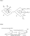
- Fig. 7 is a conceptual diagram of the flat surface development processing ( Fig. 4 : SP13).
- the curved shape models MDL11 are developed so that a gradient direction of the orientation vectors A j k, l , B j k, l which are set to edges (P j k , P j l ) of the triangles in the mesh M j matches a gradient direction of orientation vectors U j k, l , V j k, l which are set to edges ⁇ u(P j k, l ), v(P j k, l ) ⁇ when the edges (P j k , P j l ) are mapped to the plane coordinate system uv.
- a minimization function F 2 based on Expression 1 mentioned earlier is set as Expression 5 mentioned below and a minimization function F 3 based on Expression 2 mentioned earlier is set as Expression 6 mentioned below.
- the minimization function F 3 in Expression 6 below is a minimization function based on the constraint condition for points in the border
- Expression 2 mentioned earlier is multiplied by the Lagrange multipliers method and the minimization function based on the strong-form constraint condition is thereby obtained in order to guarantee that the borders of the meshes M 1 , M 2 correspond with each other.
- a minimization function F which integrates Expression 4 to Expression 6 is indicated as Expression 7 below. [Math.
- F 2 ⁇ P i j ⁇ M 1 / ⁇ M 1 u P i 1 ⁇ u ⁇ 2 P i 1 2 [Math. 6]
- F 3 ⁇ P i j ⁇ ⁇ M 1 ⁇ m u P i 1 ⁇ u ⁇ 2 P i 1 [Math. 7]
- F F 1 , u + F 1 , v + F 2 + F 3
- the curved shape models MDL11 can be developed on the flat surface to minimize the sum of strains by minimizing Expression 7 mentioned above by using the conjugate gradient method.
- a plane coordinate value to be found is a relative value
- a solution is calculated by fixing a coordinate value of an arbitrary one point.
- Fig. 8 illustrates development results obtained when the 3-dimensional shape model MDL1 is developed on the flat surface.
- the 3-dimensional shape model MDL1 is separated into two layers, while the fiber directions are set; and as the correspondence relationship between the two layers and the fiber directions are maintained, the two layers are developed on the flat surface, thereby creating the predicted shape model MDL2.
- the number of vertexes was 2000 and calculation time was 5 seconds. According to this result, the user can use the processing for creating the predicted shape model MDL2 without stress at actual designing sites.
- the product MDL4 which is the final product can be manufactured with good accuracy by manufacturing the fiber material MDL3 with reference to the predicted shape model MDL2 with such protrusions and dents.
- Fig. 9 illustrates the results of inverse mapping of coordinate lines of the upper surface and the lower surface in the plane coordinate system uv onto the 3-dimensional coordinate system xyz.
- a quadrangle formed by the coordinate lines which intersect with each other becomes closer to a square, this indicates less expansion and distortion.
- Flattened quadrangles are formed at a rising portion; and since this rising portion is actually the portion with much expansion and distortion, it is shown that the inverse mapping is calculated accurately.
- Fig. 10 illustrates expansion evaluation results via color maps.
- a xyz represents the sum of the areas of a set of triangles which include, as their vertex, a vertex of one triangle of focus in the 3-dimensional coordinate system xyz and, on the other hand, A uv represents the sum of the area of corresponding triangles in the plane coordinate system uv, the square root of their area ratio is calculated, thereby obtaining an expansion evaluation value A.
- the expansion evaluation value A When the expansion evaluation value A is 1, it means no expansion or contraction; and when the expansion evaluation value A is less than 1, it means contraction. Furthermore, when the expansion evaluation value A is more than 1, it means expansion. Since the evaluation value A of the rising portion of the upper surface is less than 1 and the rising portion of the actual product MDL4 is shrunk, it shows that the evaluation is accurate. Furthermore, since the evaluation value A of the rising portion of the lower surface is more than 1 and the rising portion of the actual product MDL4 is expanded, it shows that the evaluation is accurate.
- Fig. 11 shows the expansion evaluation results via a histogram. It shows that there are peaks at a portion where the expansion evaluation value A is less than 1, and at a portion where the expansion evaluation value A is more than 1, respectively.
- the expansion evaluation results via the color maps of Fig. 10 there is a portion of the upper surface where the evaluation value A is less than 1, and there is a portion of the lower surface where the evaluation value A is more than 1, so that consistency with the color maps can be confirmed.
- Quantitative evaluations were successively obtained with respect to surface-direction expansion and contraction by referring to the expansion evaluation results in Fig. 10 and Fig. 11 .
- the 3-dimensional shape model MDL1 is separated into two layers, that is, its upper surface and its lower surface and the 3-dimensional shape model MDL1 is developed on the flat surface on the basis of the correspondence relationship between the separated curved shape models MDL11 and the orientation vectors field, so that it is possible to reduce the calculation time and create the predicted shape model MDL2 at high speed as compared to the case where the 3-dimensional shape model MDL1 is directly developed on the flat surface.
- the fiber material MDL3 is manufactured by referring to the predicted shape model MDL2 and the product MDL4 is manufactured by performing the deformation processing of the fiber material MDL3; and it is thereby possible to prevent the occurrence of discrepancies in the shape and the strength between the product MDL4 and the 3-dimensional shape model MDL1. Since the product MDL4 similar to the ideal 3-dimensional shape model MDL1 can be manufactured, it is possible to curb the manufacturing cost.
- the 3-dimensional shape model MDL1 is separated into two layers to create the curved shape models MDL11; however, the invention is not limited to this example and, for example, the 3-dimensional shape model MDL1 may be separated into a plurality of layers such as three layers or more.
- the predicted shape model MDL2 can be created by developing the 3-dimensional shape model MDL1 on the flat surface by avoiding disrupting the correspondence relationship between the curved shape models MDL11 which are the plurality of layers. Since the predicted shape model MDL2 can be created in consideration of internal deformations of the 3-dimensional shape model MDL1, the accuracy of the predicted shape model MDL2 can be enhanced.
- deformations of the internal state which occur when the deformation processing of the fiber material MDL3 is performed may be recorded in a database in advance; and when the curved shape models MDL11 which are the two separated layers are developed on the flat surface, supervised search may be applied to this database.
- the predicted shape model MDL2 can be created in consideration of the internal deformations of the 3-dimensional shape model MDL1.
Landscapes
- Engineering & Computer Science (AREA)
- Physics & Mathematics (AREA)
- Theoretical Computer Science (AREA)
- Geometry (AREA)
- General Physics & Mathematics (AREA)
- Evolutionary Computation (AREA)
- General Engineering & Computer Science (AREA)
- Computer Hardware Design (AREA)
- Mathematical Optimization (AREA)
- Computational Mathematics (AREA)
- Mathematical Analysis (AREA)
- Pure & Applied Mathematics (AREA)
- Mathematical Physics (AREA)
- Software Systems (AREA)
- Computing Systems (AREA)
- Data Mining & Analysis (AREA)
- Computational Linguistics (AREA)
- Artificial Intelligence (AREA)
- Moulding By Coating Moulds (AREA)
- Processing Or Creating Images (AREA)
Abstract
Description
- The present invention relates to a design support apparatus, a design support method, and a program and is particularly suited for use in a design support apparatus, design support method, and program for supporting designing of a thick fiber material.
- In recent years, development of a fiber-reinforced composite material has been being promoted. The fiber-reinforced composite material is a composite material manufactured by combining fibers with a support material and has excellent material properties, that is, light weight and high strength as compared to single materials. Examples of the fiber-reinforced composite material include CMC (Ceramic Matrix Composites) and FRP (Fiber Reinforced Plastics). These CMC and FRP are used for aircraft elements and can enhance the strength and fuel efficiency.
- Regarding the procedure for manufacturing a product using the fiber-reinforced composite material, a 3-dimensional shape model of the product, which is a final product, is firstly created by using design support tools such as 3-dimensional CAD (Computer Aided Design) software. Next, a fiber material is manufactured by predicting a material shape before deformation processing on the basis of the created 3-dimensional shape model; and then the deformation processing of the fiber material is actually performed, thereby manufacturing the product.
- Meanwhile, products using the fiber-reinforced composite material has the drawback of high manufacturing cost. Therefore, it is necessary to improve both design technology and manufacturing technology in order to further promote the widespread use of the products which use the fiber-reinforced composite material. No reference will be herein made to the manufacturing technology, but the design technology will be explained. Particularly, an explanation will be given about the design technology for a product using a thick fiber-reinforced composite material configured by placing many fiber layers, which are formed by interlacing warp yarns with weft yarns, on top of each other.
-
PTL 1 discloses a technology that easily and accurately predicts a surface shape of woven fabric after being woven based on an organizational chart of the woven fabric by using woven fabric CAD. Specifically speaking,PTL 1 discloses the technology used when weaving the woven fabric, to predict a force received by organizational points where the warp yarns intersect with the weft yarns, and directions and distance of movements of the organizational points by the received force, move the organizational points in the predicted directions by the predicted distance, and thereby display the surface structure of the completed woven fabric on a screen. - PTL 1: Japanese Patent Application Laid-Open (Kokai) Publication No.
2004-292976 - However, the technology described in PTL 1: only predicts the shape of the woven fabric which is a flat surface even after it is woven on the basis of the planar organizational chart; and cannot predict changes in the shape of the thick woven fabric configured by placing many fiber layers on top of each other. Moreover, the technology described in
PTL 1 predicts the shape after weaving (the shape of the product which is a final product) on the basis of the organizational chart before weaving (the material shape before the deformation processing), so that the technology described inPTL 1 cannot predict the material shape from the shape of the product. - Specifically speaking, the technology described in
PTL 1 cannot predict the material shape before the deformation processing from a 3-dimensional shape model of the product which uses the fiber-reinforced composite material. Particularly, since the product which uses the fiber-reinforced composite material is configured by placing many fiber layers on top of each other as mentioned above, it has a thick, complicated shape and has anisotropy, which means that the strength depends on fiber directions; and, in that regard, the product which uses the fiber-reinforced composite material is significantly different from normal woven fabric. - So, it is generally difficult to predict the material shape before the deformation processing and the fiber directions before the deformation processing from the product which uses the fiber-reinforced composite material. Under the present circumstances, one has no choice but to depend on experts' skills and know-how in order to predict the material shape before the deformation processing from the 3-dimensional shape model of the product; and in this case, there is a problem of discrepancies in the shape and the strength between the actual product and the 3-dimensional shape model.
- The present invention was devised in consideration of the above-described circumstances and proposes a design support apparatus, design support method, and program capable of predicting, with good accuracy, the material shape before the deformation processing from the 3-dimensional shape model of the product which uses the fiber-reinforced composite material.
- In order to solve the above-described problem, provided according to the present invention is a design support apparatus for supporting designing of a product which uses a fiber material, wherein the design support apparatus includes a processor that creates a predicted shape model by predicting a shape of the product before deformation processing, and wherein the processor: creates a 3-dimensional shape model of the product; creates curved shape models by separating the 3-dimensional shape model into two or more fiber layers; sets a correspondence relationship between the curved shape models; creates an orientation vector field in the curved shape models; and predicts the shape of the product before the deformation processing by developing the curved shape models on a flat surface on the basis of the correspondence relationship between the curved shape models and the orientation vector field in the curved shape models, and creates the predicted shape model on the basis of the predicted shape.
- Furthermore, in order to solve the above-described problem, provided according to the present invention is a design support method for supporting designing of a product which uses a fiber material, wherein the design support method includes the following steps executed by a processor that creates a predicted shape model by predicting a shape of the product before deformation processing: a first step of creating a 3-dimensional shape model of the product; a second step of creating curved shape models by separating the 3-dimensional shape model into two or more fiber layers; a third step of setting a correspondence relationship between the curved shape models; a fourth step of creating an orientation vector field in the curved shape models; and a fifth step of predicting the shape of the product before the deformation processing by developing the curved shape models on a flat surface on the basis of the correspondence relationship between the curved shape models and the orientation vector field in the curved shape models, and creating the predicted shape model on the basis of the predicted shape.
- Furthermore, in order to solve the above-described problem, provided according to the present invention is a program for supporting designing of a product which uses a fiber material, wherein the program causes a computer to execute: a first step of creating a 3-dimensional shape model of the product; a second step of creating curved shape models by separating the 3-dimensional shape model into two or more fiber layers; a third step of setting a correspondence relationship between the curved shape models; a fourth step of creating an orientation vector field in the curved shape models; and a fifth step of predicting the shape of the product before the deformation processing by developing the curved shape models on a flat surface on the basis of the correspondence relationship between the curved shape models and the orientation vector field in the curved shape models, and creating the predicted shape model on the basis of the predicted shape.
- According to the present invention, the material shape before the deformation processing can be predicted with good accuracy from the 3-dimensional shape model of the product which uses the fiber-reinforced composite material.
-
- [
Fig. 1] Fig. 1 is an overall configuration diagram of a design support apparatus; - [
Fig. 2] Fig. 2 is an outline diagram of manufacturing procedure; - [
Fig. 3] Fig. 3 is an outline diagram of predicted shape model creation processing; - [
Fig. 4] Fig. 4 is a flowchart of the predicted shape model creation processing; - [
Fig. 5] Fig. 5 is a conceptual diagram of processing for associating two layers with each other; - [
Fig. 6] Fig. 6 is a conceptual diagram of orientation vector field generation processing; - [
Fig. 7] Fig. 7 is a conceptual diagram of flat surface development processing; - [
Fig. 8] Fig. 8 is a development result diagram; - [
Fig. 9] Fig. 9 is inverse mapping diagrams; - [
Fig. 10] Fig. 10 illustrates expansion evaluation results via color maps; - [
Fig. 11] Fig. 11 illustrates the expansion evaluation results via a histogram. - An embodiment of the present invention will be explained below in detail with respect to diagrams.
-
Fig. 1 illustrates an overall configuration of adesign support apparatus 1 according to this embodiment. Thedesign support apparatus 1 is a computer configured by including a processor 11, an input unit 12, a CAD (Computer Aided Design) data storage unit 13, a display unit 14, and a memory 15. The processor 11 includes a CPU (Central Processing Unit), a RAM (Random Access Memory), and so on and controls the operation of thedesign support apparatus 1 in a supervising manner in cooperation with various programs stored in the CAD data storage unit 13 or the memory 15. - The input unit 12 is an interface for accepting inputs from a user and is, for example, a keyboard and a mouse. The CAD data storage unit 13 is a storage medium that stores a design support tool containing CAD-related application programs and data and stores CAD data created by using this design support tool.
- The display unit 14 is a display device such as an LCD (Liquid Crystal Display) that displays a shape model based on CAD data. For example, the display unit 14 displays a 3-dimensional shape model MDL1 of a product, which is a final product manufactured by using a fiber-reinforced composite material, on a display screen. Moreover, the display unit 14 displays a predicted shape model MDL2, which is predicted when this 3-dimensional shape model MDL1 is developed on a flat surface, on the display screen.
- Now, the 3-dimensional shape model MDL1 and the predicted shape model MDL2 will be explained. The 3-dimensional shape model MDL1 is a 3-dimensional shape model of a product, which is a final product manufactured by using the fiber-reinforced composite material as mentioned above, and is created by cooperation between the processor 11 and the design support tool in advance.
- This 3-dimensional shape model MDL1 is, for example, CMC (Ceramic Matrix Composites) and has a curved surface portion in this embodiment. Moreover, this 3-dimensional shape model MDL1 is woven fabric configured by placing many fiber layers, which are formed by interlacing warp yarns with weft yarns, and has a thick shape as thick as the layers placed on top of each other. Regarding fiber directions of the warp yarns and the weft yarns, ideal fiber directions designated by the user via the input unit 12 are set.
- Incidentally, the fiber-reinforced composite material is characterized by anisotropy indicating that the strength depends on the fiber directions as compared to other composite materials. Therefore, the 3-dimensional shape model MDL1 having desired strength is created by setting ideal fiber directions of the warp yarns and the weft yarns in the 3-dimensional shape model MDL1.
- On the other hand, the predicted shape model MDL2: is a 3-dimensional shape model formed when the 3-dimensional shape model MDL1 is developed on the flat surface; and is created by cooperation between the processor 11, the design support tool, and a shape prediction unit 151 described later. This predicted shape model MDL2 is a shape model of a fiber material before deformation processing of the product which is the final product. The predicted shape model MDL2 is thick as a result of placing many fiber layers on top of each other and the fiber directions are set to its warp yarns and weft yarns in the same manner as the 3-dimensional shape model MDL1.
- According to this embodiment, the predicted shape model MDL2 can be created from the 3-dimensional shape model MDL1. The fiber material before the deformation processing is firstly manufactured in a manufacturing process. When this happens, reference is made to the predicted shape model MDL2 and, therefore, the fiber material can be manufactured with good accuracy. Then, the product with no discrepancy with the 3-dimensional shape model MDL1 can be manufactured by performing the deformation processing of this fiber material.
- Referring back to
Fig. 1 , the memory 15 is a storage medium that stores programs for executing processing for predicting the material shape in cooperation with the processor 11. Specifically speaking, there is a shape prediction unit 151 that predicts the predicted shape model MDL2 from the 3-dimensional shape model MDL1 by deforming the 3-dimensional shape model MDL1. Predicted shape model creation processing (Fig. 3 ) executed by this shape prediction unit 151 will be explained later. -
Fig. 2 illustrates the outlines of manufacturing procedure in this embodiment. The manufacturing procedure is mainly composed of a design process and a manufacturing process. Firstly, in the design process, the 3-dimensional shape model MDL1 is created (SP1). Then, the predicted shape model MDL2 is formed by predicting the shape formed when the created 3-dimensional shape model MDL1 is deformed to be developed on the flat surface (SP2). - Next, in the manufacturing process, a fiber material MDL3 before the deformation processing is manufactured by referring to the predicted shape model MDL2 (SP3). Then, a product MDL4 is manufactured by actually performing the deformation processing of this fiber material MDL3 (SP4). The manufactured product MDL4 is compared with the 3-dimensional shape model MDL1 and they are evaluated so as to improve the manufacturing procedure to be conducted next time or later.
- Incidentally, by conventional general manufacturing procedure, the 3-dimensional shape model MDL1 is created (SP1) and then the fiber material MDL3 is manufactured by predicting the shape of the fiber material from the 3-dimensional shape model MDL1 without creating the predicted shape model MDL2 (SP3). Then, the product MDL4 is manufactured by actually performing the deformation processing of the fiber material MDL3 (SP4).
- Specifically speaking, conventionally the fiber material MDL3 is ambiguously predicted and manufactured on the basis of the experts' skills and know-how by referring to the 3-dimensional shape model MDL1, so that discrepancies in the shape or the strength may sometimes occur between the product MDL4, which is the final product, and the 3-dimensional shape model MDL1. In this case, the resulting problem is that many defective products may be produced, thereby causing an increase in manufacturing costs.
- In this embodiment, the fiber material MDL3 is manufactured with good accuracy by accurately predicting the shape to be formed by developing the 3-dimensional shape model MDL1 on the flat surface, and creating the predicted shape model MDL2 and the occurrence of discrepancies between the product MDL4, which is the final product, and the 3-dimensional shape model MDL1 is prevented.
-
Fig. 3 illustrates the outlines of predicted shape model creation processing. The predicted shape model creation processing is processing executed for: predicting the shape to be formed when the 3-dimensional shape model MDL1 is deformed to be developed on the flat surface; and creating the predicted shape model MDL2 as mentioned above. Incidentally, it is assumed as a premise that the predicted shape model MDL2 is of a plate shape which has a constant thickness. - Firstly, the 3-dimensional shape model MDL1 is created (SP1). Then, a thickness portion of the created 3-dimensional shape model MDL1 is removed and the 3-dimensional shape model MDL1 is separated into two layers, that is, its upper surface and its lower surface, thereby creating curved shape models MDL11 (SP11). Meanwhile, regarding fiber directions of warp yarns and weft yarns of the curved shape models MDL11, the fiber directions which the user considers to be ideal are set (SP12).
- Then, when deforming and developing the 3-dimensional shape model MDL1 on the flat surface, the 3-dimensional shape model MDL1 is developed on the flat surface while maintaining the correspondence relationship between the two layers of the curved shape models MDL11 created in step SP11 and maintaining the fiber directions set in step SP12 (SP13), and the predicted shape model MDL2 is created (SP2).
-
Fig. 4 illustrates a detailed processing sequence for the predicted shape model creation processing. This predicted shape model creation processing is executed by cooperation between the processor 11, the design support tool, and the shape prediction unit 151 as triggered by the reception of an execution instruction, which has been issued by the user, by the input unit 12. For ease of explanation below, the explanation will be given by referring to the processor 11 as a processing subject. - The processor 11 firstly creates the 3-dimensional shape model MDL1 (SP1). Next, the processor 11 separates the created 3-dimensional shape model MDL1 into two layers, that is, its upper surface and its lower surface and creates the curved shape models MDL11 (SP11). Then, the processor 11 generates meshes on the surfaces of these two layers of the curved shape models MDL11 by using a plurality of triangles (SP111).
- The processor 11 associates the two layers of the curved shape models MDL11 by using vertexes and edges of the triangles formed on the surfaces by means of the mesh generation (SP112). The details of this processing for associating the two layers with each other will be explained later (
Fig. 5 ). - Next, the processor 11 sets orientation vectors, which are indicative of the fiber directions of the warp yarns and the weft yarns, to all the triangles formed on the surfaces by means of the mesh generation, thereby generating an orientation vector field (SP12). The details of this orientation vector field generation processing will be explained later (
Fig. 6 ). - Subsequently, the processor 11 develops the two layers of the curved shape models MDL11 on the flat surface on the basis of the correspondence relationship between the two layers of the curved shape models MDL11 associated with each other in step SP112 and the orientation vector field generated in step SP12 (SP13). The details of this flat surface development processing will be explained later (
Fig. 7 ). - Then, the processor 11 creates the predicted shape model MDL2 on the basis of the two layers of the curved shape models MDL11, which have been developed on the flat surface (SP2), and then terminates this processing.
- The details of each processing in the predicted shape model creation processing will be explained below. Specifically speaking, the details of each processing of the processing for associating the two layers with each other (
Fig. 4 : SP112), the orientation vector field generation processing (Fig. 4 : SP12), and the flat surface development processing (Fig. 4 : SP13) will be explained. Before explaining the details of each processing, signs used in each processing will be defined. - In step SP111 of the predicted shape model creation processing, the meshes are generated on the surfaces of the two layers of the curved shape models MDL11 by using a plurality of triangles, where the meshes of the respective two layers which are then formed are defined as M1, M2. Moreover, the vertex(es) of the triangles included in the meshes Mj (j=1, 2) is defined as Pj i (i=1, 2, 3, and so on up to the number of vertexes); and the edges of the triangles are defined as (Pj k, Pj l).
- Furthermore, in step SP12, the orientation vectors are set to all the triangles formed on the surfaces of the curved shape models MDL11 by means of the mesh generation, where the orientation vectors which are set to the edges (Pj k, Pj l) of the triangles are defined as Aj k, l, Bj k, l.
- Furthermore, in step SP13, the two layers of the curved shape models MDL11 are developed on the flat surface, where a map formed by mapping from the 3-dimensional coordinate system xyz onto the plane coordinate system uv is defined as {u(PJ i), v(Pj i)}. This map makes it possible to convert a coordinate system of the triangle vertexes Pj i from the 3-dimensional coordinate system xyz to the plane coordinate system uv and obtain coordinate values of the triangle vertexes on the flat surface. These coordinate values represent a development diagram and the curved shape models MDL11 can be developed on the flat surface on the basis of the development diagram.
-
Fig. 5 illustrates the details of the processing for associating two layers with each other (Fig. 4 : SP112). The vertex P1 i of a triangle in the mesh M1 is associated with a point in the mesh M2 at the closest linear distance from the above-mentioned vertex as a corresponding point Γ2(P1 i) of the vertex P1 i. When this corresponding point Γ2(P1 i) is located within a triangle (P2 α, P2 β, P2 γ) in the mesh M2, the corresponding point Γ2(P1 i) can be expressed as Γ2(P1 i)=παP2 α+πβP2 β+πγP2 γ by using barycentric coordinates. - Furthermore, when the vertex P1 i in the mesh M1 is located in the border of the mesh M1, the corresponding point Γ2(P1 i) can be selected from the edges (P2 α, P2 β) in the border of the mesh M2 and can be expressed as Γ2(P1 i)=παP2 α+πβP2 β by using an internal ratio. When the curved shape models MDL11 are developed on the flat surfaces, constraint conditions indicated in
Expressions 1 and 2 below are imposed in order to maintain the correspondence relationship between the two layers as much as possible.
[Math. 1]
Constraint Condition 1 : when point Pi 1 is general
[Math. 2]
Constraint Condition 2 : when point Pi 1 is in the border
-
Fig. 6 illustrates the details of the orientation vector field generation processing (Fig. 4 : SP12). When the user designates orientation vectors for triangles in the border region of the mesh Mj via the input unit 12, the processor 11 sets orientation vectors Aj k, l, Bj k, l to the triangles in the border region (SP121). - Next, the processor 11 equalizes each of the set orientation vectors Aj k, l, Bj k, l and makes the equalized orientation vectors propagate to all other triangles by simulating the state of heat transfer (SP122). As a result, an orientation vector field is generated (SP123).
-
Fig. 7 is a conceptual diagram of the flat surface development processing (Fig. 4 : SP13). When developing the curved shape models MDL11 on the flat surface, the curved shape models MDL11 are developed so that a gradient direction of the orientation vectors Aj k, l, Bj k, l which are set to edges (Pj k, Pj l) of the triangles in the mesh Mj matches a gradient direction of orientation vectors Uj k, l, Vj k, l which are set to edges {u(Pj k, l), v(Pj k, l)} when the edges (Pj k, Pj l) are mapped to the plane coordinate system uv. -
Expression 3 mentioned below is used so that the gradient direction of the orientation vectors Aj k, l, Bj k, l matches the gradient direction of the orientation vectors Uj k, l, Vj k, l in the plane coordinate system uv. Moreover, a minimization function F1 based onExpression 3 below is set as Expression 4 mentioned below.
[Math. 3]
[Math. 4]
- Furthermore, a minimization function F2 based on
Expression 1 mentioned earlier is set asExpression 5 mentioned below and a minimization function F3 based on Expression 2 mentioned earlier is set as Expression 6 mentioned below. Incidentally, since the minimization function F3 in Expression 6 below is a minimization function based on the constraint condition for points in the border, Expression 2 mentioned earlier is multiplied by the Lagrange multipliers method and the minimization function based on the strong-form constraint condition is thereby obtained in order to guarantee that the borders of the meshes M1, M2 correspond with each other. A minimization function F which integrates Expression 4 to Expression 6 is indicated as Expression 7 below.
[Math. 5]
[Math. 6]
[Math. 7]
- The curved shape models MDL11 can be developed on the flat surface to minimize the sum of strains by minimizing Expression 7 mentioned above by using the conjugate gradient method. Incidentally, since a plane coordinate value to be found is a relative value, a solution is calculated by fixing a coordinate value of an arbitrary one point.
-
Fig. 8 illustrates development results obtained when the 3-dimensional shape model MDL1 is developed on the flat surface. As explained above, the 3-dimensional shape model MDL1 is separated into two layers, while the fiber directions are set; and as the correspondence relationship between the two layers and the fiber directions are maintained, the two layers are developed on the flat surface, thereby creating the predicted shape model MDL2. - Under this circumstance, the number of vertexes was 2000 and calculation time was 5 seconds. According to this result, the user can use the processing for creating the predicted shape model MDL2 without stress at actual designing sites.
- Incidentally, regarding the details of the predicted shape model MDL2, it is not a complete rectangular parallelepiped, but it has protrusions and dents at some parts. The product MDL4 which is the final product can be manufactured with good accuracy by manufacturing the fiber material MDL3 with reference to the predicted shape model MDL2 with such protrusions and dents.
-
Fig. 9 illustrates the results of inverse mapping of coordinate lines of the upper surface and the lower surface in the plane coordinate system uv onto the 3-dimensional coordinate system xyz. A quadrangle formed by the coordinate lines which intersect with each other becomes closer to a square, this indicates less expansion and distortion. Flattened quadrangles are formed at a rising portion; and since this rising portion is actually the portion with much expansion and distortion, it is shown that the inverse mapping is calculated accurately. -
Fig. 10 illustrates expansion evaluation results via color maps. When Axyz represents the sum of the areas of a set of triangles which include, as their vertex, a vertex of one triangle of focus in the 3-dimensional coordinate system xyz and, on the other hand, Auv represents the sum of the area of corresponding triangles in the plane coordinate system uv, the square root of their area ratio is calculated, thereby obtaining an expansion evaluation value A. The expansion evaluation value A is indicated in Expression 8 below.
[Math. 8]
- When the expansion evaluation value A is 1, it means no expansion or contraction; and when the expansion evaluation value A is less than 1, it means contraction. Furthermore, when the expansion evaluation value A is more than 1, it means expansion. Since the evaluation value A of the rising portion of the upper surface is less than 1 and the rising portion of the actual product MDL4 is shrunk, it shows that the evaluation is accurate. Furthermore, since the evaluation value A of the rising portion of the lower surface is more than 1 and the rising portion of the actual product MDL4 is expanded, it shows that the evaluation is accurate.
-
Fig. 11 shows the expansion evaluation results via a histogram. It shows that there are peaks at a portion where the expansion evaluation value A is less than 1, and at a portion where the expansion evaluation value A is more than 1, respectively. Referring to the expansion evaluation results via the color maps ofFig. 10 , there is a portion of the upper surface where the evaluation value A is less than 1, and there is a portion of the lower surface where the evaluation value A is more than 1, so that consistency with the color maps can be confirmed. Quantitative evaluations were successively obtained with respect to surface-direction expansion and contraction by referring to the expansion evaluation results inFig. 10 andFig. 11 . - When the
design support apparatus 1 according to this embodiment is employed as described above, the 3-dimensional shape model MDL1 is separated into two layers, that is, its upper surface and its lower surface and the 3-dimensional shape model MDL1 is developed on the flat surface on the basis of the correspondence relationship between the separated curved shape models MDL11 and the orientation vectors field, so that it is possible to reduce the calculation time and create the predicted shape model MDL2 at high speed as compared to the case where the 3-dimensional shape model MDL1 is directly developed on the flat surface. - In the actual manufacturing process, the fiber material MDL3 is manufactured by referring to the predicted shape model MDL2 and the product MDL4 is manufactured by performing the deformation processing of the fiber material MDL3; and it is thereby possible to prevent the occurrence of discrepancies in the shape and the strength between the product MDL4 and the 3-dimensional shape model MDL1. Since the product MDL4 similar to the ideal 3-dimensional shape model MDL1 can be manufactured, it is possible to curb the manufacturing cost.
- In the embodiment which has been explained above, the 3-dimensional shape model MDL1 is separated into two layers to create the curved shape models MDL11; however, the invention is not limited to this example and, for example, the 3-dimensional shape model MDL1 may be separated into a plurality of layers such as three layers or more. In this case, the predicted shape model MDL2 can be created by developing the 3-dimensional shape model MDL1 on the flat surface by avoiding disrupting the correspondence relationship between the curved shape models MDL11 which are the plurality of layers. Since the predicted shape model MDL2 can be created in consideration of internal deformations of the 3-dimensional shape model MDL1, the accuracy of the predicted shape model MDL2 can be enhanced.
- Furthermore, deformations of the internal state which occur when the deformation processing of the fiber material MDL3 is performed may be recorded in a database in advance; and when the curved shape models MDL11 which are the two separated layers are developed on the flat surface, supervised search may be applied to this database. In this case too, the predicted shape model MDL2 can be created in consideration of the internal deformations of the 3-dimensional shape model MDL1.
-
- 1
- design support apparatus
- 11
- processor
- 12
- input unit
- 13
- CAD data storage unit
- 14
- display unit
- 15
- memory
- 151
- shape prediction unit
Claims (7)
- A design support apparatus for supporting designing of a product which uses a fiber material,
the design support apparatus comprising a processor that creates a predicted shape model by predicting a shape of the product before deformation processing,
wherein the processor:creates a 3-dimensional shape model of the product;creates curved shape models by separating the 3-dimensional shape model into two or more fiber layers;sets a correspondence relationship between the curved shape models;creates an orientation vector field in the curved shape models; andpredicts the shape of the product before the deformation processing by developing the curved shape models on a flat surface on the basis of the correspondence relationship between the curved shape models and the orientation vector field in the curved shape models, and creates the predicted shape model on the basis of the predicted shape. - The design support apparatus according to claim 1,
wherein the processor separates the 3-dimensional shape model into two fiber layers that are an upper surface and a lower surface. - The design support apparatus according to claim 1 or 2,
wherein the processor generates meshes from the curved shape models by using a plurality of triangles and sets the correspondence relationship between the curved shape models by associating vertexes of the triangles formed in a curved shape model, which is a fiber layer on an uppermost surface, with inside or edges of the triangles formed in a curved shape model which is a fiber layer on a lowermost surface. - The design support apparatus according to claim 3,
wherein the processor generates the orientation vector field in the curved shape models by setting an orientation vector, which is designated via an input unit, to triangles formed in a border region of the curved shape models and making the set orientation vector propagate to other triangles, thereby setting the orientation vector to all triangles formed in the curved shape models. - The design support apparatus according to claim 1,
wherein the processor develops the curved shape models on the flat surface while maintaining the correspondence relationship between the curved shape models and maintaining the orientation vector field in the curved shape models. - A design support method for supporting designing of a product which uses a fiber material,
the design support method comprising the following steps executed by a processor that creates a predicted shape model by predicting a shape of the product before deformation processing:a first step of creating a 3-dimensional shape model of the product;a second step of creating curved shape models by separating the 3-dimensional shape model into two or more fiber layers;a third step of setting a correspondence relationship between the curved shape models;a fourth step of creating an orientation vector field in the curved shape models; anda fifth step of predicting the shape of the product before the deformation processing by developing the curved shape models on a flat surface on the basis of the correspondence relationship between the curved shape models and the orientation vector field in the curved shape models, and creating the predicted shape model on the basis of the predicted shape. - A program for supporting designing of a product which uses a fiber material,
the program causing a computer to execute:a first step of creating a 3-dimensional shape model of the product;a second step of creating curved shape models by separating the 3-dimensional shape model into two or more fiber layers;a third step of setting a correspondence relationship between the curved shape models;a fourth step of creating an orientation vector field in the curved shape models; anda fifth step of predicting the shape of the product before the deformation processing by developing the curved shape models on a flat surface on the basis of the correspondence relationship between the curved shape models and the orientation vector field in the curved shape models, and creating the predicted shape model on the basis of the predicted shape.
Applications Claiming Priority (2)
| Application Number | Priority Date | Filing Date | Title |
|---|---|---|---|
| JP2014188164A JP6297955B2 (en) | 2014-09-16 | 2014-09-16 | Design support apparatus, design support method, and program |
| PCT/JP2015/076350 WO2016043237A1 (en) | 2014-09-16 | 2015-09-16 | Design assistance device, design assistance method, and program |
Publications (2)
| Publication Number | Publication Date |
|---|---|
| EP3196786A1 true EP3196786A1 (en) | 2017-07-26 |
| EP3196786A4 EP3196786A4 (en) | 2018-05-16 |
Family
ID=55533273
Family Applications (1)
| Application Number | Title | Priority Date | Filing Date |
|---|---|---|---|
| EP15841950.7A Pending EP3196786A4 (en) | 2014-09-16 | 2015-09-16 | Design assistance device, design assistance method, and program |
Country Status (5)
| Country | Link |
|---|---|
| US (1) | US10650173B2 (en) |
| EP (1) | EP3196786A4 (en) |
| JP (1) | JP6297955B2 (en) |
| CN (1) | CN107077517B (en) |
| WO (1) | WO2016043237A1 (en) |
Cited By (1)
| Publication number | Priority date | Publication date | Assignee | Title |
|---|---|---|---|---|
| EP3819805A1 (en) * | 2019-11-06 | 2021-05-12 | Raytheon Technologies Corporation | Parametric component design process |
Families Citing this family (3)
| Publication number | Priority date | Publication date | Assignee | Title |
|---|---|---|---|---|
| CN108038335B (en) * | 2017-12-28 | 2021-09-14 | 上海数设科技有限公司 | Method and device for determining stress load of aircraft skin unit |
| TWI839630B (en) * | 2021-08-19 | 2024-04-21 | 裕榮昌科技股份有限公司 | Method, system and non-transient computer-readable medium for flattening three-dimensional sample of upper |
| US12272018B2 (en) * | 2022-07-15 | 2025-04-08 | The Boeing Company | Modeling system for 3D virtual model |
Family Cites Families (13)
| Publication number | Priority date | Publication date | Assignee | Title |
|---|---|---|---|---|
| JPH07237088A (en) * | 1994-02-25 | 1995-09-12 | Mitsubishi Electric Corp | Processing device and processing method |
| US6253164B1 (en) * | 1997-12-24 | 2001-06-26 | Silicon Graphics, Inc. | Curves and surfaces modeling based on a cloud of points |
| JP3601718B2 (en) * | 2003-03-26 | 2004-12-15 | 株式会社トヨシマビジネスシステム | System for estimating fabric surface effect based on fabric structure, prediction method, and image processing system representing fabric surface effect |
| JP4469172B2 (en) * | 2003-12-26 | 2010-05-26 | 住友ゴム工業株式会社 | Tire simulation method |
| GB2420643B (en) * | 2004-11-30 | 2011-01-12 | Innoval Technology Ltd | Fabric modelling |
| JP2005224942A (en) * | 2005-05-11 | 2005-08-25 | Mitsubishi Electric Corp | Numerical controller |
| US20070100565A1 (en) * | 2005-11-03 | 2007-05-03 | The Boeing Company | System and Computer Program Product for Analyzing and Manufacturing a Structural Member Having a Predetermined Load Capacity |
| CN101689211B (en) * | 2007-02-27 | 2013-03-27 | 空中客车西班牙运营有限责任公司 | Method for designing part made from composite material and having a curved surface |
| US9011616B2 (en) * | 2008-08-30 | 2015-04-21 | The Boeing Company | Optimizing the shape of a composite structure |
| BRPI1006279A2 (en) * | 2009-03-20 | 2019-09-24 | Du Pont | "Tire tread block, resonance reduction method and progress towards tire production" |
| US8401829B2 (en) * | 2010-01-21 | 2013-03-19 | Firehole Technologies | Automated method to determine composite material constituent properties |
| CN102867082B (en) * | 2012-08-29 | 2015-04-22 | 西北工业大学 | Laying spreading method for composite material |
| CN103605865B (en) * | 2013-11-28 | 2016-08-17 | 北京航空航天大学 | A kind of composite based on cohesive zone model multidirectional laying plate delamination Behavior modeling method |
-
2014
- 2014-09-16 JP JP2014188164A patent/JP6297955B2/en active Active
-
2015
- 2015-09-16 EP EP15841950.7A patent/EP3196786A4/en active Pending
- 2015-09-16 CN CN201580049714.4A patent/CN107077517B/en active Active
- 2015-09-16 WO PCT/JP2015/076350 patent/WO2016043237A1/en not_active Ceased
- 2015-09-16 US US15/511,400 patent/US10650173B2/en active Active
Cited By (2)
| Publication number | Priority date | Publication date | Assignee | Title |
|---|---|---|---|---|
| EP3819805A1 (en) * | 2019-11-06 | 2021-05-12 | Raytheon Technologies Corporation | Parametric component design process |
| US11809789B2 (en) | 2019-11-06 | 2023-11-07 | Rtx Corporation | Parametric component design process |
Also Published As
| Publication number | Publication date |
|---|---|
| CN107077517A (en) | 2017-08-18 |
| CN107077517B (en) | 2020-09-01 |
| US10650173B2 (en) | 2020-05-12 |
| WO2016043237A1 (en) | 2016-03-24 |
| JP2016062188A (en) | 2016-04-25 |
| US20170308631A1 (en) | 2017-10-26 |
| EP3196786A4 (en) | 2018-05-16 |
| JP6297955B2 (en) | 2018-03-20 |
Similar Documents
| Publication | Publication Date | Title |
|---|---|---|
| Wang et al. | Structural design optimization using isogeometric analysis: a comprehensive review | |
| Lai et al. | Integrating CAD with Abaqus: a practical isogeometric analysis software platform for industrial applications | |
| Zhang et al. | Lagrangian description based topology optimization—a revival of shape optimization | |
| Drach et al. | Processing of fiber architecture data for finite element modeling of 3D woven composites | |
| Wei et al. | A study on basis functions of the parameterized level set method for topology optimization of continuums | |
| CN108629147A (en) | A kind of polycrystal Geometric Modeling Method | |
| US10745832B2 (en) | Material shape simulation apparatus, material shape simulation method, and three-dimensional woven fiber component manufacturing method | |
| Feil et al. | A cross-sectional aeroelastic analysis and structural optimization tool for slender composite structures | |
| US10650173B2 (en) | Support apparatus, design support method, and program | |
| Pirzadeh | Progress toward a user-oriented unstructured viscous grid generator | |
| US20080208540A1 (en) | Method for designing a composite material part with a curved surface | |
| Xu et al. | Wing-body junction optimisation with CAD-based parametrisation including a moving intersection | |
| Feng et al. | Nonlinear topology optimization on thin shells using a reduced-order elastic shell model | |
| Alvarado et al. | A level set approach to simulate grain growth with an evolving population of second phase particles | |
| Hayashi et al. | Discrete Gaussian curvature flow for piecewise constant Gaussian curvature surface | |
| Vucina et al. | Computational procedure for optimum shape design based on chained Bezier surfaces parameterization | |
| Balzani et al. | Construction of statistically similar representative volume elements | |
| Liu et al. | Finite element mesh transition for local–global modeling of composite structures | |
| Choi et al. | Isogeometric analysis of stress intensity factors for curved crack problems | |
| Zheng et al. | A free‐form surface flattening algorithm that minimizes geometric deformation energy | |
| Thondiraj et al. | Diffused interface crystal plasticity finite element method: biased mesh generation and accuracy | |
| CN118965894B (en) | Complex shell structure explicit morphology optimization method based on embedded style strip component | |
| Li et al. | Computational grid generation for the design of free-form shells with complex boundary conditions | |
| Zhang et al. | Design patterns of soft products using surface flattening | |
| Ryu et al. | Optimal approximated unfolding of general curved shell plates based on deformation theory |
Legal Events
| Date | Code | Title | Description |
|---|---|---|---|
| STAA | Information on the status of an ep patent application or granted ep patent |
Free format text: STATUS: THE INTERNATIONAL PUBLICATION HAS BEEN MADE |
|
| PUAI | Public reference made under article 153(3) epc to a published international application that has entered the european phase |
Free format text: ORIGINAL CODE: 0009012 |
|
| STAA | Information on the status of an ep patent application or granted ep patent |
Free format text: STATUS: REQUEST FOR EXAMINATION WAS MADE |
|
| 17P | Request for examination filed |
Effective date: 20170418 |
|
| AK | Designated contracting states |
Kind code of ref document: A1 Designated state(s): AL AT BE BG CH CY CZ DE DK EE ES FI FR GB GR HR HU IE IS IT LI LT LU LV MC MK MT NL NO PL PT RO RS SE SI SK SM TR |
|
| AX | Request for extension of the european patent |
Extension state: BA ME |
|
| DAV | Request for validation of the european patent (deleted) | ||
| DAX | Request for extension of the european patent (deleted) | ||
| A4 | Supplementary search report drawn up and despatched |
Effective date: 20180418 |
|
| RIC1 | Information provided on ipc code assigned before grant |
Ipc: G06F 17/50 20060101AFI20180412BHEP |
|
| STAA | Information on the status of an ep patent application or granted ep patent |
Free format text: STATUS: EXAMINATION IS IN PROGRESS |
|
| 17Q | First examination report despatched |
Effective date: 20191023 |