EP3196712A1 - Area abnormality detecting system and area abnormality detecting method - Google Patents
Area abnormality detecting system and area abnormality detecting method Download PDFInfo
- Publication number
- EP3196712A1 EP3196712A1 EP16196781.5A EP16196781A EP3196712A1 EP 3196712 A1 EP3196712 A1 EP 3196712A1 EP 16196781 A EP16196781 A EP 16196781A EP 3196712 A1 EP3196712 A1 EP 3196712A1
- Authority
- EP
- European Patent Office
- Prior art keywords
- area
- apparatuses
- abnormality
- sensors
- areas
- Prior art date
- Legal status (The legal status is an assumption and is not a legal conclusion. Google has not performed a legal analysis and makes no representation as to the accuracy of the status listed.)
- Withdrawn
Links
- 230000005856 abnormality Effects 0.000 title claims abstract description 128
- 238000000034 method Methods 0.000 title claims description 29
- 230000002159 abnormal effect Effects 0.000 claims abstract description 54
- 230000007613 environmental effect Effects 0.000 claims abstract description 17
- 238000010586 diagram Methods 0.000 claims description 12
- 238000001816 cooling Methods 0.000 claims description 3
- 208000035690 Familial cold urticaria Diseases 0.000 claims 4
- 206010064570 familial cold autoinflammatory syndrome Diseases 0.000 claims 4
- GNFTZDOKVXKIBK-UHFFFAOYSA-N 3-(2-methoxyethoxy)benzohydrazide Chemical compound COCCOC1=CC=CC(C(=O)NN)=C1 GNFTZDOKVXKIBK-UHFFFAOYSA-N 0.000 claims 1
- YTAHJIFKAKIKAV-XNMGPUDCSA-N [(1R)-3-morpholin-4-yl-1-phenylpropyl] N-[(3S)-2-oxo-5-phenyl-1,3-dihydro-1,4-benzodiazepin-3-yl]carbamate Chemical compound O=C1[C@H](N=C(C2=C(N1)C=CC=C2)C1=CC=CC=C1)NC(O[C@H](CCN1CCOCC1)C1=CC=CC=C1)=O YTAHJIFKAKIKAV-XNMGPUDCSA-N 0.000 claims 1
- 239000007788 liquid Substances 0.000 description 16
- 238000004378 air conditioning Methods 0.000 description 4
- 238000007599 discharging Methods 0.000 description 3
- 238000004891 communication Methods 0.000 description 2
- 230000009286 beneficial effect Effects 0.000 description 1
- 230000000694 effects Effects 0.000 description 1
- 238000012986 modification Methods 0.000 description 1
- 230000004048 modification Effects 0.000 description 1
- XLYOFNOQVPJJNP-UHFFFAOYSA-N water Substances O XLYOFNOQVPJJNP-UHFFFAOYSA-N 0.000 description 1
Images




Classifications
-
- F—MECHANICAL ENGINEERING; LIGHTING; HEATING; WEAPONS; BLASTING
- F24—HEATING; RANGES; VENTILATING
- F24F—AIR-CONDITIONING; AIR-HUMIDIFICATION; VENTILATION; USE OF AIR CURRENTS FOR SCREENING
- F24F11/00—Control or safety arrangements
- F24F11/30—Control or safety arrangements for purposes related to the operation of the system, e.g. for safety or monitoring
-
- F—MECHANICAL ENGINEERING; LIGHTING; HEATING; WEAPONS; BLASTING
- F24—HEATING; RANGES; VENTILATING
- F24F—AIR-CONDITIONING; AIR-HUMIDIFICATION; VENTILATION; USE OF AIR CURRENTS FOR SCREENING
- F24F11/00—Control or safety arrangements
- F24F11/62—Control or safety arrangements characterised by the type of control or by internal processing, e.g. using fuzzy logic, adaptive control or estimation of values
- F24F11/63—Electronic processing
- F24F11/64—Electronic processing using pre-stored data
-
- F—MECHANICAL ENGINEERING; LIGHTING; HEATING; WEAPONS; BLASTING
- F24—HEATING; RANGES; VENTILATING
- F24F—AIR-CONDITIONING; AIR-HUMIDIFICATION; VENTILATION; USE OF AIR CURRENTS FOR SCREENING
- F24F11/00—Control or safety arrangements
- F24F11/70—Control systems characterised by their outputs; Constructional details thereof
- F24F11/72—Control systems characterised by their outputs; Constructional details thereof for controlling the supply of treated air, e.g. its pressure
- F24F11/74—Control systems characterised by their outputs; Constructional details thereof for controlling the supply of treated air, e.g. its pressure for controlling air flow rate or air velocity
- F24F11/77—Control systems characterised by their outputs; Constructional details thereof for controlling the supply of treated air, e.g. its pressure for controlling air flow rate or air velocity by controlling the speed of ventilators
-
- F—MECHANICAL ENGINEERING; LIGHTING; HEATING; WEAPONS; BLASTING
- F24—HEATING; RANGES; VENTILATING
- F24F—AIR-CONDITIONING; AIR-HUMIDIFICATION; VENTILATION; USE OF AIR CURRENTS FOR SCREENING
- F24F11/00—Control or safety arrangements
- F24F11/70—Control systems characterised by their outputs; Constructional details thereof
- F24F11/80—Control systems characterised by their outputs; Constructional details thereof for controlling the temperature of the supplied air
- F24F11/83—Control systems characterised by their outputs; Constructional details thereof for controlling the temperature of the supplied air by controlling the supply of heat-exchange fluids to heat-exchangers
- F24F11/84—Control systems characterised by their outputs; Constructional details thereof for controlling the temperature of the supplied air by controlling the supply of heat-exchange fluids to heat-exchangers using valves
-
- G—PHYSICS
- G05—CONTROLLING; REGULATING
- G05B—CONTROL OR REGULATING SYSTEMS IN GENERAL; FUNCTIONAL ELEMENTS OF SUCH SYSTEMS; MONITORING OR TESTING ARRANGEMENTS FOR SUCH SYSTEMS OR ELEMENTS
- G05B15/00—Systems controlled by a computer
- G05B15/02—Systems controlled by a computer electric
-
- F—MECHANICAL ENGINEERING; LIGHTING; HEATING; WEAPONS; BLASTING
- F24—HEATING; RANGES; VENTILATING
- F24F—AIR-CONDITIONING; AIR-HUMIDIFICATION; VENTILATION; USE OF AIR CURRENTS FOR SCREENING
- F24F11/00—Control or safety arrangements
- F24F11/30—Control or safety arrangements for purposes related to the operation of the system, e.g. for safety or monitoring
- F24F11/32—Responding to malfunctions or emergencies
-
- F—MECHANICAL ENGINEERING; LIGHTING; HEATING; WEAPONS; BLASTING
- F24—HEATING; RANGES; VENTILATING
- F24F—AIR-CONDITIONING; AIR-HUMIDIFICATION; VENTILATION; USE OF AIR CURRENTS FOR SCREENING
- F24F2110/00—Control inputs relating to air properties
- F24F2110/10—Temperature
-
- F—MECHANICAL ENGINEERING; LIGHTING; HEATING; WEAPONS; BLASTING
- F24—HEATING; RANGES; VENTILATING
- F24F—AIR-CONDITIONING; AIR-HUMIDIFICATION; VENTILATION; USE OF AIR CURRENTS FOR SCREENING
- F24F2110/00—Control inputs relating to air properties
- F24F2110/20—Humidity
-
- F—MECHANICAL ENGINEERING; LIGHTING; HEATING; WEAPONS; BLASTING
- F24—HEATING; RANGES; VENTILATING
- F24F—AIR-CONDITIONING; AIR-HUMIDIFICATION; VENTILATION; USE OF AIR CURRENTS FOR SCREENING
- F24F2110/00—Control inputs relating to air properties
- F24F2110/50—Air quality properties
-
- F—MECHANICAL ENGINEERING; LIGHTING; HEATING; WEAPONS; BLASTING
- F24—HEATING; RANGES; VENTILATING
- F24F—AIR-CONDITIONING; AIR-HUMIDIFICATION; VENTILATION; USE OF AIR CURRENTS FOR SCREENING
- F24F2110/00—Control inputs relating to air properties
- F24F2110/50—Air quality properties
- F24F2110/65—Concentration of specific substances or contaminants
- F24F2110/70—Carbon dioxide
-
- F—MECHANICAL ENGINEERING; LIGHTING; HEATING; WEAPONS; BLASTING
- F24—HEATING; RANGES; VENTILATING
- F24F—AIR-CONDITIONING; AIR-HUMIDIFICATION; VENTILATION; USE OF AIR CURRENTS FOR SCREENING
- F24F2120/00—Control inputs relating to users or occupants
- F24F2120/10—Occupancy
Definitions
- the invention relates to a detecting system and a detecting method, and in particularly to an area abnormality detecting system and an area abnormality detecting method.
- the modem buildings In order to adjust comfort degree of indoor space temperature the modem buildings now are usually arranged with centrol air-conditioning systems, and use indoor apparatuses, such as pre-cooling air handling units (PAHs), fan coil units (FCUs), etc., to blow cold air into the buildings. Also, the buildings use a lot of sensors to detect various environmental statuses inside the buildings.
- PHs pre-cooling air handling units
- FCUs fan coil units
- sensors to detect various environmental statuses inside the buildings.
- these indoor apparatuses and sensors are usually corresponding to different areas inside the building, such as lobby, meeting rooms, working areas, spare rooms, etc.
- the sensors are used to detect various environmental statuses, such as temperature, humidity and person existence, in each area, and each of the indoor apparatuses is used to improve environmental comfort conditions, such as reducing indoor temperature, increasing indoor humidity, etc., in each area.
- centrol air-conditioning system is an intelligent air-conditioing system
- a manager of the system can preset, actual position of each area inside the building (such as coordinates), and the relationship among the indoor apparatuses, the sensors and each of the areas, in an intelligence controlling algorithm adopted by the system. Therefore, a processor therein can automatically control each of the indoor apparatuses to execute the improving services according to sensing data received from each of the sensors (for example, when a person is detected to enter a predetermined area, the processor automatically turns on an indoor apparatus which is corresponding to the predetermined area).
- the current intellectual air-conditioning system usually pre-defines the positions of each area inside the building, and presets the relationship among the indoor apparatuses, the sensors and the areas.
- the manager needs to reset corresponding parameters of the algorithm of the system according to the variation of the indoor spaces in order to rebuild the relationship among each of the indoor apparatuses, each of the sensors and each of the changed areas, which is very complicated.
- the main object of the present invention is to provide an area abnormality detecting system and an area abnormality detecting method, which constitute multiple areas of a space respectively by grouping a plurality of blocks having the same size, so as to easily define size, amount and position of each area of the space, and define serving areas of the space that multiple apparatuses and sensors take charge of.
- the other object of the present invention is to provide an area abnormality detecting system and an area abnormality detecting method, which obtain parameters of apparatuses corresponding to an abnormal area when an abnormality occurs, so as to determine the occurring reason for the abnormality.
- an area abnormality detecting system including multiple apparatuses, multiple sensors and a detecting server is disclosed in the present invention.
- the system is adopted in a space, which is segmented into several blocks with the same size. Multiple areas of the space are defined by the blocks separately.
- the apparatuses are respectively corresponding to each area for providing environmental improving services.
- the sensors are respectively corresponding to each area for sensing indoor environment of each area.
- the detecting server determines an abnormal area and an occurring time corresponding to the abnormality, and then obtains several apparatus parameters of apparatuses corresponding to the abnormal area that are recorded at the occurring time, so as to determine the occurring reason for the abnormality based on the apparatus parameters.
- the present invention firstly segments the space into a plurality of blocks with same size, and defines the areas of the space by the plurality of blocks, and then relates the sensors and the apparatuses with each area which needs to be served. Therefore, when each of the areas of the space has greatly changed (redecoration for example), the system can re-define each area with the plurality of blocks quickly, and easily rebuild the relationship among the sensors, the apparatuses and the re-defined areas of the space.
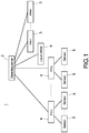
- the detecting server 2 can directly connect with each apparatus, or alternatively connect to each PAH 3 and the liquid chiller 6 through a programmable logic controller (PLC, not shown in Fig.1 ), and connect to each FCU 4 through zone controller(s) (ZC(s), not shown in Fig.1 ) arranged in each area.
- PLC programmable logic controller
- ZC zone controller(s)
- the plurality of sensors 5 in this embodiment are arranged in each area respectively, which are connected to the FCU 4 of the same arranged area, and connected to the detecting server 2 through each connected FCU 4.
- the system 1 is adopted in a building (not shown), the building includes several floors, and each floor has a space (such as space P1 shown in Fig.2 ). In the following description, a single space P1 will be taken as an example.
- the detecting server 2 segments the space P1 logically into several blocks with the same size (such as blocks S i shown in Fig.2 ).
- the space P1 is physically and generally decorated as multiple areas (such as lobby, offices, first meeting room, second meeting room, etc.), wherein each area is composed logically of different numbers of the blocks S i , i.e., the detecting server 2 defines each of the areas through the combination of the plurality of blocks S i .
- Fig.2 is a schematic view showing blocks segment of a first embodiment according to the present invention.
- the space P1 is logically segmented by the detecting server 2 into the plurality of blocks S i .
- the detecting server 2 segments the space P1 logically into forty-nine blocks S i , i.e., S 1 to S 49 of the same size shown in Fig.2 .
- the plurality of blocks S i ⁇ S 1 ,S 2 ,.........,S 49 ⁇
- the size of the space P1 equals to the sum of the sizes of the plurality of blocks S i .
- the space P1 includes a first area A1 (such as first meeting room (R-101)), a second area A2 (such as second meeting room (R-102)), a third area A3 (such as third meeting room (R-103)), a fourth area A4 (such as lobby) and a fifth area A5 (such as stairs area).
- the detecting server 2 can perform an automatic analysis algorithm, or receive a manager setting from a human-machine interface (HMI, not shown), so as to group the plurality of blocks S i respectively into each of the areas.
- HMI human-machine interface
- the detecting server 2 relates numbers of the blocks S 1 , S 2 , S 3 , S 8 , S 9 , S 10 , S 15 , S 16 and S 17 with the first area A1, relates numbers of the blocks S 5 , S 6 , S 7 , S 12 , S 13 , S 14 , S 19 , S 20 , S 21 , S 26 , S 27 and S 28 with the second area A2, relates numbers of the blocks S 29 , S 30 , S 31 , S 36 , S 37 , S 38 , S 43 , S 44 and S 45 with the third area A3, relates numbers of the blocks S 11 , S 18 , S 24 , S 25 , S 32 , S 33 , S 34 , S 35 , S 39 , S 40 , S 41 , S 42 , S 46 , S 47 , S 48 and S 49 with the fourth area A4, and relates the block S 4 with the fifth area A5.
- each of the blocks S i in the present invention has a minimal size which cannot be further segmented, for example, size of 20cm x 20cm or size of 10cm x 10cm, and the blocks S i are not overlapped with each other. Accordingly, the operation of the system 1 is not affected even the physical size of an area is not exactly equal to the sum of the sizes of the plurality of blocks S i constituting the area. Therefore, the difficulty of setting each of the areas is reduced.
- Each of the plurality of sensors 5 is respectively corresponding to one of the areas in order to sense the indoor environment of each area and transmit sensing data back to the detecting server 2. Therefore, the detecting server 2 can monitor each area for sensing abnormality through analyzing the sensing data.
- Each of the plurality of apparatuses is corresponding to each of the areas, accepts the detecting server's control to operate, and records apparatus parameters during their operation (detailed discussion in the following). More specifically, each apparatus can be corresponding to one or more areas, but not limited thereto.
- one FCU 4 is usually corresponding to a single area
- one PAH 3 is usually corresponding to multiple areas simultaneously (i.e., one PAH 3 takes charge of areas related to multiple FCUs 4)
- one liquid chiller 6 is usually corresponding to all areas of the same space P1 (i.e., one liquid chiller 6 takes charge of areas related to multiple FCUs 4 and multiple PAH 3).
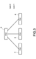
- FIG.3 a schematic view showing apparatuses coverage of a first embodiment according to the present invention.
- different types of apparatuses can take charge of different ranges of space and are classified into different levels.
- each of the FCUs 4 only blows air to a single area and is regarded as level 1, each of the PAHs 3 can simultaneously transmit outdoor air to multiple FCUs 4 and is regarded as level 2.
- the area related to the PAH 3 is overlapped with the areas respectively related to three of the FCUs 4 at the same time.
- Fig.4 is a block diagram of detecting server of a first embodiment according to the present invention.
- the detecting server 2 includes a processor 21, and also includes a block segmenting unit 22, a setting unit 23, a storage unit 24 and a communicating unit 25 which are all connected with the processor 21.
- each of the units 21-25 of the detecting server 2 is implemented through hardware (such as electronic circuit or integrated circuit), or implemented through software (such as program and application programming interface (API)), but not limited thereto.
- API application programming interface
- the setting unit 23 is used to set the size of the plurality of blocks S i for generating a setting value, and the block segmenting unit 22 segments the space P1 logically into the plurality of blocks S i according to the setting value of the setting unit 23.
- the setting unit 23 is also used to group the blocks S i respectively into each of the areas.
- the setting unit 23 is also used to relate the sensors and the apparatuses with each of the areas. In other words, the setting unit 23 sets each of the areas as a serving area (SA) where the sensors and the apparatuses take charge of.
- SA serving area
- the setting step of the aforementioned setting unit 23 is automatically executed through an algorithm.
- the setting unit 23 can be provided with a human-machine interface (HMI), and the setting unit 23 accepts a manager setting through the HMI. Therefore, a manager of the system 1 can manually and arbitrarily set the relationship between each of the areas and each of the blocks S i , the relationship between each of the sensors 5 and each of the areas, and the relationship between each of the apparatuses and each of the areas, and the system 1 can record these information in the storage unit 24.
- HMI human-machine interface
- the communication unit 25 is connected with the sensors and the apparatuses, receives the sensing data transmitted from the sensors, and transmits control commands to the apparatuses.
- the processor 21 receives the sensing data transmitted from the sensors 5 through the communication unit 25, and determines if an abnormality occurs according to the received sensing data. If determining that an abnormality occurs through analyzing the sensing data transmitted from a specific sensor of the plurality of sensors 5, the processor 21 first confirms an abnormal area and an occurring time of the abnormality, and obtains apparatus parameters of specific apparatuses corresponding to the abnormal area that are recorded at the occurring time.
- the abnormal area indicates the area where the abnormality occurred, and the abnormal area is the serving area where the specific sensor and the specific apparatuses take charge of.
- the processor 21 determines whether an abnormality occurs according to preset rules. For example, after a plurality of apparatuses of an area boot, the processor 21 continues receiving the sensing data to obtain indoor temperature of the area. If the indoor temperature of the area cannot be improved to meet a target temperature in a preset time period, the processor 21 will determine that an abnormality occurs in the area.
- the processor 21 After receiving the apparatus parameters from the specific apparatuses, the processor 21 then determines the occurring reason for the abnormality according to the apparatus parameters.
- the apparatus parameters of the apparatuses includes control parameters which is readable and writable and property parameters which is only readable.
- the processor 21 determines, according to the control parameters and the property parameters, that the occurring reason for the abnormality to be mis-controlled of the system 1 or the manager to the apparatuses, lack of capacity of the apparatuses, or environmental problems of the abnormal area itself.
- control parameters are corresponding to the control commands sent by the detecting server 2, such as the control commands for changing fan speed or valve degree of the FCUs 4, changing fan speed of the PAHs 3, etc..
- the property parameters are corresponding to each value of the apparatuses themselves, such as discharging temperature of the PAHs 3, power consumption of the FCUs 4, temperature of air that inhaling to the coil, etc..
- the sensors may include environmental sensors for sensing environment status of each of the serving areas, and apparatus sensors for sensing apparatus status of each of the apparatuses.
- Each of the environmental sensors is respectively arranged in a corresponding one of the serving areas, and includes person detector (PD) for sensing if a person enters the serving areas, temperature sensor for sensing indoor temperature of the serving areas, humidity sensor for sensing indoor humidity of the serving areas, CO2 sensor for sensing CO2 quantity of the serving areas, etc.
- PD person detector
- Each of the apparatus sensors is respectively arranged inside or surrounding a corresponding one of the apparatuses, and is used to sense the property parameters of the apparatus.
- the storage unit 24 stores a plane figure 241, an area comparison table 242, a sensor comparison table 243 and an apparatus comparison table 244.
- the plane figure 241 records spatial data of the space P1.
- the block segmenting unit 22 segments the space P1 logically into the plurality of blocks S i according to the plane figure 241 and the setting value indicating the size of each of the blocks S i .
- the area comparison table 242 is generated after the setting unit 23 groups the plurality of blocks S i respectively into each of the areas, and the area comparison table 242 records the relationship between each of the areas and each of the blocks S i . More specifically, in the embodiment shown in Fig.2 , the contents of the area comparison table 242 can be expressed as below: Area Comparison Table Area Blocks S i First Area(R-101) S 1 , S 2 , S 3 , S 4 , S 9 , S 10 , S 15 , S 16 , S 17 Second Area(R-102) S 5 , S 6 , S 7 , S 12 , S 13 , S 14 , S 19 , S 20 , S 21 , S 26 , S 27 and S 28 Third Area(R-103) S 29 , S 30 , S 31 , S 36 , S 37 , S 38 , S 43 , S 44 and S 45 Fourth Area(Lobby) S 11 , S 18 , S 24 , S 25 , S 32 , S 33 ,
- the technical effect which can be achieved by the present invention through grouping the plurality of blocks S i respectively to constitute each of the areas is that a new area can be easily re-defined through the plurality of blocks S i whenever the space P1 has greatly changed (such as redecorated) and causes the variation of sizes, numbers and positions of the areas in the space P1, and the algorithm adopted by the detecting server 2 does not need to be modified additionally. Therefore, the cost of both money and time for adjusting the system 1 can be greately saved.
- the sensor comparison table 243 is generated after the setting unit 23 relates the plurality of sensors 5 respectively to each of the serving areas, and the sensor comparison table 243 records the relationship between each of the sensors 5 and each of the serving areas. Also, if the sensors 5 include the aforementioned apparatus sensors, then the sensor comparison table 243 further records the relationship between each of the sensors 5 and each of the apparatuses.
- the contents of the sensor comparison table 243 can be expressed as below: Sensor Comparison Table Sensors Serving Areas Data Properties Sensor-T1 R-101 Temp Sensor-C1 R-101 CO2 Quantity Sensor-T2 R-102 Temp Sensor-C2 R-102 CO2 Quantity Sensor-T3 Lobby Temp Sensor-C3 Lobby CO2 Quantity Sensor-T4 Lobby Temp Sensor-C4 Lobby CO2 Quantity Sensor-T5 R-103 Temp Sensor-C5 R-103 CO2 Quantity Sensor-T6 Air Intake of PAH-01 Inhaling Air Temp Sensor-T7 Air Outlet of PAH-01 Discharging Air Temp
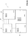
- Fig.5A is a schematic view showing sensor serving areas of a first embodiment according to the present invention.
- the serving area of sensor-T1 and sensor-C1 is the first meeting room R-101
- the serving area of sensot-T2 and sensor-C2 is the second meeting room R-102
- the serving area of sensor-T3, sensor-T4, sensor-C3 and sensor-C4 is lobby
- the serving area of sensor-T5 and sensor-C5 is the third meeting room R-103.
- sensors T1 to T5 are temperature sensors and the data properties of sensors T1 to T5 are temperatures (Temp)
- sensors C1 to C5 are CO2 sensors and the data properties of sensor C1 to C5 are CO2 quantities.
- sensor-T6 and sensor-T7 are apparatus sensors, which are respectively arranged surrounding PAH-01 (not shown in Fig.5A ). Both sensor-T6 and sensor-T7 are for temperature (i.e., temperature sensors), wherein the data property of sensor-T6 is inhaling air temperature of PAH-01, and the data property of sensor-T7 is discharging temperature of PAH-01. That is to say, the serving area of sensor-T6 is the air intake of PAH-01, and the serving area of sensor-T7 is the outlet of PAH-01.
- temperature sensors i.e., temperature sensors
- the apparatus comparison table 244 is generated after the setting unit 23 relates the plurality of apparatuses respectively to each of the serving areas, and the apparatus comparison table 244 records the relationship between each of the apparatuses and each of the serving areas. Also, the apparatus comparison table 244 further records the covering relations among all of the apparatuses.
- several apparatuses at lease includes multiple PAHs 3 and multiple FCUs 4, wherein every PAH 3 covers at least one FCU 4.
- every PAH 3 covers at least one FCU 4.
- a specific PAH covers a specific FCU, it means parts of the serving area of the specific PAH is overlapped with the serving area of the specific FCU.
- the contents of the apparatus comparison table 244 can be expressed as below: Apparatus Comparison Table Apparatuses Serving Areas Covering Relations FCU-01 R-101 PAH-01 FCU-02 R-102 PAH-01 FCU-03 lobby PAH-02 FCU-04 lobby PAH-02 FCU-05 R-103 PAH-02 PAH-01 R-101, R-102 Liquid Chiller PAH-02 R-103, lobby Liquid Chiller Liquid Chiller R-101, R-102, R-103, lobby none
- Fig.5B is a schematic view showing FCU serving areas of a first embodiment according to the present invention
- Fig.5C is a schematic view showing FCU serving areas of a first embodiment according to the present invention.
- the serving area of FCU-01 is the first meeting room R-101 and is covered by PAH-01.
- the serving area of FCU-02 is the second meeting room R-102 and is covered by PAH-01.
- the serving area of FCU-03 and FCU-04 is lobby and is covered by PAH-02.
- the serving area of FCU-05 is the third meeting room R-103 and is covered by PAH-02.
- the serving area of PAH-01 is the first meeting room R-101 and the second meeting room R-102
- the serving area of PAH-02 is the third meeting room R-103 and lobby.
- both of the serving areas of PAH-01 and PAH-02 are covered with the liquid chiller 6.
- the serving area of the liquid chiller 6 covers all areas inside the space P1, i.e., it covers the first meeting room R-101, the second meeting room R-102, the third meeting room R-103 and lobby at the same time.
- Fig.6 is a relationship tree diagram of a first embodiment according to the present invention.
- the detecting server 2 can automatically generate the tree diagram shown in Fig.6 .
- the liquid chiller 6 covers the serving areas of each of the FCUs 4 and each of the PAHs 3 at the same time, and directly drains icy water to each of the FCUs 4 and each of the PAHs 3.
- What is disclosed in Fig.6 is just the tree figure showing the covering relations among these apparatuses 3, 4 and 6, but not the diagram showing the actual connecting relations among these apparatuses 3, 4 and 6.
- the serving area of sensor-T1, sensor-C1 and FCU-01 is the first meeting room R-101, and the first meeting room R-101 is covered with PAH-01.
- the serving area of sensor-T2, sensor-C2 and FCU-02 is the second meeting room R-102, and the second meeting room R-102 is covered with PAH-01.
- the serving area of sensor-T3, sensor-T4, sensor-C3, sensor-C4, FCU-03 and FCU-04 is lobby, and lobby is covered with PAH-02.
- the serving area of sensor-T5, sensor-C5 and FCU-05 is the third meeting room R-103, and the third meeting room R-103 is covered with PAH-02. Also, both of PAH-01 and PAH-02 are covered with the liquid chiller 6.
- the detecting server 2 determines whether an abnormality occurs in the first meeting room R-101 according to the sensing data of sensor-T1 and sensor-C1.
- the detecting server 2 obtains the apparatus parameters from FCU-01, PAH-01 and the liquid chiller 6 in order to determine the occurring reason for the abnormality.
- the detecting server 2 determines whether an abnormality occurs in the second meeting room R-102 according to the sensing data of sensor-T2 and sensor-C2. When the abnormality is determined to occur in the second meeting room R-102, the detecting server 2 obtains the apparatus parameters from FCU-02, PAH-01 and the liquid chiller 6 in order to determine the occurring reason for the abnormality.
- the detecting server 2 determines whether an abnormality occurs in lobby according to the sensing data of sensor-T3, sensor-T4, sensor-C3 and sensor-C4. When the abnormality is determined to occur in lobby, the detecting server 2 obtains the apparatus parameters from FCU-03, FCU-04, PAH-02 and the liquid chiller 6 in order to determine the occurring reason for the abnormality.
- the detecting server 2 determines whether an abnormality occurs in the third meeting room R-103 according to the sensing data of sensor-T5 and sensor-C5. When the abnormality is determined to occur in the third meeting room R-103, the detecting server 2 obtains the apparatus parameters from FCU-05, PAH-02 and the liquid chiller 6 in order to determine the occurring reason for the abnormality.
- the storage unit 24 further stores an abnormality serial table 245.
- the detecting server 2 continues receiving the sensing data from the sensors 5, and updates the abnormality serial table 245 regularly according to the received sensing data.
- the detecting server 2 sets a flag in a corresponding column of the abnormality serial table 245 as "0" if it determines no abnormality occurs based on the sensing data, and sets the flag in the corresponding column of the abnormality serial table 245 as "1" if it determines an abnormality does occur based on the sensing data.
- the detecting server 2 simultaneously records the abnormal area and the occurring time of the abnormality in the corresponding column of the abnormality serial table 245.
- the abnormality serial table 245 can help the detecting server 2 to gather the time periods that the abnormalities respectively occur in each area, and assists the detecting server 2 to generate a time distributed diagram. Therefore, the time distributed diagram is beneficial to the detecting server 2 to determine whether the occurring reason for a determined abnormality is related to environment, time or outdoor climate.
- Fig.7 is an abnormality detecting flowchart of a first embodiment according to the present invention.
- the present invention further discloses an area abnormality detecting method (refers to as the method hereinafter); the method is adopted in the aforementioned system 1, and includes the following steps.
- the system 1 segments the space P1 logically into the plurality of blocks S i with the same size (step S10).
- the system 1 After completing the setting of the areas, the sensors 5 and the apparatuses, the system 1 is ready to operate. Next, the system 1 continues receiving the sensing data transmitted from the sensors 5 during the operation (step S16), wherein the sensing data transmitted by each sensor 5 is corresponding to the serving area taken charge by the sensor 5. Also, according to the contents of the sensing data (for example, the sensing data indicates a person enters one of the serving areas), each of the apparatuses can accept control of the system 1 to operate for the corresponding serving area(s), and records its own apparatus parameters when operating.
- the system 1 determines if an abnormality occurs in each of the areas according to the sensing data transmitted from each of the sensors (step S18). If there is no determined abnormality, the system 1 goes back to the step S14 and continues receiving the sensing data and detecting the occurrence of abnormality.
- the system 1 first confirms an abnormal area and an occurring time of the abnormality (step S20).
- the system 1 determines the abnormality occurs according to the sensing data transmitted from a specific sensor of the plurality of sensors 5, and the abnormal area is the specific sensor's serving area.
- the occurring time is the time the abnormality occurred, and it can include year, month, day, hours, minute and second, but not limited thereto.
- the system 1 After confirming the abnormal area and the occurring time, the system 1 further obtains the apparatus parameters of specific apparatuses corresponding to the abnormal area that are recorded at the occurring time (step S22).
- the abnormal area is the serving area of the specific apparatuses
- the specific apparatuses can include the FCU(s) 4, the PAH(s) 3 and the liquid chiller 6, but not limited thereto.
- the aforementioned serving areas represent target areas where the apparatuses provide the environmental improving services for, but the entities of the apparatuses are not necessary to be arranged inside the serving areas. Moreover, these apparatuses can be arranged out of the space P1 (for example, in the outside or the basement of the building), but not limited thereto.
- the system 1 can determine the occurring reason for the abnormality according to the obtained apparatus parameters (step S24).
- the aforementioned apparatus comparison table 244 further records arranged areas of each of the apparatuses, therefore, whenever the system 1 determines the occurring reason for the abnormality is that one of the apparatuses lacks of capacity, it can obtain the arranged area of the apparatus from the apparatus comparison table 244 and asks staffs to go to the arranged area for maintaining or replacing the apparatus. Also, if the arranged area is located inside the space P1, the system 1 can define the arranged area through the plurality of blocks S i .
- Fig.8 is an area relating flowchart of a first embodiment according to the present invention.
- the system 1 first obtains the plane figure 241 of the space P1 from the storage unit 24 (step S30), and obtains a block setting value from the setting unit 23 (step S32), wherein the block setting value is the size that is set for the plurality of blocks S i . Therefore, the system 1 segments the space P1 logically into the plurality of blocks S i according to the plane figure 241 and the block setting value (step S34).
- each of the plurality of blocks S i respectively has a minimal size which cannot be further segmented, and they are not overlapped with each other.
- the system 1 When defining each of the areas, the system 1 mainly executes an area setting procedure, so as to group the plurality of blocks S i respectively into each of the areas (step S36).
- the system 1 When defining the serving areas respectively for each of the sensors, the system 1 mainly executes a sensor setting procedure, so as to set the areas respectively as the serving areas for each of the sensors (step S38).
- the system 1 When defining the serving areas respectively for each of the apparatuses, the system 1 mainly executes an apparatus setting procedure, so as to set the areas respectively as the serving areas for each of the apparatuses (step S40).
- the system 1 generates the area comparison table 242 through the execution of the area setting procedure, and stores the area comparison table 242 to the storage unit 24.
- the area comparison table 242 records the relationship between each of the areas and each of the blocks S i which is set by the execution of the area setting procedure.
- the system 1 generates the sensor comparison table 243 and the apparatus comparison table 244 through the execution of the sensor setting procedure and the apparatus setting procedure, and stores these two tables 243 and 244 to the storage unit 24.
- the sensor comparison table 243 records the relationship between the sensors 5 and their serving areas which is set by the execution of the sensor comparison table 243
- the apparatus comparison table 244 records the relationship between the apparatuses and their serving areas which is set by the execution of the apparatus comparison table 244.
- Fig.9 is an abnormality recording flowchart of a first embodiment according to the present invention.
- the system 1 can receive a target comfort degree of the entered serving area (step S50).
- a person detector inside the serving area will notify the system 1 whenever it detects a person enters the serving area, and then the system 1 can further receive the target comfort degree.
- the target comfort degree is set manually by the person who enters the serving area, or is a default value preset by the system 1 or the manager of the system 1, but not limited thereto.
- the system 1 controls the apparatuses which take charge of the serving area to operate (step S52), so as to provide the environmental improving services for the serving area. Therefore, the system 1 makes the indoor environment of the serving area can meet the target comfort degree in a preset time period.
- the target comfort degree can be, for example, target temperature, target humidity, target CO2 quantity or target comfort index (or so called predicted mean vote (PMV)), but not limited thereto.
- each of the apparatuses continues recording its own apparatus parameters when operating (step S54).
- the system 1 continues receiving the sensing data from the sensors 5 after the apparatuses are operating, and the system 1 determines if any abnormality occurs according to the received sensing data (step S56).
- the system 1 in this embodiment is to determine if any abnormality occurs in one or more serving areas having the target comfort degree, but not limited.
- the system 1 updates the abnormal serial table 245 regularly according to the sensing data, sets the flag of the corresponding column of the abnormal serial table 245 as "0" if there is no abnormality is determined to occur (step S58), and sets the flag of the corresponding column of the abnormal serial table 245 as "1" if any abnormality occurs (step S60).
- the system 1 determines to power off the apparatuses or not (step S62). In particularly, the system 1 determines to power off the apparatuses or not according to the condition whether the person inside the serving area is leaving or not. Also, the system 1 re-executes the step S52 to the step S60 before the apparatuses are not powered off, so as to continue detecting the abnormality and updating the abnormal serial table 245.
- Fig.10 is an abnormality processing flowchart of a first embodiment according to the present invention.
- the system 1 or the manager of the system 1 needs to analyze the abnormalities of the space P1, it can extract all the flags that have been set as "1" from the abnormal serial table 245, so as to obtain the abnormal areas and the occurring times corresponding to all of the abnormalities (step S70). Next, it can obtain the apparatus parameters of the plurality of apparatuses corresponding to the abnormal areas that are respectively recorded at the occurring times (step S72).
- the apparatus parameters may include the control parameters, which are readable and writable, and the property parameters, which are only readable.
- the system 1 determines the occurring reason for the abnormalities to be mis-controlled of the system 1 or the manager to the apparatuses, lack of capacity of the apparatuses (for example, the apparatuses are too old, or the amount of the apparatuses in the area is not enough), or the environmental problem of the abnormal area itself (for example, windows are opened, or a high temperature machine is using) according to both of the property parameters and the control parameters (step S74).
- the system 1 can obtain the arranged areas of the apparatuses corresponding to the abnormal areas when determining that the occurring reason for the abnormalities is the problems of the apparatuses, and then sends a maintaining notification according to the arranged areas (step S76). Therefore, the staffs can go to the arranged areas to maintain, update or replace for each of the apparatuses.
- the system 1 can obtain all the flags had been set as "1" from the abnormal serial table 245 to obtain the occurring times respectively corresponding to all of the abnormalities, so as to generate the time distributed diagram thereupon (step S78).
- the manager can be easily notified the regular occurring time of the abnormalities, so as to determine the occurring reason for each abnormality. For example, if an abnormality usually occurs in first meeting room on Monday PM.3:00, in this case, the abnormality may occur because too many people are regularly there in the first meeting room on Monday PM.3:00.
- the system 1 in the present invention is to input the operating status of the apparatuses and the current indoor environment of the corresponding serving area into a self-defined rules, so as to determine whether an abnormality occurs in the serving area.
- the self-defined rules can set a condition that the abnormality is regarded to occur when indoor temperature of the serving area cannot meet a tarter temperature in five minutes afther the PAH 3 is booted, and then a corresponding flag of the abnormal serial table 245 will be set as "1".
- Fig. 11 is a schematic view showing abnormality serial table of a first embodiment according to the present invention.
- the system 1 updates the abnormal serial table 245 regularly (once in every five minutes, for example), according to the sensing data transmitted from the sensors 5.
- the system 1 sets a flag in a corresponding column of the abnormal serial table 245 as "1".
- the system 1 also records both the abnormal area and the occurring time of the abnormality in the corresponding column, wherein the abnormal area is the serving area taken charge by the specific sensor that transmits the sensing data, and the occurring time is the transmitting time of the sensing data.
- the abnormal area of a first one of the two abnormalities is the first meeting room R-101, and the occurring time of the first abnormality is PM1:05.
- the abnormal area of a second one of the two abnormalities is the third meeting room R-103, and the occurring time of the second abnormality is PM1:20.
- the system 1 can then obtain the apparatus parameters of FCU-01 and PAH-01 taking charge of the first meeting room R-101 that are recorded at PM1:05, and inputs the apparatus parameters to an algorithm to analyze the occurring reason of the first abnormality. Also, the system 1 can obtain the apparatus parameters of FCU-05 and PAH-02 taking charging of the third meeting room R-103 that are recorded at PM1:20, and inputs the apparatus parameters to the algorithm to analyze the occuring reason of the second abnormality.
- the manager can easily find out the occurring reason for any abnormality occurs in each area. Also, even the areas inside a building are re-defined somehow, the algorithm adopted by the system 1 is not necessary to be modified, so the cost of both time and money in adjusting the system 1 can be effectively reduced.
Landscapes
- Engineering & Computer Science (AREA)
- General Engineering & Computer Science (AREA)
- Chemical & Material Sciences (AREA)
- Combustion & Propulsion (AREA)
- Mechanical Engineering (AREA)
- Physics & Mathematics (AREA)
- Signal Processing (AREA)
- General Physics & Mathematics (AREA)
- Automation & Control Theory (AREA)
- Fluid Mechanics (AREA)
- Fuzzy Systems (AREA)
- Mathematical Physics (AREA)
- Air Conditioning Control Device (AREA)
Abstract
Description
- The invention relates to a detecting system and a detecting method, and in particularly to an area abnormality detecting system and an area abnormality detecting method.
- In order to adjust comfort degree of indoor space temperature the modem buildings now are usually arranged with centrol air-conditioning systems, and use indoor apparatuses, such as pre-cooling air handling units (PAHs), fan coil units (FCUs), etc., to blow cold air into the buildings. Also, the buildings use a lot of sensors to detect various environmental statuses inside the buildings.
- General speaking, these indoor apparatuses and sensors are usually corresponding to different areas inside the building, such as lobby, meeting rooms, working areas, spare rooms, etc.. The sensors are used to detect various environmental statuses, such as temperature, humidity and person existence, in each area, and each of the indoor apparatuses is used to improve environmental confort conditions, such as reducing indoor temperature, increasing indoor humidity, etc., in each area.
- Moreover, if the aforementioned centrol air-conditioning system is an intelligent air-conditioing system, then a manager of the system can preset, actual position of each area inside the building (such as coordinates), and the relationship among the indoor apparatuses, the sensors and each of the areas, in an intelligence controlling algorithm adopted by the system. Therefore, a processor therein can automatically control each of the indoor apparatuses to execute the improving services according to sensing data received from each of the sensors (for example, when a person is detected to enter a predetermined area, the processor automatically turns on an indoor apparatus which is corresponding to the predetermined area).
- As mentioned above, the current intellectual air-conditioning system usually pre-defines the positions of each area inside the building, and presets the relationship among the indoor apparatuses, the sensors and the areas. However, if the indoor spaces of the building have a great change (for example, the building is redecorated), the manager needs to reset corresponding parameters of the algorithm of the system according to the variation of the indoor spaces in order to rebuild the relationship among each of the indoor apparatuses, each of the sensors and each of the changed areas, which is very complicated.
- The main object of the present invention is to provide an area abnormality detecting system and an area abnormality detecting method, which constitute multiple areas of a space respectively by grouping a plurality of blocks having the same size, so as to easily define size, amount and position of each area of the space, and define serving areas of the space that multiple apparatuses and sensors take charge of.
- The other object of the present invention is to provide an area abnormality detecting system and an area abnormality detecting method, which obtain parameters of apparatuses corresponding to an abnormal area when an abnormality occurs, so as to determine the occurring reason for the abnormality.
- To achieve to above objects, an area abnormality detecting system including multiple apparatuses, multiple sensors and a detecting server is disclosed in the present invention. The system is adopted in a space, which is segmented into several blocks with the same size. Multiple areas of the space are defined by the blocks separately. The apparatuses are respectively corresponding to each area for providing environmental improving services. The sensors are respectively corresponding to each area for sensing indoor environment of each area.
- When an abnormality occurs, the detecting server determines an abnormal area and an occurring time corresponding to the abnormality, and then obtains several apparatus parameters of apparatuses corresponding to the abnormal area that are recorded at the occurring time, so as to determine the occurring reason for the abnormality based on the apparatus parameters.
- The present invention firstly segments the space into a plurality of blocks with same size, and defines the areas of the space by the plurality of blocks, and then relates the sensors and the apparatuses with each area which needs to be served. Therefore, when each of the areas of the space has greatly changed (redecoration for example), the system can re-define each area with the plurality of blocks quickly, and easily rebuild the relationship among the sensors, the apparatuses and the re-defined areas of the space.
-
-
Fig.1 is a schematic view showing system arrangement of a first embodiment according to the present invention. -
Fig.2 is a schematic view showing blocks segment of a first embodiment according to the present invention. -
Fig.3 is a schematic view showing apparatuses coverage of a first embodiment according to the present invention. -
Fig.4 is a block diagram of detecting server of a first embodiment according to the present invention. -
Fig.5A is a schematic view showing sensor serving areas of a first embodiment according to the present invention. -
Fig.5B is a schematic view showing FCU serving areas of a first embodiment according to the present invention. -
Fig.5C is a schematic view showing FCU serving areas of a first embodiment according to the present invention. -
Fig.6 is a relationship tree diagram of a first embodiment according to the present invention. -
Fig.7 is an abnormality detecting flowchart of a first embodiment according to the present invention. -
Fig.8 is an area relating flowchart of a first embodiment according to the present invention. -
Fig.9 is an abnormality recording flowchart of a first embodiment according to the present invention. -
Fig.10 is an abnormality processing flowchart of a first embodiment according to the present invention. -
Fig.11 is a schematic view showing abnormality serial table of a first embodiment according to the present invention. - In cooperation with the attached drawings, the technical contents and detailed description of the present invention are described thereinafter according to a preferable embodiment, being not used to limit its executing scope. Any equivalent variation and modification made according to appended claims is all covered by the claims claimed by the present invention.
- The detecting
server 2 can directly connect with each apparatus, or alternatively connect to eachPAH 3 and theliquid chiller 6 through a programmable logic controller (PLC, not shown inFig.1 ), and connect to eachFCU 4 through zone controller(s) (ZC(s), not shown inFig.1 ) arranged in each area. The plurality ofsensors 5 in this embodiment are arranged in each area respectively, which are connected to the FCU 4 of the same arranged area, and connected to the detectingserver 2 through each connected FCU 4. - The
system 1 is adopted in a building (not shown), the building includes several floors, and each floor has a space (such as space P1 shown inFig.2 ). In the following description, a single space P1 will be taken as an example. - In the present invention, the
detecting server 2 segments the space P1 logically into several blocks with the same size (such as blocks Si shown inFig.2 ). The space P1 is physically and generally decorated as multiple areas (such as lobby, offices, first meeting room, second meeting room, etc.), wherein each area is composed logically of different numbers of the blocks Si, i.e., the detectingserver 2 defines each of the areas through the combination of the plurality of blocks Si. -
Fig.2 is a schematic view showing blocks segment of a first embodiment according to the present invention. InFig.2 , the space P1 is logically segmented by the detectingserver 2 into the plurality of blocks Si. In particularly, the detectingserver 2 segments the space P1 logically into forty-nine blocks Si, i.e., S1 to S49 of the same size shown inFig.2 . In other words, the plurality of blocks Si = {S1,S2,.........,S49}, and the size of the space P1 equals to the sum of the sizes of the plurality of blocks Si. - As shown in
Fig.2 , the space P1 includes a first area A1 (such as first meeting room (R-101)), a second area A2 (such as second meeting room (R-102)), a third area A3 (such as third meeting room (R-103)), a fourth area A4 (such as lobby) and a fifth area A5 (such as stairs area). In the present invention, the detectingserver 2 can perform an automatic analysis algorithm, or receive a manager setting from a human-machine interface (HMI, not shown), so as to group the plurality of blocks Si respectively into each of the areas. - More specifically, in the embodiment of
Fig.2 , the detectingserver 2 relates numbers of the blocks S1, S2, S3, S8, S9, S10, S15, S16 and S17 with the first area A1, relates numbers of the blocks S5, S6, S7, S12, S13, S14, S19, S20, S21, S26, S27 and S28 with the second area A2, relates numbers of the blocks S29, S30, S31, S36, S37, S38, S43, S44 and S45 with the third area A3, relates numbers of the blocks S11, S18, S24, S25, S32, S33, S34, S35, S39, S40, S41, S42, S46, S47, S48 and S49 with the fourth area A4, and relates the block S4 with the fifth area A5. - It should be mentioned that each of the blocks Si in the present invention has a minimal size which cannot be further segmented, for example, size of 20cm x 20cm or size of 10cm x 10cm, and the blocks Si are not overlapped with each other. Accordingly, the operation of the
system 1 is not affected even the physical size of an area is not exactly equal to the sum of the sizes of the plurality of blocks Si constituting the area. Therefore, the difficulty of setting each of the areas is reduced. - Refer to
Fig.1 again. Each of the plurality ofsensors 5 is respectively corresponding to one of the areas in order to sense the indoor environment of each area and transmit sensing data back to the detectingserver 2. Therefore, the detectingserver 2 can monitor each area for sensing abnormality through analyzing the sensing data. - Each of the plurality of apparatuses is corresponding to each of the areas, accepts the detecting server's control to operate, and records apparatus parameters during their operation (detailed discussion in the following). More specifically, each apparatus can be corresponding to one or more areas, but not limited thereto. For example, one
FCU 4 is usually corresponding to a single area, onePAH 3 is usually corresponding to multiple areas simultaneously (i.e., onePAH 3 takes charge of areas related to multiple FCUs 4), and oneliquid chiller 6 is usually corresponding to all areas of the same space P1 (i.e., oneliquid chiller 6 takes charge of areas related tomultiple FCUs 4 and multiple PAH 3). - Please also refer to
Fig.3 , a schematic view showing apparatuses coverage of a first embodiment according to the present invention. As mentioned above, different types of apparatuses can take charge of different ranges of space and are classified into different levels. As shown inFig.3 , each of theFCUs 4 only blows air to a single area and is regarded aslevel 1, each of thePAHs 3 can simultaneously transmit outdoor air to multiple FCUs 4 and is regarded aslevel 2. In the embodiment ofFig.3 , the area related to thePAH 3 is overlapped with the areas respectively related to three of theFCUs 4 at the same time. -
Fig.4 is a block diagram of detecting server of a first embodiment according to the present invention. As shown inFig.4 , the detectingserver 2 includes aprocessor 21, and also includes ablock segmenting unit 22, asetting unit 23, astorage unit 24 and a communicatingunit 25 which are all connected with theprocessor 21. In this embodiment, each of the units 21-25 of the detectingserver 2 is implemented through hardware (such as electronic circuit or integrated circuit), or implemented through software (such as program and application programming interface (API)), but not limited thereto. - The setting
unit 23 is used to set the size of the plurality of blocks Si for generating a setting value, and theblock segmenting unit 22 segments the space P1 logically into the plurality of blocks Si according to the setting value of thesetting unit 23. The settingunit 23 is also used to group the blocks Si respectively into each of the areas. Furthermore, the settingunit 23 is also used to relate the sensors and the apparatuses with each of the areas. In other words, the settingunit 23 sets each of the areas as a serving area (SA) where the sensors and the apparatuses take charge of. - In one embodiment, the setting step of the
aforementioned setting unit 23 is automatically executed through an algorithm. In other embodiments, however, the settingunit 23 can be provided with a human-machine interface (HMI), and thesetting unit 23 accepts a manager setting through the HMI. Therefore, a manager of thesystem 1 can manually and arbitrarily set the relationship between each of the areas and each of the blocks Si, the relationship between each of thesensors 5 and each of the areas, and the relationship between each of the apparatuses and each of the areas, and thesystem 1 can record these information in thestorage unit 24. - The
communication unit 25 is connected with the sensors and the apparatuses, receives the sensing data transmitted from the sensors, and transmits control commands to the apparatuses. - The
processor 21 receives the sensing data transmitted from thesensors 5 through thecommunication unit 25, and determines if an abnormality occurs according to the received sensing data. If determining that an abnormality occurs through analyzing the sensing data transmitted from a specific sensor of the plurality ofsensors 5, theprocessor 21 first confirms an abnormal area and an occurring time of the abnormality, and obtains apparatus parameters of specific apparatuses corresponding to the abnormal area that are recorded at the occurring time. In this embodiment, the abnormal area indicates the area where the abnormality occurred, and the abnormal area is the serving area where the specific sensor and the specific apparatuses take charge of. - It should be mentioned that the
processor 21 determines whether an abnormality occurs according to preset rules. For example, after a plurality of apparatuses of an area boot, theprocessor 21 continues receiving the sensing data to obtain indoor temperature of the area. If the indoor temperature of the area cannot be improved to meet a target temperature in a preset time period, theprocessor 21 will determine that an abnormality occurs in the area. - After receiving the apparatus parameters from the specific apparatuses, the
processor 21 then determines the occurring reason for the abnormality according to the apparatus parameters. In particularly, the apparatus parameters of the apparatuses includes control parameters which is readable and writable and property parameters which is only readable. Theprocessor 21 determines, according to the control parameters and the property parameters, that the occurring reason for the abnormality to be mis-controlled of thesystem 1 or the manager to the apparatuses, lack of capacity of the apparatuses, or environmental problems of the abnormal area itself. - In this embodiment, the control parameters are corresponding to the control commands sent by the detecting
server 2, such as the control commands for changing fan speed or valve degree of theFCUs 4, changing fan speed of thePAHs 3, etc.. The property parameters are corresponding to each value of the apparatuses themselves, such as discharging temperature of thePAHs 3, power consumption of theFCUs 4, temperature of air that inhaling to the coil, etc.. - The sensors may include environmental sensors for sensing environment status of each of the serving areas, and apparatus sensors for sensing apparatus status of each of the apparatuses. Each of the environmental sensors is respectively arranged in a corresponding one of the serving areas, and includes person detector (PD) for sensing if a person enters the serving areas, temperature sensor for sensing indoor temperature of the serving areas, humidity sensor for sensing indoor humidity of the serving areas, CO2 sensor for sensing CO2 quantity of the serving areas, etc.. Each of the apparatus sensors is respectively arranged inside or surrounding a corresponding one of the apparatuses, and is used to sense the property parameters of the apparatus.
- The
storage unit 24 stores a plane figure 241, an area comparison table 242, a sensor comparison table 243 and an apparatus comparison table 244. The plane figure 241 records spatial data of the space P1. In particularly, theblock segmenting unit 22 segments the space P1 logically into the plurality of blocks Si according to the plane figure 241 and the setting value indicating the size of each of the blocks Si. - The area comparison table 242 is generated after the
setting unit 23 groups the plurality of blocks Si respectively into each of the areas, and the area comparison table 242 records the relationship between each of the areas and each of the blocks Si. More specifically, in the embodiment shown inFig.2 , the contents of the area comparison table 242 can be expressed as below:Area Comparison Table Area Blocks Si First Area(R-101) S1, S2, S3, S4, S9, S10, S15, S16, S17 Second Area(R-102) S5, S6, S7, S12, S13, S14, S19, S20, S21, S26, S27 and S28 Third Area(R-103) S29, S30, S31, S36, S37, S38, S43, S44 and S45 Fourth Area(Lobby) S11, S18, S24, S25, S32, S33, S34, S35, S39, S40, S41, S42, S46, S47, S48 and S49 Fifth Area(Stairs Area) S4 - The technical effect which can be achieved by the present invention through grouping the plurality of blocks Si respectively to constitute each of the areas is that a new area can be easily re-defined through the plurality of blocks Si whenever the space P1 has greatly changed (such as redecorated) and causes the variation of sizes, numbers and positions of the areas in the space P1, and the algorithm adopted by the detecting
server 2 does not need to be modified additionally. Therefore, the cost of both money and time for adjusting thesystem 1 can be greately saved. - The sensor comparison table 243 is generated after the
setting unit 23 relates the plurality ofsensors 5 respectively to each of the serving areas, and the sensor comparison table 243 records the relationship between each of thesensors 5 and each of the serving areas. Also, if thesensors 5 include the aforementioned apparatus sensors, then the sensor comparison table 243 further records the relationship between each of thesensors 5 and each of the apparatuses. More specifically, in the embodiment shown inFig.5A , the contents of the sensor comparison table 243 can be expressed as below:Sensor Comparison Table Sensors Serving Areas Data Properties Sensor-T1 R-101 Temp Sensor-C1 R-101 CO2 Quantity Sensor-T2 R-102 Temp Sensor-C2 R-102 CO2 Quantity Sensor-T3 Lobby Temp Sensor-C3 Lobby CO2 Quantity Sensor-T4 Lobby Temp Sensor-C4 Lobby CO2 Quantity Sensor-T5 R-103 Temp Sensor-C5 R-103 CO2 Quantity Sensor-T6 Air Intake of PAH-01 Inhaling Air Temp Sensor-T7 Air Outlet of PAH-01 Discharging Air Temp -
Fig.5A is a schematic view showing sensor serving areas of a first embodiment according to the present invention. In the embodiment ofFig.5A , the serving area of sensor-T1 and sensor-C1 is the first meeting room R-101, the serving area of sensot-T2 and sensor-C2 is the second meeting room R-102, the serving area of sensor-T3, sensor-T4, sensor-C3 and sensor-C4 is lobby, and the serving area of sensor-T5 and sensor-C5 is the third meeting room R-103. Specifically, sensors T1 to T5 are temperature sensors and the data properties of sensors T1 to T5 are temperatures (Temp), and sensors C1 to C5 are CO2 sensors and the data properties of sensor C1 to C5 are CO2 quantities. - In this embodiment, sensor-T6 and sensor-T7 are apparatus sensors, which are respectively arranged surrounding PAH-01 (not shown in
Fig.5A ). Both sensor-T6 and sensor-T7 are for temperature (i.e., temperature sensors), wherein the data property of sensor-T6 is inhaling air temperature of PAH-01, and the data property of sensor-T7 is discharging temperature of PAH-01. That is to say, the serving area of sensor-T6 is the air intake of PAH-01, and the serving area of sensor-T7 is the outlet of PAH-01. However, the above description is just an embodiment, not intended to limit the scope of the present invention. - The apparatus comparison table 244 is generated after the
setting unit 23 relates the plurality of apparatuses respectively to each of the serving areas, and the apparatus comparison table 244 records the relationship between each of the apparatuses and each of the serving areas. Also, the apparatus comparison table 244 further records the covering relations among all of the apparatuses. - In this embodiment, several apparatuses at lease includes
multiple PAHs 3 andmultiple FCUs 4, wherein everyPAH 3 covers at least oneFCU 4. In particularly, if a specific PAH covers a specific FCU, it means parts of the serving area of the specific PAH is overlapped with the serving area of the specific FCU. - More specifically, in the embodiment shown in
Fig.5B andFig.5C , the contents of the apparatus comparison table 244 can be expressed as below:Apparatus Comparison Table Apparatuses Serving Areas Covering Relations FCU-01 R-101 PAH-01 FCU-02 R-102 PAH-01 FCU-03 lobby PAH-02 FCU-04 lobby PAH-02 FCU-05 R-103 PAH-02 PAH-01 R-101, R-102 Liquid Chiller PAH-02 R-103, lobby Liquid Chiller Liquid Chiller R-101, R-102, R-103, lobby none -
Fig.5B is a schematic view showing FCU serving areas of a first embodiment according to the present invention, andFig.5C is a schematic view showing FCU serving areas of a first embodiment according to the present invention. In the embodiment ofFig.5B , the serving area of FCU-01 is the first meeting room R-101 and is covered by PAH-01. The serving area of FCU-02 is the second meeting room R-102 and is covered by PAH-01. The serving area of FCU-03 and FCU-04 is lobby and is covered by PAH-02. The serving area of FCU-05 is the third meeting room R-103 and is covered by PAH-02. - In the embodiment of
Fig.5C , the serving area of PAH-01 is the first meeting room R-101 and the second meeting room R-102, and the serving area of PAH-02 is the third meeting room R-103 and lobby. Also, both of the serving areas of PAH-01 and PAH-02 are covered with theliquid chiller 6. According to the apparatus comparison table 244, the serving area of theliquid chiller 6 covers all areas inside the space P1, i.e., it covers the first meeting room R-101, the second meeting room R-102, the third meeting room R-103 and lobby at the same time. -
Fig.6 is a relationship tree diagram of a first embodiment according to the present invention. According to the area comparison table 242, the sensor comparison table 243, the apparatus comparison table 244 and the contents disclosed inFig.5A to Fig.5C , the detectingserver 2 can automatically generate the tree diagram shown inFig.6 . Previously and generally, theliquid chiller 6 covers the serving areas of each of theFCUs 4 and each of thePAHs 3 at the same time, and directly drains icy water to each of theFCUs 4 and each of thePAHs 3. What is disclosed inFig.6 is just the tree figure showing the covering relations among theseapparatuses apparatuses - As shown in
Fig.6 , the serving area of sensor-T1, sensor-C1 and FCU-01 is the first meeting room R-101, and the first meeting room R-101 is covered with PAH-01. The serving area of sensor-T2, sensor-C2 and FCU-02 is the second meeting room R-102, and the second meeting room R-102 is covered with PAH-01. The serving area of sensor-T3, sensor-T4, sensor-C3, sensor-C4, FCU-03 and FCU-04 is lobby, and lobby is covered with PAH-02. The serving area of sensor-T5, sensor-C5 and FCU-05 is the third meeting room R-103, and the third meeting room R-103 is covered with PAH-02. Also, both of PAH-01 and PAH-02 are covered with theliquid chiller 6. - In particularly, the detecting
server 2 determines whether an abnormality occurs in the first meeting room R-101 according to the sensing data of sensor-T1 and sensor-C1. When the abnormality is determined to occur in the first meeting room R-101, the detectingserver 2 obtains the apparatus parameters from FCU-01, PAH-01 and theliquid chiller 6 in order to determine the occurring reason for the abnormality. - The detecting
server 2 determines whether an abnormality occurs in the second meeting room R-102 according to the sensing data of sensor-T2 and sensor-C2. When the abnormality is determined to occur in the second meeting room R-102, the detectingserver 2 obtains the apparatus parameters from FCU-02, PAH-01 and theliquid chiller 6 in order to determine the occurring reason for the abnormality. - The detecting
server 2 determines whether an abnormality occurs in lobby according to the sensing data of sensor-T3, sensor-T4, sensor-C3 and sensor-C4. When the abnormality is determined to occur in lobby, the detectingserver 2 obtains the apparatus parameters from FCU-03, FCU-04, PAH-02 and theliquid chiller 6 in order to determine the occurring reason for the abnormality. - The detecting
server 2 determines whether an abnormality occurs in the third meeting room R-103 according to the sensing data of sensor-T5 and sensor-C5. When the abnormality is determined to occur in the third meeting room R-103, the detectingserver 2 obtains the apparatus parameters from FCU-05, PAH-02 and theliquid chiller 6 in order to determine the occurring reason for the abnormality. - Refer to
Fig.4 again. Thestorage unit 24 further stores an abnormality serial table 245. The detectingserver 2 continues receiving the sensing data from thesensors 5, and updates the abnormality serial table 245 regularly according to the received sensing data. In particularly, the detectingserver 2 sets a flag in a corresponding column of the abnormality serial table 245 as "0" if it determines no abnormality occurs based on the sensing data, and sets the flag in the corresponding column of the abnormality serial table 245 as "1" if it determines an abnormality does occur based on the sensing data. - In particularly, when setting the flag as "1", the detecting
server 2 simultaneously records the abnormal area and the occurring time of the abnormality in the corresponding column of the abnormality serial table 245. - In this embodiment, the abnormality serial table 245 can help the detecting
server 2 to gather the time periods that the abnormalities respectively occur in each area, and assists the detectingserver 2 to generate a time distributed diagram. Therefore, the time distributed diagram is beneficial to the detectingserver 2 to determine whether the occurring reason for a determined abnormality is related to environment, time or outdoor climate. -
Fig.7 is an abnormality detecting flowchart of a first embodiment according to the present invention. The present invention further discloses an area abnormality detecting method (refers to as the method hereinafter); the method is adopted in theaforementioned system 1, and includes the following steps. - First, the
system 1 segments the space P1 logically into the plurality of blocks Si with the same size (step S10). Next, it groups the blocks Si respectively to constitute each of the plurality of areas (step S12), and relates the plurality ofsensors 5 and the plurality of apparatuses (such as theFCUs 4 and the PAHs 3) respectively with each of the areas (step S14). - After completing the setting of the areas, the
sensors 5 and the apparatuses, thesystem 1 is ready to operate. Next, thesystem 1 continues receiving the sensing data transmitted from thesensors 5 during the operation (step S16), wherein the sensing data transmitted by eachsensor 5 is corresponding to the serving area taken charge by thesensor 5. Also, according to the contents of the sensing data (for example, the sensing data indicates a person enters one of the serving areas), each of the apparatuses can accept control of thesystem 1 to operate for the corresponding serving area(s), and records its own apparatus parameters when operating. - Next, the
system 1 determines if an abnormality occurs in each of the areas according to the sensing data transmitted from each of the sensors (step S18). If there is no determined abnormality, thesystem 1 goes back to the step S14 and continues receiving the sensing data and detecting the occurrence of abnormality. - If the
system 1 determines an abnormality occurs according to the sensing data, thesystem 1 first confirms an abnormal area and an occurring time of the abnormality (step S20). In this embodiment, thesystem 1 determines the abnormality occurs according to the sensing data transmitted from a specific sensor of the plurality ofsensors 5, and the abnormal area is the specific sensor's serving area. The occurring time is the time the abnormality occurred, and it can include year, month, day, hours, minute and second, but not limited thereto. - After confirming the abnormal area and the occurring time, the
system 1 further obtains the apparatus parameters of specific apparatuses corresponding to the abnormal area that are recorded at the occurring time (step S22). In this embodiment, the abnormal area is the serving area of the specific apparatuses, and the specific apparatuses can include the FCU(s) 4, the PAH(s) 3 and theliquid chiller 6, but not limited thereto. - The aforementioned serving areas represent target areas where the apparatuses provide the environmental improving services for, but the entities of the apparatuses are not necessary to be arranged inside the serving areas. Moreover, these apparatuses can be arranged out of the space P1 (for example, in the outside or the basement of the building), but not limited thereto. After the step S22, the
system 1 can determine the occurring reason for the abnormality according to the obtained apparatus parameters (step S24). - It should be mentioned that the aforementioned apparatus comparison table 244 further records arranged areas of each of the apparatuses, therefore, whenever the
system 1 determines the occurring reason for the abnormality is that one of the apparatuses lacks of capacity, it can obtain the arranged area of the apparatus from the apparatus comparison table 244 and asks staffs to go to the arranged area for maintaining or replacing the apparatus. Also, if the arranged area is located inside the space P1, thesystem 1 can define the arranged area through the plurality of blocks Si. -
Fig.8 is an area relating flowchart of a first embodiment according to the present invention. When performing the logical segment to the space P1, thesystem 1 first obtains the plane figure 241 of the space P1 from the storage unit 24 (step S30), and obtains a block setting value from the setting unit 23 (step S32), wherein the block setting value is the size that is set for the plurality of blocks Si. Therefore, thesystem 1 segments the space P1 logically into the plurality of blocks Si according to the plane figure 241 and the block setting value (step S34). In the embodiment, each of the plurality of blocks Si respectively has a minimal size which cannot be further segmented, and they are not overlapped with each other. - When defining each of the areas, the
system 1 mainly executes an area setting procedure, so as to group the plurality of blocks Si respectively into each of the areas (step S36). When defining the serving areas respectively for each of the sensors, thesystem 1 mainly executes a sensor setting procedure, so as to set the areas respectively as the serving areas for each of the sensors (step S38). When defining the serving areas respectively for each of the apparatuses, thesystem 1 mainly executes an apparatus setting procedure, so as to set the areas respectively as the serving areas for each of the apparatuses (step S40). - It should be mentioned that in the step S36, the
system 1 generates the area comparison table 242 through the execution of the area setting procedure, and stores the area comparison table 242 to thestorage unit 24. In the embodiment, the area comparison table 242 records the relationship between each of the areas and each of the blocks Si which is set by the execution of the area setting procedure. In the steps S38 and step S40, thesystem 1 generates the sensor comparison table 243 and the apparatus comparison table 244 through the execution of the sensor setting procedure and the apparatus setting procedure, and stores these two tables 243 and 244 to thestorage unit 24. In the embodiment, the sensor comparison table 243 records the relationship between thesensors 5 and their serving areas which is set by the execution of the sensor comparison table 243, and the apparatus comparison table 244 records the relationship between the apparatuses and their serving areas which is set by the execution of the apparatus comparison table 244. -
Fig.9 is an abnormality recording flowchart of a first embodiment according to the present invention. When a person is detected to enter any of the serving areas, thesystem 1 can receive a target comfort degree of the entered serving area (step S50). In particularly, a person detector inside the serving area will notify thesystem 1 whenever it detects a person enters the serving area, and then thesystem 1 can further receive the target comfort degree. In the embodiment, the target comfort degree is set manually by the person who enters the serving area, or is a default value preset by thesystem 1 or the manager of thesystem 1, but not limited thereto. - After receiving the target comfort degree, the
system 1 controls the apparatuses which take charge of the serving area to operate (step S52), so as to provide the environmental improving services for the serving area. Therefore, thesystem 1 makes the indoor environment of the serving area can meet the target comfort degree in a preset time period. In this embodiment, the target comfort degree can be, for example, target temperature, target humidity, target CO2 quantity or target comfort index (or so called predicted mean vote (PMV)), but not limited thereto. Also, each of the apparatuses continues recording its own apparatus parameters when operating (step S54). - The
system 1 continues receiving the sensing data from thesensors 5 after the apparatuses are operating, and thesystem 1 determines if any abnormality occurs according to the received sensing data (step S56). In particularly, thesystem 1 in this embodiment is to determine if any abnormality occurs in one or more serving areas having the target comfort degree, but not limited. - The
system 1 updates the abnormal serial table 245 regularly according to the sensing data, sets the flag of the corresponding column of the abnormal serial table 245 as "0" if there is no abnormality is determined to occur (step S58), and sets the flag of the corresponding column of the abnormal serial table 245 as "1" if any abnormality occurs (step S60). After updating the abnormal serial table 245, thesystem 1 determines to power off the apparatuses or not (step S62). In particularly, thesystem 1 determines to power off the apparatuses or not according to the condition whether the person inside the serving area is leaving or not. Also, thesystem 1 re-executes the step S52 to the step S60 before the apparatuses are not powered off, so as to continue detecting the abnormality and updating the abnormal serial table 245. -
Fig.10 is an abnormality processing flowchart of a first embodiment according to the present invention. When the system 1 (or the manager of the system 1) needs to analyze the abnormalities of the space P1, it can extract all the flags that have been set as "1" from the abnormal serial table 245, so as to obtain the abnormal areas and the occurring times corresponding to all of the abnormalities (step S70). Next, it can obtain the apparatus parameters of the plurality of apparatuses corresponding to the abnormal areas that are respectively recorded at the occurring times (step S72). - As mentioned above, the apparatus parameters may include the control parameters, which are readable and writable, and the property parameters, which are only readable. In this embodiment, the
system 1 determines the occurring reason for the abnormalities to be mis-controlled of thesystem 1 or the manager to the apparatuses, lack of capacity of the apparatuses (for example, the apparatuses are too old, or the amount of the apparatuses in the area is not enough), or the environmental problem of the abnormal area itself (for example, windows are opened, or a high temperature machine is using) according to both of the property parameters and the control parameters (step S74). - In particularly, if the apparatus comparison table 244 records the arranged areas of each of the apparatuses, the
system 1 can obtain the arranged areas of the apparatuses corresponding to the abnormal areas when determining that the occurring reason for the abnormalities is the problems of the apparatuses, and then sends a maintaining notification according to the arranged areas (step S76). Therefore, the staffs can go to the arranged areas to maintain, update or replace for each of the apparatuses. - Also, the
system 1 can obtain all the flags had been set as "1" from the abnormal serial table 245 to obtain the occurring times respectively corresponding to all of the abnormalities, so as to generate the time distributed diagram thereupon (step S78). According to the time distributed diagram, the manager can be easily notified the regular occurring time of the abnormalities, so as to determine the occurring reason for each abnormality. For example, if an abnormality usually occurs in first meeting room on Monday PM.3:00, in this case, the abnormality may occur because too many people are regularly there in the first meeting room on Monday PM.3:00. - It should be mentioned that the
system 1 in the present invention is to input the operating status of the apparatuses and the current indoor environment of the corresponding serving area into a self-defined rules, so as to determine whether an abnormality occurs in the serving area. For an instance, the self-defined rules can set a condition that the abnormality is regarded to occur when indoor temperature of the serving area cannot meet a tarter temperature in five minutes afther thePAH 3 is booted, and then a corresponding flag of the abnormal serial table 245 will be set as "1". -
Fig. 11 is a schematic view showing abnormality serial table of a first embodiment according to the present invention. Thesystem 1 updates the abnormal serial table 245 regularly (once in every five minutes, for example), according to the sensing data transmitted from thesensors 5. When an abnormality occurs, thesystem 1 sets a flag in a corresponding column of the abnormal serial table 245 as "1". In particularly, thesystem 1 also records both the abnormal area and the occurring time of the abnormality in the corresponding column, wherein the abnormal area is the serving area taken charge by the specific sensor that transmits the sensing data, and the occurring time is the transmitting time of the sensing data. - Takes an example that is shown in
Fig.11 , when thesystem 1 needs to generate the time distriuted diagram, or the manager of thesystem 1 needs to understand the situation of the space P1, two abnormalities recorded in the abnormal serial table 245 can be obtained. In this example, the abnormal area of a first one of the two abnormalities is the first meeting room R-101, and the occurring time of the first abnormality is PM1:05. The abnormal area of a second one of the two abnormalities is the third meeting room R-103, and the occurring time of the second abnormality is PM1:20. - According to the above, the
system 1 can then obtain the apparatus parameters of FCU-01 and PAH-01 taking charge of the first meeting room R-101 that are recorded at PM1:05, and inputs the apparatus parameters to an algorithm to analyze the occurring reason of the first abnormality. Also, thesystem 1 can obtain the apparatus parameters of FCU-05 and PAH-02 taking charging of the third meeting room R-103 that are recorded at PM1:20, and inputs the apparatus parameters to the algorithm to analyze the occuring reason of the second abnormality. - Through the
system 1 and the method disclosed in the present invention, the manager can easily find out the occurring reason for any abnormality occurs in each area. Also, even the areas inside a building are re-defined somehow, the algorithm adopted by thesystem 1 is not necessary to be modified, so the cost of both time and money in adjusting thesystem 1 can be effectively reduced.
Claims (15)
- An area abnormality detecting system (1), comprising:a detecting server (2), logically segmenting a space (P1) into a plurality of blocks (Si) with a same size, wherein the space (P1) comprises multiple areas, and each of the areas is respectively constituted by the blocks (Si) with different numbers;a plurality of sensors (5), respectively sensing indoor environment of each of the areas and transmitting sensing data back to the detecting server (2);a plurality of apparatuses, corresponding to each of the areas respectively, controlled by the detecting server (2) for operation and recording apparatus parameters during the operation;wherein the detecting server (2) confirms an abnormal area and an occurring time of an abnormality when the abnormality is determined to occur based on the sensing data transmitted by a specific sensor of the plurality of sensors (5), and the detecting server (2) obtains the apparatus parameters of specific apparatuses of the plurality of apparatuses corresponding to the abnormal area that are recorded at the occurring time, and determines an occurring reason for the abnormality based on the apparatus parameters of the specific apparatuses, wherein the abnormal area is a serving area where the specific sensor and the specific apparatuses take charge of.
- The area abnormality detecting system (1) in claim 1, wherein the detecting server (2) comprises:a block segmenting unit (22), logically segmenting the space (P1) into the plurality of blocks (Si);a setting unit, setting the size of the blocks (Si), grouping the blocks (Si) respectively into each of the areas, and setting each of the areas respectively as the serving area for each of the sensors (5) and each of the apparatuses; anda storage unit (24) having a plane figure (241), an area comparison table (242), a sensor comparison table (243) and an apparatus comparison table (244), the plane figure (241) records spatial data of the space (P1), the block segmenting unit (22) segments the space (P1) logically into the plurality of blocks (Si) according to the plane figure (241), the area comparison table (242) records the relationship between each of the areas and each of the blocks (Si), the sensor comparison table (243) records the relationship between the sensors (5) and their serving area, the apparatus comparison table (244) records the relationship between the apparatuses and their serving area.
- The area abnormality detecting system (1) in claim 2, wherein each of the blocks (Si) has a minimal size which cannot be further segmented by the block segmenting unit (22), and the blocks (Si) are not overlapped with each other.
- The area abnormality detecting system (1) in claim 2, wherein the storage unit (24) further stores an abnormal serial table (245), the detecting server (2) updates the abnormal serial table (245) regularly according to the sensing data, and the detecting server (2) sets a flag in a corresponding column of the abnormal serial table (245) as "0" when no abnormality is determined to occur, and sets the flag in the corresponding column of the abnormal serial table (245) as "1" when the abnormality is determined to occur.
- The area abnormality detecting system (1) in claim 4, wherein the plurality of apparatuses at least comprises multiple pre-cooling air handling units (PAHs, 3) and multiple fan coil units (FCUs, 4), the apparatus comparison table (244) further records covering relations between each of the PAHs (3) and each of the FCUs (4), wherein at least parts of the serving area of a specific PAH is overlapped with other serving area of a specific FCU if the specific FCU is covered with the specific PAH.
- The area abnormality detecting system (1) in claim 4, wherein several sensors (5) comprise multiple environmental sensors and multiple apparatus sensors, the environmental sensors are used to sense environment status of the serving area, the apparatus sensors are used to sense apparatus status of each of the apparatuses, the sensor comparison table (243) further records data properties of the sensing data of each of the sensors (5), and several environmental sensors comprise at least one of person detector, temperature sensor, humidity sensor and CO2 sensor.
- The area abnormality detecting system (1) in claim 4, wherein the apparatus parameters of each of the apparatuses comprise control parameters that are readable and writeable, and property parameters that are only readable, the detecting server (2) determines the occurring reason for the abnormalities to be mis-controlled of the area abnoramlity detecting system (1) or a manager to the apparatuses, lack of capacity of the apparatuses, or an environmental problem of the abnormal area itself according to both of the property parameters and the control parameters.
- An area abnormality detecting method, adopted by an area abnormality detecting system (1), the area abnormality detecting system (1) comprising multiple sensors (5), multiple apparatuses and a detecting server (2), the area abnormality detecting method comprising steps of:a) segmenting logically a space (P1) into a plurality of blocks (Si) with a same size by the detecting server (2);b) grouping the plurality of blocks (Si) respectively into a plurality of areas of the space (P1);c) relating the sensors (5) and the apparatuses respectively with the areas, wherein the sensors (5) respectively sense indoor environment of each of the areas, the apparatuses respectively accept control of the detecting server (2) for operation and record apparatus parameters during the operation;d) receiving sensing data from the sensors (5) by the detecting server (2);e) confirming an abnormal area and an occurring time of an abnormality when the detecting server (2) determines the abnormality occurs according to the sensing data transmitted from a specific sensor of the plurality of sensors (5), wherein the abnormal area is a serving area wherein the specific sensor takes charge of;f) obtaining the apparatus parameters of specific apparatuses of the plurality of apparatuses corresponding to the abnormal area that are recorded at the occurring time, wherein the abnormal area is the serving area where the specific apparatuses take charge of; andg) determining an occurring reason for the abnormality by the detecting server (2) based on the apparatus parameters.
- The area abnormality detecting method in claim 8, wherein the step a) comprises following steps of:a01) obtaining a plane figure (241), wherein the plane figure (241) records spatial data of the space (P1);a02) obtaining a block setting value, wherein the block setting value indicates the size of the blocks (Si); anda03) segmenting the space (P1) logically into the plurality of blocks (Si) according to the plane figure (241) and the block setting value, wherein each of the blocks (Si) respectively has a minimal size which cannot be further segmented, and the blocks (Si) are not overlapped with each other.
- The area abnormality detecting method in claim 8, wherein the step b) is to execute an area setting procedure to respectively group the blocks (Si) into each of the areas, and further to generate an area comparison table (242) which records the relationship between each of the areas and blocks (Si), the step c) is to execute a sensor setting procedure and an apparatus setting procedure to respectively set each of the areas as the serving area for each of the sensors (5) and each of the apparatuses, and further to generate a sensor comparison table (243) and an apparatus comparison table (244), the sensor comparison table (243) records the relationship between the sensors (5) and their serving area, and the apparatus comparison table (245) records the relationship between the apparatuses and their serving area.
- The area abnormality detecting method in claim 10, further comprising: a step h) receiving a target comfort degree of one of a plurality of serving areas; the step c) is to control, after receiving the target comfort degree, the apparatuses corresponding to the serving area which has the target comfort degree to operate to provide an environmental improving service for the serving area and record the apparatus parameters.
- The area abnormality detecting method in claims 10, further comprising following steps after the step d):i1) setting a flag of a corresponding column of an abnormal serial table (245) as 0 if no abnormality is determined to occur; andi2) setting the flag of the corresponding column of the abnormal serial table (245) as 1 if the abnormality is determined to occur, and simultaneously recording the abnormal area and the occurring time of the abnormality with the flag in the corresponding column of the abnormal serial table (245).
- The area abnormality detecting method in claim 12, further comprising: a step j) extracting all flags recorded as 1 from the abnormal serial table (245) for obtaining the occurring time of all abnormality and generating a time distributed diagram.
- The area abnormality detecting method in claim 10, wherein the apparatus parameters comprise control parameters that are readable and writeable, and property parameters that are only readable, wherein the step g) is to determine the occurring reason for the abnormality to be mis-controlled of the area abnoramlity detecting system (1) or a manager to the apparatuses, lack of capacity of the apparatuses, or an environmental problem of the abnormal area itself according to both of the property parameters and the control parameters.
- The area abnormality detecting method in claim 10, wherein the apparatus comparison table (244) further records an arranged area of each of the apparatuses inside the space (P1), and the area abnormality detecting method further comprises: a step k) obtaining the arranged area of the apparatuses corresponding to the abnormal area and sending a maintaining notification according to the arranged area.
Applications Claiming Priority (1)
| Application Number | Priority Date | Filing Date | Title |
|---|---|---|---|
| TW105101492A TWI584232B (en) | 2016-01-19 | 2016-01-19 | Area abnormality detecting system and area abnormality detecting method |
Publications (1)
| Publication Number | Publication Date |
|---|---|
| EP3196712A1 true EP3196712A1 (en) | 2017-07-26 |
Family
ID=57256086
Family Applications (1)
| Application Number | Title | Priority Date | Filing Date |
|---|---|---|---|
| EP16196781.5A Withdrawn EP3196712A1 (en) | 2016-01-19 | 2016-11-02 | Area abnormality detecting system and area abnormality detecting method |
Country Status (4)
| Country | Link |
|---|---|
| US (1) | US10247437B2 (en) |
| EP (1) | EP3196712A1 (en) |
| JP (1) | JP6359603B2 (en) |
| TW (1) | TWI584232B (en) |
Families Citing this family (2)
| Publication number | Priority date | Publication date | Assignee | Title |
|---|---|---|---|---|
| TWI689900B (en) * | 2018-09-28 | 2020-04-01 | 台灣新光保全股份有限公司 | Group warning system and method of group warning |
| JP7350687B2 (en) * | 2020-03-31 | 2023-09-26 | ダイキン工業株式会社 | Information processing equipment, perishable product storage equipment, and programs |
Citations (1)
| Publication number | Priority date | Publication date | Assignee | Title |
|---|---|---|---|---|
| EP2169484A1 (en) * | 2008-09-18 | 2010-03-31 | Tac AB | Control of concept zones |
Family Cites Families (17)
| Publication number | Priority date | Publication date | Assignee | Title |
|---|---|---|---|---|
| JPH09257293A (en) * | 1996-03-22 | 1997-09-30 | Taikisha Ltd | Air conditioning system |
| JP2006046688A (en) * | 2004-07-30 | 2006-02-16 | Sharp Corp | Air conditioner |
| TW200734975A (en) * | 2006-03-10 | 2007-09-16 | Ethan Ho | Security system with emergency area defining effect |
| JP2008217229A (en) * | 2007-03-01 | 2008-09-18 | Daikin Ind Ltd | Device management apparatus and device management system |
| US20080294291A1 (en) * | 2007-05-24 | 2008-11-27 | Johnson Controls Technology Company | Building automation systems and methods for controlling interacting control loops |
| TW200931330A (en) * | 2008-01-15 | 2009-07-16 | Chunghwa Telecom Co Ltd | Remote real-time asset management system for air conditioning equipments |
| US8600560B2 (en) * | 2008-12-30 | 2013-12-03 | Synapsense Corporation | Apparatus and method for controlling computer room air conditioning units (CRACs) in data centers |
| JP5478108B2 (en) * | 2009-04-23 | 2014-04-23 | 三菱電機株式会社 | Air conditioning system |
| JP2011169485A (en) * | 2010-02-16 | 2011-09-01 | Seiko Instruments Inc | Temperature control system and temperature control device |
| US9189485B2 (en) * | 2010-04-26 | 2015-11-17 | Hitachi, Ltd. | Time-series data diagnosing/compressing method |
| JP5427107B2 (en) * | 2010-05-20 | 2014-02-26 | 株式会社日立製作所 | Monitoring and diagnosis apparatus and monitoring diagnosis method |
| JP2013145078A (en) * | 2012-01-13 | 2013-07-25 | Mitsubishi Heavy Ind Ltd | Freezer management system |
| WO2015171650A1 (en) * | 2014-05-05 | 2015-11-12 | Vigilent Corporation | Operational performance-weighted redundancy for environmental control systems |
| US20150370272A1 (en) * | 2014-06-23 | 2015-12-24 | Google Inc. | Intelligent configuration of a smart environment based on arrival time |
| CN104063981B (en) * | 2014-07-09 | 2015-05-06 | 国家电网公司 | Method for transmission line tower forest fire alarming and positioning based on region block search strategy |
| CN107710099B (en) * | 2015-05-04 | 2020-06-09 | 江森自控科技公司 | User Controls with Hinged Mounting Plate |
| TWM510514U (en) * | 2015-06-12 | 2015-10-11 | Taiwan Colour & Imaging Technology Corp | Regional monitoring alarm system |
-
2016
- 2016-01-19 TW TW105101492A patent/TWI584232B/en not_active IP Right Cessation
- 2016-10-27 JP JP2016210796A patent/JP6359603B2/en not_active Expired - Fee Related
- 2016-10-28 US US15/336,971 patent/US10247437B2/en active Active
- 2016-11-02 EP EP16196781.5A patent/EP3196712A1/en not_active Withdrawn
Patent Citations (1)
| Publication number | Priority date | Publication date | Assignee | Title |
|---|---|---|---|---|
| EP2169484A1 (en) * | 2008-09-18 | 2010-03-31 | Tac AB | Control of concept zones |
Also Published As
| Publication number | Publication date |
|---|---|
| TWI584232B (en) | 2017-05-21 |
| JP6359603B2 (en) | 2018-07-18 |
| TW201727587A (en) | 2017-08-01 |
| US10247437B2 (en) | 2019-04-02 |
| US20170205106A1 (en) | 2017-07-20 |
| JP2017129347A (en) | 2017-07-27 |
Similar Documents
| Publication | Publication Date | Title |
|---|---|---|
| US20170146259A1 (en) | Heating, ventilation and air conditioning (hvac) control system, hvac system and control method | |
| CN118058178B (en) | Paddy field intelligent irrigation control method and system based on cloud service platform | |
| KR20160080889A (en) | Cloud greenhouse control system using a plurality of greenhouse environment information and greenhouse control method in the system | |
| US20150286948A1 (en) | Occupancy detection method and system | |
| KR101650436B1 (en) | System for managing integrally radon reduction facilities | |
| CA2850530A1 (en) | Management system user interface for comparative trend view | |
| JP2020154785A (en) | Prediction method, prediction program and model learning method | |
| US20160054017A1 (en) | Air conditioning management device, air conditioning system, and program | |
| US9715240B2 (en) | Facility equipment operation device, facility equipment operation system, facility equipment operation method, and medium | |
| CN113455014A (en) | Equipment management system | |
| JP5585261B2 (en) | Air conditioning controller | |
| US20220120461A1 (en) | Determining the cause of a fault in an hvac system | |
| US10247437B2 (en) | Area abnormality detecting system and area abnormality detecting method | |
| JP2010261710A (en) | Environmental equipment control system | |
| CN108679776A (en) | Dehumidification method and device, air conditioner, intelligent terminal, server and storage medium | |
| JP6843720B2 (en) | Plan generator, plan generator, air conditioning system and program | |
| CN106979796B (en) | Regional anomaly detection system and regional anomaly detection method | |
| JP2015014411A (en) | Air conditioning management system and air conditioning management program | |
| CN116504039A (en) | Abnormal identification method, device and electronic equipment for indoor equipment | |
| CN114244865B (en) | Robot cloud monitoring system, method, computer equipment, medium and terminal | |
| JP2006300484A (en) | Environmental equipment control system | |
| CN108375939A (en) | Environment control method and device and computer readable storage medium | |
| CN117608255B (en) | Remote monitoring management system and method for intelligent BA automatic control system of new energy factory | |
| CN117010831B (en) | Building intelligent management system and method based on big data | |
| Kumar et al. | A method to identify dynamic zones for efficient control of HVAC systems |
Legal Events
| Date | Code | Title | Description |
|---|---|---|---|
| PUAI | Public reference made under article 153(3) epc to a published international application that has entered the european phase |
Free format text: ORIGINAL CODE: 0009012 |
|
| AK | Designated contracting states |
Kind code of ref document: A1 Designated state(s): AL AT BE BG CH CY CZ DE DK EE ES FI FR GB GR HR HU IE IS IT LI LT LU LV MC MK MT NL NO PL PT RO RS SE SI SK SM TR |
|
| AX | Request for extension of the european patent |
Extension state: BA ME |
|
| 17P | Request for examination filed |
Effective date: 20180103 |
|
| RBV | Designated contracting states (corrected) |
Designated state(s): AL AT BE BG CH CY CZ DE DK EE ES FI FR GB GR HR HU IE IS IT LI LT LU LV MC MK MT NL NO PL PT RO RS SE SI SK SM TR |
|
| RIC1 | Information provided on ipc code assigned before grant |
Ipc: F24F 110/20 20180101ALI20191204BHEP Ipc: F24F 110/70 20180101ALI20191204BHEP Ipc: F24F 120/10 20180101ALI20191204BHEP Ipc: G05B 15/02 20060101ALI20191204BHEP Ipc: F24F 110/50 20180101ALI20191204BHEP Ipc: F24F 110/80 20180101ALI20191204BHEP Ipc: F24F 11/30 20180101AFI20191204BHEP Ipc: F24F 110/10 20180101ALI20191204BHEP |
|
| GRAJ | Information related to disapproval of communication of intention to grant by the applicant or resumption of examination proceedings by the epo deleted |
Free format text: ORIGINAL CODE: EPIDOSDIGR1 |
|
| GRAP | Despatch of communication of intention to grant a patent |
Free format text: ORIGINAL CODE: EPIDOSNIGR1 |
|
| GRAP | Despatch of communication of intention to grant a patent |
Free format text: ORIGINAL CODE: EPIDOSNIGR1 |
|
| INTG | Intention to grant announced |
Effective date: 20200424 |
|
| STAA | Information on the status of an ep patent application or granted ep patent |
Free format text: STATUS: THE APPLICATION IS DEEMED TO BE WITHDRAWN |
|
| 18D | Application deemed to be withdrawn |
Effective date: 20200905 |