EP3196566A1 - Air conditioner - Google Patents
Air conditioner Download PDFInfo
- Publication number
- EP3196566A1 EP3196566A1 EP17152198.2A EP17152198A EP3196566A1 EP 3196566 A1 EP3196566 A1 EP 3196566A1 EP 17152198 A EP17152198 A EP 17152198A EP 3196566 A1 EP3196566 A1 EP 3196566A1
- Authority
- EP
- European Patent Office
- Prior art keywords
- main body
- body unit
- air conditioner
- bracket
- screw
- Prior art date
- Legal status (The legal status is an assumption and is not a legal conclusion. Google has not performed a legal analysis and makes no representation as to the accuracy of the status listed.)
- Withdrawn
Links
Images


Classifications
-
- F—MECHANICAL ENGINEERING; LIGHTING; HEATING; WEAPONS; BLASTING
- F24—HEATING; RANGES; VENTILATING
- F24F—AIR-CONDITIONING; AIR-HUMIDIFICATION; VENTILATION; USE OF AIR CURRENTS FOR SCREENING
- F24F13/00—Details common to, or for air-conditioning, air-humidification, ventilation or use of air currents for screening
- F24F13/30—Arrangement or mounting of heat-exchangers
-
- F—MECHANICAL ENGINEERING; LIGHTING; HEATING; WEAPONS; BLASTING
- F24—HEATING; RANGES; VENTILATING
- F24F—AIR-CONDITIONING; AIR-HUMIDIFICATION; VENTILATION; USE OF AIR CURRENTS FOR SCREENING
- F24F13/00—Details common to, or for air-conditioning, air-humidification, ventilation or use of air currents for screening
- F24F13/20—Casings or covers
Definitions
- the present invention relates to an air conditioner.
- Patent Literature 1 discloses a conventional air conditioner including a main body unit (base main body) to which a heat exchanger, a blower, and the like are assembled.
- a bracket which is provided in a side portion of the heat exchanger, and the main body unit are fastened with a screw, whereby the heat exchanger and the main body unit are joined to each other.
- Patent Literature 1 Japanese Laid-open Patent Publication No. 2013-124855 A
- the present invention is to solve the above-described problem and is to provide an air conditioner capable of preventing deformation of a bracket of a heat exchanger in joining of the heat exchanger and a main body unit.
- an air conditioner including a main body unit to which a blower is attached, and a bracket that is fixed to a heat exchanger and that is attached to the main body unit includes a screw receiving portion that is provided in a manner projected to an outer side of the bracket and that supports a head portion of a screw, a screw tightening portion which is provided in the main body unit and into which the screw is screwed, and a fit-stepped portion which is provided at a joint end on an inner side of a position where the screw receiving portion and the screw tightening portion are joined to each other with the screw and in which engagement is made with a side of the bracket as an outer side in an air conditioner housing and a side of the main body unit as an inner side in the air conditioner housing.
- this air conditioner when a screw receiving portion and a screw tightening portion are joined with a screw, even in a case where a bracket is about to deform in a manner inclined to an outer side with respect to a main body unit due to a tightening degree of the screw, the deformation is controlled since engagement in a fit-stepped portion is made with a side of the bracket as an outer side and a side of the main body unit as an inner side. Thus, it is possible to prevent deformation of a bracket in joining of a heat exchanger and a main body unit.
- the air conditioner of one embodiment further includes a projection rib that is arranged at the joint end along a wall surface, which faces an outer side of the main body unit, in a manner projected from the bracket.
- a reinforcement rib is provided in the projection rib.
- the projection rib is provided at an upper position in an inner portion of a gutter connected to a main-body drain pan provided in the main body unit.
- this air conditioner it is possible to prevent water from being sucked in a gap between the projection rib and the wall surface of the main body unit since the projection rib is away from water flowing in the gutter.
- the fit-stepped portion is provided in a gutter connected to a main-body drain pan provided in the main body unit.
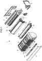
- FIG. 1 is an exploded perspective view of an air conditioner according to the present embodiment.
- FIG. 2 is a side view of a main body unit and a heat-exchanger bracket in the air conditioner according to the present embodiment.
- FIG. 3 is a side view of the main body unit in the air conditioner according to the present embodiment.
- FIG. 4 is a partially-enlarged front view of the main body unit in the air conditioner according to the present embodiment.
- FIG. 5 is a side view of the heat-exchanger bracket in the air conditioner according to the present embodiment.
- FIG. 6 is a partially-enlarged perspective view of the heat-exchanger bracket in the air conditioner according to the present embodiment.
- FIG. 7 is a partially-enlarged bottom view of the main body unit and the heat-exchanger bracket in the air conditioner according to the present embodiment.
- An air conditioner 1 illustrated in FIG. 1 is a wall-mounted type air conditioner.
- This air conditioner 1 includes an assembly of an installation plate 2 provided on a wall surface, a main body unit 3 attached to the installation plate 2, a blower (cross flow fan) 4 and a driving motor 5 thereof that are assembled to the main body unit 3, a heat exchanger 6 assembled to the main body unit 3, a refrigerant pipe 7 extended from one side of the heat exchanger 6 to a rear side, a control box 8 assembled to the main body unit 3, an outlet assembly 9 assembled to the main body unit 3, a front cover 10 assembled to the main body unit 3 in such a manner as to cover a front surface, an upper/lower surface, and a right/left surface of each device assembled to the main body unit 3, an air filter 11A and a cleaning mechanism 11B thereof that are assembled to the front cover 10, a front panel 12 attached to the front cover 10 in such a manner as to cover a front surface thereof, and the like.
- the main body unit 3 is placed on a rear side of the air conditioner 1 and is attached to the installation plate 2, which is provided on a wall surface, to support installation of the air conditioner 1.
- a main-body drain pan 3A arranged on a lower side of a rear side of the heat exchanger 6, which is bent and formed in a ⁇ shape (i.e. a reversed V shape), is formed.
- the cross flow fan 4 includes a cylindrical impeller provided horizontally along an air channel of the main body unit 3 and is rotatably supported by the main body unit 3 via the driving motor 5.
- the heat exchanger 6 is a fin-and-tube heat exchanger that is attached on a front side of the main body unit 3 and that is bent and formed in a ⁇ shape (i.e. a reversed V shape), and is provided in such a manner as to cover an upper surface and a front surface of the cross flow fan 4. From one side of the heat exchanger 6, the refrigerant pipe 7 for circulating a refrigerant is extended to a rear side. On the other side of this heat exchanger 6, a heat-exchanger bracket (bracket) 6A fixed to the main body unit 3 is provided.
- the air outlet assembly 9 in which a water-discharge drain pan 13, a stabilizer 14 to form an air channel of the cross flow fan 4, an outlet 15 to which a louver, a flap, and the like for wind direction adjustment are assembled are provided can be assembled.
- a drain hose 13A to drain water accumulated therein is attached to the water-discharge drain pan 13, a drain hose 13A to drain water accumulated therein is attached.
- the control box 8 is assembled to a right side portion of the main body unit 3 and controls an operation of the air conditioner 1 in accordance with a command from a remote controller.
- the front cover 10 covers a front surface, an upper/lower surface, and a right/left surface of each of the above devices assembled to the main body unit 3, a suction grille 16 to suck indoor air being formed on an upper surface and a front surface thereof.
- the air filter 11A to collect dust in the indoor air sucked through the suction grille 16
- the cleaning mechanism 11B to remove the dust, which is collected by the air filter 11A, from a filter surface and to automatically clean the air filter 11A are assembled.
- the front panel 12 is assembled to a front surface of the suction grille 16 in such a manner as to be openable/closable with an upper portion as a fulcrum.
- the main body unit 3 to which the cross flow fan 4 is attached and the heat-exchanger bracket 6A on the side portion of the heat exchanger 6 are fixed to each other with two screws 21.
- a screw tightening portion 3a into which the screw 21 is screwed is formed in the main body unit 3.
- a screw receiving portion 6Aa to support a head portion of the screw 21 is formed in the heat-exchanger bracket 6A.
- a side of the installation plate 2 on a wall side is a rear side and a side of the front panel 12 facing this is a front side in the wall-assembled type air conditioner 1. It is assumed that an upper side and a lower side in a front view are an upper side and a lower side and that an inner side and an outer side in the following express an inner side and an outer side of a housing of the air conditioner 1.
- the housing of the air conditioner 1 (also referred to as air conditioner housing) is in a form in which the above-described main body unit 3 and heat-exchanger bracket 6A are joined to each other, a side on which the heat exchanger 6 is arranged being the inner side and a side on which a gutter 3d (described later) is provided being the outer side.
- a fit-stepped portion 22 is provided at a joint end at which the main body unit 3 and the heat-exchanger bracket 6A are joined to each other in the vicinity of the screw receiving portion 6Aa and the screw tightening portion 3a.
- the fit-stepped portion 22 includes a stepped portion including a projection 6Ab and an edge 6Aba, from which the projection 6Ab is projected, on a side of the heat-exchanger bracket 6A and a stepped portion including a projection 3b and an edge 3ba, from which the projection 3b is projected, on a side of the main body unit 3.
- the projection 6Ab is formed, on an outer side of the edge 6Aba, in a manner projected to the side of the main body unit 3 joined to the heat-exchanger bracket 6A as illustrated in FIG. 6 and FIG. 7 .
- the projection 3b is formed, on an inner side of the edge 3ba, in a manner projected to the side of the heat-exchanger bracket 6A joined to the main body unit 3 as illustrated in FIG. 4 and FIG. 7 .
- This fit-stepped portion 22 is a portion where the side of the heat-exchanger bracket 6A and the side of the main body unit 3 are engaged with each other in joining of the main body unit 3 and the heat-exchanger bracket 6A. More specifically, as illustrated in FIG. 2 , FIG. 4 , and FIG.
- the projection 6Ab on the side of the heat-exchanger bracket 6A which projection is arranged on an outer side of the projection 3b on the side of the main body unit 3 and a leading end of which projection faces the edge 3ba on the side of the main body unit 3, and the projection 3b on the side of the main body unit 3, which projection is arranged in an inner side of the projection 6Ab on the side of the heat-exchanger bracket 6A and a leading end of which projection faces the edge 6Aba on the side of the heat-exchanger bracket 6A, are engaged with each other.
- the fit-stepped portion 22 has a spigot joint structure in which a recessed portion and a projected portion are engaged with each other with the side of the heat-exchanger bracket 6A being the outer side and the side of the main body unit 3 being the inner side.
- a projection rib 6Ac is formed in the heat-exchanger bracket 6A at the joint end at which the main body unit 3 and the heat-exchanger bracket 6A are joined to each other in the vicinity of the screw receiving portion 6Aa and the screw tightening portion 3a.
- the projection rib 6Ac is formed in such a manner as to be projected to a rear side (side of main body unit 3) of the heat-exchanger bracket 6A and is arranged along a wall surface 3c facing the outer side of the main body unit 3 in joining of the main body unit 3 and the heat-exchanger bracket 6A, as illustrated in FIG. 4 . Also, as illustrated in FIG.
- a reinforcement rib 6Aca which is provided in an elongated manner at a center on the opposite side of the side along the wall surface 3c of the main body unit 3, is provided in the projection rib 6Ac.
- the projection rib 6Ac has a T shape (i.e. a flat base from the middle of which extends a straight rib) as a whole and is reinforced.
- the reinforcement rib 6Aca may be provided in an elongated manner on a side portion of the projection rib 6Ac and may reinforce the projection rib 6Ac in an L shape as a whole (i.e.
- the reinforcement rib 6Aca may be provided in an elongated manner on both side portions of the projection rib 6Ac and may reinforce the projection rib 6Ac in a U shape as a whole.
- the gutter 3d connected to the main-body drain pan 3A is provided on a side portion of the main body unit 3 which portion is joined to the heat-exchanger bracket 6A.
- a drain outlet 3da toward the water-discharge drain pan 13 provided in the outlet assembly 9 assembled to the main body unit 3 is provided and water is sent to the water-discharge drain pan 13.
- this gutter 3d is provided in the vicinity of the screw tightening portion 3a, and the projection 3b and the edge 3ba on the side of the main body unit 3 which are the fit-stepped portion 22 are provided in a part thereof.
- the main body unit 3 and the heat-exchanger bracket 6A are joined to each other with the screw 21 in the vicinity of the gutter 3d, and the main body unit 3 and the heat-exchanger bracket 6A are engaged with and fit to each other in a part thereof by the fit-stepped portion 22.
- the projection rib 6Ac provided in the heat-exchanger bracket 6A is arranged along the wall surface 3c, which faces the outer side of the main body unit 3, in an inner portion of the gutter 3d. In this configuration, as illustrated in FIG. 4 , the projection rib 6Ac is provided at an upper position in the inner portion of the gutter 3d.
- the air conditioner 1 of the present embodiment includes the main body unit 3, to which the cross flow fan (blower) 4 is attached, and the heat-exchanger bracket 6A fixed to the heat exchanger 6 and attached to the main body unit 3. Also, the screw receiving portion 6Aa that is provided in such a manner as to be projected to an outer side of the heat-exchanger bracket 6A and that supports a head portion of the screw 21, the screw tightening portion 3a which is provided in the main body unit 3 and into which the screw 21 is screwed, and the fit-stepped portion 22 which is provided at a joint end on an inner side of a position where the screw receiving portion 6Aa and the screw tightening portion 3a are joined to each other with the screw 21 and in which engagement is made with a side of the heat-exchanger bracket 6A as an outer side in the air conditioner housing and a side of the main body unit 3 as an inner side in the air conditioner housing are included.
- the projection rib 6Ac arranged along the wall surface 3c, which faces the outer side of the main body unit 3, in a manner projected from the heat-exchanger bracket 6A is further included at the joint end.
- the reinforcement rib 6Aca is provided in the projection rib 6Ac.
- the projection rib 6Ac is preferably provided at an upper position in an inner portion of the gutter 3d connected to the main-body drain pan 3A provided in the main body unit 3.
- this air conditioner 1 it is possible to prevent water from being sucked in a gap between the projection rib 6Ac and the wall surface 3c of the main body unit 3 since the projection rib 6Ac is away from water flowing in the gutter 3d. Note that when the projection rib 6Ac is arranged in the inner portion of the gutter 3d, a design change to newly provide a portion, into which the projection rib 6Ac is inserted, on the side of the main body unit 3 is not necessary.
- the fit-stepped portion 22 is preferably provided in the gutter 3d connected to the main-body drain pan 3A provided in the main body unit 3.
- this air conditioner 1 since deformation of the heat-exchanger bracket 6A in a manner inclined to an outer side with respect to the main body unit 3 is controlled at a position of the gutter 3d, it is possible to control generation of a gap in the gutter 3d between the heat-exchanger bracket 6A and the main body unit 3 and to prevent a situation in which water flowing in the gutter 3d is sucked into an inner side of the main body unit 3 and scattered by the cross flow fan 4.
Landscapes
- Engineering & Computer Science (AREA)
- Chemical & Material Sciences (AREA)
- Combustion & Propulsion (AREA)
- Mechanical Engineering (AREA)
- General Engineering & Computer Science (AREA)
- Air Filters, Heat-Exchange Apparatuses, And Housings Of Air-Conditioning Units (AREA)
Abstract
Description
- The present invention relates to an air conditioner.
-
Patent Literature 1 discloses a conventional air conditioner including a main body unit (base main body) to which a heat exchanger, a blower, and the like are assembled. - In such an air conditioner, a bracket, which is provided in a side portion of the heat exchanger, and the main body unit are fastened with a screw, whereby the heat exchanger and the main body unit are joined to each other.
- Patent Literature 1:
Japanese Laid-open Patent Publication No. 2013-124855 A - In the above-described joining of a bracket of a heat exchanger and a main body unit with a screw, there is a case where the bracket deforms when the screw is tightened too strongly. When the bracket deforms, a clearance between a blower assembled to the main body unit and the bracket becomes narrow. To make matters worse, there is a case where the blower comes into contact with the bracket.
- The present invention is to solve the above-described problem and is to provide an air conditioner capable of preventing deformation of a bracket of a heat exchanger in joining of the heat exchanger and a main body unit.
- In one embodiment, an air conditioner including a main body unit to which a blower is attached, and a bracket that is fixed to a heat exchanger and that is attached to the main body unit includes a screw receiving portion that is provided in a manner projected to an outer side of the bracket and that supports a head portion of a screw, a screw tightening portion which is provided in the main body unit and into which the screw is screwed, and a fit-stepped portion which is provided at a joint end on an inner side of a position where the screw receiving portion and the screw tightening portion are joined to each other with the screw and in which engagement is made with a side of the bracket as an outer side in an air conditioner housing and a side of the main body unit as an inner side in the air conditioner housing.
- According to this air conditioner, when a screw receiving portion and a screw tightening portion are joined with a screw, even in a case where a bracket is about to deform in a manner inclined to an outer side with respect to a main body unit due to a tightening degree of the screw, the deformation is controlled since engagement in a fit-stepped portion is made with a side of the bracket as an outer side and a side of the main body unit as an inner side. Thus, it is possible to prevent deformation of a bracket in joining of a heat exchanger and a main body unit.
- The air conditioner of one embodiment further includes a projection rib that is arranged at the joint end along a wall surface, which faces an outer side of the main body unit, in a manner projected from the bracket.
- According to this air conditioner, deformation of a bracket in a manner inclined to an outer side with respect to a main body unit due to a tightening degree of a screw is further controlled since a projection rib is included. Thus, it is possible to notably acquire an effect of preventing deformation of a bracket in joining of a heat exchanger and a main body unit.
- In the air conditioner of one embodiment, a reinforcement rib is provided in the projection rib.
- According to this air conditioner, strength of controlling deformation of a bracket in a manner inclined to an outer side with respect to a main body unit is improved by reinforcement of a projection rib with a reinforcement rib. Thus, it is possible to notably acquire an effect of preventing deformation of a bracket in joining of a heat exchanger and a main body unit.
- In the air conditioner of one embodiment, the projection rib is provided at an upper position in an inner portion of a gutter connected to a main-body drain pan provided in the main body unit.
- According to this air conditioner, it is possible to prevent water from being sucked in a gap between the projection rib and the wall surface of the main body unit since the projection rib is away from water flowing in the gutter.
- In the air conditioner of one embodiment, the fit-stepped portion is provided in a gutter connected to a main-body drain pan provided in the main body unit.
- According to this air conditioner, since deformation of a bracket in a manner inclined to an outer side with respect to a main body unit is controlled at a position of a gutter, it is possible to control generation of a gap in the gutter between the bracket and the main body unit. Thus, it is possible to prevent water flowing in the gutter from being sucked into an inner side of the main body unit and being scattered by a blower. Advantageous Effects of Invention
- According to the present invention, it is possible to prevent deformation of a bracket of a heat exchanger in joining of the heat exchanger and a main body unit.
-
-
FIG. 1 is an exploded perspective view of an air conditioner according to an embodiment of the present invention. -
FIG. 2 is a side view of a main body unit and a heat-exchanger bracket in the air conditioner according to the embodiment of the present invention. -
FIG. 3 is a side view of the main body unit in the air conditioner according to the embodiment of the present invention. -
FIG. 4 is a partially-enlarged front view of the main body unit in the air conditioner according to the embodiment of the present invention. -
FIG. 5 is a side view of the heat-exchanger bracket in the air conditioner according to the embodiment of the present invention. -
FIG. 6 is a partially-enlarged perspective view of the heat-exchanger bracket in the air conditioner according to the embodiment of the present invention. -
FIG. 7 is a partially-enlarged bottom view of the main body unit and the heat-exchanger bracket in the air conditioner according to the embodiment of the present invention. - In the following, an embodiment according to the present invention will be described in detail with reference to the drawings. Note that this invention is not limited by this embodiment. Also, one can understand that some components as described in reference to the following embodiment can be easily replaced by those skilled in the art by components that are substantially the same.
-
FIG. 1 is an exploded perspective view of an air conditioner according to the present embodiment.FIG. 2 is a side view of a main body unit and a heat-exchanger bracket in the air conditioner according to the present embodiment.FIG. 3 is a side view of the main body unit in the air conditioner according to the present embodiment.FIG. 4 is a partially-enlarged front view of the main body unit in the air conditioner according to the present embodiment.FIG. 5 is a side view of the heat-exchanger bracket in the air conditioner according to the present embodiment.FIG. 6 is a partially-enlarged perspective view of the heat-exchanger bracket in the air conditioner according to the present embodiment.FIG. 7 is a partially-enlarged bottom view of the main body unit and the heat-exchanger bracket in the air conditioner according to the present embodiment. - An
air conditioner 1 illustrated inFIG. 1 is a wall-mounted type air conditioner. Thisair conditioner 1 includes an assembly of aninstallation plate 2 provided on a wall surface, amain body unit 3 attached to theinstallation plate 2, a blower (cross flow fan) 4 and adriving motor 5 thereof that are assembled to themain body unit 3, aheat exchanger 6 assembled to themain body unit 3, arefrigerant pipe 7 extended from one side of theheat exchanger 6 to a rear side, acontrol box 8 assembled to themain body unit 3, anoutlet assembly 9 assembled to themain body unit 3, afront cover 10 assembled to themain body unit 3 in such a manner as to cover a front surface, an upper/lower surface, and a right/left surface of each device assembled to themain body unit 3, anair filter 11A and acleaning mechanism 11B thereof that are assembled to thefront cover 10, afront panel 12 attached to thefront cover 10 in such a manner as to cover a front surface thereof, and the like. - The
main body unit 3 is placed on a rear side of theair conditioner 1 and is attached to theinstallation plate 2, which is provided on a wall surface, to support installation of theair conditioner 1. In themain body unit 3, a main-body drain pan 3A arranged on a lower side of a rear side of theheat exchanger 6, which is bent and formed in a Λ shape (i.e. a reversed V shape), is formed. Thecross flow fan 4 includes a cylindrical impeller provided horizontally along an air channel of themain body unit 3 and is rotatably supported by themain body unit 3 via thedriving motor 5. - The
heat exchanger 6 is a fin-and-tube heat exchanger that is attached on a front side of themain body unit 3 and that is bent and formed in a Λ shape (i.e. a reversed V shape), and is provided in such a manner as to cover an upper surface and a front surface of thecross flow fan 4. From one side of theheat exchanger 6, therefrigerant pipe 7 for circulating a refrigerant is extended to a rear side. On the other side of thisheat exchanger 6, a heat-exchanger bracket (bracket) 6A fixed to themain body unit 3 is provided. - Also, to a lower part on a front side of the
heat exchanger 6, theair outlet assembly 9 in which a water-discharge drain pan 13, astabilizer 14 to form an air channel of thecross flow fan 4, anoutlet 15 to which a louver, a flap, and the like for wind direction adjustment are assembled are provided can be assembled. To the water-discharge drain pan 13, adrain hose 13A to drain water accumulated therein is attached. - The
control box 8 is assembled to a right side portion of themain body unit 3 and controls an operation of theair conditioner 1 in accordance with a command from a remote controller. Thefront cover 10 covers a front surface, an upper/lower surface, and a right/left surface of each of the above devices assembled to themain body unit 3, asuction grille 16 to suck indoor air being formed on an upper surface and a front surface thereof. To thesuction grille 16, theair filter 11A to collect dust in the indoor air sucked through thesuction grille 16, and thecleaning mechanism 11B to remove the dust, which is collected by theair filter 11A, from a filter surface and to automatically clean theair filter 11A are assembled. Also, thefront panel 12 is assembled to a front surface of thesuction grille 16 in such a manner as to be openable/closable with an upper portion as a fulcrum. - As illustrated in
FIG. 2 , themain body unit 3 to which thecross flow fan 4 is attached and the heat-exchanger bracket 6A on the side portion of theheat exchanger 6 are fixed to each other with twoscrews 21. Here, as illustrated inFIG. 2 to FIG. 4 and inFIG. 7 , in a portion fixed with thescrew 21 in the vicinity of arotary shaft 4a of thecross flow fan 4, ascrew tightening portion 3a into which thescrew 21 is screwed is formed in themain body unit 3. On the other hand, as illustrated inFIG. 2 , andFIG. 5 toFIG. 7 , a screw receiving portion 6Aa to support a head portion of thescrew 21 is formed in the heat-exchanger bracket 6A. Thus, when thescrew 21 is screwed into thescrew tightening portion 3a via the screw receiving portion 6Aa, the screw receiving portion 6Aa and thescrew tightening portion 3a are abutted to each other and themain body unit 3 and the heat-exchanger bracket 6A are joined to each other. - As illustrated in
FIG. 2 to FIG. 7 , it is assumed that a side of theinstallation plate 2 on a wall side is a rear side and a side of thefront panel 12 facing this is a front side in the wall-assembledtype air conditioner 1. It is assumed that an upper side and a lower side in a front view are an upper side and a lower side and that an inner side and an outer side in the following express an inner side and an outer side of a housing of theair conditioner 1. Also, the housing of the air conditioner 1 (also referred to as air conditioner housing) is in a form in which the above-describedmain body unit 3 and heat-exchanger bracket 6A are joined to each other, a side on which theheat exchanger 6 is arranged being the inner side and a side on which a gutter 3d (described later) is provided being the outer side. - Also, as illustrated in
FIG. 2 to FIG. 7 , a fit-steppedportion 22 is provided at a joint end at which themain body unit 3 and the heat-exchanger bracket 6A are joined to each other in the vicinity of the screw receiving portion 6Aa and thescrew tightening portion 3a. The fit-steppedportion 22 includes a stepped portion including a projection 6Ab and an edge 6Aba, from which the projection 6Ab is projected, on a side of the heat-exchanger bracket 6A and a stepped portion including aprojection 3b and an edge 3ba, from which theprojection 3b is projected, on a side of themain body unit 3. In the stepped portion on the side of the heat-exchanger bracket 6A, the projection 6Ab is formed, on an outer side of the edge 6Aba, in a manner projected to the side of themain body unit 3 joined to the heat-exchanger bracket 6A as illustrated inFIG. 6 andFIG. 7 . In the stepped portion on the side of themain body unit 3, theprojection 3b is formed, on an inner side of the edge 3ba, in a manner projected to the side of the heat-exchanger bracket 6A joined to themain body unit 3 as illustrated inFIG. 4 andFIG. 7 . This fit-steppedportion 22 is a portion where the side of the heat-exchanger bracket 6A and the side of themain body unit 3 are engaged with each other in joining of themain body unit 3 and the heat-exchanger bracket 6A. More specifically, as illustrated inFIG. 2 ,FIG. 4 , andFIG. 7 , in the fit-steppedportion 22, the projection 6Ab on the side of the heat-exchanger bracket 6A, which projection is arranged on an outer side of theprojection 3b on the side of themain body unit 3 and a leading end of which projection faces the edge 3ba on the side of themain body unit 3, and theprojection 3b on the side of themain body unit 3, which projection is arranged in an inner side of the projection 6Ab on the side of the heat-exchanger bracket 6A and a leading end of which projection faces the edge 6Aba on the side of the heat-exchanger bracket 6A, are engaged with each other. That is, the fit-steppedportion 22 has a spigot joint structure in which a recessed portion and a projected portion are engaged with each other with the side of the heat-exchanger bracket 6A being the outer side and the side of themain body unit 3 being the inner side. - Also, as illustrated in
FIG. 2 , andFIG. 4 toFIG. 6 , a projection rib 6Ac is formed in the heat-exchanger bracket 6A at the joint end at which themain body unit 3 and the heat-exchanger bracket 6A are joined to each other in the vicinity of the screw receiving portion 6Aa and thescrew tightening portion 3a. The projection rib 6Ac is formed in such a manner as to be projected to a rear side (side of main body unit 3) of the heat-exchanger bracket 6A and is arranged along awall surface 3c facing the outer side of themain body unit 3 in joining of themain body unit 3 and the heat-exchanger bracket 6A, as illustrated inFIG. 4 . Also, as illustrated inFIG. 4 , a reinforcement rib 6Aca, which is provided in an elongated manner at a center on the opposite side of the side along thewall surface 3c of themain body unit 3, is provided in the projection rib 6Ac. As illustrated inFIG. 4 andFIG. 6 , since the reinforcement rib 6Aca is included, the projection rib 6Ac has a T shape (i.e. a flat base from the middle of which extends a straight rib) as a whole and is reinforced. Note that although not illustrated clearly in the drawings, the reinforcement rib 6Aca may be provided in an elongated manner on a side portion of the projection rib 6Ac and may reinforce the projection rib 6Ac in an L shape as a whole (i.e. a flat base from an end of which extends a straight rib). Alternatively, the reinforcement rib 6Aca may be provided in an elongated manner on both side portions of the projection rib 6Ac and may reinforce the projection rib 6Ac in a U shape as a whole. - Incidentally, on a side portion of the
main body unit 3 which portion is joined to the heat-exchanger bracket 6A, the gutter 3d connected to the main-body drain pan 3A is provided. In the gutter 3d, a drain outlet 3da toward the water-discharge drain pan 13 provided in theoutlet assembly 9 assembled to themain body unit 3 is provided and water is sent to the water-discharge drain pan 13. As illustrated inFIG. 4 , this gutter 3d is provided in the vicinity of thescrew tightening portion 3a, and theprojection 3b and the edge 3ba on the side of themain body unit 3 which are the fit-steppedportion 22 are provided in a part thereof. That is, themain body unit 3 and the heat-exchanger bracket 6A are joined to each other with thescrew 21 in the vicinity of the gutter 3d, and themain body unit 3 and the heat-exchanger bracket 6A are engaged with and fit to each other in a part thereof by the fit-steppedportion 22. Also, the projection rib 6Ac provided in the heat-exchanger bracket 6A is arranged along thewall surface 3c, which faces the outer side of themain body unit 3, in an inner portion of the gutter 3d. In this configuration, as illustrated inFIG. 4 , the projection rib 6Ac is provided at an upper position in the inner portion of the gutter 3d. - As described above, the
air conditioner 1 of the present embodiment includes themain body unit 3, to which the cross flow fan (blower) 4 is attached, and the heat-exchanger bracket 6A fixed to theheat exchanger 6 and attached to themain body unit 3. Also, the screw receiving portion 6Aa that is provided in such a manner as to be projected to an outer side of the heat-exchanger bracket 6A and that supports a head portion of thescrew 21, thescrew tightening portion 3a which is provided in themain body unit 3 and into which thescrew 21 is screwed, and the fit-steppedportion 22 which is provided at a joint end on an inner side of a position where the screw receiving portion 6Aa and thescrew tightening portion 3a are joined to each other with thescrew 21 and in which engagement is made with a side of the heat-exchanger bracket 6A as an outer side in the air conditioner housing and a side of themain body unit 3 as an inner side in the air conditioner housing are included. - According to this
air conditioner 1, when the screw receiving portion 6Aa and thescrew tightening portion 3a are joined to each other with thescrew 21, even in a case where the heat-exchanger bracket 6A is about to deform in a manner inclined to the outer side with respect to themain body unit 3 due to a tightening degree of thescrew 21, the deformation is controlled since engagement is made in the fit-steppedportion 22 with the side of the heat-exchanger bracket 6A as an outer side and the side of themain body unit 3 as an inner side. Thus, it is possible to prevent deformation of the heat-exchanger bracket 6A in joining of theheat exchanger 6 and themain body unit 3. - Also, in the
air conditioner 1 of the present embodiment, it is preferable that the projection rib 6Ac arranged along thewall surface 3c, which faces the outer side of themain body unit 3, in a manner projected from the heat-exchanger bracket 6A is further included at the joint end. - According to this
air conditioner 1, deformation of the heat-exchanger bracket 6A in a manner inclined to the outer side with respect to themain body unit 3 due to a tightening degree of thescrew 21 is further controlled since the projection rib 6Ac is included. Thus, it is possible to notably acquire an effect of preventing deformation of the heat-exchanger bracket 6A in joining of theheat exchanger 6 and themain body unit 3. - Also, in the
air conditioner 1 of the present embodiment, it is preferable that the reinforcement rib 6Aca is provided in the projection rib 6Ac. - According to this
air conditioner 1, strength of controlling deformation of the heat-exchanger bracket 6A in a manner inclined to the outer side with respect to themain body unit 3 is improved by reinforcement of the projection rib 6Ac with the reinforcement rib 6Aca. Thus, it is possible to notably acquire an effect of preventing deformation of the heat-exchanger bracket 6A in joining of theheat exchanger 6 and themain body unit 3. - Also, in the
air conditioner 1 of the present embodiment, the projection rib 6Ac is preferably provided at an upper position in an inner portion of the gutter 3d connected to the main-body drain pan 3A provided in themain body unit 3. - According to this
air conditioner 1, it is possible to prevent water from being sucked in a gap between the projection rib 6Ac and thewall surface 3c of themain body unit 3 since the projection rib 6Ac is away from water flowing in the gutter 3d. Note that when the projection rib 6Ac is arranged in the inner portion of the gutter 3d, a design change to newly provide a portion, into which the projection rib 6Ac is inserted, on the side of themain body unit 3 is not necessary. - Also, in the
air conditioner 1 of the present embodiment, the fit-steppedportion 22 is preferably provided in the gutter 3d connected to the main-body drain pan 3A provided in themain body unit 3. - According to this
air conditioner 1, since deformation of the heat-exchanger bracket 6A in a manner inclined to an outer side with respect to themain body unit 3 is controlled at a position of the gutter 3d, it is possible to control generation of a gap in the gutter 3d between the heat-exchanger bracket 6A and themain body unit 3 and to prevent a situation in which water flowing in the gutter 3d is sucked into an inner side of themain body unit 3 and scattered by thecross flow fan 4. -
- 1
- AIR CONDITIONER
- 3
- MAIN BODY UNIT
- 3a
- SCREW TIGHTENING PORTION
- 3b
- PROJECTION
- 3ba
- EDGE
- 3c
- WALL SURFACE
- 3d
- GUTTER
- 3A
- MAIN-BODY DRAIN PAN
- 4
- CROSS FLOW FAN (BLOWER)
- 6
- HEAT EXCHANGER
- 6A
- HEAT-EXCHANGER BRACKET
- 6Aa
- SCREW RECEIVING PORTION
- 6Ab
- PROJECTION
- 6Aba
- EDGE
- 6Ac
- PROJECTION RIB
- 6Aca
- REINFORCEMENT RIB
- 21
- SCREW
- 22
- FIT-STEPPED PORTION
Claims (5)
- An air conditioner (1) including a main body unit (3) to which a blower (4) is attached, and a bracket (6A) that is fixed to a heat exchanger (6) and that is attached to the main body unit (3), the air conditioner (1) comprising:a screw receiving portion (6Aa) that is provided in a manner projected to an outer side of the bracket (6A) and that supports a head portion of a screw (21);a screw tightening portion (3a) which is provided in the main body unit (3) and into which the screw (21) is screwed; anda fit-stepped portion (22) which is provided at a joint end on an inner side of a position where the screw receiving portion (6Aa) and the screw tightening portion (3a) are joined to each other with the screw (21) and in which engagement is made with a side of the bracket (6A) as an outer side in an air conditioner housing and a side of the main body unit (3) as an inner side in the air conditioner housing.
- The air conditioner (1) according to claim 1, further comprising a projection rib (6Ac) that is arranged at the joint end along a wall surface (3c), which faces an outer side of the main body unit (3), in a manner projected from the bracket (6A).
- The air conditioner (1) according to claim 2, wherein a reinforcement rib (6Aca) is provided in the projection rib (6Ac).
- The air conditioner (1) according to claim 2 or 3, wherein the projection rib (6Ac) is provided at an upper position in an inner portion of a gutter (3d) connected to a main-body drain pan (3A) provided in the main body unit (3).
- The air conditioner (1) according to any one of claims 1 to 4, wherein the fit-stepped portion (22) is provided in a gutter (3d) connected to a main-body drain pan (3A) provided in the main body unit (3).
Applications Claiming Priority (1)
| Application Number | Priority Date | Filing Date | Title |
|---|---|---|---|
| JP2016008741A JP2017129309A (en) | 2016-01-20 | 2016-01-20 | Air conditioner |
Publications (1)
| Publication Number | Publication Date |
|---|---|
| EP3196566A1 true EP3196566A1 (en) | 2017-07-26 |
Family
ID=57850986
Family Applications (1)
| Application Number | Title | Priority Date | Filing Date |
|---|---|---|---|
| EP17152198.2A Withdrawn EP3196566A1 (en) | 2016-01-20 | 2017-01-19 | Air conditioner |
Country Status (3)
| Country | Link |
|---|---|
| EP (1) | EP3196566A1 (en) |
| JP (1) | JP2017129309A (en) |
| AU (1) | AU2017200364B2 (en) |
Cited By (2)
| Publication number | Priority date | Publication date | Assignee | Title |
|---|---|---|---|---|
| WO2020155676A1 (en) * | 2019-01-31 | 2020-08-06 | 广东美的制冷设备有限公司 | Wall-mounted indoor air conditioner unit |
| CN115095982A (en) * | 2022-06-17 | 2022-09-23 | 宁波奥克斯电气股份有限公司 | Evaporator upper bracket, air conditioner indoor unit and air conditioner |
Citations (6)
| Publication number | Priority date | Publication date | Assignee | Title |
|---|---|---|---|---|
| US5205472A (en) * | 1991-01-18 | 1993-04-27 | Sullivan John T | Fan coil unit |
| US5468186A (en) * | 1994-03-09 | 1995-11-21 | Carrier Corporation | Snap-on air deflectors for air conditioner |
| EP1607692A1 (en) * | 2004-06-15 | 2005-12-21 | Lg Electronics Inc. | Air conditioner |
| US20100212861A1 (en) * | 2009-02-24 | 2010-08-26 | Setsu Michio | Air conditioner |
| JP2013124855A (en) | 2011-12-16 | 2013-06-24 | Mitsubishi Heavy Ind Ltd | Wall-hanging air conditioner |
| EP2722609A1 (en) * | 2011-06-20 | 2014-04-23 | Sanyo Electric Co., Ltd | Built-in type air conditioning device |
Family Cites Families (4)
| Publication number | Priority date | Publication date | Assignee | Title |
|---|---|---|---|---|
| JPS5717217Y2 (en) * | 1977-12-08 | 1982-04-10 | ||
| JP3143305B2 (en) * | 1993-12-28 | 2001-03-07 | 三洋電機株式会社 | Air conditioner |
| JP5174530B2 (en) * | 2008-05-16 | 2013-04-03 | 三菱電機株式会社 | Air conditioner |
| JP2015161432A (en) * | 2014-02-26 | 2015-09-07 | 三菱電機株式会社 | air conditioner indoor unit |
-
2016
- 2016-01-20 JP JP2016008741A patent/JP2017129309A/en active Pending
-
2017
- 2017-01-19 AU AU2017200364A patent/AU2017200364B2/en active Active
- 2017-01-19 EP EP17152198.2A patent/EP3196566A1/en not_active Withdrawn
Patent Citations (6)
| Publication number | Priority date | Publication date | Assignee | Title |
|---|---|---|---|---|
| US5205472A (en) * | 1991-01-18 | 1993-04-27 | Sullivan John T | Fan coil unit |
| US5468186A (en) * | 1994-03-09 | 1995-11-21 | Carrier Corporation | Snap-on air deflectors for air conditioner |
| EP1607692A1 (en) * | 2004-06-15 | 2005-12-21 | Lg Electronics Inc. | Air conditioner |
| US20100212861A1 (en) * | 2009-02-24 | 2010-08-26 | Setsu Michio | Air conditioner |
| EP2722609A1 (en) * | 2011-06-20 | 2014-04-23 | Sanyo Electric Co., Ltd | Built-in type air conditioning device |
| JP2013124855A (en) | 2011-12-16 | 2013-06-24 | Mitsubishi Heavy Ind Ltd | Wall-hanging air conditioner |
Cited By (2)
| Publication number | Priority date | Publication date | Assignee | Title |
|---|---|---|---|---|
| WO2020155676A1 (en) * | 2019-01-31 | 2020-08-06 | 广东美的制冷设备有限公司 | Wall-mounted indoor air conditioner unit |
| CN115095982A (en) * | 2022-06-17 | 2022-09-23 | 宁波奥克斯电气股份有限公司 | Evaporator upper bracket, air conditioner indoor unit and air conditioner |
Also Published As
| Publication number | Publication date |
|---|---|
| AU2017200364A1 (en) | 2017-08-03 |
| JP2017129309A (en) | 2017-07-27 |
| AU2017200364B2 (en) | 2018-03-29 |
Similar Documents
| Publication | Publication Date | Title |
|---|---|---|
| EP2299192B1 (en) | Indoor unit of air conditioner | |
| EP2604943A2 (en) | Wall-hanging air conditioner | |
| US20180195790A1 (en) | Indoor unit for air conditioner | |
| JP6157407B2 (en) | Air conditioner wind direction adjusting device and air conditioner | |
| AU2017200364B2 (en) | Air conditioner | |
| JP5949752B2 (en) | Air conditioner | |
| JP6176562B2 (en) | Ceiling suspended air conditioner | |
| CN103429966A (en) | Air conditioner | |
| JP6160156B2 (en) | Air conditioning indoor unit | |
| KR20100051957A (en) | Indoor unit for air conditioning apparatus | |
| JP2012097930A (en) | Duct type air conditioner | |
| KR102361294B1 (en) | Indoor unit for air conditioner | |
| JP2017110834A (en) | Ceiling embedded type indoor unit | |
| JP2010048468A (en) | Air conditioner | |
| CN203785086U (en) | Built-in type air conditioner | |
| CN111263870B (en) | Air conditioner | |
| JPH0659722U (en) | Ceiling mounted air conditioner | |
| EP3184926A1 (en) | Air conditioner | |
| JP6145865B2 (en) | Ceiling suspended air conditioner | |
| JP5071600B2 (en) | Air conditioner | |
| JP4609436B2 (en) | Air conditioner | |
| JP2019135432A (en) | Louver, air conditioner, and assembly method of air conditioner | |
| JP2010048470A (en) | Air conditioner | |
| JP2005300153A (en) | Air conditioner and separate type air conditioner | |
| JP6296375B2 (en) | Ceiling suspended air conditioner |
Legal Events
| Date | Code | Title | Description |
|---|---|---|---|
| PUAI | Public reference made under article 153(3) epc to a published international application that has entered the european phase |
Free format text: ORIGINAL CODE: 0009012 |
|
| STAA | Information on the status of an ep patent application or granted ep patent |
Free format text: STATUS: REQUEST FOR EXAMINATION WAS MADE |
|
| 17P | Request for examination filed |
Effective date: 20170119 |
|
| AK | Designated contracting states |
Kind code of ref document: A1 Designated state(s): AL AT BE BG CH CY CZ DE DK EE ES FI FR GB GR HR HU IE IS IT LI LT LU LV MC MK MT NL NO PL PT RO RS SE SI SK SM TR |
|
| AX | Request for extension of the european patent |
Extension state: BA ME |
|
| GRAP | Despatch of communication of intention to grant a patent |
Free format text: ORIGINAL CODE: EPIDOSNIGR1 |
|
| STAA | Information on the status of an ep patent application or granted ep patent |
Free format text: STATUS: GRANT OF PATENT IS INTENDED |
|
| INTG | Intention to grant announced |
Effective date: 20191021 |
|
| STAA | Information on the status of an ep patent application or granted ep patent |
Free format text: STATUS: THE APPLICATION IS DEEMED TO BE WITHDRAWN |
|
| 18D | Application deemed to be withdrawn |
Effective date: 20200303 |