EP3196499A1 - Torque tube damping devices and assemblies - Google Patents
Torque tube damping devices and assemblies Download PDFInfo
- Publication number
- EP3196499A1 EP3196499A1 EP16204302.0A EP16204302A EP3196499A1 EP 3196499 A1 EP3196499 A1 EP 3196499A1 EP 16204302 A EP16204302 A EP 16204302A EP 3196499 A1 EP3196499 A1 EP 3196499A1
- Authority
- EP
- European Patent Office
- Prior art keywords
- torque tube
- various embodiments
- channel
- disposed
- barrel portion
- Prior art date
- Legal status (The legal status is an assumption and is not a legal conclusion. Google has not performed a legal analysis and makes no representation as to the accuracy of the status listed.)
- Granted
Links
Images


Classifications
-
- F—MECHANICAL ENGINEERING; LIGHTING; HEATING; WEAPONS; BLASTING
- F16—ENGINEERING ELEMENTS AND UNITS; GENERAL MEASURES FOR PRODUCING AND MAINTAINING EFFECTIVE FUNCTIONING OF MACHINES OR INSTALLATIONS; THERMAL INSULATION IN GENERAL
- F16D—COUPLINGS FOR TRANSMITTING ROTATION; CLUTCHES; BRAKES
- F16D65/00—Parts or details
- F16D65/0006—Noise or vibration control
-
- B—PERFORMING OPERATIONS; TRANSPORTING
- B64—AIRCRAFT; AVIATION; COSMONAUTICS
- B64C—AEROPLANES; HELICOPTERS
- B64C25/00—Alighting gear
- B64C25/32—Alighting gear characterised by elements which contact the ground or similar surface
- B64C25/42—Arrangement or adaptation of brakes
-
- B—PERFORMING OPERATIONS; TRANSPORTING
- B64—AIRCRAFT; AVIATION; COSMONAUTICS
- B64C—AEROPLANES; HELICOPTERS
- B64C25/00—Alighting gear
- B64C25/32—Alighting gear characterised by elements which contact the ground or similar surface
- B64C25/58—Arrangements or adaptations of shock-absorbers or springs
-
- F—MECHANICAL ENGINEERING; LIGHTING; HEATING; WEAPONS; BLASTING
- F16—ENGINEERING ELEMENTS AND UNITS; GENERAL MEASURES FOR PRODUCING AND MAINTAINING EFFECTIVE FUNCTIONING OF MACHINES OR INSTALLATIONS; THERMAL INSULATION IN GENERAL
- F16D—COUPLINGS FOR TRANSMITTING ROTATION; CLUTCHES; BRAKES
- F16D55/00—Brakes with substantially-radial braking surfaces pressed together in axial direction, e.g. disc brakes
- F16D55/24—Brakes with substantially-radial braking surfaces pressed together in axial direction, e.g. disc brakes with a plurality of axially-movable discs, lamellae, or pads, pressed from one side towards an axially-located member
- F16D55/26—Brakes with substantially-radial braking surfaces pressed together in axial direction, e.g. disc brakes with a plurality of axially-movable discs, lamellae, or pads, pressed from one side towards an axially-located member without self-tightening action
- F16D55/36—Brakes with a plurality of rotating discs all lying side by side
Definitions
- the present disclosure relates to torque tubes and torque tube assemblies, and more particularly, to vibration damping aircraft brake torque tubes and torque tube assemblies.
- Aircraft brake systems typically employ a series of rotors and stators that, when forced into contact with each other, help to stop the aircraft. Stators splined to a non-rotating torque tube are interspersed with rotors splined to the rotating wheel. Compression of the rotating rotors against the stationary stators causes torque to react through the stators to the torque tube, causing twisting and vibration of the torque tube.
- the present disclosure provides a torque tube comprising a barrel portion disposed between a flange and a back leg, the flange extending radially inward towards an axis of rotation and the back leg extending radially outward from the barrel portion.
- the torque tube further comprises a first spline disposed on an outer diameter of the barrel portion, a second spline disposed on an outer diameter of the barrel portion and substantially parallel to the first spline, and a channel defined by a channel wall and disposed in at least one of the barrel portion and the flange, the channel being configured to receive a sacrificial member.
- the torque tube may further comprise a torque tube foot disposed on an inner diameter of the barrel portion, the torque tube foot comprising at least one of a groove or an aperture configured to receive a sacrificial member.
- the channel wall may comprise an obtuse-angled edge. In various embodiments, the channel wall may comprise an acute-angled edge.
- the channel may be disposed in an outer diameter of the barrel portion. In various embodiments, the channel may extend in an axial direction at least partially between the flange and the back leg. In various embodiments, the channel may extend in a radial direction at least partially between the first spline and the second spline.
- the present disclosure provides a torque tube assembly comprising a torque tube having a barrel portion disposed between a flange and a back leg, the flange extending radially inward towards an axis of rotation and the back leg extending radially outward from the barrel portion.
- the torque tube assembly further comprises a sacrificial member disposed on at least one of the flange and a torque tube foot, the torque tube foot being disposed on an inner diameter of the barrel portion, wherein a friction face of the sacrificial member is in frictional contact with the inner diameter of the barrel portion.
- the sacrificial member may comprise a carbon composite material.
- the torque tube assembly may further comprise a rivet configured to couple the sacrificial member to at least one of the flange and the torque tube foot.
- the sacrificial member may be disposed on the flange and extends in an axial direction at least partially between the flange and the torque tube foot.
- the torque tube assembly may further comprise a channel defined by a channel wall and disposed in the flange, wherein sacrificial member is at least partially disposed in the channel.
- the channel wall may comprise an obtuse-angled edge.
- the channel wall may comprise an acute-angled edge.
- the sacrificial member may be disposed on the torque tube foot and extends in an axial direction at least partially between the torque tube foot and the flange.
- the present disclosure provides a torque tube assembly comprising a torque tube comprising a barrel portion disposed between a flange and a back leg, the back leg extending radially outward from the barrel portion, a first spline disposed on an outer diameter of the barrel portion, a second spline disposed on an outer diameter of the barrel portion and substantially parallel to the first spline, and a channel defined by a channel wall and disposed in an outer diameter of the barrel portion.
- the torque tube assembly further comprises a sacrificial member disposed in the channel, wherein a friction face of the sacrificial member is in frictional contact with the channel.
- the channel wall may comprise an obtuse-angled edge. In various embodiments, the channel wall may comprise an acute-angled edge. In various embodiments, the channel may extend in an axial direction at least partially between the flange and the back leg. In various embodiments, the channel may extend in a radial direction at least partially between the first spline and the second spline.
- any of the method or process descriptions may be executed in any order and are not necessarily limited to the order presented.
- any reference to singular includes plural embodiments, and any reference to more than one component or step may include a singular embodiment or step.
- any reference to attached, fixed, connected, or the like may include permanent, removable, temporary, partial, full, and/or any other possible attachment option.
- any reference to without contact (or similar phrases) may also include reduced contact or minimal contact.
- systems and methods may find particular use in connection with aircraft brake torque tubes.
- various aspects of the disclosed embodiments may be adapted for optimized performance with a variety of torque tubes and/or torque tube assemblies. As such, numerous applications of the present disclosure may be realized.
- a wheel and brake assembly 100 may comprise a wheel 102 at least partially surrounding a brake assembly.
- the brake assembly comprises a brake stack 120 oriented about axis of rotation 112.
- Brake stack 120 may comprise a plurality of alternating stators 126 and rotors 122.
- the brake assembly may further comprise one or more torque bars 108 configured to engage with rotors 122 as wheel 102, torque bars 108, and rotors 122 rotate about axis of rotation 112.
- stators 126 may be stationary and may be coupled to torque tube 128.
- torque tube 128 may be coupled to an axle sleeve and/or axle 104 via a bushing.
- torque tube 128 may comprise at least one spline 130 on its outer diameter.
- the at least one spline 130 may be configured to couple stators 126 to torque tube 128, thereby preventing rotation of stators 126.
- compression of rotating rotors 122 against stationary stators 126 may cause torque to react through stators and into torque tube 128.
- FIG. 1 provides a general understanding of portions of a wheel and brake assembly, and is not intended to limit the disclosure.
- a torque tube assembly 200a may comprise a torque tube 201a and a sacrificial member 250a.
- torque tube 201a may be oriented about an axis of rotation 112.
- the torque tube 201 a may comprise a barrel portion 210a disposed between a flange 202a and a back leg 204a.
- flange 202a may be disposed on a first axial end of torque tube 201 a and may extend radially inward from barrel portion 210a towards axis of rotation 112.
- back leg 204a may be disposed on a second axial end of torque tube 201 a and extend radially outward from barrel portion 210a.
- torque tube 201a may further comprise at least one spline 230 disposed on an outer diameter of barrel portion 210a.
- spline 230 may extend axially along the outer diameter of barrel portion 210a at least partially between flange 202a and back leg 204a.
- torque tube 201 a may comprise a plurality of splines disposed radially about the outer diameter of barrel portion 210a.
- each spline 230 of the plurality of splines may be disposed substantially parallel to the others.
- torque tube 201a may comprise a torque tube foot 260a configured to couple torque tube 201 a to wheel axle 104 (with momentary reference to FIG. 1 ).
- torque tube foot 260a may be disposed on, and extending circumferentially about, an inner diameter of barrel portion 210a.
- torque tube foot 260a may be disposed axially between flange 202a and back leg 204a.
- torque tube foot 260a may extend radially inward from barrel portion 210a.
- torque tube foot 260a and barrel portion 210a may be disposed relative to one another so as to define a circumferential groove 262a therebetween.
- circumferential groove 262a may be configured to receive a sacrificial member 250a.
- torque tube foot 260a may comprise at least one aperture 264a extending axially from a first axial end of torque tube foot 260a to a second axial end of torque tube foot 260a.
- aperture 264a may be configured to receive a sacrificial member 250a.
- torque tube 201 a may further comprise a channel 240.
- channel 240 may comprise a slot, channel, depression, or the like and may be configured to receive a sacrificial member 250a (described below).
- channel 240 may be disposed in flange 202a.
- channel 240 may be disposed in an inner diameter of barrel portion 210a.
- channel 240 may be defined by channel wall 242 and/or a channel base 244.
- channel wall 242 may define a depth of channel 240 extending radially outward into a surface of flange 202a and/or the inner diameter of barrel portion 210a.
- channel wall 242 may define a profile or shape of channel 240.
- channel wall 242 and channel base 244 may define a profile or shape of channel 240.
- channel 240 may comprise a rectangular, prismatic, cylindrical, elliptical, or pyramidal shape. However, in various embodiments, channel 240 may comprise any shape suitable for use in torque tube 201 a.
- channel wall 242 and channel base 244 may be disposed perpendicular to one another. In various embodiments, channel wall 242 and channel base 244 may be disposed relative to one another such that an obtuse angle theta ( ⁇ ) is disposed therebetween. Stated differently, in various embodiments, channel 240 may comprise at least one obtuse-angled edge. In various embodiments, channel 240 may be configured such that a sacrificial member 250a is not restricted from inward radial movement by any portion of torque tube 201 a.
- channel wall 242 and channel base 244 may be disposed relative to one another such that an acute angle alpha ( ⁇ ) is disposed therebetween.
- channel 240 may comprise at least one acute-angled edge.
- channel 240 may be dove-tailed such that the acute-angled edge limits or restricts inward radial movement of sacrificial member 250a.
- channel 240 may be configured to receive sacrificial member 250a.
- sacrificial member 250a may be configured to be in frictional contact with portions of torque tube 201a so as to damp vibration of torque tube 201a.
- the vibration may comprise squeal vibration, or torsional motion of the non-rotating brake parts about the axle.
- the vibration may comprise whirl mode vibration, or a wobble outside the rotational plane between torque tube 201 a and back leg 204a.
- relative motion of torque tube 201a and sacrificial member 250a dissipates, and thereby damps, the vibration.
- relative motion of torque tube 201a and sacrificial member 250a causes wear and/or degradation of sacrificial member 250a but does not cause wear, degradation, and/or damage to torque tube 201a.
- sacrificial member 250a may comprise a carbon composite material.
- sacrificial member 250a may comprise carbon fiber-reinforced carbon, a composite material consisting of carbon fiber reinforced by a matrix of graphite.
- sacrificial member 250a may comprise any material suitable for damping vibration of torque tube 201 a.
- sacrificial member 250a may be disposed in channel 240. In various embodiments, sacrificial member 250a may comprise a shape complimentary to channel 240. In various embodiments, sacrificial member 250a may be disposed and/or friction fit in channel 240. In various embodiments, sacrificial member 250a may be coupled to at least one of channel 240 or flange 202a by at least one of a rivet 270a, bolt, clamp, or other mechanical fastener. In various embodiments, sacrificial member 250a may extend from flange 202a in an axial direction, partially towards torque tube foot 260a. In various embodiments, sacrificial member 250a may extend between, and be disposed at least partially in both channel 240 and circumferential groove 262a.
- sacrificial member 250b may be disposed in circumferential groove 262b.
- sacrificial member 250b may comprise a shape complimentary to circumferential groove 262b.
- sacrificial member 250b may be disposed and/or friction fit in circumferential groove 262b.
- sacrificial member 250b may be coupled to at least one of circumferential groove 262b or torque tube foot 260b by at least one of a rivet 270b, bolt, clamp, or other mechanical fastener.
- sacrificial member 250b may extend from torque tube foot 260b in an axial direction at least partially towards flange 202b.
- sacrificial member 250b may be configured to be in frictional contact with portions of torque tube 201b so as to damp vibration of torque tube 201b.
- the vibration may comprise squeal vibration, or torsional motion of the non-rotating brake parts about the axle.
- the vibration may comprise whirl mode vibration, or a wobble outside the rotational plane between torque tube 201b and back leg 204b.
- relative motion of torque tube 201b and sacrificial member 250b dissipates, and thereby damps, the vibration.
- relative motion of torque tube 201b and sacrificial member 250b causes wear and/or degradation of sacrificial member 250b but does not cause wear, degradation, and/or damage to torque tube 201b.
- sacrificial member 250b may comprise a carbon composite material.
- sacrificial member 250b may comprise carbon fiber-reinforced carbon, a composite material consisting of carbon fiber reinforced by a matrix of graphite.
- sacrificial member 250b may comprise any material suitable for damping vibration of torque tube 201b.
- sacrificial member 250a, 250c may be disposed at least partially in aperture 264.
- sacrificial member 250a, 250c may comprise a shape complimentary to aperture 264a, 264c.
- sacrificial member 250a, 250c may be floated and/or friction fit in aperture 264a, 264c.
- sacrificial member 250a, 250c may extend through aperture 264a, 164c in an axial direction at least partially towards back leg 204a, 204c.
- sacrificial member 250a, 250c may comprise a friction face 280a, 280c disposed on a portion of sacrificial member 250a, 250c in frictional contact with the inner diameter of barrel portion 210a, 210c.
- friction face 280a, 280c may be configured to damp vibration of torque tube 201 a, 210c through interfacial friction between friction face 280a, 280c and the inner diameter of barrel portion 210a, 210c.
- friction face 280a, 280c may comprise a shape complimentary to the inner diameter of barrel portion 210a, 210c.
- friction face 280a, 280c may comprise a radius of curvature substantially equal to a radius of curvature of the inner diameter.
- sacrificial member 250c may be configured to be in frictional contact with portions of torque tube 201c so as to damp vibration of torque tube 201 c.
- the vibration may comprise squeal vibration, or torsional motion of the non-rotating brake parts about the axle.
- the vibration may comprise whirl mode vibration, or a wobble outside the rotational plane between torque tube 201c and back leg 204c.
- relative motion of torque tube 201c and sacrificial member 250c dissipates, and thereby damps, the vibration.
- relative motion of torque tube 201c and sacrificial member 250c causes wear and/or degradation of sacrificial member 250c but does not cause wear, degradation, and/or damage to torque tube 201c.
- sacrificial member 250c may comprise a carbon composite material.
- sacrificial member 250c may comprise carbon fiber-reinforced carbon, a composite material consisting of carbon fiber reinforced by a matrix of graphite.
- sacrificial member 250c may comprise any material suitable for damping vibration of torque tube 201 c.
- a torque tube assembly 300 may comprise a torque tube 301 and a sacrificial member 350.
- torque tube 301 may be oriented about an axis of rotation 112.
- the torque tube 301 may comprise a barrel portion 310 disposed between a flange 302 and a back leg 304.
- flange 302 may be disposed on a first axial end of torque tube 301 and may extend radially inward from barrel portion 310 towards axis of rotation 112.
- back leg 304 may be disposed on a second axial end of torque tube 301 and extend radially outward from barrel portion 310.
- torque tube 301 may further comprise at least one spline 330a, 330b disposed on an outer diameter of barrel portion 310.
- spline 330a, 330b may extend axially along the outer diameter of barrel portion 310 at least partially between flange 302 and back leg 304.
- torque tube 301 may comprise a plurality of splines disposed radially about the outer diameter of barrel portion 310.
- each spline 330a, 330b of the plurality of splines may be disposed substantially parallel to the others.
- torque tube 301 may further comprise a channel 340.
- channel 340 may comprise a slot, channel, depression, or the like and may be configured to receive a sacrificial member 350.
- channel 340 may be disposed in an outer diameter of barrel portion 310.
- channel 340 may be defined by channel wall 342 and/or a channel base 344.
- channel wall 342 may define a depth of channel 340 extending radially inward from the outer diameter of barrel portion 310.
- channel wall 342 may define a profile or shape of channel 340.
- channel wall 342 and channel base 344 may define a profile or shape of channel 340.
- channel 340 may comprise a rectangular, prismatic, cylindrical, elliptical, or pyramidal shape. However, in various embodiments, channel 340 may comprise any shape suitable for use in torque tube 301.
- channel wall 342 and channel base 344 may be disposed perpendicular to one another. In various embodiments, channel wall 342 and channel base 344 may be disposed relative to one another such that an obtuse angle theta (O) is disposed therebetween. Stated differently, in various embodiments, channel 340 may comprise at least one obtuse-angled edge. In various embodiments, channel 340 may be configured such that a sacrificial member 350 is not restricted from outward radial movement by any portion of torque tube 301.
- channel wall 342 and channel base 344 may be disposed relative to one another such that an acute angle alpha ( ⁇ ) is disposed therebetween.
- channel 340 may comprise at least one acute-angled edge.
- channel 340 may be dove-tailed such that the acute-angled edge limits or restricts outward radial movement of sacrificial member 350.
- channel 340 may extend from flange 302 in an axial direction partially towards torque tube foot back leg 304. In various embodiments, channel 340 may extend in an axial direction from the first axial end of torque tube 301 to the second axial end of torque tube 301. In various embodiments, channel 340 may extend in a radial direction from a first spline 330a partially towards a second spline 330b. In various embodiments, channel 340 may extend in a radial direction from the first spline 330a to the second spline 330b.
- channel 340 may be configured to receive sacrificial member 350.
- sacrificial member 350 may be configured to be in frictional contact with portions of torque tube 301 so as to damp vibration of torque tube 301.
- the vibration may comprise squeal vibration, or torsional motion of the non-rotating brake parts about the axle.
- the vibration may comprise whirl mode vibration, or a wobble outside the rotational plane between torque tube 301 and back leg 304.
- relative motion of torque tube 301 and sacrificial member 350 dissipates, and thereby damps, the vibration.
- relative motion of torque tube 301 and sacrificial member 350 causes wear and/or degradation of sacrificial member 350 but does not cause wear, degradation, and/or damage to torque tube 301.
- sacrificial member 350 may comprise a carbon composite material.
- sacrificial member 350 may comprise carbon fiber-reinforced carbon, a composite material consisting of carbon fiber reinforced by a matrix of graphite.
- sacrificial member 350 may comprise any material suitable for damping vibration of torque tube 301.
- sacrificial member 350 may be disposed in channel 340. In various embodiments, sacrificial member 350 may comprise a shape complimentary to channel 340. In various embodiments, sacrificial member 350 may be floated and/or friction fit in channel 340. In various embodiments, sacrificial member 350 may be coupled to torque tube 301 by at least one of a rivet 370, bolt, clamp, or other mechanical fastener.
- sacrificial member 350 may comprise a friction face 380 disposed on a portion of sacrificial member 350 in frictional contact with channel 340.
- friction face 380 may be configured to damp vibration of torque tube 301 through interfacial friction between friction face 380 and channel 340.
- friction face 380 may comprise a shape complimentary to channel 340.
- references to “one embodiment”, “an embodiment”, “various embodiments”, etc. indicate that the embodiment described may include a particular feature, structure, or characteristic, but every embodiment may not necessarily include the particular feature, structure, or characteristic. Moreover, such phrases are not necessarily referring to the same embodiment. Further, when a particular feature, structure, or characteristic is described in connection with an embodiment, it is submitted that it is within the knowledge of one skilled in the art to affect such feature, structure, or characteristic in connection with other embodiments whether or not explicitly described. After reading the description, it will be apparent to one skilled in the relevant art(s) how to implement the disclosure in alternative embodiments.
Landscapes
- Engineering & Computer Science (AREA)
- General Engineering & Computer Science (AREA)
- Mechanical Engineering (AREA)
- Aviation & Aerospace Engineering (AREA)
- Vibration Dampers (AREA)
Abstract
Description
- The present disclosure relates to torque tubes and torque tube assemblies, and more particularly, to vibration damping aircraft brake torque tubes and torque tube assemblies.
- Aircraft brake systems typically employ a series of rotors and stators that, when forced into contact with each other, help to stop the aircraft. Stators splined to a non-rotating torque tube are interspersed with rotors splined to the rotating wheel. Compression of the rotating rotors against the stationary stators causes torque to react through the stators to the torque tube, causing twisting and vibration of the torque tube.
- In various embodiments, the present disclosure provides a torque tube comprising a barrel portion disposed between a flange and a back leg, the flange extending radially inward towards an axis of rotation and the back leg extending radially outward from the barrel portion. In various embodiments, the torque tube further comprises a first spline disposed on an outer diameter of the barrel portion, a second spline disposed on an outer diameter of the barrel portion and substantially parallel to the first spline, and a channel defined by a channel wall and disposed in at least one of the barrel portion and the flange, the channel being configured to receive a sacrificial member.
- In various embodiments, the torque tube may further comprise a torque tube foot disposed on an inner diameter of the barrel portion, the torque tube foot comprising at least one of a groove or an aperture configured to receive a sacrificial member. In various embodiments, the channel wall may comprise an obtuse-angled edge. In various embodiments, the channel wall may comprise an acute-angled edge. In various embodiments, the channel may be disposed in an outer diameter of the barrel portion. In various embodiments, the channel may extend in an axial direction at least partially between the flange and the back leg. In various embodiments, the channel may extend in a radial direction at least partially between the first spline and the second spline.
- In various embodiments, the present disclosure provides a torque tube assembly comprising a torque tube having a barrel portion disposed between a flange and a back leg, the flange extending radially inward towards an axis of rotation and the back leg extending radially outward from the barrel portion. In various embodiments, the torque tube assembly further comprises a sacrificial member disposed on at least one of the flange and a torque tube foot, the torque tube foot being disposed on an inner diameter of the barrel portion, wherein a friction face of the sacrificial member is in frictional contact with the inner diameter of the barrel portion.
- In various embodiments, the sacrificial member may comprise a carbon composite material. In various embodiments, the torque tube assembly may further comprise a rivet configured to couple the sacrificial member to at least one of the flange and the torque tube foot. In various embodiments, the sacrificial member may be disposed on the flange and extends in an axial direction at least partially between the flange and the torque tube foot. In various embodiments, the torque tube assembly may further comprise a channel defined by a channel wall and disposed in the flange, wherein sacrificial member is at least partially disposed in the channel. In various embodiments, the channel wall may comprise an obtuse-angled edge. In various embodiments, the channel wall may comprise an acute-angled edge. In various embodiments, the sacrificial member may be disposed on the torque tube foot and extends in an axial direction at least partially between the torque tube foot and the flange.
- In various embodiments, the present disclosure provides a torque tube assembly comprising a torque tube comprising a barrel portion disposed between a flange and a back leg, the back leg extending radially outward from the barrel portion, a first spline disposed on an outer diameter of the barrel portion, a second spline disposed on an outer diameter of the barrel portion and substantially parallel to the first spline, and a channel defined by a channel wall and disposed in an outer diameter of the barrel portion. In various embodiments, the torque tube assembly further comprises a sacrificial member disposed in the channel, wherein a friction face of the sacrificial member is in frictional contact with the channel.
- In various embodiments, the channel wall may comprise an obtuse-angled edge. In various embodiments, the channel wall may comprise an acute-angled edge. In various embodiments, the channel may extend in an axial direction at least partially between the flange and the back leg. In various embodiments, the channel may extend in a radial direction at least partially between the first spline and the second spline.
- The accompanying drawings are included to provide a further understanding of the present disclosure and are incorporated in, and constitute a part of, this specification, illustrate various embodiments, and together with the description, serve to explain the principles of the disclosure.
-
FIG. 1 illustrates a perspective view of portions of a wheel and brake assembly in accordance with various embodiments; -
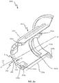
FIG. 2a illustrates a perspective cut-away view of a torque tube assembly in accordance with various embodiments; -
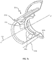
FIG. 2b illustrates a perspective cut-away view of a torque tube assembly in accordance with various embodiments; -
FIG. 2c illustrates a perspective cut-away view of a torque tube assembly in accordance with various embodiments; and -
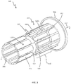
FIG. 3 illustrates an exploded perspective view of a torque tube assembly in accordance with various embodiments. - The detailed description of various embodiments herein makes reference to the accompanying drawings, which show various embodiments by way of illustration. While these various embodiments are described in sufficient detail to enable those skilled in the art to practice the disclosure, it should be understood that other embodiments may be realized and that logical, chemical, and mechanical changes may be made without departing from the spirit and scope of the disclosure. Thus, the detailed description herein is presented for purposes of illustration only and not of limitation.
- For example, the steps recited in any of the method or process descriptions may be executed in any order and are not necessarily limited to the order presented. Furthermore, any reference to singular includes plural embodiments, and any reference to more than one component or step may include a singular embodiment or step. Also, any reference to attached, fixed, connected, or the like may include permanent, removable, temporary, partial, full, and/or any other possible attachment option. Additionally, any reference to without contact (or similar phrases) may also include reduced contact or minimal contact.
- For example, in the context of the present disclosure, systems and methods may find particular use in connection with aircraft brake torque tubes. However, various aspects of the disclosed embodiments may be adapted for optimized performance with a variety of torque tubes and/or torque tube assemblies. As such, numerous applications of the present disclosure may be realized.
- In accordance with various embodiments and with reference to
FIG. 1 , a wheel andbrake assembly 100 may comprise awheel 102 at least partially surrounding a brake assembly. In various embodiments, the brake assembly comprises abrake stack 120 oriented about axis ofrotation 112.Brake stack 120 may comprise a plurality ofalternating stators 126 androtors 122. In various embodiments, the brake assembly may further comprise one ormore torque bars 108 configured to engage withrotors 122 aswheel 102,torque bars 108, androtors 122 rotate about axis ofrotation 112. - In various embodiments,
stators 126 may be stationary and may be coupled totorque tube 128. In various embodiments,torque tube 128 may be coupled to an axle sleeve and/oraxle 104 via a bushing. In various embodiments,torque tube 128 may comprise at least onespline 130 on its outer diameter. In various embodiments, the at least onespline 130 may be configured tocouple stators 126 totorque tube 128, thereby preventing rotation ofstators 126. In various embodiments, compression of rotatingrotors 122 againststationary stators 126 may cause torque to react through stators and intotorque tube 128.FIG. 1 provides a general understanding of portions of a wheel and brake assembly, and is not intended to limit the disclosure. - In various embodiments, and with reference to
FIG. 2a , atorque tube assembly 200a may comprise atorque tube 201a and asacrificial member 250a. In various embodiments,torque tube 201a may be oriented about an axis ofrotation 112. In various embodiments, thetorque tube 201 a may comprise abarrel portion 210a disposed between aflange 202a and aback leg 204a. In various embodiments,flange 202a may be disposed on a first axial end oftorque tube 201 a and may extend radially inward frombarrel portion 210a towards axis ofrotation 112. In various embodiments,back leg 204a may be disposed on a second axial end oftorque tube 201 a and extend radially outward frombarrel portion 210a. - In various embodiments,
torque tube 201a may further comprise at least onespline 230 disposed on an outer diameter ofbarrel portion 210a. In various embodiments,spline 230 may extend axially along the outer diameter ofbarrel portion 210a at least partially betweenflange 202a andback leg 204a. In various embodiments,torque tube 201 a may comprise a plurality of splines disposed radially about the outer diameter ofbarrel portion 210a. In various embodiments, eachspline 230 of the plurality of splines may be disposed substantially parallel to the others. - In various embodiments,
torque tube 201a may comprise atorque tube foot 260a configured to coupletorque tube 201 a to wheel axle 104 (with momentary reference toFIG. 1 ). In various embodiments,torque tube foot 260a may be disposed on, and extending circumferentially about, an inner diameter ofbarrel portion 210a. In various embodiments,torque tube foot 260a may be disposed axially betweenflange 202a andback leg 204a. In various embodiments,torque tube foot 260a may extend radially inward frombarrel portion 210a. In various embodiments,torque tube foot 260a andbarrel portion 210a may be disposed relative to one another so as to define acircumferential groove 262a therebetween. In various embodiments,circumferential groove 262a may be configured to receive asacrificial member 250a. In various embodiments,torque tube foot 260a may comprise at least oneaperture 264a extending axially from a first axial end oftorque tube foot 260a to a second axial end oftorque tube foot 260a. In various embodiments,aperture 264a may be configured to receive asacrificial member 250a. - In various embodiments,
torque tube 201 a may further comprise achannel 240. In various embodiments,channel 240 may comprise a slot, channel, depression, or the like and may be configured to receive asacrificial member 250a (described below). In various embodiments,channel 240 may be disposed inflange 202a. In various embodiments,channel 240 may be disposed in an inner diameter ofbarrel portion 210a. - In various embodiments,
channel 240 may be defined bychannel wall 242 and/or achannel base 244. In various embodiments,channel wall 242 may define a depth ofchannel 240 extending radially outward into a surface offlange 202a and/or the inner diameter ofbarrel portion 210a. In various embodiments,channel wall 242 may define a profile or shape ofchannel 240. In various embodiments,channel wall 242 andchannel base 244 may define a profile or shape ofchannel 240. In various embodiments,channel 240 may comprise a rectangular, prismatic, cylindrical, elliptical, or pyramidal shape. However, in various embodiments,channel 240 may comprise any shape suitable for use intorque tube 201 a. - In various embodiments,
channel wall 242 andchannel base 244 may be disposed perpendicular to one another. In various embodiments,channel wall 242 andchannel base 244 may be disposed relative to one another such that an obtuse angle theta (θ) is disposed therebetween. Stated differently, in various embodiments,channel 240 may comprise at least one obtuse-angled edge. In various embodiments,channel 240 may be configured such that asacrificial member 250a is not restricted from inward radial movement by any portion oftorque tube 201 a. - In various embodiments,
channel wall 242 andchannel base 244 may be disposed relative to one another such that an acute angle alpha (α) is disposed therebetween. Stated differently, in various embodiments,channel 240 may comprise at least one acute-angled edge. In various embodiments,channel 240 may be dove-tailed such that the acute-angled edge limits or restricts inward radial movement ofsacrificial member 250a. - In various embodiments,
channel 240 may be configured to receivesacrificial member 250a. In various embodiments,sacrificial member 250a may be configured to be in frictional contact with portions oftorque tube 201a so as to damp vibration oftorque tube 201a. In various embodiments, the vibration may comprise squeal vibration, or torsional motion of the non-rotating brake parts about the axle. In various embodiments, the vibration may comprise whirl mode vibration, or a wobble outside the rotational plane betweentorque tube 201 a andback leg 204a. In various embodiments, relative motion oftorque tube 201a andsacrificial member 250a dissipates, and thereby damps, the vibration. In various embodiments, relative motion oftorque tube 201a andsacrificial member 250a causes wear and/or degradation ofsacrificial member 250a but does not cause wear, degradation, and/or damage totorque tube 201a. - In various embodiments,
sacrificial member 250a may comprise a carbon composite material. In various embodiments,sacrificial member 250a may comprise carbon fiber-reinforced carbon, a composite material consisting of carbon fiber reinforced by a matrix of graphite. However, in various embodiments,sacrificial member 250a may comprise any material suitable for damping vibration oftorque tube 201 a. - In various embodiments,
sacrificial member 250a may be disposed inchannel 240. In various embodiments,sacrificial member 250a may comprise a shape complimentary tochannel 240. In various embodiments,sacrificial member 250a may be disposed and/or friction fit inchannel 240. In various embodiments,sacrificial member 250a may be coupled to at least one ofchannel 240 orflange 202a by at least one of arivet 270a, bolt, clamp, or other mechanical fastener. In various embodiments,sacrificial member 250a may extend fromflange 202a in an axial direction, partially towardstorque tube foot 260a. In various embodiments,sacrificial member 250a may extend between, and be disposed at least partially in bothchannel 240 andcircumferential groove 262a. - In various embodiments and with reference to
FIG. 2b ,sacrificial member 250b may be disposed incircumferential groove 262b. In various embodiments,sacrificial member 250b may comprise a shape complimentary tocircumferential groove 262b. In various embodiments,sacrificial member 250b may be disposed and/or friction fit incircumferential groove 262b. In various embodiments,sacrificial member 250b may be coupled to at least one ofcircumferential groove 262b ortorque tube foot 260b by at least one of arivet 270b, bolt, clamp, or other mechanical fastener. In various embodiments,sacrificial member 250b may extend fromtorque tube foot 260b in an axial direction at least partially towardsflange 202b. - In various embodiments,
sacrificial member 250b may be configured to be in frictional contact with portions oftorque tube 201b so as to damp vibration oftorque tube 201b. In various embodiments, the vibration may comprise squeal vibration, or torsional motion of the non-rotating brake parts about the axle. In various embodiments, the vibration may comprise whirl mode vibration, or a wobble outside the rotational plane betweentorque tube 201b andback leg 204b. In various embodiments, relative motion oftorque tube 201b andsacrificial member 250b dissipates, and thereby damps, the vibration. In various embodiments, relative motion oftorque tube 201b andsacrificial member 250b causes wear and/or degradation ofsacrificial member 250b but does not cause wear, degradation, and/or damage totorque tube 201b. - In various embodiments,
sacrificial member 250b may comprise a carbon composite material. In various embodiments,sacrificial member 250b may comprise carbon fiber-reinforced carbon, a composite material consisting of carbon fiber reinforced by a matrix of graphite. However, in various embodiments,sacrificial member 250b may comprise any material suitable for damping vibration oftorque tube 201b. - In various embodiments and with reference to
FIGs. 2a and2c ,sacrificial member 250a, 250c may be disposed at least partially in aperture 264. In various embodiments,sacrificial member 250a, 250c may comprise a shape complimentary toaperture sacrificial member 250a, 250c may be floated and/or friction fit inaperture sacrificial member 250a, 250c may extend throughaperture 264a, 164c in an axial direction at least partially towardsback leg - In various embodiments,
sacrificial member 250a, 250c may comprise afriction face sacrificial member 250a, 250c in frictional contact with the inner diameter ofbarrel portion friction face torque tube friction face barrel portion friction face barrel portion friction face - In various embodiments, sacrificial member 250c may be configured to be in frictional contact with portions of
torque tube 201c so as to damp vibration oftorque tube 201 c. In various embodiments, the vibration may comprise squeal vibration, or torsional motion of the non-rotating brake parts about the axle. In various embodiments, the vibration may comprise whirl mode vibration, or a wobble outside the rotational plane betweentorque tube 201c andback leg 204c. In various embodiments, relative motion oftorque tube 201c and sacrificial member 250c dissipates, and thereby damps, the vibration. In various embodiments, relative motion oftorque tube 201c and sacrificial member 250c causes wear and/or degradation of sacrificial member 250c but does not cause wear, degradation, and/or damage totorque tube 201c. - In various embodiments, sacrificial member 250c may comprise a carbon composite material. In various embodiments, sacrificial member 250c may comprise carbon fiber-reinforced carbon, a composite material consisting of carbon fiber reinforced by a matrix of graphite. However, in various embodiments, sacrificial member 250c may comprise any material suitable for damping vibration of
torque tube 201 c. - In various embodiments and with reference to
FIG. 3 , atorque tube assembly 300 may comprise atorque tube 301 and asacrificial member 350. In various embodiments,torque tube 301 may be oriented about an axis ofrotation 112. In various embodiments, thetorque tube 301 may comprise abarrel portion 310 disposed between aflange 302 and aback leg 304. In various embodiments,flange 302 may be disposed on a first axial end oftorque tube 301 and may extend radially inward frombarrel portion 310 towards axis ofrotation 112. In various embodiments,back leg 304 may be disposed on a second axial end oftorque tube 301 and extend radially outward frombarrel portion 310. - In various embodiments,
torque tube 301 may further comprise at least onespline barrel portion 310. In various embodiments,spline barrel portion 310 at least partially betweenflange 302 andback leg 304. In various embodiments,torque tube 301 may comprise a plurality of splines disposed radially about the outer diameter ofbarrel portion 310. In various embodiments, eachspline - In various embodiments,
torque tube 301 may further comprise achannel 340. In various embodiments,channel 340 may comprise a slot, channel, depression, or the like and may be configured to receive asacrificial member 350. In various embodiments,channel 340 may be disposed in an outer diameter ofbarrel portion 310. - In various embodiments,
channel 340 may be defined bychannel wall 342 and/or achannel base 344. In various embodiments,channel wall 342 may define a depth ofchannel 340 extending radially inward from the outer diameter ofbarrel portion 310. In various embodiments,channel wall 342 may define a profile or shape ofchannel 340. In various embodiments,channel wall 342 andchannel base 344 may define a profile or shape ofchannel 340. In various embodiments,channel 340 may comprise a rectangular, prismatic, cylindrical, elliptical, or pyramidal shape. However, in various embodiments,channel 340 may comprise any shape suitable for use intorque tube 301. - In various embodiments,
channel wall 342 andchannel base 344 may be disposed perpendicular to one another. In various embodiments,channel wall 342 andchannel base 344 may be disposed relative to one another such that an obtuse angle theta (O) is disposed therebetween. Stated differently, in various embodiments,channel 340 may comprise at least one obtuse-angled edge. In various embodiments,channel 340 may be configured such that asacrificial member 350 is not restricted from outward radial movement by any portion oftorque tube 301. - In various embodiments,
channel wall 342 andchannel base 344 may be disposed relative to one another such that an acute angle alpha (α) is disposed therebetween. Stated differently, in various embodiments,channel 340 may comprise at least one acute-angled edge. In various embodiments,channel 340 may be dove-tailed such that the acute-angled edge limits or restricts outward radial movement ofsacrificial member 350. - In various embodiments,
channel 340 may extend fromflange 302 in an axial direction partially towards torque tube foot backleg 304. In various embodiments,channel 340 may extend in an axial direction from the first axial end oftorque tube 301 to the second axial end oftorque tube 301. In various embodiments,channel 340 may extend in a radial direction from afirst spline 330a partially towards asecond spline 330b. In various embodiments,channel 340 may extend in a radial direction from thefirst spline 330a to thesecond spline 330b. - In various embodiments,
channel 340 may be configured to receivesacrificial member 350. In various embodiments,sacrificial member 350 may be configured to be in frictional contact with portions oftorque tube 301 so as to damp vibration oftorque tube 301. In various embodiments, the vibration may comprise squeal vibration, or torsional motion of the non-rotating brake parts about the axle. In various embodiments, the vibration may comprise whirl mode vibration, or a wobble outside the rotational plane betweentorque tube 301 andback leg 304. In various embodiments, relative motion oftorque tube 301 andsacrificial member 350 dissipates, and thereby damps, the vibration. In various embodiments, relative motion oftorque tube 301 andsacrificial member 350 causes wear and/or degradation ofsacrificial member 350 but does not cause wear, degradation, and/or damage totorque tube 301. - In various embodiments,
sacrificial member 350 may comprise a carbon composite material. In various embodiments,sacrificial member 350 may comprise carbon fiber-reinforced carbon, a composite material consisting of carbon fiber reinforced by a matrix of graphite. However, in various embodiments,sacrificial member 350 may comprise any material suitable for damping vibration oftorque tube 301. - In various embodiments,
sacrificial member 350 may be disposed inchannel 340. In various embodiments,sacrificial member 350 may comprise a shape complimentary tochannel 340. In various embodiments,sacrificial member 350 may be floated and/or friction fit inchannel 340. In various embodiments,sacrificial member 350 may be coupled totorque tube 301 by at least one of arivet 370, bolt, clamp, or other mechanical fastener. - In various embodiments,
sacrificial member 350 may comprise afriction face 380 disposed on a portion ofsacrificial member 350 in frictional contact withchannel 340. In various embodiments,friction face 380 may be configured to damp vibration oftorque tube 301 through interfacial friction betweenfriction face 380 andchannel 340. In various embodiments,friction face 380 may comprise a shape complimentary tochannel 340. - Benefits, other advantages, and solutions to problems have been described herein with regard to specific embodiments. Furthermore, the connecting lines shown in the various figures contained herein are intended to represent exemplary functional relationships and/or physical couplings between the various elements. It should be noted that many alternative or additional functional relationships or physical connections may be present in a practical system. However, the benefits, advantages, solutions to problems, and any elements that may cause any benefit, advantage, or solution to occur or become more pronounced are not to be construed as critical, required, or essential features or elements of the disclosure. The scope of the disclosure is accordingly to be limited by nothing other than the appended claims, in which reference to an element in the singular is not intended to mean "one and only one" unless explicitly so stated, but rather "one or more." Moreover, where a phrase similar to "at least one of A, B, or C" is used in the claims, it is intended that the phrase be interpreted to mean that A alone may be present in an embodiment, B alone may be present in an embodiment, C alone may be present in an embodiment, or that any combination of the elements A, B and C may be present in a single embodiment; for example, A and B, A and C, B and C, or A and B and C. Different cross-hatching is used throughout the figures to denote different parts but not necessarily to denote the same or different materials.
- Devices and methods are provided herein. In the detailed description herein, references to "one embodiment", "an embodiment", "various embodiments", etc., indicate that the embodiment described may include a particular feature, structure, or characteristic, but every embodiment may not necessarily include the particular feature, structure, or characteristic. Moreover, such phrases are not necessarily referring to the same embodiment. Further, when a particular feature, structure, or characteristic is described in connection with an embodiment, it is submitted that it is within the knowledge of one skilled in the art to affect such feature, structure, or characteristic in connection with other embodiments whether or not explicitly described. After reading the description, it will be apparent to one skilled in the relevant art(s) how to implement the disclosure in alternative embodiments.
- Furthermore, no element, component, or method step in the present disclosure is intended to be dedicated to the public regardless of whether the element, component, or method step is explicitly recited in the claims. As used herein, the terms "comprises", "comprising", or any other variation thereof, are intended to cover a non-exclusive inclusion, such that a process, method, article, or apparatus that comprises a list of elements does not include only those elements but may include other elements not expressly listed or inherent to such process, method, article, or apparatus.
Claims (15)
- A torque tube (201 a) comprising:a barrel portion (210a) disposed between a flange (202a) and a back leg (204a), the flange (202a) extending radially inward towards an axis of rotation and the back leg (204a) extending radially outward from the barrel portion (210a); anda channel (240) defined by a channel wall (242) and disposed in at least one of the barrel portion (210a) and the flange (202a), the channel (240) being configured to receive a sacrificial member (250a).
- The torque tube (201 a) of claim 1, further comprising a torque tube foot (260a) disposed on an inner diameter of the barrel portion (210a), the torque tube foot (260a) comprising at least one of a groove (262b) or an aperture (264a) configured to receive the sacrificial member (250a).
- The torque tube of claims 1 or 2, wherein the channel wall (242) comprises an obtuse-angled edge.
- The torque tube of any of claims 1 or 2, wherein the channel wall (242) comprises an acute-angled edge.
- The torque tube of any preceding claim, wherein the channel (240) is disposed in an outer diameter of the barrel portion;
wherein the channel (240) extends in an axial direction at least partially between the flange and the back leg; and
a first spline (230) disposed on the outer diameter of the barrel portion (210a); and
a second spline (230) disposed on the outer diameter of the barrel portion and substantially parallel to the first spline, wherein the channel (240) extends in a radial direction at least partially between the first spline and the second spline. - A torque tube assembly (200a) comprising:a torque tube (201a) having a barrel portion (210a) disposed between a flange (202a) and a back leg (204a), the flange (202a) extending radially inward towards an axis of rotation and the back leg (204a) extending radially outward from the barrel portion; anda sacrificial member (250a) disposed on at least one of the flange (202a) and a torque tube foot (260a), the torque tube foot(260a) being disposed on an inner diameter of the barrel portion (210a), wherein a friction face of the sacrificial member (250a) is in frictional contact with the inner diameter of the barrel portion (210a).
- The torque tube assembly of claim 6, wherein the sacrificial member (250a) comprises a carbon composite material; and/or further comprising a rivet (270a) configured to couple the sacrificial member to at least one of the flange and the torque tube foot.
- The torque tube assembly of claims 6 or 7, wherein the sacrificial member (250a) is disposed on the flange and extends in an axial direction at least partially between the flange and the torque tube foot; and further comprising:a channel (240) defined by a channel wall (242) and disposed in the flange (202a), wherein the sacrificial member (250a) is at least partially disposed in the channel.
- The torque tube assembly of claim 8, wherein the channel wall (242) comprises an obtuse-angled edge.
- The torque tube assembly of claim 8, wherein the channel wall (242) comprises an acute-angled edge.
- The torque tube assembly of any of claims 6-10, wherein the sacrificial member (250a) is disposed on the torque tube foot and extends in an axial direction at least partially between the torque tube foot and the flange.
- A torque tube assembly comprising:a torque tube (201 a) comprising a barrel portion (210a) disposed between a flange (202a) and a back leg (204a), the back leg (204a) extending radially outward from the barrel portion, and a channel (240) defined by a channel wall (242) and disposed in an outer diameter of the barrel portion (210a); anda sacrificial member (250a) disposed in the channel (240), wherein a friction face of the sacrificial member (250a) is in frictional contact with the channel (240).
- The torque tube assembly of claim 12, wherein the channel wall (242) comprises an obtuse-angled edge.
- The torque tube assembly of claim 12, wherein the channel wall (242) comprises an acute-angled edge.
- The torque tube assembly of any of claims 12-14, wherein the channel (240) extends in an axial direction at least partially between the flange (202a) and the back leg (204a); and/or further comprising:a first spline (230) disposed on an outer diameter of the barrel portion; anda second spline (230) disposed on the outer diameter of the barrel portion and substantially parallel to the first spline, wherein the channel extends in a radial direction at least partially between the first spline and the second spline.
Applications Claiming Priority (1)
| Application Number | Priority Date | Filing Date | Title |
|---|---|---|---|
| US14/976,744 US9670975B1 (en) | 2015-12-21 | 2015-12-21 | Torque tube damping devices and assemblies |
Publications (2)
| Publication Number | Publication Date |
|---|---|
| EP3196499A1 true EP3196499A1 (en) | 2017-07-26 |
| EP3196499B1 EP3196499B1 (en) | 2021-03-03 |
Family
ID=57681283
Family Applications (1)
| Application Number | Title | Priority Date | Filing Date |
|---|---|---|---|
| EP16204302.0A Active EP3196499B1 (en) | 2015-12-21 | 2016-12-15 | Torque tube assembly |
Country Status (2)
| Country | Link |
|---|---|
| US (1) | US9670975B1 (en) |
| EP (1) | EP3196499B1 (en) |
Families Citing this family (7)
| Publication number | Priority date | Publication date | Assignee | Title |
|---|---|---|---|---|
| FR3026717B1 (en) * | 2014-10-03 | 2016-11-25 | Messier Bugatti Dowty | AIRCRAFT ENGINEER |
| US10598209B2 (en) * | 2017-09-08 | 2020-03-24 | Goodrich Corporation | Aircraft brake torque load reaction through landing gear bogie structure |
| US10677300B2 (en) * | 2018-02-02 | 2020-06-09 | Goodrich Corporation | Hybrid torque tube |
| US20220356915A1 (en) * | 2021-05-04 | 2022-11-10 | Meggitt Aircraft Braking Systems Corporation | Reinforced torque tubes |
| US20230024676A1 (en) | 2021-07-22 | 2023-01-26 | Gonzalo Fuentes Iriarte | Systems and methods for electric vehicle energy recovery |
| US11834159B2 (en) | 2021-10-18 | 2023-12-05 | Goodrich Corporation | Torque button bushing |
| US12454350B2 (en) * | 2022-08-10 | 2025-10-28 | Goodrich Corporation | Tapered torque plate barrel for improving dynamic stability |
Citations (4)
| Publication number | Priority date | Publication date | Assignee | Title |
|---|---|---|---|---|
| US4576255A (en) * | 1983-06-30 | 1986-03-18 | Societe Anonyme D.B.A. | Multi-disc brakes |
| WO1994002753A1 (en) * | 1992-07-23 | 1994-02-03 | Allied-Signal Inc. | Aircraft brake vibration damper |
| US5323881A (en) * | 1992-04-17 | 1994-06-28 | Aircraft Braking Systems Corporation | Configuration for a disk brake torque tube |
| US6003641A (en) * | 1996-01-16 | 1999-12-21 | Mcdonnell Douglas Corporation | Wheel and brake assembly |
Family Cites Families (7)
| Publication number | Priority date | Publication date | Assignee | Title |
|---|---|---|---|---|
| US3357519A (en) * | 1966-03-21 | 1967-12-12 | Bendix Corp | Aircraft brake damper mechanism |
| US3368653A (en) * | 1966-05-26 | 1968-02-13 | Bendix Corp | Aircraft brake damper mechanism |
| EP0774595B1 (en) * | 1995-11-16 | 2002-05-08 | The B.F. Goodrich Company | Nested damping device with relative motion |
| US5915503A (en) * | 1995-11-16 | 1999-06-29 | The B.F. Goodrich Company | Brake rod having a bending mode coulomb damper |
| US6631793B2 (en) * | 2001-12-13 | 2003-10-14 | Aircraft Braking Systems Corporation | Torque tube and conical back plate for aircraft brake systems |
| GB2438633B (en) | 2006-05-31 | 2010-12-01 | Tisics Ltd | Reinforced splines and their manufacture |
| US9518601B2 (en) | 2013-02-05 | 2016-12-13 | Ccdi Composites Inc. | Composite tube for torque and/or load transmissions and related methods |
-
2015
- 2015-12-21 US US14/976,744 patent/US9670975B1/en active Active
-
2016
- 2016-12-15 EP EP16204302.0A patent/EP3196499B1/en active Active
Patent Citations (4)
| Publication number | Priority date | Publication date | Assignee | Title |
|---|---|---|---|---|
| US4576255A (en) * | 1983-06-30 | 1986-03-18 | Societe Anonyme D.B.A. | Multi-disc brakes |
| US5323881A (en) * | 1992-04-17 | 1994-06-28 | Aircraft Braking Systems Corporation | Configuration for a disk brake torque tube |
| WO1994002753A1 (en) * | 1992-07-23 | 1994-02-03 | Allied-Signal Inc. | Aircraft brake vibration damper |
| US6003641A (en) * | 1996-01-16 | 1999-12-21 | Mcdonnell Douglas Corporation | Wheel and brake assembly |
Also Published As
| Publication number | Publication date |
|---|---|
| US9670975B1 (en) | 2017-06-06 |
| US20170175830A1 (en) | 2017-06-22 |
| EP3196499B1 (en) | 2021-03-03 |
Similar Documents
| Publication | Publication Date | Title |
|---|---|---|
| EP3196499B1 (en) | Torque tube assembly | |
| CN104104166B (en) | Rotor member, rotor including rotor member, manufacturing method thereof, and rotating electric machine | |
| JP6140106B2 (en) | Rotor member fixed to rotating shaft portion of rotating electrical machine, rotor, rotating electrical machine, and method for disassembling rotor | |
| JP6159572B2 (en) | Torque transmission device | |
| EP3168491B1 (en) | Single fastener brake disk insert retainer | |
| RS57722B1 (en) | Improved elastic bushing | |
| CN104279237B (en) | Casing with internal spline broaching system | |
| JP6427602B2 (en) | Torque transmission device | |
| US20150037158A1 (en) | Torque converter with stamped stator | |
| EP2938897B1 (en) | Torque limiting assembly | |
| EP3115636B1 (en) | Multi-leaved core brake disks and assemblies | |
| EP3228896A1 (en) | Multi-piece torque tube assembly to mitigate vibration | |
| EP3187746A1 (en) | Plate assemblies including floating wear linings for multi-disk brake system and methods for reducing vibration in a multi-disk brake system | |
| WO2015148647A1 (en) | Methods and systems to mount a rotor to a shaft | |
| EP3540259B1 (en) | Torque button lock clip | |
| US10495162B2 (en) | Disc brake rotor assembly | |
| CN204985426U (en) | Fan, motor element and centrifugation friction clutch thereof | |
| NZ211758A (en) | Shaft flexible coupling: elastomeric shear sleeve with hard beads at ends | |
| KR101551069B1 (en) | Apparatus for transferring driving force at wheel for vehicle | |
| WO2017184900A1 (en) | Centrifugal pendulum absorber including springs fixed to circumferential edges of masses | |
| US20200040952A1 (en) | Extended torque tube | |
| JP2021028524A (en) | Fixture | |
| US20110028225A1 (en) | Slip clutch | |
| US8083473B2 (en) | Interface for a stamped stator and a one-way clutch | |
| US20190120302A1 (en) | Torque plate barrel having blended barrel support pedestal |
Legal Events
| Date | Code | Title | Description |
|---|---|---|---|
| PUAI | Public reference made under article 153(3) epc to a published international application that has entered the european phase |
Free format text: ORIGINAL CODE: 0009012 |
|
| STAA | Information on the status of an ep patent application or granted ep patent |
Free format text: STATUS: THE APPLICATION HAS BEEN PUBLISHED |
|
| AK | Designated contracting states |
Kind code of ref document: A1 Designated state(s): AL AT BE BG CH CY CZ DE DK EE ES FI FR GB GR HR HU IE IS IT LI LT LU LV MC MK MT NL NO PL PT RO RS SE SI SK SM TR |
|
| AX | Request for extension of the european patent |
Extension state: BA ME |
|
| STAA | Information on the status of an ep patent application or granted ep patent |
Free format text: STATUS: REQUEST FOR EXAMINATION WAS MADE |
|
| 17P | Request for examination filed |
Effective date: 20180125 |
|
| RBV | Designated contracting states (corrected) |
Designated state(s): AL AT BE BG CH CY CZ DE DK EE ES FI FR GB GR HR HU IE IS IT LI LT LU LV MC MK MT NL NO PL PT RO RS SE SI SK SM TR |
|
| GRAP | Despatch of communication of intention to grant a patent |
Free format text: ORIGINAL CODE: EPIDOSNIGR1 |
|
| STAA | Information on the status of an ep patent application or granted ep patent |
Free format text: STATUS: GRANT OF PATENT IS INTENDED |
|
| INTG | Intention to grant announced |
Effective date: 20200930 |
|
| GRAS | Grant fee paid |
Free format text: ORIGINAL CODE: EPIDOSNIGR3 |
|
| GRAA | (expected) grant |
Free format text: ORIGINAL CODE: 0009210 |
|
| STAA | Information on the status of an ep patent application or granted ep patent |
Free format text: STATUS: THE PATENT HAS BEEN GRANTED |
|
| AK | Designated contracting states |
Kind code of ref document: B1 Designated state(s): AL AT BE BG CH CY CZ DE DK EE ES FI FR GB GR HR HU IE IS IT LI LT LU LV MC MK MT NL NO PL PT RO RS SE SI SK SM TR |
|
| REG | Reference to a national code |
Ref country code: GB Ref legal event code: FG4D |
|
| REG | Reference to a national code |
Ref country code: AT Ref legal event code: REF Ref document number: 1367540 Country of ref document: AT Kind code of ref document: T Effective date: 20210315 Ref country code: CH Ref legal event code: EP |
|
| REG | Reference to a national code |
Ref country code: DE Ref legal event code: R096 Ref document number: 602016053497 Country of ref document: DE |
|
| REG | Reference to a national code |
Ref country code: IE Ref legal event code: FG4D |
|
| REG | Reference to a national code |
Ref country code: LT Ref legal event code: MG9D |
|
| PG25 | Lapsed in a contracting state [announced via postgrant information from national office to epo] |
Ref country code: NO Free format text: LAPSE BECAUSE OF FAILURE TO SUBMIT A TRANSLATION OF THE DESCRIPTION OR TO PAY THE FEE WITHIN THE PRESCRIBED TIME-LIMIT Effective date: 20210603 Ref country code: GR Free format text: LAPSE BECAUSE OF FAILURE TO SUBMIT A TRANSLATION OF THE DESCRIPTION OR TO PAY THE FEE WITHIN THE PRESCRIBED TIME-LIMIT Effective date: 20210604 Ref country code: HR Free format text: LAPSE BECAUSE OF FAILURE TO SUBMIT A TRANSLATION OF THE DESCRIPTION OR TO PAY THE FEE WITHIN THE PRESCRIBED TIME-LIMIT Effective date: 20210303 Ref country code: FI Free format text: LAPSE BECAUSE OF FAILURE TO SUBMIT A TRANSLATION OF THE DESCRIPTION OR TO PAY THE FEE WITHIN THE PRESCRIBED TIME-LIMIT Effective date: 20210303 Ref country code: LT Free format text: LAPSE BECAUSE OF FAILURE TO SUBMIT A TRANSLATION OF THE DESCRIPTION OR TO PAY THE FEE WITHIN THE PRESCRIBED TIME-LIMIT Effective date: 20210303 Ref country code: BG Free format text: LAPSE BECAUSE OF FAILURE TO SUBMIT A TRANSLATION OF THE DESCRIPTION OR TO PAY THE FEE WITHIN THE PRESCRIBED TIME-LIMIT Effective date: 20210603 |
|
| REG | Reference to a national code |
Ref country code: NL Ref legal event code: MP Effective date: 20210303 |
|
| REG | Reference to a national code |
Ref country code: AT Ref legal event code: MK05 Ref document number: 1367540 Country of ref document: AT Kind code of ref document: T Effective date: 20210303 |
|
| PG25 | Lapsed in a contracting state [announced via postgrant information from national office to epo] |
Ref country code: PL Free format text: LAPSE BECAUSE OF FAILURE TO SUBMIT A TRANSLATION OF THE DESCRIPTION OR TO PAY THE FEE WITHIN THE PRESCRIBED TIME-LIMIT Effective date: 20210303 Ref country code: RS Free format text: LAPSE BECAUSE OF FAILURE TO SUBMIT A TRANSLATION OF THE DESCRIPTION OR TO PAY THE FEE WITHIN THE PRESCRIBED TIME-LIMIT Effective date: 20210303 Ref country code: LV Free format text: LAPSE BECAUSE OF FAILURE TO SUBMIT A TRANSLATION OF THE DESCRIPTION OR TO PAY THE FEE WITHIN THE PRESCRIBED TIME-LIMIT Effective date: 20210303 Ref country code: SE Free format text: LAPSE BECAUSE OF FAILURE TO SUBMIT A TRANSLATION OF THE DESCRIPTION OR TO PAY THE FEE WITHIN THE PRESCRIBED TIME-LIMIT Effective date: 20210303 |
|
| PG25 | Lapsed in a contracting state [announced via postgrant information from national office to epo] |
Ref country code: NL Free format text: LAPSE BECAUSE OF FAILURE TO SUBMIT A TRANSLATION OF THE DESCRIPTION OR TO PAY THE FEE WITHIN THE PRESCRIBED TIME-LIMIT Effective date: 20210303 |
|
| PG25 | Lapsed in a contracting state [announced via postgrant information from national office to epo] |
Ref country code: AT Free format text: LAPSE BECAUSE OF FAILURE TO SUBMIT A TRANSLATION OF THE DESCRIPTION OR TO PAY THE FEE WITHIN THE PRESCRIBED TIME-LIMIT Effective date: 20210303 Ref country code: SM Free format text: LAPSE BECAUSE OF FAILURE TO SUBMIT A TRANSLATION OF THE DESCRIPTION OR TO PAY THE FEE WITHIN THE PRESCRIBED TIME-LIMIT Effective date: 20210303 Ref country code: CZ Free format text: LAPSE BECAUSE OF FAILURE TO SUBMIT A TRANSLATION OF THE DESCRIPTION OR TO PAY THE FEE WITHIN THE PRESCRIBED TIME-LIMIT Effective date: 20210303 Ref country code: EE Free format text: LAPSE BECAUSE OF FAILURE TO SUBMIT A TRANSLATION OF THE DESCRIPTION OR TO PAY THE FEE WITHIN THE PRESCRIBED TIME-LIMIT Effective date: 20210303 |
|
| PG25 | Lapsed in a contracting state [announced via postgrant information from national office to epo] |
Ref country code: PT Free format text: LAPSE BECAUSE OF FAILURE TO SUBMIT A TRANSLATION OF THE DESCRIPTION OR TO PAY THE FEE WITHIN THE PRESCRIBED TIME-LIMIT Effective date: 20210705 Ref country code: RO Free format text: LAPSE BECAUSE OF FAILURE TO SUBMIT A TRANSLATION OF THE DESCRIPTION OR TO PAY THE FEE WITHIN THE PRESCRIBED TIME-LIMIT Effective date: 20210303 Ref country code: SK Free format text: LAPSE BECAUSE OF FAILURE TO SUBMIT A TRANSLATION OF THE DESCRIPTION OR TO PAY THE FEE WITHIN THE PRESCRIBED TIME-LIMIT Effective date: 20210303 Ref country code: IS Free format text: LAPSE BECAUSE OF FAILURE TO SUBMIT A TRANSLATION OF THE DESCRIPTION OR TO PAY THE FEE WITHIN THE PRESCRIBED TIME-LIMIT Effective date: 20210703 |
|
| REG | Reference to a national code |
Ref country code: DE Ref legal event code: R097 Ref document number: 602016053497 Country of ref document: DE |
|
| PLBE | No opposition filed within time limit |
Free format text: ORIGINAL CODE: 0009261 |
|
| STAA | Information on the status of an ep patent application or granted ep patent |
Free format text: STATUS: NO OPPOSITION FILED WITHIN TIME LIMIT |
|
| PG25 | Lapsed in a contracting state [announced via postgrant information from national office to epo] |
Ref country code: DK Free format text: LAPSE BECAUSE OF FAILURE TO SUBMIT A TRANSLATION OF THE DESCRIPTION OR TO PAY THE FEE WITHIN THE PRESCRIBED TIME-LIMIT Effective date: 20210303 Ref country code: AL Free format text: LAPSE BECAUSE OF FAILURE TO SUBMIT A TRANSLATION OF THE DESCRIPTION OR TO PAY THE FEE WITHIN THE PRESCRIBED TIME-LIMIT Effective date: 20210303 Ref country code: ES Free format text: LAPSE BECAUSE OF FAILURE TO SUBMIT A TRANSLATION OF THE DESCRIPTION OR TO PAY THE FEE WITHIN THE PRESCRIBED TIME-LIMIT Effective date: 20210303 |
|
| 26N | No opposition filed |
Effective date: 20211206 |
|
| PG25 | Lapsed in a contracting state [announced via postgrant information from national office to epo] |
Ref country code: SI Free format text: LAPSE BECAUSE OF FAILURE TO SUBMIT A TRANSLATION OF THE DESCRIPTION OR TO PAY THE FEE WITHIN THE PRESCRIBED TIME-LIMIT Effective date: 20210303 |
|
| PG25 | Lapsed in a contracting state [announced via postgrant information from national office to epo] |
Ref country code: IT Free format text: LAPSE BECAUSE OF FAILURE TO SUBMIT A TRANSLATION OF THE DESCRIPTION OR TO PAY THE FEE WITHIN THE PRESCRIBED TIME-LIMIT Effective date: 20210303 |
|
| PG25 | Lapsed in a contracting state [announced via postgrant information from national office to epo] |
Ref country code: IS Free format text: LAPSE BECAUSE OF FAILURE TO SUBMIT A TRANSLATION OF THE DESCRIPTION OR TO PAY THE FEE WITHIN THE PRESCRIBED TIME-LIMIT Effective date: 20210703 |
|
| REG | Reference to a national code |
Ref country code: DE Ref legal event code: R119 Ref document number: 602016053497 Country of ref document: DE |
|
| PG25 | Lapsed in a contracting state [announced via postgrant information from national office to epo] |
Ref country code: MC Free format text: LAPSE BECAUSE OF FAILURE TO SUBMIT A TRANSLATION OF THE DESCRIPTION OR TO PAY THE FEE WITHIN THE PRESCRIBED TIME-LIMIT Effective date: 20210303 |
|
| REG | Reference to a national code |
Ref country code: CH Ref legal event code: PL |
|
| REG | Reference to a national code |
Ref country code: BE Ref legal event code: MM Effective date: 20211231 |
|
| PG25 | Lapsed in a contracting state [announced via postgrant information from national office to epo] |
Ref country code: LU Free format text: LAPSE BECAUSE OF NON-PAYMENT OF DUE FEES Effective date: 20211215 Ref country code: IE Free format text: LAPSE BECAUSE OF NON-PAYMENT OF DUE FEES Effective date: 20211215 Ref country code: DE Free format text: LAPSE BECAUSE OF NON-PAYMENT OF DUE FEES Effective date: 20220701 |
|
| PG25 | Lapsed in a contracting state [announced via postgrant information from national office to epo] |
Ref country code: BE Free format text: LAPSE BECAUSE OF NON-PAYMENT OF DUE FEES Effective date: 20211231 |
|
| PG25 | Lapsed in a contracting state [announced via postgrant information from national office to epo] |
Ref country code: LI Free format text: LAPSE BECAUSE OF NON-PAYMENT OF DUE FEES Effective date: 20211231 Ref country code: CH Free format text: LAPSE BECAUSE OF NON-PAYMENT OF DUE FEES Effective date: 20211231 |
|
| PG25 | Lapsed in a contracting state [announced via postgrant information from national office to epo] |
Ref country code: HU Free format text: LAPSE BECAUSE OF FAILURE TO SUBMIT A TRANSLATION OF THE DESCRIPTION OR TO PAY THE FEE WITHIN THE PRESCRIBED TIME-LIMIT; INVALID AB INITIO Effective date: 20161215 |
|
| P01 | Opt-out of the competence of the unified patent court (upc) registered |
Effective date: 20230522 |
|
| PG25 | Lapsed in a contracting state [announced via postgrant information from national office to epo] |
Ref country code: CY Free format text: LAPSE BECAUSE OF FAILURE TO SUBMIT A TRANSLATION OF THE DESCRIPTION OR TO PAY THE FEE WITHIN THE PRESCRIBED TIME-LIMIT Effective date: 20210303 |
|
| PG25 | Lapsed in a contracting state [announced via postgrant information from national office to epo] |
Ref country code: MK Free format text: LAPSE BECAUSE OF FAILURE TO SUBMIT A TRANSLATION OF THE DESCRIPTION OR TO PAY THE FEE WITHIN THE PRESCRIBED TIME-LIMIT Effective date: 20210303 |
|
| PG25 | Lapsed in a contracting state [announced via postgrant information from national office to epo] |
Ref country code: MT Free format text: LAPSE BECAUSE OF FAILURE TO SUBMIT A TRANSLATION OF THE DESCRIPTION OR TO PAY THE FEE WITHIN THE PRESCRIBED TIME-LIMIT Effective date: 20210303 |
|
| PG25 | Lapsed in a contracting state [announced via postgrant information from national office to epo] |
Ref country code: TR Free format text: LAPSE BECAUSE OF FAILURE TO SUBMIT A TRANSLATION OF THE DESCRIPTION OR TO PAY THE FEE WITHIN THE PRESCRIBED TIME-LIMIT Effective date: 20210303 |
|
| PGFP | Annual fee paid to national office [announced via postgrant information from national office to epo] |
Ref country code: GB Payment date: 20251119 Year of fee payment: 10 |
|
| PGFP | Annual fee paid to national office [announced via postgrant information from national office to epo] |
Ref country code: FR Payment date: 20251120 Year of fee payment: 10 |