EP3196464A1 - Compressor module - Google Patents
Compressor module Download PDFInfo
- Publication number
- EP3196464A1 EP3196464A1 EP14905733.3A EP14905733A EP3196464A1 EP 3196464 A1 EP3196464 A1 EP 3196464A1 EP 14905733 A EP14905733 A EP 14905733A EP 3196464 A1 EP3196464 A1 EP 3196464A1
- Authority
- EP
- European Patent Office
- Prior art keywords
- compressor
- floor member
- damping device
- gas cooler
- skid
- Prior art date
- Legal status (The legal status is an assumption and is not a legal conclusion. Google has not performed a legal analysis and makes no representation as to the accuracy of the status listed.)
- Granted
Links
Images


Classifications
-
- B—PERFORMING OPERATIONS; TRANSPORTING
- B63—SHIPS OR OTHER WATERBORNE VESSELS; RELATED EQUIPMENT
- B63H—MARINE PROPULSION OR STEERING
- B63H21/00—Use of propulsion power plant or units on vessels
- B63H21/30—Mounting of propulsion plant or unit, e.g. for anti-vibration purposes
-
- F—MECHANICAL ENGINEERING; LIGHTING; HEATING; WEAPONS; BLASTING
- F04—POSITIVE - DISPLACEMENT MACHINES FOR LIQUIDS; PUMPS FOR LIQUIDS OR ELASTIC FLUIDS
- F04B—POSITIVE-DISPLACEMENT MACHINES FOR LIQUIDS; PUMPS
- F04B41/00—Pumping installations or systems specially adapted for elastic fluids
-
- F—MECHANICAL ENGINEERING; LIGHTING; HEATING; WEAPONS; BLASTING
- F16—ENGINEERING ELEMENTS AND UNITS; GENERAL MEASURES FOR PRODUCING AND MAINTAINING EFFECTIVE FUNCTIONING OF MACHINES OR INSTALLATIONS; THERMAL INSULATION IN GENERAL
- F16M—FRAMES, CASINGS OR BEDS OF ENGINES, MACHINES OR APPARATUS, NOT SPECIFIC TO ENGINES, MACHINES OR APPARATUS PROVIDED FOR ELSEWHERE; STANDS; SUPPORTS
- F16M3/00—Portable or wheeled frames or beds, e.g. for emergency power-supply aggregates, compressor sets
-
- F—MECHANICAL ENGINEERING; LIGHTING; HEATING; WEAPONS; BLASTING
- F25—REFRIGERATION OR COOLING; COMBINED HEATING AND REFRIGERATION SYSTEMS; HEAT PUMP SYSTEMS; MANUFACTURE OR STORAGE OF ICE; LIQUEFACTION SOLIDIFICATION OF GASES
- F25B—REFRIGERATION MACHINES, PLANTS OR SYSTEMS; COMBINED HEATING AND REFRIGERATION SYSTEMS; HEAT PUMP SYSTEMS
- F25B31/00—Compressor arrangements
- F25B31/02—Compressor arrangements of motor-compressor units
-
- F—MECHANICAL ENGINEERING; LIGHTING; HEATING; WEAPONS; BLASTING
- F25—REFRIGERATION OR COOLING; COMBINED HEATING AND REFRIGERATION SYSTEMS; HEAT PUMP SYSTEMS; MANUFACTURE OR STORAGE OF ICE; LIQUEFACTION SOLIDIFICATION OF GASES
- F25B—REFRIGERATION MACHINES, PLANTS OR SYSTEMS; COMBINED HEATING AND REFRIGERATION SYSTEMS; HEAT PUMP SYSTEMS
- F25B2400/00—Component parts or details not otherwise provided for in this subclass
- F25B2400/07—Details of compressors or related parts
- F25B2400/071—Compressor mounted in a housing in which a condenser is integrated
-
- F—MECHANICAL ENGINEERING; LIGHTING; HEATING; WEAPONS; BLASTING
- F25—REFRIGERATION OR COOLING; COMBINED HEATING AND REFRIGERATION SYSTEMS; HEAT PUMP SYSTEMS; MANUFACTURE OR STORAGE OF ICE; LIQUEFACTION SOLIDIFICATION OF GASES
- F25B—REFRIGERATION MACHINES, PLANTS OR SYSTEMS; COMBINED HEATING AND REFRIGERATION SYSTEMS; HEAT PUMP SYSTEMS
- F25B2400/00—Component parts or details not otherwise provided for in this subclass
- F25B2400/23—Separators
-
- F—MECHANICAL ENGINEERING; LIGHTING; HEATING; WEAPONS; BLASTING
- F25—REFRIGERATION OR COOLING; COMBINED HEATING AND REFRIGERATION SYSTEMS; HEAT PUMP SYSTEMS; MANUFACTURE OR STORAGE OF ICE; LIQUEFACTION SOLIDIFICATION OF GASES
- F25B—REFRIGERATION MACHINES, PLANTS OR SYSTEMS; COMBINED HEATING AND REFRIGERATION SYSTEMS; HEAT PUMP SYSTEMS
- F25B2500/00—Problems to be solved
- F25B2500/01—Geometry problems, e.g. for reducing size
Definitions
- the present invention relates to a compressor module.
- Arrangements of a compressor and a drive unit therefor on a frame are known (for example, see Patent Document 1). Additionally, for large equipment that include a compressor and a drive unit therefor, a module structure in which a compressor and a drive unit therefor are assembled is employed as a floor member on which maintenance workers stand.
- Patent Document 1 US Application Publication No. 2013/0251555
- the present invention has an object of providing a compressor module that is low weight and has a low center of gravity.
- An aspect of the present invention is a compressor module, comprising: a floor member; a gas cooler mounted on the floor member; a compressor skid disposed on a side of the gas cooler opposite to where the floor member is located, the compressor skid being connected to the gas cooler; and a leg portion connected to the compressor skid and fixed to the floor member that supports the compressor skid, the leg portion providing a gap to dispose the gas cooler between the floor member and the compressor skid.
- the compressor skid preferably comprises a compressor that raises pressure of a gas and sends the gas to the gas cooler, a drive unit that drives the compressor, and a base plate on which the compressor and the drive unit are mounted.
- the leg portion preferably comprises a damping device fixed to the base plate, and a coupling member fixed to the damping device and fixed to the floor member.
- the damping device preferably comprises a first damping device, a second damping device disposed at a position spaced away from the first damping device, and a third damping device disposed at a position spaced away from the first damping device and the second damping device.
- the coupling member preferably comprises a first coupling member that couples to the first damping device and the floor member, a second coupling member that couples to the second damping device and the floor member, and a third coupling member that couples to the third damping device and the floor member; and at least a portion of the gas cooler is disposed within a space formed between the first coupling member, the second coupling member, and the third coupling member.
- the compressor module preferably further comprises: a second floor member disposed on a side of the compressor skid opposite to where the floor member is located; a first line mounted on the second floor member through which a gas supplied to the compressor skid flows; a second line mounted on the second floor member through which a gas supplied from the gas cooler flows; and a valve disposed on the second floor member for changing a flow rate of a gas in the first line and/or the second line.
- the compressor module according to any one of the aspects described above preferably further comprises a drain separator fixed to the floor member and connected to the gas cooler on a downstream side.
- the present invention can provide a compressor module that is low weight and has a low center of gravity.
- FIG. 1 is a perspective view of a compressor module 1 according to the present embodiment.
- FIG. 2 is a side view of the compressor module 1.
- FIG. 3 is a front view of the compressor module 1.
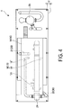
- FIG. 4 is a schematic plan view of a base plate 14 of the compressor module 1.
- the compressor module 1 of the present embodiment includes a frame 2, a compressor skid 10, a leg portion 15 that supports the compressor skid 10, a gas cooler 24, a drain separator 25, a line portion 30, and a valve.
- the frame 2 includes a first floor member 3 on which the compressor skid 10, the gas cooler 24, and the drain separator 25 are mounted and a second floor member 4 where a portion of the line portion 30 and the valve are disposed.
- the second floor member 4 is located above the first floor member 3.
- the frame 2 also includes a support 5 coupled to the first floor member 3 and the second floor member 4.
- the first floor member 3 is the floor member located at the bottom layer of the frame 2 of the compressor module 1.
- the second floor member 4 is disposed on the side of the compressor skid 10 opposite to where the first floor member 3 is located.
- Operation or maintenance workers for the compressor module 1 can stand on the first floor member 3 and the second floor member 4. Additionally, the first floor member 3 and the second floor member 4 are connected via an ascent/descent device 6 such as a ladder, stairs, or an elevator.
- an ascent/descent device 6 such as a ladder, stairs, or an elevator.
- the compressor skid 10 is disposed on the side of the gas cooler 24 opposite to where the first floor member 3 is located, and connected to the gas cooler 24 on the upstream side.
- the compressor skid 10 includes a compressor 11 that raises the pressure of the gas and sends it to the gas cooler 24, a drive unit 12 that drives the compressor 11, and the base plate 14 on which the compressor 11 and the drive unit 12 are mounted.
- the configuration of the compressor 11 and the drive unit 12 are not particularly limited.
- the drive unit 12 is a device that generates rotational driving force, and the compressor 11 and the drive unit 12 are connected via a speed increaser 13 that increases the speed of the drive unit 12.
- the base plate 14 is a rigid body on which the compressor 11 and the drive unit 12 are mounted. Note that the base plate 14 is not required to have a planar shape. A damping device 16 is fixed on the base plate 14 at three different positions spaced apart from one another. In the present embodiment, a tank (not illustrated) of lubricating oil for the compressor 11, drive unit 12, and the like may be mounted on the base plate 14.
- the leg portion 15 illustrated in FIGS. 3 and 4 is coupled to the compressor skid 10 and fixed to the first floor member 3.
- the leg portion 15 includes the damping device 16 fixed to the base plate 14 and a coupling member 20 fixed to the damping device 16 and fixed to the first floor member 3.
- the damping device 16 includes a first damping device 17 fixed to the base plate 14, a second damping device 18 fixed to the base plate 14 at a position spaced from the first damping device 17, and a third damping device 19 fixed to the base plate 14 at a position spaced from both the first damping device 17 and the second damping device 18.
- the damping devices 16 are configured to allow the coupling members 20 and the base plate 14 to move relative to one another in the horizontal direction and/or the vertical direction.
- the coupling member 20 includes a first coupling member 21 that couples to the first damping device 17 and the first floor member 3, a second coupling member 22 that couples to the second damping device 18 and the first floor member 3, and a third coupling member 23 that couples to the third damping device 19 and the first floor member 3.
- the coupling members 20 have enough strength to support the compressor skid 10, taking into account the weight of the compressor skid 10, vibrations in the compressor module 1, and the like.
- the first coupling member 21, the second coupling member 22, and the third coupling member 23 of the leg portion 15 support the compressor skid 10 to provide a gap in the height direction between the first floor member 3 and the compressor skid 10 to dispose the gas cooler 24.
- the gas cooler 24 is mounted on the first floor member 3. In the present embodiment, the gas cooler 24 is fixed to the first floor member 3. The gas cooler 24 is disposed so that at least a portion thereof is located within the space formed between the first coupling member 21, the second coupling member 22, and the third coupling member 23. Specifically, in the present embodiment, the gas cooler 24 is disposed to pass through an internal region of a triangle whose points correspond to the first coupling member 21, the second coupling member 22, and the third coupling member 23, when the base plate 14 is viewed in a plan view. The gas cooler 24 is disposed at a position spaced apart from the first coupling member 21, the second coupling member 22, and the third coupling member 23.
- the gas cooler 24 is connected to a line 33 for delivering a refrigerant (a cooling fluid in the present embodiment). Additionally, although not illustrated, a heat exchanger (for example, a radiator) for transferring the heat of the gas entering the gas cooler 24 to the cooling fluid is disposed inside the gas cooler 24.
- a heat exchanger for example, a radiator
- the drain separator 25 is fixed to the first floor member 3 and connected to the gas cooler 24 on the downstream side.
- the drain separator 25 separates the liquid component and the gas component contained in the gas cooled by the gas cooler 24.
- the line portion 30 includes at least a first line 31 mounted on the second floor member 4 through which gas supplied to the compressor skid 10 flows, and a second line 32 mounted on the second floor member 4 through which gas supplied from the gas cooler 24 flows. Additionally, in the present embodiment, the line portion 30 further includes the line 33 disposed on the second floor member 4 for supplying refrigerant (cooling fluid) used by the gas cooler 24.
- a valve 35 is disposed on the second floor member 4 for changing the flow rate of the gas in the line portion 30.
- the valve 35 is not limited to any particular configuration.
- the valve 35 can regulate the flow rate of the gas in the first line 31, the flow rate of the gas in the second line 32, and the like.
- the main valve 35 which is important for operation and maintenance of the compressor module 1 is disposed on the second floor member 4. Note that a portion of the valve 35 may be disposed on the first floor member 3 as necessary.
- the compressor skid 10, the gas cooler 24, and the drain separator 25 are all provided on the first floor member 3.
- the center of gravity of the compressor module 1 is low.
- Dead space formed between the compressor skid 10 and the first floor member 3 means space required to allow the base plate 14 of the compressor skid 10 and the first floor member 3 to move relative to one another in an embodiment in which the compressor skid 10 is coupled to the first floor member 3 via the damping device 16. In the present embodiment, this dead space is used to dispose the gas cooler 24.
- the total length of the line portion 30 can be reduced and the compressor module 1 can be made lighter compared to a configuration in which the compressor skid 10 and the gas cooler 24 are disposed on different floor members.
- the load on the support 5 that connects the floor members 3, 4 is reduced compared to a configuration in which the compressor skid 10 and the gas cooler 24 are disposed on different floor members 3, 4.
- the distance between heavy objects is reduced and the moment of inertia of the compressor module 1 is reduced.
- the coupling members 20 being fixed to the first floor member 3 and the coupling members 20 being coupled to the base plate 14 via the damping devices 16
- the position of the coupling members 20 relative to the gas cooler 24 does not change and the coupling members 20 and the gas cooler 24 are not brought into contact by vibrations strong enough to move the compressor skid 10 relative to the first floor member 3.
- the leg portion 15 can be made light, and the base plate 14 can be stably supported.
- valve 35 that adjusts the flow rate of the gas in the line portion 30 being disposed on the second floor member 4
- the frequency with which a worker has to travel between the first floor member 3 and the second floor member 4 to adjust to opening amount of the valve 35 is reduced and maintenance is made easier.
- the drain separator 25 is disposed on the first floor member 3 .
- the drain separator 25 may not be fixed to the first floor member 3.
- the drain separator 25 may be disposed on the second floor member 4.
- the gas cooler 24 may be fixed to the base plate 14 and coupled to the first floor member 3 via the base plate 14.
- the same effect of the present embodiment is achieved by either providing sufficient space for the leg portion 15 and the gas cooler 24 to not come into contact or disposing the damping devices 16 between the coupling members 20 and the first floor member 3 so that the coupling members 20 and the base plate 14 move in an integral manner relative to the first floor member 3.
- Embodiments of the present invention can be applied to a module in which a skid mounted apparatus and an apparatus connected to the skid mounted apparatus are assembled.
Landscapes
- Engineering & Computer Science (AREA)
- Mechanical Engineering (AREA)
- General Engineering & Computer Science (AREA)
- Chemical & Material Sciences (AREA)
- Combustion & Propulsion (AREA)
- Ocean & Marine Engineering (AREA)
- Physics & Mathematics (AREA)
- Thermal Sciences (AREA)
- Vibration Prevention Devices (AREA)
- Compressor (AREA)
- Compressors, Vaccum Pumps And Other Relevant Systems (AREA)
Abstract
a floor member (3);
a gas cooler (24) mounted on the floor member (3);
a compressor skid (10) disposed on a side of the gas cooler (24) opposite to where the floor member (3) is located, the compressor skid (10) being connected to the gas cooler (24); and
a leg portion (15) connected to the compressor skid (10) and fixed to the floor member (3) that supports the compressor skid (10), the leg portion (15) providing a gap to dispose the gas cooler (24) between the floor member (3) and the compressor skid (10).
Description
- The present invention relates to a compressor module.
- Arrangements of a compressor and a drive unit therefor on a frame are known (for example, see Patent Document 1). Additionally, for large equipment that include a compressor and a drive unit therefor, a module structure in which a compressor and a drive unit therefor are assembled is employed as a floor member on which maintenance workers stand.
- Patent Document 1:
US Application Publication No. 2013/0251555 - For equipment provided with such a module structure that includes a compressor and a drive unit therefor installed on a marine vessel or floating object, there are limits on installation area and loading weight and also a demand for the equipment to be given a lower center of gravity to reduce the effect of the motions of the marine vessel or floating object. To reduce the installation area of the equipment, an assembly has been considered in which a plurality of floor members are stacked on top of one another thus arranging apparatuses and lines in a height direction. However, reducing the center of gravity of the equipment arranged as such is difficult. Also, the lines of the equipment must be led in the height direction, and the overall weight is difficult to reduce.
- The present invention has an object of providing a compressor module that is low weight and has a low center of gravity.
- An aspect of the present invention is a compressor module, comprising: a floor member; a gas cooler mounted on the floor member; a compressor skid disposed on a side of the gas cooler opposite to where the floor member is located, the compressor skid being connected to the gas cooler; and a leg portion connected to the compressor skid and fixed to the floor member that supports the compressor skid, the leg portion providing a gap to dispose the gas cooler between the floor member and the compressor skid.
- The compressor skid preferably comprises a compressor that raises pressure of a gas and sends the gas to the gas cooler, a drive unit that drives the compressor, and a base plate on which the compressor and the drive unit are mounted. The leg portion preferably comprises a damping device fixed to the base plate, and a coupling member fixed to the damping device and fixed to the floor member.
- The damping device preferably comprises a first damping device, a second damping device disposed at a position spaced away from the first damping device, and a third damping device disposed at a position spaced away from the first damping device and the second damping device. The coupling member preferably comprises a first coupling member that couples to the first damping device and the floor member, a second coupling member that couples to the second damping device and the floor member, and a third coupling member that couples to the third damping device and the floor member; and at least a portion of the gas cooler is disposed within a space formed between the first coupling member, the second coupling member, and the third coupling member.
- The compressor module according to any one of the aspects described above preferably further comprises: a second floor member disposed on a side of the compressor skid opposite to where the floor member is located; a first line mounted on the second floor member through which a gas supplied to the compressor skid flows; a second line mounted on the second floor member through which a gas supplied from the gas cooler flows; and a valve disposed on the second floor member for changing a flow rate of a gas in the first line and/or the second line.
- The compressor module according to any one of the aspects described above preferably further comprises a drain separator fixed to the floor member and connected to the gas cooler on a downstream side.
- The present invention can provide a compressor module that is low weight and has a low center of gravity.
-
-
FIG. 1 is a perspective view of a compressor module according to an embodiment of the present embodiment. -
FIG. 2 is a side view of the compressor module. -
FIG. 3 is a front view of the compressor module. -
FIG. 4 is a schematic plan view of a base plate of the compressor module. - An embodiment of the present invention will be described.
FIG. 1 is a perspective view of a compressor module 1 according to the present embodiment.FIG. 2 is a side view of the compressor module 1.FIG. 3 is a front view of the compressor module 1.FIG. 4 is a schematic plan view of abase plate 14 of the compressor module 1. - As illustrated in
FIGS. 1 to 3 , the compressor module 1 of the present embodiment includes aframe 2, a compressor skid 10, aleg portion 15 that supports thecompressor skid 10, agas cooler 24, adrain separator 25, aline portion 30, and a valve. - The
frame 2 includes a first floor member 3 on which the compressor skid 10, thegas cooler 24, and thedrain separator 25 are mounted and asecond floor member 4 where a portion of theline portion 30 and the valve are disposed. Thesecond floor member 4 is located above the first floor member 3. Theframe 2 also includes asupport 5 coupled to the first floor member 3 and thesecond floor member 4. - The first floor member 3 is the floor member located at the bottom layer of the
frame 2 of the compressor module 1. - The
second floor member 4 is disposed on the side of the compressor skid 10 opposite to where the first floor member 3 is located. - Operation or maintenance workers for the compressor module 1 can stand on the first floor member 3 and the
second floor member 4. Additionally, the first floor member 3 and thesecond floor member 4 are connected via an ascent/descent device 6 such as a ladder, stairs, or an elevator. - The
compressor skid 10 is disposed on the side of thegas cooler 24 opposite to where the first floor member 3 is located, and connected to thegas cooler 24 on the upstream side. - The
compressor skid 10 includes acompressor 11 that raises the pressure of the gas and sends it to thegas cooler 24, adrive unit 12 that drives thecompressor 11, and thebase plate 14 on which thecompressor 11 and thedrive unit 12 are mounted. The configuration of thecompressor 11 and thedrive unit 12 are not particularly limited. Additionally, in the present embodiment, thedrive unit 12 is a device that generates rotational driving force, and thecompressor 11 and thedrive unit 12 are connected via aspeed increaser 13 that increases the speed of thedrive unit 12. - The
base plate 14 is a rigid body on which thecompressor 11 and thedrive unit 12 are mounted. Note that thebase plate 14 is not required to have a planar shape. Adamping device 16 is fixed on thebase plate 14 at three different positions spaced apart from one another. In the present embodiment, a tank (not illustrated) of lubricating oil for thecompressor 11,drive unit 12, and the like may be mounted on thebase plate 14. - The
leg portion 15 illustrated inFIGS. 3 and4 is coupled to the compressor skid 10 and fixed to the first floor member 3. Theleg portion 15 includes thedamping device 16 fixed to thebase plate 14 and acoupling member 20 fixed to thedamping device 16 and fixed to the first floor member 3. - As illustrated in
FIG. 4 , thedamping device 16 includes afirst damping device 17 fixed to thebase plate 14, asecond damping device 18 fixed to thebase plate 14 at a position spaced from thefirst damping device 17, and athird damping device 19 fixed to thebase plate 14 at a position spaced from both thefirst damping device 17 and thesecond damping device 18. Thedamping devices 16 are configured to allow thecoupling members 20 and thebase plate 14 to move relative to one another in the horizontal direction and/or the vertical direction. - The
coupling member 20 includes afirst coupling member 21 that couples to thefirst damping device 17 and the first floor member 3, asecond coupling member 22 that couples to thesecond damping device 18 and the first floor member 3, and athird coupling member 23 that couples to thethird damping device 19 and the first floor member 3. Thecoupling members 20 have enough strength to support thecompressor skid 10, taking into account the weight of the compressor skid 10, vibrations in the compressor module 1, and the like. - The
first coupling member 21, thesecond coupling member 22, and thethird coupling member 23 of theleg portion 15 support the compressor skid 10 to provide a gap in the height direction between the first floor member 3 and the compressor skid 10 to dispose thegas cooler 24. - The
gas cooler 24 is mounted on the first floor member 3. In the present embodiment, thegas cooler 24 is fixed to the first floor member 3. Thegas cooler 24 is disposed so that at least a portion thereof is located within the space formed between thefirst coupling member 21, thesecond coupling member 22, and thethird coupling member 23. Specifically, in the present embodiment, thegas cooler 24 is disposed to pass through an internal region of a triangle whose points correspond to thefirst coupling member 21, thesecond coupling member 22, and thethird coupling member 23, when thebase plate 14 is viewed in a plan view. Thegas cooler 24 is disposed at a position spaced apart from thefirst coupling member 21, thesecond coupling member 22, and thethird coupling member 23. Thegas cooler 24 is connected to aline 33 for delivering a refrigerant (a cooling fluid in the present embodiment). Additionally, although not illustrated, a heat exchanger (for example, a radiator) for transferring the heat of the gas entering thegas cooler 24 to the cooling fluid is disposed inside thegas cooler 24. - The
drain separator 25 is fixed to the first floor member 3 and connected to thegas cooler 24 on the downstream side. Thedrain separator 25 separates the liquid component and the gas component contained in the gas cooled by thegas cooler 24. - The
line portion 30 includes at least afirst line 31 mounted on thesecond floor member 4 through which gas supplied to thecompressor skid 10 flows, and asecond line 32 mounted on thesecond floor member 4 through which gas supplied from thegas cooler 24 flows. Additionally, in the present embodiment, theline portion 30 further includes theline 33 disposed on thesecond floor member 4 for supplying refrigerant (cooling fluid) used by thegas cooler 24. - A
valve 35 is disposed on thesecond floor member 4 for changing the flow rate of the gas in theline portion 30. Thevalve 35 is not limited to any particular configuration. For example, thevalve 35 can regulate the flow rate of the gas in thefirst line 31, the flow rate of the gas in thesecond line 32, and the like. In the present embodiment, themain valve 35 which is important for operation and maintenance of the compressor module 1 is disposed on thesecond floor member 4. Note that a portion of thevalve 35 may be disposed on the first floor member 3 as necessary. - In the compressor module 1 of the present embodiment, the
compressor skid 10, thegas cooler 24, and thedrain separator 25 are all provided on the first floor member 3. As a result, the center of gravity of the compressor module 1 is low. By disposing the heavy objects of the compressor module 1 on the bottom layer floor member (first floor member 3 in the present embodiment) of the plurality offloor members 3, 4, high stability is provided to the compressor module 1 when installed on a marine vessel or floating object and for operation after installation. - Additionally, in the present embodiment, by disposing the
gas cooler 24 in the gap between thecompressor skid 10 and the first floor member 3 formed by theleg portion 15 supporting thecompressor skid 10, dead space is reduced. Dead space formed between thecompressor skid 10 and the first floor member 3 means space required to allow thebase plate 14 of thecompressor skid 10 and the first floor member 3 to move relative to one another in an embodiment in which thecompressor skid 10 is coupled to the first floor member 3 via the dampingdevice 16. In the present embodiment, this dead space is used to dispose thegas cooler 24. - In the present embodiment, the total length of the
line portion 30 can be reduced and the compressor module 1 can be made lighter compared to a configuration in which thecompressor skid 10 and thegas cooler 24 are disposed on different floor members. - In the present embodiment, the load on the
support 5 that connects thefloor members 3, 4 is reduced compared to a configuration in which thecompressor skid 10 and thegas cooler 24 are disposed ondifferent floor members 3, 4. - In the present embodiment, by disposing all of the heavy objects of the compressor module 1 on the first floor member 3, the distance between heavy objects is reduced and the moment of inertia of the compressor module 1 is reduced.
- In the present embodiment, by the
coupling members 20 being fixed to the first floor member 3 and thecoupling members 20 being coupled to thebase plate 14 via the dampingdevices 16, the position of thecoupling members 20 relative to thegas cooler 24 does not change and thecoupling members 20 and thegas cooler 24 are not brought into contact by vibrations strong enough to move thecompressor skid 10 relative to the first floor member 3. - In the present embodiment, by the
base plate 14 being supported by theleg portion 15 at three positions on thebase plate 14 spaced apart from one another, theleg portion 15 can be made light, and thebase plate 14 can be stably supported. - In the present embodiment, by the
valve 35 that adjusts the flow rate of the gas in theline portion 30 being disposed on thesecond floor member 4, the frequency with which a worker has to travel between the first floor member 3 and thesecond floor member 4 to adjust to opening amount of thevalve 35 is reduced and maintenance is made easier. - Note that in the present embodiment, an example in which the
drain separator 25 is disposed on the first floor member 3 is given. However, if the function of thedrain separator 25 is unnecessary, thedrain separator 25 is not required to be provided. Additionally, thedrain separator 25 may not be fixed to the first floor member 3. For example, thedrain separator 25 may be disposed on thesecond floor member 4. - Furthermore, in the present embodiment, an example in which the
gas cooler 24 is fixed on the first floor member 3 is given. However, thegas cooler 24 may be fixed to thebase plate 14 and coupled to the first floor member 3 via thebase plate 14. In such embodiments, the same effect of the present embodiment is achieved by either providing sufficient space for theleg portion 15 and thegas cooler 24 to not come into contact or disposing the dampingdevices 16 between thecoupling members 20 and the first floor member 3 so that thecoupling members 20 and thebase plate 14 move in an integral manner relative to the first floor member 3. - Embodiments of the present invention can be applied to a module in which a skid mounted apparatus and an apparatus connected to the skid mounted apparatus are assembled.
-
- 1
- Compressor module
- 2
- Frame
- 3
- First floor member
- 4
- Second floor member
- 5
- Support
- 6
- Ascent/descent device
- 10
- Compressor skid
- 11
- Compressor
- 12
- Drive unit
- 13
- Speed increaser
- 14
- Base plate
- 15
- Leg portion
- 16
- Damping device
- 17
- First damping device
- 18
- Second damping device
- 19
- Third damping device
- 20
- Coupling member
- 21
- First coupling member
- 22
- Second coupling member
- 23
- Third coupling member
- 24
- Gas cooler
- 25
- Drain separator
- 30
- Line portion
- 31
- First line
- 32
- Second line
- 33
- Line
- 35
- Valve
Claims (5)
- A compressor module, comprising:a floor member;a gas cooler mounted on the floor member;a compressor skid disposed on a side of the gas cooler opposite to where the floor member is located, the compressor skid being connected to the gas cooler; anda leg portion connected to the compressor skid and fixed to the floor member that supports the compressor skid, the leg portion providing a gap to dispose the gas cooler between the floor member and the compressor skid.
- The compressor module according to claim 1, whereinthe compressor skid comprisesa compressor that raises pressure of a gas and sends the gas to the gas cooler,a drive unit that drives the compressor, anda base plate on which the compressor and the drive unit are mounted; andthe leg portion comprisesa damping device fixed to the base plate, anda coupling member fixed to the damping device and fixed to the floor member.
- The compressor module according to claim 2, whereinthe damping device comprisesa first damping device,a second damping device disposed at a position spaced away from the first damping device, anda third damping device disposed at a position spaced away from the first damping device and the second damping device;the coupling member comprisesa first coupling member that couples to the first damping device and the floor member,a second coupling member that couples to the second damping device and the floor member, anda third coupling member that couples to the third damping device and the floor member; andat least a portion of the gas cooler is disposed within a space formed between the first coupling member, the second coupling member, and the third coupling member.
- The compressor module according to any one of claims 1 to 3, further comprisinga second floor member disposed on a side of the compressor skid opposite to where the floor member is located;a first line mounted on the second floor member through which a gas supplied to the compressor skid flows;a second line mounted on the second floor member through which a gas supplied from the gas cooler flows; anda valve disposed on the second floor member for changing a flow rate of a gas in the first line and/or the second line.
- The compressor module according to any one of claims 1 to 4, further comprising
a drain separator fixed to the floor member and connected to the gas cooler on a downstream side.
Applications Claiming Priority (1)
| Application Number | Priority Date | Filing Date | Title |
|---|---|---|---|
| PCT/JP2014/079702 WO2016075734A1 (en) | 2014-11-10 | 2014-11-10 | Compressor module |
Publications (3)
| Publication Number | Publication Date |
|---|---|
| EP3196464A1 true EP3196464A1 (en) | 2017-07-26 |
| EP3196464A4 EP3196464A4 (en) | 2017-11-08 |
| EP3196464B1 EP3196464B1 (en) | 2019-06-19 |
Family
ID=55953847
Family Applications (1)
| Application Number | Title | Priority Date | Filing Date |
|---|---|---|---|
| EP14905733.3A Active EP3196464B1 (en) | 2014-11-10 | 2014-11-10 | Compressor module |
Country Status (4)
| Country | Link |
|---|---|
| US (1) | US10247453B2 (en) |
| EP (1) | EP3196464B1 (en) |
| JP (1) | JP6256784B2 (en) |
| WO (1) | WO2016075734A1 (en) |
Families Citing this family (1)
| Publication number | Priority date | Publication date | Assignee | Title |
|---|---|---|---|---|
| CN114001276A (en) * | 2021-12-10 | 2022-02-01 | 上海舜华新能源系统有限公司 | Intensive skid-mounted pressurizing station based on hydrogen station |
Family Cites Families (14)
| Publication number | Priority date | Publication date | Assignee | Title |
|---|---|---|---|---|
| JPH0494477A (en) * | 1990-08-09 | 1992-03-26 | Tokico Ltd | packaged air compressor |
| US5626468A (en) * | 1995-05-09 | 1997-05-06 | Enterra Compression Company | Skid for compressor |
| JP5119558B2 (en) * | 2005-10-03 | 2013-01-16 | オリオン機械株式会社 | Pneumatic equipment station and storage box for pneumatic equipment |
| ITBO20050627A1 (en) | 2005-10-19 | 2007-04-20 | Safe Srl | ALTERNATIVE COMPRESSOR |
| EP2066983B1 (en) * | 2006-09-25 | 2013-12-11 | Dresser-Rand Company | Compressor mounting system |
| DE102006052990B4 (en) * | 2006-11-10 | 2008-11-13 | Atlas Copco Energas Gmbh | Arrangement with a turbomachine, a radiator and a support frame |
| AU2008216285B2 (en) * | 2007-02-12 | 2011-07-28 | Valkyrie Commissioning Services, Inc. | Subsea pipeline service skid |
| JP5276611B2 (en) | 2010-02-09 | 2013-08-28 | 三菱重工業株式会社 | Reliquefaction equipment mounted on a liquefied gas carrier |
| GB2483446A (en) | 2010-09-07 | 2012-03-14 | Smith S Environmental Products Ltd | Sound attenuating housing, particularly for use with a heat pump |
| JP5550584B2 (en) | 2011-02-25 | 2014-07-16 | 三菱重工コンプレッサ株式会社 | Compressor, insertion / removal device, and insertion / removal method |
| CN202253992U (en) | 2011-07-14 | 2012-05-30 | 上海克络蒂新能源科技有限公司 | A heat pump heat recovery and humidity balance fresh air unit |
| JP5707280B2 (en) * | 2011-08-24 | 2015-04-22 | 株式会社日立産機システム | Package type compressor. |
| US20130251555A1 (en) | 2012-03-26 | 2013-09-26 | Pedro Ismael DePAZ | Power system arrangement |
| JP6060045B2 (en) * | 2013-06-28 | 2017-01-11 | 株式会社神戸製鋼所 | Compressor and cooler unit |
-
2014
- 2014-11-10 EP EP14905733.3A patent/EP3196464B1/en active Active
- 2014-11-10 US US15/524,722 patent/US10247453B2/en active Active
- 2014-11-10 JP JP2016558454A patent/JP6256784B2/en active Active
- 2014-11-10 WO PCT/JP2014/079702 patent/WO2016075734A1/en not_active Ceased
Also Published As
| Publication number | Publication date |
|---|---|
| US10247453B2 (en) | 2019-04-02 |
| EP3196464B1 (en) | 2019-06-19 |
| JPWO2016075734A1 (en) | 2017-04-27 |
| EP3196464A4 (en) | 2017-11-08 |
| JP6256784B2 (en) | 2018-01-10 |
| WO2016075734A1 (en) | 2016-05-19 |
| US20170321935A1 (en) | 2017-11-09 |
Similar Documents
| Publication | Publication Date | Title |
|---|---|---|
| EP3190053B1 (en) | Height adjustment device for rotunda of boarding bridge | |
| EP3196464B1 (en) | Compressor module | |
| CN102795572A (en) | Lifter and pneumatic control system thereof | |
| US20200039786A1 (en) | Elevator pit ladder apparatus | |
| FI20115289L (en) | Arrangement for dampening the swing of a loading device in a lifting crane | |
| CN103517865A (en) | Drive unit for moving loads and passengers and device comprising such a drive unit | |
| EP2627861B1 (en) | A capture basket system for an underdeck pipehandling machine | |
| CN102795553A (en) | Locomotive pre-wiring frame lifting system | |
| FR3105296B1 (en) | Lubrication tank for a turbomachine of an aircraft or self-propelled aerial vehicle | |
| CN202493418U (en) | Drill pump base | |
| CN207551656U (en) | A kind of heavy-duty goods elevator carframe | |
| KR20180079287A (en) | Balance and elevator systems for elevators | |
| WO2018048767A3 (en) | Mobile site platform with descending capability | |
| CN103924508B (en) | The fixed pattern bearing of slip | |
| FI125121B (en) | Elevator and procedure for modernizing a lift | |
| US10082143B2 (en) | Compact package design for compression system | |
| CN102344075A (en) | Elevator | |
| EP3058301B1 (en) | Improvements in and relating to apparatus for stirring and methods of stirring | |
| CN111075797A (en) | Hydraulic assembly | |
| CN101875468A (en) | elevator equipment | |
| CN207229665U (en) | A kind of counter weight device being used in long stroke linear motion | |
| CN209367405U (en) | Inclined falling plate | |
| CN101454234A (en) | Anti-vibration device for elevator | |
| CN102536783A (en) | Base of drill pump | |
| CN103342302A (en) | Combined counter weight of crawler crane |
Legal Events
| Date | Code | Title | Description |
|---|---|---|---|
| STAA | Information on the status of an ep patent application or granted ep patent |
Free format text: STATUS: THE INTERNATIONAL PUBLICATION HAS BEEN MADE |
|
| PUAI | Public reference made under article 153(3) epc to a published international application that has entered the european phase |
Free format text: ORIGINAL CODE: 0009012 |
|
| STAA | Information on the status of an ep patent application or granted ep patent |
Free format text: STATUS: REQUEST FOR EXAMINATION WAS MADE |
|
| 17P | Request for examination filed |
Effective date: 20170420 |
|
| AK | Designated contracting states |
Kind code of ref document: A1 Designated state(s): AL AT BE BG CH CY CZ DE DK EE ES FI FR GB GR HR HU IE IS IT LI LT LU LV MC MK MT NL NO PL PT RO RS SE SI SK SM TR |
|
| AX | Request for extension of the european patent |
Extension state: BA ME |
|
| RIC1 | Information provided on ipc code assigned before grant |
Ipc: F04B 41/00 20060101AFI20170918BHEP Ipc: F16M 7/00 20060101ALI20170918BHEP |
|
| A4 | Supplementary search report drawn up and despatched |
Effective date: 20171010 |
|
| DAX | Request for extension of the european patent (deleted) | ||
| STAA | Information on the status of an ep patent application or granted ep patent |
Free format text: STATUS: EXAMINATION IS IN PROGRESS |
|
| 17Q | First examination report despatched |
Effective date: 20180528 |
|
| GRAP | Despatch of communication of intention to grant a patent |
Free format text: ORIGINAL CODE: EPIDOSNIGR1 |
|
| STAA | Information on the status of an ep patent application or granted ep patent |
Free format text: STATUS: GRANT OF PATENT IS INTENDED |
|
| RIC1 | Information provided on ipc code assigned before grant |
Ipc: F04B 41/00 20060101AFI20181211BHEP |
|
| INTG | Intention to grant announced |
Effective date: 20190103 |
|
| GRAS | Grant fee paid |
Free format text: ORIGINAL CODE: EPIDOSNIGR3 |
|
| GRAA | (expected) grant |
Free format text: ORIGINAL CODE: 0009210 |
|
| STAA | Information on the status of an ep patent application or granted ep patent |
Free format text: STATUS: THE PATENT HAS BEEN GRANTED |
|
| AK | Designated contracting states |
Kind code of ref document: B1 Designated state(s): AL AT BE BG CH CY CZ DE DK EE ES FI FR GB GR HR HU IE IS IT LI LT LU LV MC MK MT NL NO PL PT RO RS SE SI SK SM TR |
|
| REG | Reference to a national code |
Ref country code: GB Ref legal event code: FG4D |
|
| REG | Reference to a national code |
Ref country code: CH Ref legal event code: EP |
|
| REG | Reference to a national code |
Ref country code: IE Ref legal event code: FG4D |
|
| REG | Reference to a national code |
Ref country code: AT Ref legal event code: REF Ref document number: 1145861 Country of ref document: AT Kind code of ref document: T Effective date: 20190715 |
|
| REG | Reference to a national code |
Ref country code: DE Ref legal event code: R096 Ref document number: 602014048926 Country of ref document: DE |
|
| REG | Reference to a national code |
Ref country code: NL Ref legal event code: MP Effective date: 20190619 |
|
| PG25 | Lapsed in a contracting state [announced via postgrant information from national office to epo] |
Ref country code: LT Free format text: LAPSE BECAUSE OF FAILURE TO SUBMIT A TRANSLATION OF THE DESCRIPTION OR TO PAY THE FEE WITHIN THE PRESCRIBED TIME-LIMIT Effective date: 20190619 Ref country code: SE Free format text: LAPSE BECAUSE OF FAILURE TO SUBMIT A TRANSLATION OF THE DESCRIPTION OR TO PAY THE FEE WITHIN THE PRESCRIBED TIME-LIMIT Effective date: 20190619 Ref country code: HR Free format text: LAPSE BECAUSE OF FAILURE TO SUBMIT A TRANSLATION OF THE DESCRIPTION OR TO PAY THE FEE WITHIN THE PRESCRIBED TIME-LIMIT Effective date: 20190619 Ref country code: NO Free format text: LAPSE BECAUSE OF FAILURE TO SUBMIT A TRANSLATION OF THE DESCRIPTION OR TO PAY THE FEE WITHIN THE PRESCRIBED TIME-LIMIT Effective date: 20190919 Ref country code: FI Free format text: LAPSE BECAUSE OF FAILURE TO SUBMIT A TRANSLATION OF THE DESCRIPTION OR TO PAY THE FEE WITHIN THE PRESCRIBED TIME-LIMIT Effective date: 20190619 Ref country code: AL Free format text: LAPSE BECAUSE OF FAILURE TO SUBMIT A TRANSLATION OF THE DESCRIPTION OR TO PAY THE FEE WITHIN THE PRESCRIBED TIME-LIMIT Effective date: 20190619 |
|
| REG | Reference to a national code |
Ref country code: LT Ref legal event code: MG4D |
|
| PG25 | Lapsed in a contracting state [announced via postgrant information from national office to epo] |
Ref country code: GR Free format text: LAPSE BECAUSE OF FAILURE TO SUBMIT A TRANSLATION OF THE DESCRIPTION OR TO PAY THE FEE WITHIN THE PRESCRIBED TIME-LIMIT Effective date: 20190920 Ref country code: LV Free format text: LAPSE BECAUSE OF FAILURE TO SUBMIT A TRANSLATION OF THE DESCRIPTION OR TO PAY THE FEE WITHIN THE PRESCRIBED TIME-LIMIT Effective date: 20190619 Ref country code: RS Free format text: LAPSE BECAUSE OF FAILURE TO SUBMIT A TRANSLATION OF THE DESCRIPTION OR TO PAY THE FEE WITHIN THE PRESCRIBED TIME-LIMIT Effective date: 20190619 Ref country code: BG Free format text: LAPSE BECAUSE OF FAILURE TO SUBMIT A TRANSLATION OF THE DESCRIPTION OR TO PAY THE FEE WITHIN THE PRESCRIBED TIME-LIMIT Effective date: 20190919 |
|
| REG | Reference to a national code |
Ref country code: AT Ref legal event code: MK05 Ref document number: 1145861 Country of ref document: AT Kind code of ref document: T Effective date: 20190619 |
|
| PG25 | Lapsed in a contracting state [announced via postgrant information from national office to epo] |
Ref country code: CZ Free format text: LAPSE BECAUSE OF FAILURE TO SUBMIT A TRANSLATION OF THE DESCRIPTION OR TO PAY THE FEE WITHIN THE PRESCRIBED TIME-LIMIT Effective date: 20190619 Ref country code: SK Free format text: LAPSE BECAUSE OF FAILURE TO SUBMIT A TRANSLATION OF THE DESCRIPTION OR TO PAY THE FEE WITHIN THE PRESCRIBED TIME-LIMIT Effective date: 20190619 Ref country code: RO Free format text: LAPSE BECAUSE OF FAILURE TO SUBMIT A TRANSLATION OF THE DESCRIPTION OR TO PAY THE FEE WITHIN THE PRESCRIBED TIME-LIMIT Effective date: 20190619 Ref country code: AT Free format text: LAPSE BECAUSE OF FAILURE TO SUBMIT A TRANSLATION OF THE DESCRIPTION OR TO PAY THE FEE WITHIN THE PRESCRIBED TIME-LIMIT Effective date: 20190619 Ref country code: NL Free format text: LAPSE BECAUSE OF FAILURE TO SUBMIT A TRANSLATION OF THE DESCRIPTION OR TO PAY THE FEE WITHIN THE PRESCRIBED TIME-LIMIT Effective date: 20190619 Ref country code: EE Free format text: LAPSE BECAUSE OF FAILURE TO SUBMIT A TRANSLATION OF THE DESCRIPTION OR TO PAY THE FEE WITHIN THE PRESCRIBED TIME-LIMIT Effective date: 20190619 Ref country code: PT Free format text: LAPSE BECAUSE OF FAILURE TO SUBMIT A TRANSLATION OF THE DESCRIPTION OR TO PAY THE FEE WITHIN THE PRESCRIBED TIME-LIMIT Effective date: 20191021 |
|
| PG25 | Lapsed in a contracting state [announced via postgrant information from national office to epo] |
Ref country code: ES Free format text: LAPSE BECAUSE OF FAILURE TO SUBMIT A TRANSLATION OF THE DESCRIPTION OR TO PAY THE FEE WITHIN THE PRESCRIBED TIME-LIMIT Effective date: 20190619 Ref country code: IS Free format text: LAPSE BECAUSE OF FAILURE TO SUBMIT A TRANSLATION OF THE DESCRIPTION OR TO PAY THE FEE WITHIN THE PRESCRIBED TIME-LIMIT Effective date: 20191019 Ref country code: SM Free format text: LAPSE BECAUSE OF FAILURE TO SUBMIT A TRANSLATION OF THE DESCRIPTION OR TO PAY THE FEE WITHIN THE PRESCRIBED TIME-LIMIT Effective date: 20190619 |
|
| PG25 | Lapsed in a contracting state [announced via postgrant information from national office to epo] |
Ref country code: TR Free format text: LAPSE BECAUSE OF FAILURE TO SUBMIT A TRANSLATION OF THE DESCRIPTION OR TO PAY THE FEE WITHIN THE PRESCRIBED TIME-LIMIT Effective date: 20190619 |
|
| PG25 | Lapsed in a contracting state [announced via postgrant information from national office to epo] |
Ref country code: DK Free format text: LAPSE BECAUSE OF FAILURE TO SUBMIT A TRANSLATION OF THE DESCRIPTION OR TO PAY THE FEE WITHIN THE PRESCRIBED TIME-LIMIT Effective date: 20190619 Ref country code: PL Free format text: LAPSE BECAUSE OF FAILURE TO SUBMIT A TRANSLATION OF THE DESCRIPTION OR TO PAY THE FEE WITHIN THE PRESCRIBED TIME-LIMIT Effective date: 20190619 |
|
| PG25 | Lapsed in a contracting state [announced via postgrant information from national office to epo] |
Ref country code: IS Free format text: LAPSE BECAUSE OF FAILURE TO SUBMIT A TRANSLATION OF THE DESCRIPTION OR TO PAY THE FEE WITHIN THE PRESCRIBED TIME-LIMIT Effective date: 20200224 |
|
| REG | Reference to a national code |
Ref country code: DE Ref legal event code: R097 Ref document number: 602014048926 Country of ref document: DE |
|
| REG | Reference to a national code |
Ref country code: CH Ref legal event code: PL |
|
| PLBE | No opposition filed within time limit |
Free format text: ORIGINAL CODE: 0009261 |
|
| STAA | Information on the status of an ep patent application or granted ep patent |
Free format text: STATUS: NO OPPOSITION FILED WITHIN TIME LIMIT |
|
| PG2D | Information on lapse in contracting state deleted |
Ref country code: IS |
|
| PG25 | Lapsed in a contracting state [announced via postgrant information from national office to epo] |
Ref country code: MC Free format text: LAPSE BECAUSE OF FAILURE TO SUBMIT A TRANSLATION OF THE DESCRIPTION OR TO PAY THE FEE WITHIN THE PRESCRIBED TIME-LIMIT Effective date: 20190619 Ref country code: CH Free format text: LAPSE BECAUSE OF NON-PAYMENT OF DUE FEES Effective date: 20191130 Ref country code: LU Free format text: LAPSE BECAUSE OF NON-PAYMENT OF DUE FEES Effective date: 20191110 Ref country code: LI Free format text: LAPSE BECAUSE OF NON-PAYMENT OF DUE FEES Effective date: 20191130 |
|
| 26N | No opposition filed |
Effective date: 20200603 |
|
| REG | Reference to a national code |
Ref country code: BE Ref legal event code: MM Effective date: 20191130 |
|
| PG25 | Lapsed in a contracting state [announced via postgrant information from national office to epo] |
Ref country code: SI Free format text: LAPSE BECAUSE OF FAILURE TO SUBMIT A TRANSLATION OF THE DESCRIPTION OR TO PAY THE FEE WITHIN THE PRESCRIBED TIME-LIMIT Effective date: 20190619 |
|
| GBPC | Gb: european patent ceased through non-payment of renewal fee |
Effective date: 20191110 |
|
| PG25 | Lapsed in a contracting state [announced via postgrant information from national office to epo] |
Ref country code: FR Free format text: LAPSE BECAUSE OF NON-PAYMENT OF DUE FEES Effective date: 20191130 Ref country code: IE Free format text: LAPSE BECAUSE OF NON-PAYMENT OF DUE FEES Effective date: 20191110 Ref country code: GB Free format text: LAPSE BECAUSE OF NON-PAYMENT OF DUE FEES Effective date: 20191110 |
|
| PG25 | Lapsed in a contracting state [announced via postgrant information from national office to epo] |
Ref country code: BE Free format text: LAPSE BECAUSE OF NON-PAYMENT OF DUE FEES Effective date: 20191130 |
|
| PG25 | Lapsed in a contracting state [announced via postgrant information from national office to epo] |
Ref country code: CY Free format text: LAPSE BECAUSE OF FAILURE TO SUBMIT A TRANSLATION OF THE DESCRIPTION OR TO PAY THE FEE WITHIN THE PRESCRIBED TIME-LIMIT Effective date: 20190619 |
|
| PG25 | Lapsed in a contracting state [announced via postgrant information from national office to epo] |
Ref country code: MT Free format text: LAPSE BECAUSE OF FAILURE TO SUBMIT A TRANSLATION OF THE DESCRIPTION OR TO PAY THE FEE WITHIN THE PRESCRIBED TIME-LIMIT Effective date: 20190619 Ref country code: HU Free format text: LAPSE BECAUSE OF FAILURE TO SUBMIT A TRANSLATION OF THE DESCRIPTION OR TO PAY THE FEE WITHIN THE PRESCRIBED TIME-LIMIT; INVALID AB INITIO Effective date: 20141110 |
|
| PG25 | Lapsed in a contracting state [announced via postgrant information from national office to epo] |
Ref country code: MK Free format text: LAPSE BECAUSE OF FAILURE TO SUBMIT A TRANSLATION OF THE DESCRIPTION OR TO PAY THE FEE WITHIN THE PRESCRIBED TIME-LIMIT Effective date: 20190619 |
|
| PGFP | Annual fee paid to national office [announced via postgrant information from national office to epo] |
Ref country code: DE Payment date: 20250930 Year of fee payment: 12 |
|
| PGFP | Annual fee paid to national office [announced via postgrant information from national office to epo] |
Ref country code: IT Payment date: 20251022 Year of fee payment: 12 |