EP3196440A1 - Electrical power generation system for a directed energy weapon and method - Google Patents
Electrical power generation system for a directed energy weapon and method Download PDFInfo
- Publication number
- EP3196440A1 EP3196440A1 EP17151675.0A EP17151675A EP3196440A1 EP 3196440 A1 EP3196440 A1 EP 3196440A1 EP 17151675 A EP17151675 A EP 17151675A EP 3196440 A1 EP3196440 A1 EP 3196440A1
- Authority
- EP
- European Patent Office
- Prior art keywords
- electrical power
- power generation
- generation system
- generator
- combustor
- Prior art date
- Legal status (The legal status is an assumption and is not a legal conclusion. Google has not performed a legal analysis and makes no representation as to the accuracy of the status listed.)
- Withdrawn
Links
- 238000010248 power generation Methods 0.000 title claims abstract description 32
- 238000000034 method Methods 0.000 title claims description 12
- 239000007788 liquid Substances 0.000 claims abstract description 28
- 239000007800 oxidant agent Substances 0.000 claims abstract description 25
- 238000002485 combustion reaction Methods 0.000 claims abstract description 24
- 239000000446 fuel Substances 0.000 claims abstract description 21
- 239000000203 mixture Substances 0.000 claims abstract description 15
- 230000001590 oxidative effect Effects 0.000 claims abstract description 15
- 239000002826 coolant Substances 0.000 claims description 11
- XLYOFNOQVPJJNP-UHFFFAOYSA-N water Substances O XLYOFNOQVPJJNP-UHFFFAOYSA-N 0.000 claims description 6
- MYMOFIZGZYHOMD-UHFFFAOYSA-N Dioxygen Chemical compound O=O MYMOFIZGZYHOMD-UHFFFAOYSA-N 0.000 claims description 5
- QVGXLLKOCUKJST-UHFFFAOYSA-N atomic oxygen Chemical compound [O] QVGXLLKOCUKJST-UHFFFAOYSA-N 0.000 claims description 5
- 239000001301 oxygen Substances 0.000 claims description 5
- 229910052760 oxygen Inorganic materials 0.000 claims description 5
- 230000009467 reduction Effects 0.000 claims description 5
- GQPLMRYTRLFLPF-UHFFFAOYSA-N Nitrous Oxide Chemical compound [O-][N+]#N GQPLMRYTRLFLPF-UHFFFAOYSA-N 0.000 claims description 4
- 238000005086 pumping Methods 0.000 claims description 4
- 239000001272 nitrous oxide Substances 0.000 claims description 2
- 230000006698 induction Effects 0.000 claims 1
- 229910001882 dioxygen Inorganic materials 0.000 description 3
- MHAJPDPJQMAIIY-UHFFFAOYSA-N Hydrogen peroxide Chemical compound OO MHAJPDPJQMAIIY-UHFFFAOYSA-N 0.000 description 2
- 230000005611 electricity Effects 0.000 description 2
- 239000012530 fluid Substances 0.000 description 2
- 239000003380 propellant Substances 0.000 description 2
- 241000256259 Noctuidae Species 0.000 description 1
- 230000004075 alteration Effects 0.000 description 1
- 230000009286 beneficial effect Effects 0.000 description 1
- 230000005540 biological transmission Effects 0.000 description 1
- 238000006243 chemical reaction Methods 0.000 description 1
- 238000001816 cooling Methods 0.000 description 1
- 230000008878 coupling Effects 0.000 description 1
- 238000010168 coupling process Methods 0.000 description 1
- 238000005859 coupling reaction Methods 0.000 description 1
- 238000004146 energy storage Methods 0.000 description 1
- 239000007789 gas Substances 0.000 description 1
- 230000010354 integration Effects 0.000 description 1
- 230000003993 interaction Effects 0.000 description 1
- 238000005461 lubrication Methods 0.000 description 1
- 230000004044 response Effects 0.000 description 1
- 239000000126 substance Substances 0.000 description 1
- 238000006467 substitution reaction Methods 0.000 description 1
- 230000008685 targeting Effects 0.000 description 1
Images


Classifications
-
- F—MECHANICAL ENGINEERING; LIGHTING; HEATING; WEAPONS; BLASTING
- F01—MACHINES OR ENGINES IN GENERAL; ENGINE PLANTS IN GENERAL; STEAM ENGINES
- F01D—NON-POSITIVE DISPLACEMENT MACHINES OR ENGINES, e.g. STEAM TURBINES
- F01D15/00—Adaptations of machines or engines for special use; Combinations of engines with devices driven thereby
- F01D15/10—Adaptations for driving, or combinations with, electric generators
-
- F—MECHANICAL ENGINEERING; LIGHTING; HEATING; WEAPONS; BLASTING
- F02—COMBUSTION ENGINES; HOT-GAS OR COMBUSTION-PRODUCT ENGINE PLANTS
- F02C—GAS-TURBINE PLANTS; AIR INTAKES FOR JET-PROPULSION PLANTS; CONTROLLING FUEL SUPPLY IN AIR-BREATHING JET-PROPULSION PLANTS
- F02C3/00—Gas-turbine plants characterised by the use of combustion products as the working fluid
- F02C3/20—Gas-turbine plants characterised by the use of combustion products as the working fluid using a special fuel, oxidant, or dilution fluid to generate the combustion products
-
- F—MECHANICAL ENGINEERING; LIGHTING; HEATING; WEAPONS; BLASTING
- F02—COMBUSTION ENGINES; HOT-GAS OR COMBUSTION-PRODUCT ENGINE PLANTS
- F02C—GAS-TURBINE PLANTS; AIR INTAKES FOR JET-PROPULSION PLANTS; CONTROLLING FUEL SUPPLY IN AIR-BREATHING JET-PROPULSION PLANTS
- F02C3/00—Gas-turbine plants characterised by the use of combustion products as the working fluid
- F02C3/20—Gas-turbine plants characterised by the use of combustion products as the working fluid using a special fuel, oxidant, or dilution fluid to generate the combustion products
- F02C3/24—Gas-turbine plants characterised by the use of combustion products as the working fluid using a special fuel, oxidant, or dilution fluid to generate the combustion products the fuel or oxidant being liquid at standard temperature and pressure
-
- F—MECHANICAL ENGINEERING; LIGHTING; HEATING; WEAPONS; BLASTING
- F02—COMBUSTION ENGINES; HOT-GAS OR COMBUSTION-PRODUCT ENGINE PLANTS
- F02C—GAS-TURBINE PLANTS; AIR INTAKES FOR JET-PROPULSION PLANTS; CONTROLLING FUEL SUPPLY IN AIR-BREATHING JET-PROPULSION PLANTS
- F02C6/00—Plural gas-turbine plants; Combinations of gas-turbine plants with other apparatus; Adaptations of gas-turbine plants for special use
-
- F—MECHANICAL ENGINEERING; LIGHTING; HEATING; WEAPONS; BLASTING
- F02—COMBUSTION ENGINES; HOT-GAS OR COMBUSTION-PRODUCT ENGINE PLANTS
- F02C—GAS-TURBINE PLANTS; AIR INTAKES FOR JET-PROPULSION PLANTS; CONTROLLING FUEL SUPPLY IN AIR-BREATHING JET-PROPULSION PLANTS
- F02C7/00—Features, components parts, details or accessories, not provided for in, or of interest apart form groups F02C1/00 - F02C6/00; Air intakes for jet-propulsion plants
- F02C7/12—Cooling of plants
-
- F—MECHANICAL ENGINEERING; LIGHTING; HEATING; WEAPONS; BLASTING
- F23—COMBUSTION APPARATUS; COMBUSTION PROCESSES
- F23K—FEEDING FUEL TO COMBUSTION APPARATUS
- F23K5/00—Feeding or distributing other fuel to combustion apparatus
- F23K5/02—Liquid fuel
- F23K5/14—Details thereof
- F23K5/142—Fuel pumps
-
- F—MECHANICAL ENGINEERING; LIGHTING; HEATING; WEAPONS; BLASTING
- F41—WEAPONS
- F41H—ARMOUR; ARMOURED TURRETS; ARMOURED OR ARMED VEHICLES; MEANS OF ATTACK OR DEFENCE, e.g. CAMOUFLAGE, IN GENERAL
- F41H13/00—Means of attack or defence not otherwise provided for
- F41H13/0043—Directed energy weapons, i.e. devices that direct a beam of high energy content toward a target for incapacitating or destroying the target
-
- F—MECHANICAL ENGINEERING; LIGHTING; HEATING; WEAPONS; BLASTING
- F05—INDEXING SCHEMES RELATING TO ENGINES OR PUMPS IN VARIOUS SUBCLASSES OF CLASSES F01-F04
- F05D—INDEXING SCHEME FOR ASPECTS RELATING TO NON-POSITIVE-DISPLACEMENT MACHINES OR ENGINES, GAS-TURBINES OR JET-PROPULSION PLANTS
- F05D2220/00—Application
- F05D2220/70—Application in combination with
- F05D2220/76—Application in combination with an electrical generator
-
- F—MECHANICAL ENGINEERING; LIGHTING; HEATING; WEAPONS; BLASTING
- F23—COMBUSTION APPARATUS; COMBUSTION PROCESSES
- F23C—METHODS OR APPARATUS FOR COMBUSTION USING FLUID FUEL OR SOLID FUEL SUSPENDED IN A CARRIER GAS OR AIR
- F23C2900/00—Special features of, or arrangements for combustion apparatus using fluid fuels or solid fuels suspended in air; Combustion processes therefor
- F23C2900/03001—Miniaturized combustion devices using fluid fuels
-
- Y—GENERAL TAGGING OF NEW TECHNOLOGICAL DEVELOPMENTS; GENERAL TAGGING OF CROSS-SECTIONAL TECHNOLOGIES SPANNING OVER SEVERAL SECTIONS OF THE IPC; TECHNICAL SUBJECTS COVERED BY FORMER USPC CROSS-REFERENCE ART COLLECTIONS [XRACs] AND DIGESTS
- Y02—TECHNOLOGIES OR APPLICATIONS FOR MITIGATION OR ADAPTATION AGAINST CLIMATE CHANGE
- Y02T—CLIMATE CHANGE MITIGATION TECHNOLOGIES RELATED TO TRANSPORTATION
- Y02T50/00—Aeronautics or air transport
- Y02T50/60—Efficient propulsion technologies, e.g. for aircraft
Definitions
- the embodiments herein generally relate to directed energy weapons and, more particularly, to an electrical power generation system for such weapons, as well as a method of generating electrical power for such weapons.
- Directed energy weapons require large amounts of electricity. Due to the desire to place directed energy weapons on airborne platforms, there is a desire to reduce the size of the directed energy weapons systems so they may be placed on smaller aircraft and even space-based platforms.
- Challenges associated with implementation of directed energy weapons are present in applications that operate at high altitude (e.g., aircraft and spacecraft) based on the need for an electrical power generation system to operate in locations where there is little to no oxygen present. These challenges are unique to applications that are not land-based or on above surface ships, as these applications typically have ample space for large electrical power generation systems and a large supply of oxygen to draw from as an oxidizer that provides the opportunity to liberate energy from an energy storage media, such as jet fuel.
- an electrical power generation system for a directed energy weapon includes a fuel pump configured to disperse a liquid fuel. Also included is an oxidizer pump configured to disperse a liquid oxidant. Further included is a combustor fluidly coupled to the fuel pump and the oxidizer pump to receive the liquid fuel and the liquid oxidant for combustion therein to form a combustion mixture. Yet further included is a turbine fluidly coupled to the combustor to receive the combustion mixture to generate mechanical energy. Also included is a generator operatively coupled to a rotor shaft of the turbine to convert the mechanical energy to electrical power for the directed energy weapon.
- a method of generating electrical power for a directed energy weapon includes pumping a liquid fuel to a combustor.
- the method also includes pumping a liquid oxidant to the combustor for combustion therein to form a combustion mixture.
- the method further includes routing the combustion mixture to a turbine to convert thermal energy of the combustion mixture to mechanical energy.
- the method yet further includes converting the mechanical energy to electrical power with a generator operatively coupled to a rotor shaft of the turbine.
- the directed energy weapon comprises a directed energy system 10 that facilitates generation of a directed energy weapon, such as a laser beam 12, onboard a vehicle 14 and guided control of the laser beam 12 away from the vehicle 14.
- the directed energy system 10 is beneficial in numerous applications, such as tactical weaponry, for example.
- the embodiments described herein are advantageously operated on vehicles that require operation in environments which do not have atmospheric oxygen (i.e., oxygen gas) present.
- the vehicle 14 may be a spacecraft ( FIG. 1 ) or a high altitude aircraft ( FIG. 2 ).
- the vehicle 14 may be an undersea vessel that is completely submerged in fluid, such that oxygen gas is not readily available from the surrounding environment.
- the directed energy system 10 includes a laser generating assembly located onboard the vehicle 14.
- the location of the laser generating assembly may vary depending upon the particular embodiment of the vehicle 14.
- the laser generating assembly includes a plurality of components and subassemblies that in conjunction generate the laser beam 12.
- Such components relate to power management, weapons targeting, aircraft integration, laser module(s) and thermal cooling, for example.
- the preceding list is merely illustrative and not intended to be limiting.
- the generated laser beam 12 is routed along a laser carrying component to a laser turret 16 for transmission of the laser beam 12 away from the vehicle 14 to a target.
- the laser carrying component is operatively coupled to the laser turret 16 and the laser generating assembly. It is to be appreciated that a plurality of laser carrying components may be included to provide multiple laser paths, which may lead to a single laser turret or a plurality of laser turrets.
- the directed energy system 10 requires significant power to maintain operation for an extended period of time.
- an electrical power generation system 20 is provided to generate and supply electrical power for the directed energy system 10.
- the electrical power generation system 20 is located onboard the vehicle 14 at any suitable location.
- the electrical power generation system 20 may be mounted in an underwing pod or in an aircraft fuselage.
- the electrical power generation system 20 provides a high power density and its form factor is well suited for compact placement at desired locations of the vehicle 14.
- the electrical power generation system 20 includes a turbine engine 22 that is operatively coupled to a generator 40 in order to generate electrical power to be supplied to the directed energy system 10.
- the turbine engine 22 includes at least one stage 26 of turbine blades operatively coupled to a turbine rotor 28.
- the stage 26 of turbine blades are rotated in response to a hot gas combustion mixture that passes over the blades subsequent to combustion in a combustor 30.
- the combustor 30 is supplied a liquid fuel with a fuel pump 32 and is supplied a liquid oxidant with an oxidizer pump 34.
- the liquid fuel and the liquid oxidant are mixed within the combustor 30 for combustion therein.
- a coolant pump 36 is included in some embodiments to provide a coolant (e.g., water) to the combustor 30 during operation.
- the coolant pump 36 also provides lubrication and coolant to the rest of the turbine engine 22 and generator 40, as needed.
- Providing coolant to the combustor 30 reduces the flame temperature within the combustor 30 to reduce the likelihood of damage to turbine components, such as the turbine blades. Additionally, the coolant flashes off to steam in the case of water, which has a high molecular weight, providing additional fluid dynamic energy to the turbine blades, which increases the mechanical output of the turbine 22.
- the electrical power generation system 20 may be configured to condense water generated in the combustor 30 (steam is a product produced from the fuel-oxidizer reaction itself) through a heat exchanger. The water may then be pumped and injected into the combustor 30 again to cool down the combustion temperature.
- steam is a product produced from the fuel-oxidizer reaction itself
- Such an embodiment advantageously eliminates the added weight of carrying a water reservoir onboard the vehicle 14.
- the resultant combustion mixture is routed to the turbine to covert the chemical energy of the combustion mixture to mechanical energy in the form of rotation of the turbine blades and the turbine rotor 28.
- the liquid oxidant stored onboard the vehicle 14 alleviates the issue of not having readily available air, including atmospheric oxygen gas, that is typically ingested into a compressor and subsequently mixed with fuel in a combustor.
- Illustrative examples of liquid oxidants that may be employed include nitrous oxide, hydrogen peroxide, and liquid oxygen, however, it is to be understood that suitable alternative are contemplated. Therefore, the turbine engine 22 is a bi-propellant turbo system that relies solely on a liquid fuel and a liquid oxidant, both of which are stored onboard the vehicle 14.
- the turbine rotor 28 is operatively coupled to a generator 40.
- the generator 40 converts the mechanical power of the rotating turbine rotor 28 into electrical power based on the interaction of the turbine rotor 28 and the generator 40.
- the generator 40 may be any suitable generator that may be stored onboard the vehicle 14 under the operating conditions of the vehicle.
- the generator 40 may be a permanent magnet generator, a wound field generator, a switch reluctance generator, an inductance generator and a hybrid generator.
- the preceding list is merely exemplary and is not limiting of the type of generator to be employed.
- the generator 40 is a 1 MW generator, but other power ratings are contemplated and the power rating will depend upon the particular application. Irrespective of the precise type of generator, the generator 40 includes a generator rotor 42 operatively coupled to the turbine rotor 28. Rotation of the generator rotor 42 interacts with a stator 44 to generate electrical power that is harnessed and selectively supplied to the directed energy system 10.
- a gear reduction arrangement 50 is provided, as shown in FIG. 7 .
- the gear reduction arrangement 50 is illustrated with a particular number of gears and shafts, but it is to be appreciated that the precise number of gears and shafts will depend upon the particular application and the necessary speed reduction.
- the speed may be reduced from about 60,000 rpm to about 17,000 rpm.
- the ability to combine a liquid fuel with a liquid oxidant gives the bi-propellant turbo-generator the ability to operate at extremely high altitudes or undersea, where atmospheric oxygen is not readily available.
Landscapes
- Engineering & Computer Science (AREA)
- General Engineering & Computer Science (AREA)
- Chemical & Material Sciences (AREA)
- Combustion & Propulsion (AREA)
- Mechanical Engineering (AREA)
- Radar, Positioning & Navigation (AREA)
- Remote Sensing (AREA)
- Engine Equipment That Uses Special Cycles (AREA)
- Connection Of Motors, Electrical Generators, Mechanical Devices, And The Like (AREA)
- Other Liquid Machine Or Engine Such As Wave Power Use (AREA)
Abstract
Description
- The embodiments herein generally relate to directed energy weapons and, more particularly, to an electrical power generation system for such weapons, as well as a method of generating electrical power for such weapons.
- Directed energy weapons require large amounts of electricity. Due to the desire to place directed energy weapons on airborne platforms, there is a desire to reduce the size of the directed energy weapons systems so they may be placed on smaller aircraft and even space-based platforms. Challenges associated with implementation of directed energy weapons are present in applications that operate at high altitude (e.g., aircraft and spacecraft) based on the need for an electrical power generation system to operate in locations where there is little to no oxygen present. These challenges are unique to applications that are not land-based or on above surface ships, as these applications typically have ample space for large electrical power generation systems and a large supply of oxygen to draw from as an oxidizer that provides the opportunity to liberate energy from an energy storage media, such as jet fuel.
- According to one embodiment, an electrical power generation system for a directed energy weapon includes a fuel pump configured to disperse a liquid fuel. Also included is an oxidizer pump configured to disperse a liquid oxidant. Further included is a combustor fluidly coupled to the fuel pump and the oxidizer pump to receive the liquid fuel and the liquid oxidant for combustion therein to form a combustion mixture. Yet further included is a turbine fluidly coupled to the combustor to receive the combustion mixture to generate mechanical energy. Also included is a generator operatively coupled to a rotor shaft of the turbine to convert the mechanical energy to electrical power for the directed energy weapon.
- According to another embodiment, a method of generating electrical power for a directed energy weapon is provided. The method includes pumping a liquid fuel to a combustor. The method also includes pumping a liquid oxidant to the combustor for combustion therein to form a combustion mixture. The method further includes routing the combustion mixture to a turbine to convert thermal energy of the combustion mixture to mechanical energy. The method yet further includes converting the mechanical energy to electrical power with a generator operatively coupled to a rotor shaft of the turbine.
- The subject matter which is regarded as the disclosure is particularly pointed out and distinctly claimed in the claims at the conclusion of the specification. The foregoing and other features and advantages of the disclosure are apparent from the following detailed description taken in conjunction with the accompanying drawings in which:
-
FIG. 1 is a perspective view of a directed energy weapon according to an embodiment; -
FIG. 2 is a perspective view of the directed energy weapon according to another embodiment; -
FIG. 3 is a perspective view of an electrical power generation system for the directed energy weapon; -
FIG. 4 is a perspective, cross-sectional view of the electrical power generation system; -
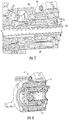
FIG. 5 is a perspective, cross-sectional view of a generator of the electrical power generation system; -
FIG. 6 is an enlarged view of the generator ofFIG. 5 ; and -
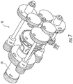
FIG. 7 is a perspective view of a gear reduction arrangement operatively coupling a turbine and the generator of the electrical power generation system. - Referring to
FIGS. 1 and 2 , embodiments of a directed energy weapon are illustrated. In the illustrated embodiments, the directed energy weapon comprises a directedenergy system 10 that facilitates generation of a directed energy weapon, such as alaser beam 12, onboard avehicle 14 and guided control of thelaser beam 12 away from thevehicle 14. The directedenergy system 10 is beneficial in numerous applications, such as tactical weaponry, for example. As such, the embodiments described herein are advantageously operated on vehicles that require operation in environments which do not have atmospheric oxygen (i.e., oxygen gas) present. For example, thevehicle 14 may be a spacecraft (FIG. 1 ) or a high altitude aircraft (FIG. 2 ). Additionally, thevehicle 14 may be an undersea vessel that is completely submerged in fluid, such that oxygen gas is not readily available from the surrounding environment. - Although a
laser beam 12 is illustrated and referenced herein, it is to be appreciated that the electricity generated by an electrical power generation system 20 (discussed in detail herein) could be used for other directed energy weapons, such as high power microwaves, high power radars, radar jammers, and electromagnetic rail guns. - The directed
energy system 10 includes a laser generating assembly located onboard thevehicle 14. The location of the laser generating assembly may vary depending upon the particular embodiment of thevehicle 14. The laser generating assembly includes a plurality of components and subassemblies that in conjunction generate thelaser beam 12. Such components relate to power management, weapons targeting, aircraft integration, laser module(s) and thermal cooling, for example. The preceding list is merely illustrative and not intended to be limiting. Irrespective of the precise components of the laser generating assembly, the generatedlaser beam 12 is routed along a laser carrying component to alaser turret 16 for transmission of thelaser beam 12 away from thevehicle 14 to a target. The laser carrying component is operatively coupled to thelaser turret 16 and the laser generating assembly. It is to be appreciated that a plurality of laser carrying components may be included to provide multiple laser paths, which may lead to a single laser turret or a plurality of laser turrets. - The directed
energy system 10 requires significant power to maintain operation for an extended period of time. As shown inFIGS. 3 and4 , an electricalpower generation system 20 is provided to generate and supply electrical power for the directedenergy system 10. The electricalpower generation system 20 is located onboard thevehicle 14 at any suitable location. By way of non-limiting example, in the case of a high altitude aircraft, the electricalpower generation system 20 may be mounted in an underwing pod or in an aircraft fuselage. As will be appreciated from the description herein, the electricalpower generation system 20 provides a high power density and its form factor is well suited for compact placement at desired locations of thevehicle 14. - The electrical
power generation system 20 includes aturbine engine 22 that is operatively coupled to agenerator 40 in order to generate electrical power to be supplied to the directedenergy system 10. Theturbine engine 22 includes at least onestage 26 of turbine blades operatively coupled to aturbine rotor 28. Thestage 26 of turbine blades are rotated in response to a hot gas combustion mixture that passes over the blades subsequent to combustion in acombustor 30. Thecombustor 30 is supplied a liquid fuel with a fuel pump 32 and is supplied a liquid oxidant with anoxidizer pump 34. The liquid fuel and the liquid oxidant are mixed within thecombustor 30 for combustion therein. - A
coolant pump 36 is included in some embodiments to provide a coolant (e.g., water) to thecombustor 30 during operation. Thecoolant pump 36 also provides lubrication and coolant to the rest of theturbine engine 22 andgenerator 40, as needed. Providing coolant to thecombustor 30 reduces the flame temperature within thecombustor 30 to reduce the likelihood of damage to turbine components, such as the turbine blades. Additionally, the coolant flashes off to steam in the case of water, which has a high molecular weight, providing additional fluid dynamic energy to the turbine blades, which increases the mechanical output of theturbine 22. - In an alternate embodiment, rather than the
coolant pump 36, the electricalpower generation system 20 may be configured to condense water generated in the combustor 30 (steam is a product produced from the fuel-oxidizer reaction itself) through a heat exchanger. The water may then be pumped and injected into thecombustor 30 again to cool down the combustion temperature. Such an embodiment advantageously eliminates the added weight of carrying a water reservoir onboard thevehicle 14. - As noted above, the resultant combustion mixture is routed to the turbine to covert the chemical energy of the combustion mixture to mechanical energy in the form of rotation of the turbine blades and the
turbine rotor 28. The liquid oxidant stored onboard thevehicle 14 alleviates the issue of not having readily available air, including atmospheric oxygen gas, that is typically ingested into a compressor and subsequently mixed with fuel in a combustor. Illustrative examples of liquid oxidants that may be employed include nitrous oxide, hydrogen peroxide, and liquid oxygen, however, it is to be understood that suitable alternative are contemplated. Therefore, theturbine engine 22 is a bi-propellant turbo system that relies solely on a liquid fuel and a liquid oxidant, both of which are stored onboard thevehicle 14. - Referring now to
FIGS. 5 and 6 , with continued reference toFIGS. 3 and4 , theturbine rotor 28 is operatively coupled to agenerator 40. Thegenerator 40 converts the mechanical power of therotating turbine rotor 28 into electrical power based on the interaction of theturbine rotor 28 and thegenerator 40. Thegenerator 40 may be any suitable generator that may be stored onboard thevehicle 14 under the operating conditions of the vehicle. For example, thegenerator 40 may be a permanent magnet generator, a wound field generator, a switch reluctance generator, an inductance generator and a hybrid generator. The preceding list is merely exemplary and is not limiting of the type of generator to be employed. In some embodiments, thegenerator 40 is a 1 MW generator, but other power ratings are contemplated and the power rating will depend upon the particular application. Irrespective of the precise type of generator, thegenerator 40 includes agenerator rotor 42 operatively coupled to theturbine rotor 28. Rotation of thegenerator rotor 42 interacts with astator 44 to generate electrical power that is harnessed and selectively supplied to the directedenergy system 10. - In some embodiments, it is desirable to manipulate the rotational output speed of the
turbine rotor 28 in order to reduce the output speed to a speed that is suitable for thegenerator 40. In such embodiments, agear reduction arrangement 50 is provided, as shown inFIG. 7 . Thegear reduction arrangement 50 is illustrated with a particular number of gears and shafts, but it is to be appreciated that the precise number of gears and shafts will depend upon the particular application and the necessary speed reduction. In one embodiment, the speed may be reduced from about 60,000 rpm to about 17,000 rpm. - Advantageously, the ability to combine a liquid fuel with a liquid oxidant gives the bi-propellant turbo-generator the ability to operate at extremely high altitudes or undersea, where atmospheric oxygen is not readily available.
- While the disclosure has been described in detail in connection with only a limited number of embodiments, it should be readily understood that the disclosure is not limited to such disclosed embodiments. Rather, the disclosure can be modified to incorporate any number of variations, alterations, substitutions or equivalent arrangements not heretofore described, but which are commensurate with the scope of the disclosure. Additionally, while various embodiments of the disclosure have been described, it is to be understood that aspects of the disclosure may include only some of the described embodiments. Accordingly, the disclosure is not to be seen as limited by the foregoing description, but is only limited by the scope of the appended claims.
Claims (15)
- An electrical power generation system for a directed energy weapon comprising:a fuel pump (32) configured to disperse a liquid fuel;an oxidizer pump (34) configured to disperse a liquid oxidant;a combustor (30) fluidly coupled to the fuel pump and the oxidizer pump to receive the liquid fuel and the liquid oxidant for combustion therein to form a combustion mixture;a turbine (22) fluidly coupled to the combustor to receive the combustion mixture to generate mechanical energy; anda generator (40) operatively coupled to a rotor shaft of the turbine to convert the mechanical energy to electrical power for the directed energy weapon.
- The electrical power generation system of claim 1, further comprising a gear reduction arrangement (50) operatively coupled to a rotor shaft of the turbine and a generator rotor (42).
- The electrical power generation system of any preceding claim, wherein the generator is one of a permanent magnet generator, a wound field generator, a switch reluctance generator, an induction generator, and a hybrid generator.
- The electrical power generation system of any preceding claim, further comprising a coolant pump (36) configured to disperse a coolant to the combustor.
- The electrical power generation system of claim 4, wherein the coolant comprises water.
- The electrical power generation system of any preceding claim, wherein the liquid oxidant comprises nitrous oxide.
- The electrical power generation system of any of claims 1 to 5, wherein the liquid oxidant comprises liquid oxygen.
- The electrical power generation system of any preceding claim, wherein the electrical power generation system is disposed on a high altitude aircraft (14).
- The electrical power generation system of any of claims 1 to 7, wherein the electrical power generation system is disposed on an undersea application.
- The electrical power generation system of any preceding claim, wherein the directed energy weapon comprises at least one of a laser beam, high power microwaves, high power radars, radar jammers and electromagnetic rail guns.
- A method of generating electrical power for a directed energy weapon comprising:pumping a liquid fuel to a combustor;pumping a liquid oxidant to the combustor for combustion therein to form a combustion mixture;routing the combustion mixture to a turbine to convert thermal energy of the combustion mixture to mechanical energy; andconverting the mechanical energy to electrical power with a generator operatively coupled to a rotor shaft of the turbine.
- The method of claim 11, wherein the power generation is performed in an atmosphere that does not have atmospheric oxygen present.
- The method of claim 12, wherein the power generation is performed on a high altitude aircraft.
- The method of claim 12, wherein the power generation is performed on an undersea application.
- The method of any of claims 11 to 14, further comprising injecting at least one of coolant and recycled combustion products into the combustor.
Applications Claiming Priority (1)
| Application Number | Priority Date | Filing Date | Title |
|---|---|---|---|
| US15/000,505 US20180252115A1 (en) | 2016-01-19 | 2016-01-19 | Electrical power generation system for a directed energy weapon and method |
Publications (1)
| Publication Number | Publication Date |
|---|---|
| EP3196440A1 true EP3196440A1 (en) | 2017-07-26 |
Family
ID=57860672
Family Applications (1)
| Application Number | Title | Priority Date | Filing Date |
|---|---|---|---|
| EP17151675.0A Withdrawn EP3196440A1 (en) | 2016-01-19 | 2017-01-16 | Electrical power generation system for a directed energy weapon and method |
Country Status (2)
| Country | Link |
|---|---|
| US (1) | US20180252115A1 (en) |
| EP (1) | EP3196440A1 (en) |
Families Citing this family (7)
| Publication number | Priority date | Publication date | Assignee | Title |
|---|---|---|---|---|
| US10263552B2 (en) * | 2017-08-08 | 2019-04-16 | Rolls-Royce North American Technologies Inc. | Anticipatory control using output shaft speed |
| EP3931091B1 (en) | 2019-03-01 | 2025-10-29 | Pratt & Whitney Canada Corp. | Distributed propulsion configurations for aircraft having mixed drive systems |
| US11732639B2 (en) | 2019-03-01 | 2023-08-22 | Pratt & Whitney Canada Corp. | Mechanical disconnects for parallel power lanes in hybrid electric propulsion systems |
| US11628942B2 (en) | 2019-03-01 | 2023-04-18 | Pratt & Whitney Canada Corp. | Torque ripple control for an aircraft power train |
| CA3132285A1 (en) | 2019-03-01 | 2020-09-10 | Pratt & Whitney Canada Corp. | Torque balancing for hybrid electric propulsion systems and aircraft utilizing hybrid electric propulsion systems |
| EP3941830B1 (en) | 2019-03-18 | 2024-11-06 | Pratt & Whitney Canada Corp. | Architectures for hybrid-electric propulsion |
| US11486472B2 (en) | 2020-04-16 | 2022-11-01 | United Technologies Advanced Projects Inc. | Gear sytems with variable speed drive |
Citations (7)
| Publication number | Priority date | Publication date | Assignee | Title |
|---|---|---|---|---|
| US3134228A (en) * | 1961-07-27 | 1964-05-26 | Thompson Ramo Wooldridge Inc | Propulsion system |
| US3972180A (en) * | 1971-09-21 | 1976-08-03 | Chicago Bridge & Iron Company | High pressure reactor with turbo expander |
| US4147025A (en) * | 1973-11-02 | 1979-04-03 | Vereinigte Flugtechnische Werke-Fokker Gmbh | Formation of auxiliary drive gas for turbine |
| US4945811A (en) * | 1988-04-28 | 1990-08-07 | Mtu Motoren- Und Turbinen-Union Munchen Gmbh | Weapon system |
| US20070051233A1 (en) * | 2005-09-06 | 2007-03-08 | Duge Robert T | Radiant electromagnetic energy management |
| WO2009005479A1 (en) * | 2007-06-29 | 2009-01-08 | Ivan Kocis | Equipment for excavation of deep boreholes in geological formation and the manner of energy and material transport in the boreholes |
| US20110126549A1 (en) * | 2006-01-13 | 2011-06-02 | Pronske Keith L | Ultra low emissions fast starting power plant |
Family Cites Families (4)
| Publication number | Priority date | Publication date | Assignee | Title |
|---|---|---|---|---|
| US1421435A (en) * | 1919-03-24 | 1922-07-04 | fauchon-villeplee | |
| US20070183783A1 (en) * | 2006-02-07 | 2007-08-09 | Raytheon Company | Netted communication and weapons system for littoral warfare |
| EP2084394A4 (en) * | 2006-11-13 | 2013-06-19 | Space Propulsion Group Inc | Mixtures of oxides of nitrogen and oxygen as oxidizers for propulsion, gas generation and power generation applications |
| US8148866B2 (en) * | 2008-06-27 | 2012-04-03 | Hamilton Sundstrand Corporation | Regulated hybrid permanent magnet generator |
-
2016
- 2016-01-19 US US15/000,505 patent/US20180252115A1/en not_active Abandoned
-
2017
- 2017-01-16 EP EP17151675.0A patent/EP3196440A1/en not_active Withdrawn
Patent Citations (7)
| Publication number | Priority date | Publication date | Assignee | Title |
|---|---|---|---|---|
| US3134228A (en) * | 1961-07-27 | 1964-05-26 | Thompson Ramo Wooldridge Inc | Propulsion system |
| US3972180A (en) * | 1971-09-21 | 1976-08-03 | Chicago Bridge & Iron Company | High pressure reactor with turbo expander |
| US4147025A (en) * | 1973-11-02 | 1979-04-03 | Vereinigte Flugtechnische Werke-Fokker Gmbh | Formation of auxiliary drive gas for turbine |
| US4945811A (en) * | 1988-04-28 | 1990-08-07 | Mtu Motoren- Und Turbinen-Union Munchen Gmbh | Weapon system |
| US20070051233A1 (en) * | 2005-09-06 | 2007-03-08 | Duge Robert T | Radiant electromagnetic energy management |
| US20110126549A1 (en) * | 2006-01-13 | 2011-06-02 | Pronske Keith L | Ultra low emissions fast starting power plant |
| WO2009005479A1 (en) * | 2007-06-29 | 2009-01-08 | Ivan Kocis | Equipment for excavation of deep boreholes in geological formation and the manner of energy and material transport in the boreholes |
Also Published As
| Publication number | Publication date |
|---|---|
| US20180252115A1 (en) | 2018-09-06 |
Similar Documents
| Publication | Publication Date | Title |
|---|---|---|
| US20180252115A1 (en) | Electrical power generation system for a directed energy weapon and method | |
| US8857192B2 (en) | Accessory gearbox with a starter/generator | |
| US10358977B2 (en) | Phase change material cooling system for a vehicle | |
| US7224082B2 (en) | Turbomachine including an integrated electricity generator | |
| US10637326B2 (en) | Variable gear ratio electrical machine | |
| US10794271B2 (en) | Altitude augmentation system | |
| US10894607B2 (en) | Drive system for a vehicle with an internal combustion engine and fuel tank | |
| US10119414B2 (en) | Hafnium turbine engine and method of operation | |
| US20180363564A1 (en) | Hybrid power or thrust generator and vehicle including such a generator | |
| EP4012169A1 (en) | Method of operating an aircraft engine and fuel system using multiple fuel types | |
| US12024302B2 (en) | Hybrid starter motor-generator | |
| US10480408B2 (en) | Energy weapon system having a gas turbine generator with idle assist | |
| GB2594072A (en) | Hybrid aircraft propulsion system | |
| JP5070163B2 (en) | Engine with intake air temperature control system | |
| Green et al. | Analysis of a distributed hybrid propulsion system with conventional electric machines | |
| CA2895711A1 (en) | Turbine engine assembly and dual fuel aircraft system | |
| RU2545615C1 (en) | Liquid-propellant rocket engine turbo pump unit | |
| Mane | Advancements in gas turbine engine technology: A conceptual aspect | |
| US12152534B2 (en) | Systems and methods for propulsion | |
| Sayma | Gas turbines for marine applications | |
| US10266277B2 (en) | Method and system for optimized production of non-propulsive energy | |
| RU2686815C1 (en) | Nuclear turbojet | |
| Klaass et al. | The quest for oil-free gas turbine engines | |
| US20180106219A1 (en) | Propulsion system | |
| Pifer | Modeling of the electric ship |
Legal Events
| Date | Code | Title | Description |
|---|---|---|---|
| PUAI | Public reference made under article 153(3) epc to a published international application that has entered the european phase |
Free format text: ORIGINAL CODE: 0009012 |
|
| STAA | Information on the status of an ep patent application or granted ep patent |
Free format text: STATUS: THE APPLICATION HAS BEEN PUBLISHED |
|
| AK | Designated contracting states |
Kind code of ref document: A1 Designated state(s): AL AT BE BG CH CY CZ DE DK EE ES FI FR GB GR HR HU IE IS IT LI LT LU LV MC MK MT NL NO PL PT RO RS SE SI SK SM TR |
|
| AX | Request for extension of the european patent |
Extension state: BA ME |
|
| STAA | Information on the status of an ep patent application or granted ep patent |
Free format text: STATUS: REQUEST FOR EXAMINATION WAS MADE |
|
| 17P | Request for examination filed |
Effective date: 20180126 |
|
| RBV | Designated contracting states (corrected) |
Designated state(s): AL AT BE BG CH CY CZ DE DK EE ES FI FR GB GR HR HU IE IS IT LI LT LU LV MC MK MT NL NO PL PT RO RS SE SI SK SM TR |
|
| STAA | Information on the status of an ep patent application or granted ep patent |
Free format text: STATUS: EXAMINATION IS IN PROGRESS |
|
| STAA | Information on the status of an ep patent application or granted ep patent |
Free format text: STATUS: THE APPLICATION HAS BEEN WITHDRAWN |
|
| 17Q | First examination report despatched |
Effective date: 20210127 |
|
| 18W | Application withdrawn |
Effective date: 20210209 |