EP3196353A1 - Steel cord for reinforcing rubber article - Google Patents
Steel cord for reinforcing rubber article Download PDFInfo
- Publication number
- EP3196353A1 EP3196353A1 EP15827718.6A EP15827718A EP3196353A1 EP 3196353 A1 EP3196353 A1 EP 3196353A1 EP 15827718 A EP15827718 A EP 15827718A EP 3196353 A1 EP3196353 A1 EP 3196353A1
- Authority
- EP
- European Patent Office
- Prior art keywords
- sheath
- filaments
- outermost layer
- cord
- core strand
- Prior art date
- Legal status (The legal status is an assumption and is not a legal conclusion. Google has not performed a legal analysis and makes no representation as to the accuracy of the status listed.)
- Granted
Links
Images
Classifications
-
- B—PERFORMING OPERATIONS; TRANSPORTING
- B60—VEHICLES IN GENERAL
- B60C—VEHICLE TYRES; TYRE INFLATION; TYRE CHANGING; CONNECTING VALVES TO INFLATABLE ELASTIC BODIES IN GENERAL; DEVICES OR ARRANGEMENTS RELATED TO TYRES
- B60C9/00—Reinforcements or ply arrangement of pneumatic tyres
- B60C9/0007—Reinforcements made of metallic elements, e.g. cords, yarns, filaments or fibres made from metal
-
- B—PERFORMING OPERATIONS; TRANSPORTING
- B60—VEHICLES IN GENERAL
- B60C—VEHICLE TYRES; TYRE INFLATION; TYRE CHANGING; CONNECTING VALVES TO INFLATABLE ELASTIC BODIES IN GENERAL; DEVICES OR ARRANGEMENTS RELATED TO TYRES
- B60C9/00—Reinforcements or ply arrangement of pneumatic tyres
-
- D—TEXTILES; PAPER
- D07—ROPES; CABLES OTHER THAN ELECTRIC
- D07B—ROPES OR CABLES IN GENERAL
- D07B1/00—Constructional features of ropes or cables
- D07B1/06—Ropes or cables built-up from metal wires, e.g. of section wires around a hemp core
-
- D—TEXTILES; PAPER
- D07—ROPES; CABLES OTHER THAN ELECTRIC
- D07B—ROPES OR CABLES IN GENERAL
- D07B1/00—Constructional features of ropes or cables
- D07B1/06—Ropes or cables built-up from metal wires, e.g. of section wires around a hemp core
- D07B1/0606—Reinforcing cords for rubber or plastic articles
- D07B1/0613—Reinforcing cords for rubber or plastic articles the reinforcing cords being characterised by the rope configuration
-
- D—TEXTILES; PAPER
- D07—ROPES; CABLES OTHER THAN ELECTRIC
- D07B—ROPES OR CABLES IN GENERAL
- D07B1/00—Constructional features of ropes or cables
- D07B1/06—Ropes or cables built-up from metal wires, e.g. of section wires around a hemp core
- D07B1/0606—Reinforcing cords for rubber or plastic articles
- D07B1/062—Reinforcing cords for rubber or plastic articles the reinforcing cords being characterised by the strand configuration
-
- B—PERFORMING OPERATIONS; TRANSPORTING
- B60—VEHICLES IN GENERAL
- B60C—VEHICLE TYRES; TYRE INFLATION; TYRE CHANGING; CONNECTING VALVES TO INFLATABLE ELASTIC BODIES IN GENERAL; DEVICES OR ARRANGEMENTS RELATED TO TYRES
- B60C9/00—Reinforcements or ply arrangement of pneumatic tyres
- B60C2009/0071—Reinforcements or ply arrangement of pneumatic tyres characterised by special physical properties of the reinforcements
- B60C2009/0092—Twist structure
-
- B—PERFORMING OPERATIONS; TRANSPORTING
- B60—VEHICLES IN GENERAL
- B60C—VEHICLE TYRES; TYRE INFLATION; TYRE CHANGING; CONNECTING VALVES TO INFLATABLE ELASTIC BODIES IN GENERAL; DEVICES OR ARRANGEMENTS RELATED TO TYRES
- B60C9/00—Reinforcements or ply arrangement of pneumatic tyres
- B60C9/18—Structure or arrangement of belts or breakers, crown-reinforcing or cushioning layers
-
- B—PERFORMING OPERATIONS; TRANSPORTING
- B60—VEHICLES IN GENERAL
- B60C—VEHICLE TYRES; TYRE INFLATION; TYRE CHANGING; CONNECTING VALVES TO INFLATABLE ELASTIC BODIES IN GENERAL; DEVICES OR ARRANGEMENTS RELATED TO TYRES
- B60C9/00—Reinforcements or ply arrangement of pneumatic tyres
- B60C9/18—Structure or arrangement of belts or breakers, crown-reinforcing or cushioning layers
- B60C9/20—Structure or arrangement of belts or breakers, crown-reinforcing or cushioning layers built-up from rubberised plies each having all cords arranged substantially parallel
-
- D—TEXTILES; PAPER
- D07—ROPES; CABLES OTHER THAN ELECTRIC
- D07B—ROPES OR CABLES IN GENERAL
- D07B1/00—Constructional features of ropes or cables
- D07B1/06—Ropes or cables built-up from metal wires, e.g. of section wires around a hemp core
- D07B1/0606—Reinforcing cords for rubber or plastic articles
- D07B1/062—Reinforcing cords for rubber or plastic articles the reinforcing cords being characterised by the strand configuration
- D07B1/0626—Reinforcing cords for rubber or plastic articles the reinforcing cords being characterised by the strand configuration the reinforcing cords consisting of three core wires or filaments and at least one layer of outer wires or filaments, i.e. a 3+N configuration
-
- D—TEXTILES; PAPER
- D07—ROPES; CABLES OTHER THAN ELECTRIC
- D07B—ROPES OR CABLES IN GENERAL
- D07B1/00—Constructional features of ropes or cables
- D07B1/06—Ropes or cables built-up from metal wires, e.g. of section wires around a hemp core
- D07B1/0606—Reinforcing cords for rubber or plastic articles
- D07B1/062—Reinforcing cords for rubber or plastic articles the reinforcing cords being characterised by the strand configuration
- D07B1/0633—Reinforcing cords for rubber or plastic articles the reinforcing cords being characterised by the strand configuration having a multiple-layer configuration
-
- D—TEXTILES; PAPER
- D07—ROPES; CABLES OTHER THAN ELECTRIC
- D07B—ROPES OR CABLES IN GENERAL
- D07B2201/00—Ropes or cables
- D07B2201/20—Rope or cable components
- D07B2201/2001—Wires or filaments
- D07B2201/2006—Wires or filaments characterised by a value or range of the dimension given
-
- D—TEXTILES; PAPER
- D07—ROPES; CABLES OTHER THAN ELECTRIC
- D07B—ROPES OR CABLES IN GENERAL
- D07B2201/00—Ropes or cables
- D07B2201/20—Rope or cable components
- D07B2201/2015—Strands
- D07B2201/2024—Strands twisted
- D07B2201/2029—Open winding
-
- D—TEXTILES; PAPER
- D07—ROPES; CABLES OTHER THAN ELECTRIC
- D07B—ROPES OR CABLES IN GENERAL
- D07B2201/00—Ropes or cables
- D07B2201/20—Rope or cable components
- D07B2201/2015—Strands
- D07B2201/2036—Strands characterised by the use of different wires or filaments
- D07B2201/2037—Strands characterised by the use of different wires or filaments regarding the dimension of the wires or filaments
-
- D—TEXTILES; PAPER
- D07—ROPES; CABLES OTHER THAN ELECTRIC
- D07B—ROPES OR CABLES IN GENERAL
- D07B2201/00—Ropes or cables
- D07B2201/20—Rope or cable components
- D07B2201/2047—Cores
- D07B2201/2051—Cores characterised by a value or range of the dimension given
-
- D—TEXTILES; PAPER
- D07—ROPES; CABLES OTHER THAN ELECTRIC
- D07B—ROPES OR CABLES IN GENERAL
- D07B2201/00—Ropes or cables
- D07B2201/20—Rope or cable components
- D07B2201/2047—Cores
- D07B2201/2052—Cores characterised by their structure
- D07B2201/2059—Cores characterised by their structure comprising wires
- D07B2201/2061—Cores characterised by their structure comprising wires resulting in a twisted structure
-
- D—TEXTILES; PAPER
- D07—ROPES; CABLES OTHER THAN ELECTRIC
- D07B—ROPES OR CABLES IN GENERAL
- D07B2401/00—Aspects related to the problem to be solved or advantage
- D07B2401/20—Aspects related to the problem to be solved or advantage related to ropes or cables
- D07B2401/208—Enabling filler penetration
Definitions
- a pneumatic tire of the present invention is characterized in that the steel cord for reinforcing a rubber article of the present invention is used as a reinforcing material.
Landscapes
- Engineering & Computer Science (AREA)
- Mechanical Engineering (AREA)
- Ropes Or Cables (AREA)
- Tires In General (AREA)
Abstract
Description
- The present invention relates to a steel cord for reinforcing a rubber article (hereinafter, also simply referred to as "cord"), and particularly to a steel cord for reinforcing a rubber article for use in reinforcing applications for rubber articles such as tires.
- For a rubber article such as a tire, a steel cord formed by twisting a plurality of steel filaments is widely used as a reinforcing material. In particular, since a tire used for a heavy duty vehicle such as a construction vehicle is used under heavy loading on rough terrain having sharp rises or drops or the like, a steel cord to be used as a reinforcing material is demanded to have a particularly high strength and resistance. For this reason, in such a large tire, a steel cord having a so-called multi-twisted structure, which is formed by twisting a plurality of strands formed by twisting a plurality of steel filaments, is employed.
- As a prior art relating to a steel cord having a multi-twisted structure, for example,
Patent Document 1 discloses a steel cord constituted in such a manner that, in order to surely allow rubber penetrate to the inside of the cord having a multi-twisted structure, around one core strand composed of a plurality of filaments, five sheath strands having the same diameter as that of the core strand, each composed of a plurality of filaments, are twisted. - Patent Document 1:
Japanese Unexamined Patent Application Publication No. 2001-11784 - In a steel cord used for reinforcing a tire, from the viewpoint of preventing the occurrence of rust, preferably, rubber sufficiently fills a space between filaments constituting the cord, and so-called rubber penetrability (rubber permeability) is favorable. However, in a cord having a multi-twisted structure, since the number of filaments is large and the twisted structure is complicated, in order to achieve sufficient rubber penetrability to obtain a desired rust prevention property, the strength and the shear resistance of the cord have had to be sacrificed.
- Accordingly, an object of the present invention is to provide a steel cord for reinforcing a rubber article in which, in a cord having a multi-twisted structure, both the rubber penetrability (rust prevention), and the cord strength and shear resistance are highly achieved by appropriately balancing the cord structure and the amount of clearance between filaments constituting the cord.
- The present inventor intensively studied to find that the above-described problems can be solved by employing the following configuration, thereby completing the present invention.
- That is, the steel cord for reinforcing a rubber article of the present invention is a steel cord for reinforcing a rubber article comprising: one core strand having a layered-twisted structure formed by twisting a plurality of steel filaments; and a plurality of sheath strands having a layered-twisted structure formed by twisting a plurality of steel filaments, wherein the sheath strands are twisted around the core strand, and
wherein an average value Lc of an amount of clearance between outermost layer sheath filaments constituting an outermost layer sheath of the core strand is from 0.073 to 0.130 mm, and the number of the outermost layer sheath filaments is from 7 to 10. - In the cord of the present invention, preferably, the number of the sheath strands is from 7 to 9. In the cord of the present invention, preferably, all filaments constituting the core strand have the same diameter. Further, in the cord of the present invention, preferably, a cord diameter is not less than 5.00 mm.
- Still further, in the cord of the present invention, preferably, the ratio Lc/Ls of the average value Lc of the amount of clearance between the outermost layer sheath filaments constituting the outermost layer sheath of the core strand to an average value Ls of an amount of clearance between outermost layer sheath filaments constituting an outermost layer sheath of the sheath strand is more than 1 and not more than 1.5. Still further, in the cord of the present invention, preferably, the core strand has a two-layered structure.
- A pneumatic tire of the present invention is characterized in that the steel cord for reinforcing a rubber article of the present invention is used as a reinforcing material.
- According to the present invention, it becomes possible to realize a steel cord for reinforcing a rubber article in which both the rubber penetrability (rust prevention), and the cord strength and shear resistance are highly achieved.
-
-
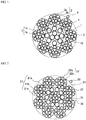
FIG. 1 is a cross-sectional view in the width direction illustrating one configuration example of a steel cord for reinforcing a rubber article of the present invention. -
FIG. 2 is a cross-sectional view in the width direction illustrating another configuration example of a steel cord for reinforcing a rubber article of the present invention. - Hereinafter, embodiments of the present invention will be described in detail with reference to the drawing.
-
FIG. 1 and FIG.2 are a cross-sectional view in the width direction illustrating one configuration example of a steel cord for reinforcing a rubber article of the present invention. The cord illustrated inFIG. 1 comprises: onecore strand 11 having a two-layered layered-twisted structure formed by twisting a plurality ofsteel filaments 1; and a plurality of (in the illustrated example, eight)sheath strands 12 each having two-layered layered-twisted structure formed by twisting a plurality ofsteel filaments 2, and has a multi-twisted structure formed by twisting thesheath strands 12 around thecore strand 11. In the illustrated cord, thecore strand 11 has a 3+8 structure in which a sheath is formed by twisting eightsheath filaments 1b around a core composed of twisted threecore filaments 1a, and thesheath strand 12 has a 3+8 structure in which a sheath is formed by twisting eightsheath filaments 2b around a core composed of twisted threecore filaments 2a. In the illustrated cord, aspiral filament 3 is spirally wound around the outer periphery of thesheath strand 12. - The cord illustrated in
FIG. 2 comprises: onecore strand 31 having a three-layered layered-twisted structure formed by twisting a plurality ofsteel filaments 21; and a plurality of (in the illustrated example, eight)sheath strands 32 each having two-layered layered-twisted structure formed by twisting a plurality ofsteel filaments 22, and has a multi-twisted structure formed by twisting thesheath strands 32 around thecore strand 31. In the illustrated cord, thecore strand 31 has a 3+8+10 structure in which a first sheath is formed by twisting eightsheath filaments 21b around a core composed of twisted threecore filaments 21a, and a second sheath is formed by twisting tensecond sheath filaments 21c therearound, and thesheath strand 32 has a 3+8 structure in which a sheath is formed by twisting eightsheath filaments 22b around a core composed of twisted threecore filaments 22a. In the illustrated cord, aspiral filament 23 is spirally wound around the outer periphery of thesheath strand 32. - In the present invention, it is important that the average value Lc of the amount of clearance between the outermost
layer sheath filaments core strands layer sheath filaments - Here, in the present invention, the average value Lc of the amount of clearance between the outermost layer sheath filaments of the core strand is a calculated value obtained by dividing the value obtained by subtracting the sum of the diameters of the outermost layer filaments constituting the strand from the perimeter of the virtual circle or the ellipse passing through the center points of all the outermost layer filaments constituting the strand, by the number of the outermost layer filaments constituting the strand. The average value Lc of the amount of clearance between the outermost layer sheath filaments needs to be from 0.073 to 0.130 mm, and is preferably from 0.100 to 0.110 mm. When the average value Lc of the amount of clearance between the outermost layer sheath filaments is less than 0.073 mm, sufficient rust prevention is not obtained, and when the average value exceeds 0.130 mm, sufficient cord strength and shear resistance are not obtained.
- In the present invention, The ratio Lc / Ls of the average value Lc of the amount of clearance between the outermost layer sheath filaments constituting the outermost layer sheath of the core strand to the average value Ls of the clearance amount between the outermost layer sheath filaments constituting the outermost layer sheath of the sheath strand is preferably more than 1 and not more than 1.5, and more preferably from 1.25 to 1.42. Rubber is less likely to penetrate the core strand located at the center of the cord than the sheath strand located therearound, and therefore, from the viewpoint of further improving the rust prevention, it is preferable that the average value of the amount of clearance between the outermost layer sheath filaments is larger in the core strand than the sheath strand. Here, the average value Ls of the amount of clearance between the outermost layer sheath filaments of the sheath strand is a value obtained in a similar manner to the average value Lc of the amount of clearance between the outermost layer sheath filaments of the core strand.
- In the cord of the present invention, the number of layers of the layered-twisted structure of the core strand is not particularly limited, and may be, for example, from 2 to 3. In this case, assuming that a first sheath and a second sheath are sequentially formed from the inner layer of the layered-twisted structure, when the
core strand 11 has a two-layered layered-twisted structure as illustrated inFIG. 1 , the outermost layer sheath of thecore strand 11 is the first sheath, and when thecore strand 31 has a three-layered layered-twisted structure as illustrated inFIG. 2 , the outermost layer sheath of thecore strand 31 is the second sheath. The number of layers of the layered-twisted structure of the sheath strand is not particularly limited, and may be, for example, from 2 to 3. In this case, similarly to the case of the core strand, when thesheath strand FIG. 1 and FIG. 2 , the outermost layer sheath of thesheath strand - In the cord of the present invention, the number of the
sheath strand 12 is preferably from 7 to 9. When all the core strand and sheath strands have the same diameter and the sheath strands are close-packed without a gap therebetween, six sheath strands can be arranged. However, as illustrated in the drawing, in the present invention, since the diameter of thesheath strand 12 is smaller than that of thecore strand 11, seven to ninesheath strands 12 can be arranged. Accordingly, by setting the number of thesheath strands 12 to from 7 to 9, it is possible to further improve the resistance of the core strand to the tightening force of the sheath strand, and to further improve the cut resistance of the cord. - In the cord of the present invention, as illustrated in
FIG. 1 , when the core strand has a two-layered structure, it is preferable that all thefilaments 1 constituting thecore strand 11 have the same diameter. It is possible to improve the shear resistance by making thecore filament 1a smaller in diameter than thesheath filament 1b in thecore strand 11. In this case, however, it is difficult to ensure sufficient amount of clearance between the sheath filaments. Accordingly, when the core strand has a two-layered structure, it is preferable that all thefilaments 1 constituting thecore strand 11 have the same diameter. Similarly, as illustrated inFIG. 2 , when the core strand has a three-layered structure, it is preferable that, among filaments constituting thecore strand 31, all ofcore filaments 21a andfirst sheath filaments 21b have the same diameter. When thecore filament 21a is made smaller in diameter than thefirst sheath filament 21b in thecore strand 31, it is difficult to ensure sufficient amount of clearance between first sheath filaments. Accordingly, when the core strand has a three-layered structure, it is preferable that all thecore filaments 21a andfirst sheath filaments 21b have the same diameter. - Further, the cord diameter of the cord of the present invention is preferably 5.00 mm or more, for example, from 5.00 to 6.00 mm. By using a cord having a diameter of 5.00 mm or more, it is possible to secure both strength and cut resistance required, particularly for large tires used for heavy duty vehicles such as construction vehicles.
- In the cord of the present invention, the wire diameter and tensile strength of the filament to be used, the twisting direction, the twisting pitch, and the like of the filament or strand are not particularly limited, and can be appropriately selected according to the ordinary method as desired. For example, as the filament, a so-called high tensile strength steel having a carbon content of 0.80% by mass or more can be used. The cord of the present invention may or may not include a spiral filament.
- Since the cord of the present invention is excellent in the rubber permeability, shear resistance, and strength, it is particularly suitable for a reinforcing material of large tires used for heavy duty vehicles such as construction vehicles, among others, ultra-large off-road radial tires having a tire size of about 40.00 R57. Such a large tire usually comprises: one or more carcasses composed of plies of steel cords extending in the radial direction between a pair of bead cores; at least four belt-crossing layers arranged radially outside the crown portion of the crown portion; and a tread disposed outside in the tire radial direction. The cord of the present invention can be used, for example, as a reinforcing cord for a belt crossing layer in such a tire.
- Hereinafter, the present invention will be described in more detail by way of examples.
- As shown in the following Tables, average values Lc and Ls of the amount of clearances between outermost layer sheath filaments constituting the outermost layer sheaths of a core strand and sheath strands were changed by changing the cord structure, to prepare steel cords for reinforcing a rubber article of Examples and Comparative Examples in which a plurality of sheath strands having a layered-twisted structure were twisted around one core strand having a layered-twisted structure. The results of the following evaluations for the obtained cords are also shown in the following Tables.
- For each obtained cord, the shear resistance was evaluated using a Charpy impact tester. The larger the numerical value is, the better the shear resistance is, which is favorable. A value was obtained by dividing the obtained shear resistance by the cross-sectional area of the cord, and the obtained value was indexed with Comparative Example 1 taken as 100. The larger the number is, the more favorable the cord is.
- The ratio of the rubber coated area to the surface area was measured for each cord (1) inside the outermost layer sheath filament of the core strand, (2) on the surface of the core strand, and (3) inside the outermost layer sheath filament of the sheath strand, and expressed as percentage (%). The larger the numerical value is, the better the rubber permeability is, which is favorable. In the results, indices with Comparative Example 1 taken as 100 were compared with each other. A larger number indicates that it is more favorable.
- The rust progression rate was measured for each cord (1) inside the outermost layer sheath filament of the core strand, (2) on the surface of the core strand, and (3) inside the outermost layer sheath filament of the sheath strand, and expressed as percentage (%). The smaller the numerical value is, the smaller the rust progression is, which is favorable. In the results, indices with Comparative Example 1 taken as 100 were compared with each other. A smaller number indicates that it is more favorable.
[Table 1] Comparative Example 1 Comparative Example 2 Comparative Example 3 Comparative Example 4 Example 1 Example 2 Cord structure (3+8×0.34)+ 6×(3+8× 0.34)+0.25 (3+6×0.465)+ 6×(3+8× 0.425)+0.25 (2+7×0.445)+ 6×(2+7× 0.445)+0.25 (3×0.54+11× 0.45)+7×(3+8 ×0.38)+0.25 (3+8×0.52)+ 7×(3+8× 0.395)+0.25 (3+8×0.53)+7 ×(3+8×0.39) +0.25 Core strand Number of outermost layer filaments 8 6 7 11 8 8 Average amount of clearance Lc (mm) between outermost layer filaments 0.07 0.268 0.134 0.005 0.108 0.11 Total amount of clearance (mm) between outermost layer filaments 0.56 1.608 0.938 0.055 0.864 0.88 Sheath strand Number of outermost layer filaments 8 8 7 8 8 8 Average amount of clearance Ls (mm) between outermost layer filaments 0.07 0.088 0.134 0.079 0.082 0.081 Total amount of clearance (mm) between outermost layer filaments 0.56 0.705 0.938 0.630 0.656 0.648 Lc/Ls 1.00 3.04 1.00 0.063 1.32 1.36 Cord diameter (mm) 4.24 5.46 5.34 5.22 5.44 5.44 Shear resistance /cord cross-sectional area (index)* 100 97 82 118 122 120 Rubber penetration rate (index)* 100 112 147 60 110 111 Rust progression rate (index)* 100 80 25 164 83 82 *) Values of "Shear resistance /cord cross-sectional area", "rubber penetration rate" and "rust progression rate" are all indexed with Comparative Example 1 taken as 100. The higher the numerical values of "Shear resistance / cord cross-sectional area" and "rubber penetration rate" are the more favorable. The lower the numerical value of "rust progression rate" is, the more favorable. [Table 2] Example 3 Example 4 Example 5 Example 6 Cord structure (3+8×0.54)+7×(3+ 8×0.385)+0.25 (3+8×0.51)+7 ×(3×0.380+8× 0.400)+0.25 (3+8×0.54)+8 ×(3×0.300+7× 0.365)+0.25 (3+8×0.56)+9 ×(1×0.50+6× 0.35)+0.25 Core strand Number of outermost layer filaments 8 8 8 8 Average amount of clearance Lc (mm) between outermost layer filaments 0.112 0.106 0.112 0.116 Total amount of clearance (mm) between outermost layer filaments 0.896 0.848 0.896 0.928 Sheath strand Number of outermost layer filaments 8 8 7 6 Average amount of clearance Ls (mm) between outermost layer filaments 0.08 0.066 0.074 0.075 Total amount of clearance (mm) between outermost layer filaments 0.64 0.531 0.517 0.45 Lc/Ls 1.40 1.61 1.51 1.55 Cord diameter (mm) 5.44 5.36 5.00 4.73 Shear resistance /cord cross-sectional area (index)* 117 108 112 110 Rubber penetration rate (index)* 112 102 113 113 Rust progression rate (index)* 80 97 79 79 - As can be seen from the results in the above Tables, in each of the cords of the Examples in which a plurality of sheath strands having a layered-twisted structure were twisted around one core strand having a layered-twisted structure, and the average value Lc of the amount of clearance between outermost layer sheath filaments of the core strand and the number of outermost layer sheath filaments satisfied predetermined conditions, it is obvious that both the rubber penetrability (rust prevention), and the cord strength and shear resistance are highly achieved.
-
- 1,2,21,22
- Steel filament
- 1a, 2a, 21a, 22a
- Core filament
- 1b
- Sheath filament (outermost layer sheath filament)
- 2b, 22b
- Sheath filament
- 3, 23
- Spiral filament
- 11, 31
- Core strand
- 12, 32
- Sheath strand
- 21b
- First sheath filament
- 21c
- Second sheath filament (outermost layer sheath filament)
Claims (7)
- A steel cord for reinforcing a rubber article comprising: one core strand having a layered-twisted structure formed by twisting a plurality of steel filaments; and a plurality of sheath strands having a layered-twisted structure formed by twisting a plurality of steel filaments, wherein the sheath strands are twisted around the core strand, and
wherein an average value Lc of an amount of clearance between outermost layer sheath filaments constituting an outermost layer sheath of the core strand is from 0.073 to 0.130 mm, and the number of the outermost layer sheath filaments is from 7 to 10. - The steel cord for reinforcing a rubber article according to claim 1, wherein the number of the sheath strands is from 7 to 9.
- The steel cord for reinforcing a rubber article according to claim 1, wherein all filaments constituting the core strand have the same diameter.
- The steel cord for reinforcing a rubber article according to claim 1, wherein a cord diameter is not less than 5.00 mm.
- The steel cord for reinforcing a rubber article according to claim 1, wherein the ratio Lc/Ls of the average value Lc of the amount of clearance between the outermost layer sheath filaments constituting the outermost layer sheath of the core strand to an average value Ls of an amount of clearance between outermost layer sheath filaments constituting an outermost layer sheath of the sheath strand is more than 1 and not more than 1.5.
- The steel cord for reinforcing a rubber article according to claim 1, wherein the core strand has a two-layered structure.
- A pneumatic tire, wherein the steel cord for reinforcing a rubber article according to claim 1 is used as a reinforcing material.
Applications Claiming Priority (2)
| Application Number | Priority Date | Filing Date | Title |
|---|---|---|---|
| JP2014153032 | 2014-07-28 | ||
| PCT/JP2015/071406 WO2016017654A1 (en) | 2014-07-28 | 2015-07-28 | Steel cord for reinforcing rubber article |
Publications (3)
| Publication Number | Publication Date |
|---|---|
| EP3196353A1 true EP3196353A1 (en) | 2017-07-26 |
| EP3196353A4 EP3196353A4 (en) | 2017-08-16 |
| EP3196353B1 EP3196353B1 (en) | 2018-09-12 |
Family
ID=55217553
Family Applications (1)
| Application Number | Title | Priority Date | Filing Date |
|---|---|---|---|
| EP15827718.6A Not-in-force EP3196353B1 (en) | 2014-07-28 | 2015-07-28 | Steel cord for reinforcing rubber article |
Country Status (6)
| Country | Link |
|---|---|
| US (1) | US10173470B2 (en) |
| EP (1) | EP3196353B1 (en) |
| JP (1) | JP6689747B2 (en) |
| CN (1) | CN106661831B (en) |
| ES (1) | ES2699885T3 (en) |
| WO (1) | WO2016017654A1 (en) |
Cited By (1)
| Publication number | Priority date | Publication date | Assignee | Title |
|---|---|---|---|---|
| EP3444127A4 (en) * | 2016-04-15 | 2019-04-10 | Bridgestone Corporation | Tire for construction vehicles, and steel cord |
Families Citing this family (5)
| Publication number | Priority date | Publication date | Assignee | Title |
|---|---|---|---|---|
| JP6545942B2 (en) | 2014-10-01 | 2019-07-17 | 株式会社ブリヂストン | Steel cord for reinforcing rubber articles and pneumatic tire using the same |
| CN110546324B (en) * | 2017-04-28 | 2022-02-18 | 株式会社普利司通 | Steel cord for reinforcing rubber article, method for producing same, and tire |
| JP6936059B2 (en) | 2017-06-30 | 2021-09-15 | 株式会社ブリヂストン | Steel cord for reinforcing rubber articles |
| JP6892374B2 (en) * | 2017-12-15 | 2021-06-23 | 株式会社ブリヂストン | Steel cords and tires for reinforcing rubber articles |
| FR3103500A1 (en) * | 2019-11-22 | 2021-05-28 | Compagnie Generale Des Etablissements Michelin | Two-layer multi-strand cable with improved surface fracture energy |
Family Cites Families (15)
| Publication number | Priority date | Publication date | Assignee | Title |
|---|---|---|---|---|
| JP3538205B2 (en) | 1992-03-09 | 2004-06-14 | 住友ゴム工業株式会社 | Steel cord for tire carcass, steel cord for tire filler, and tire using the same |
| JP3461043B2 (en) | 1994-09-12 | 2003-10-27 | 株式会社ブリヂストン | Steel cord for rubber article reinforcement |
| US5806296A (en) * | 1995-05-26 | 1998-09-15 | Bridgestone Metalpha Corporation | Corrosion resistant spiral steel filament and steel cord made therefrom |
| US5802829A (en) * | 1995-12-14 | 1998-09-08 | Bridgestone Corporation | Steel cords for reinforcing rubber articles and pneumatic radial tire using the steel cords |
| KR100296075B1 (en) | 1999-03-05 | 2001-07-03 | 조충환 | A rubber and a steel cord for reinforcement of a tire with increased rubber penetration |
| JP4450452B2 (en) | 1999-06-30 | 2010-04-14 | 株式会社ブリヂストン | Steel cord for rubber article reinforcement |
| WO2001034900A1 (en) | 1999-11-11 | 2001-05-17 | Bridgestone Corporation | Rubber article-reinforcing steel cord and tire |
| JP2005002515A (en) * | 2003-06-13 | 2005-01-06 | Bridgestone Corp | Steel cord |
| US7458200B2 (en) * | 2005-12-08 | 2008-12-02 | The Goodyear Tire & Rubber Co. | High elongation cable |
| JP5219275B2 (en) * | 2006-08-31 | 2013-06-26 | 株式会社ブリヂストン | Steel cord |
| JP2009108460A (en) | 2007-10-11 | 2009-05-21 | Bridgestone Corp | Steel cord for rubber article reinforcement and pneumatic tire using the steel cord |
| CN103370468B (en) * | 2010-12-16 | 2015-09-02 | 株式会社普利司通 | Steel cord for reinforcing rubber article and use its pneumatic tire |
| FR2950904A1 (en) | 2010-12-17 | 2011-04-08 | Michelin Soc Tech | Multi-strand metal rope for reinforcement of tire of industrial vehicle, has single strand whose external layer is provided with eight wires that are wound in helical manner according to pitch around interior layer of single strand |
| JP6063768B2 (en) * | 2013-02-21 | 2017-01-18 | 住友ゴム工業株式会社 | Steel cord and elastic crawler using the same |
| FR3020016B1 (en) | 2014-04-22 | 2016-04-01 | Michelin & Cie | PNEUMATIC FOR HEAVY INDUSTRIAL VEHICLE |
-
2015
- 2015-07-28 JP JP2016538373A patent/JP6689747B2/en active Active
- 2015-07-28 EP EP15827718.6A patent/EP3196353B1/en not_active Not-in-force
- 2015-07-28 CN CN201580040803.2A patent/CN106661831B/en active Active
- 2015-07-28 ES ES15827718T patent/ES2699885T3/en active Active
- 2015-07-28 WO PCT/JP2015/071406 patent/WO2016017654A1/en not_active Ceased
- 2015-07-28 US US15/329,266 patent/US10173470B2/en active Active
Cited By (1)
| Publication number | Priority date | Publication date | Assignee | Title |
|---|---|---|---|---|
| EP3444127A4 (en) * | 2016-04-15 | 2019-04-10 | Bridgestone Corporation | Tire for construction vehicles, and steel cord |
Also Published As
| Publication number | Publication date |
|---|---|
| US10173470B2 (en) | 2019-01-08 |
| US20170210170A1 (en) | 2017-07-27 |
| ES2699885T3 (en) | 2019-02-13 |
| EP3196353B1 (en) | 2018-09-12 |
| CN106661831B (en) | 2019-06-04 |
| JP6689747B2 (en) | 2020-04-28 |
| JPWO2016017654A1 (en) | 2017-04-27 |
| CN106661831A (en) | 2017-05-10 |
| WO2016017654A1 (en) | 2016-02-04 |
| EP3196353A4 (en) | 2017-08-16 |
Similar Documents
| Publication | Publication Date | Title |
|---|---|---|
| EP3196354B1 (en) | Steel cord for reinforcing rubber article | |
| EP3196355B1 (en) | Steel cord for reinforcing rubber article | |
| US10906353B2 (en) | Steel cord for reinforcing rubber article | |
| EP3196353B1 (en) | Steel cord for reinforcing rubber article | |
| EP3202977B1 (en) | Steel cord for reinforcing rubber article, and pneumatic tire using same | |
| US10895037B2 (en) | Steel cord for reinforcing rubber article | |
| CN111684127A (en) | Double layer multi-strand cord with very low, low and medium modulus | |
| WO2012063819A1 (en) | Pneumatic tire | |
| JP5036294B2 (en) | Steel cords for reinforcing rubber articles and pneumatic tires | |
| JP3759292B2 (en) | Steel cord for reinforcing rubber articles and pneumatic tire | |
| JP2007107136A (en) | Steel cord for reinforcing rubber article and pneumatic radial tire | |
| JP6171759B2 (en) | Pneumatic radial tire | |
| JPH0966712A (en) | Pneumatic tire | |
| JP2011231419A (en) | Steel cord for reinforcing rubber article and tire using the same | |
| JP7288396B2 (en) | pneumatic tire | |
| JP2005002518A (en) | Steel cord for rubber reinforcement and pneumatic radial tire | |
| JP2017082343A (en) | Steel cord for reinforcing rubber product, and pneumatic tire made therefrom | |
| JPH08127985A (en) | Steel cord for reinforcing rubber article and pneumatic radial tire |
Legal Events
| Date | Code | Title | Description |
|---|---|---|---|
| STAA | Information on the status of an ep patent application or granted ep patent |
Free format text: STATUS: THE INTERNATIONAL PUBLICATION HAS BEEN MADE |
|
| PUAI | Public reference made under article 153(3) epc to a published international application that has entered the european phase |
Free format text: ORIGINAL CODE: 0009012 |
|
| STAA | Information on the status of an ep patent application or granted ep patent |
Free format text: STATUS: REQUEST FOR EXAMINATION WAS MADE |
|
| 17P | Request for examination filed |
Effective date: 20170228 |
|
| AK | Designated contracting states |
Kind code of ref document: A1 Designated state(s): AL AT BE BG CH CY CZ DE DK EE ES FI FR GB GR HR HU IE IS IT LI LT LU LV MC MK MT NL NO PL PT RO RS SE SI SK SM TR |
|
| AX | Request for extension of the european patent |
Extension state: BA ME |
|
| A4 | Supplementary search report drawn up and despatched |
Effective date: 20170717 |
|
| RIC1 | Information provided on ipc code assigned before grant |
Ipc: D07B 1/06 20060101AFI20170711BHEP Ipc: B60C 9/00 20060101ALI20170711BHEP Ipc: B60C 9/18 20060101ALI20170711BHEP Ipc: B60C 9/20 20060101ALI20170711BHEP |
|
| DAV | Request for validation of the european patent (deleted) | ||
| DAX | Request for extension of the european patent (deleted) | ||
| GRAP | Despatch of communication of intention to grant a patent |
Free format text: ORIGINAL CODE: EPIDOSNIGR1 |
|
| STAA | Information on the status of an ep patent application or granted ep patent |
Free format text: STATUS: GRANT OF PATENT IS INTENDED |
|
| INTG | Intention to grant announced |
Effective date: 20180529 |
|
| GRAS | Grant fee paid |
Free format text: ORIGINAL CODE: EPIDOSNIGR3 |
|
| GRAA | (expected) grant |
Free format text: ORIGINAL CODE: 0009210 |
|
| STAA | Information on the status of an ep patent application or granted ep patent |
Free format text: STATUS: THE PATENT HAS BEEN GRANTED |
|
| AK | Designated contracting states |
Kind code of ref document: B1 Designated state(s): AL AT BE BG CH CY CZ DE DK EE ES FI FR GB GR HR HU IE IS IT LI LT LU LV MC MK MT NL NO PL PT RO RS SE SI SK SM TR |
|
| REG | Reference to a national code |
Ref country code: GB Ref legal event code: FG4D |
|
| REG | Reference to a national code |
Ref country code: CH Ref legal event code: EP |
|
| REG | Reference to a national code |
Ref country code: IE Ref legal event code: FG4D |
|
| REG | Reference to a national code |
Ref country code: DE Ref legal event code: R096 Ref document number: 602015016362 Country of ref document: DE |
|
| REG | Reference to a national code |
Ref country code: AT Ref legal event code: REF Ref document number: 1040720 Country of ref document: AT Kind code of ref document: T Effective date: 20181015 |
|
| REG | Reference to a national code |
Ref country code: NL Ref legal event code: MP Effective date: 20180912 |
|
| REG | Reference to a national code |
Ref country code: LT Ref legal event code: MG4D |
|
| PG25 | Lapsed in a contracting state [announced via postgrant information from national office to epo] |
Ref country code: LT Free format text: LAPSE BECAUSE OF FAILURE TO SUBMIT A TRANSLATION OF THE DESCRIPTION OR TO PAY THE FEE WITHIN THE PRESCRIBED TIME-LIMIT Effective date: 20180912 Ref country code: NO Free format text: LAPSE BECAUSE OF FAILURE TO SUBMIT A TRANSLATION OF THE DESCRIPTION OR TO PAY THE FEE WITHIN THE PRESCRIBED TIME-LIMIT Effective date: 20181212 Ref country code: SE Free format text: LAPSE BECAUSE OF FAILURE TO SUBMIT A TRANSLATION OF THE DESCRIPTION OR TO PAY THE FEE WITHIN THE PRESCRIBED TIME-LIMIT Effective date: 20180912 Ref country code: BG Free format text: LAPSE BECAUSE OF FAILURE TO SUBMIT A TRANSLATION OF THE DESCRIPTION OR TO PAY THE FEE WITHIN THE PRESCRIBED TIME-LIMIT Effective date: 20181212 Ref country code: FI Free format text: LAPSE BECAUSE OF FAILURE TO SUBMIT A TRANSLATION OF THE DESCRIPTION OR TO PAY THE FEE WITHIN THE PRESCRIBED TIME-LIMIT Effective date: 20180912 Ref country code: GR Free format text: LAPSE BECAUSE OF FAILURE TO SUBMIT A TRANSLATION OF THE DESCRIPTION OR TO PAY THE FEE WITHIN THE PRESCRIBED TIME-LIMIT Effective date: 20181213 Ref country code: RS Free format text: LAPSE BECAUSE OF FAILURE TO SUBMIT A TRANSLATION OF THE DESCRIPTION OR TO PAY THE FEE WITHIN THE PRESCRIBED TIME-LIMIT Effective date: 20180912 |
|
| REG | Reference to a national code |
Ref country code: ES Ref legal event code: FG2A Ref document number: 2699885 Country of ref document: ES Kind code of ref document: T3 Effective date: 20190213 |
|
| PG25 | Lapsed in a contracting state [announced via postgrant information from national office to epo] |
Ref country code: HR Free format text: LAPSE BECAUSE OF FAILURE TO SUBMIT A TRANSLATION OF THE DESCRIPTION OR TO PAY THE FEE WITHIN THE PRESCRIBED TIME-LIMIT Effective date: 20180912 Ref country code: AL Free format text: LAPSE BECAUSE OF FAILURE TO SUBMIT A TRANSLATION OF THE DESCRIPTION OR TO PAY THE FEE WITHIN THE PRESCRIBED TIME-LIMIT Effective date: 20180912 Ref country code: LV Free format text: LAPSE BECAUSE OF FAILURE TO SUBMIT A TRANSLATION OF THE DESCRIPTION OR TO PAY THE FEE WITHIN THE PRESCRIBED TIME-LIMIT Effective date: 20180912 |
|
| REG | Reference to a national code |
Ref country code: AT Ref legal event code: MK05 Ref document number: 1040720 Country of ref document: AT Kind code of ref document: T Effective date: 20180912 |
|
| PG25 | Lapsed in a contracting state [announced via postgrant information from national office to epo] |
Ref country code: AT Free format text: LAPSE BECAUSE OF FAILURE TO SUBMIT A TRANSLATION OF THE DESCRIPTION OR TO PAY THE FEE WITHIN THE PRESCRIBED TIME-LIMIT Effective date: 20180912 Ref country code: EE Free format text: LAPSE BECAUSE OF FAILURE TO SUBMIT A TRANSLATION OF THE DESCRIPTION OR TO PAY THE FEE WITHIN THE PRESCRIBED TIME-LIMIT Effective date: 20180912 Ref country code: IT Free format text: LAPSE BECAUSE OF FAILURE TO SUBMIT A TRANSLATION OF THE DESCRIPTION OR TO PAY THE FEE WITHIN THE PRESCRIBED TIME-LIMIT Effective date: 20180912 Ref country code: RO Free format text: LAPSE BECAUSE OF FAILURE TO SUBMIT A TRANSLATION OF THE DESCRIPTION OR TO PAY THE FEE WITHIN THE PRESCRIBED TIME-LIMIT Effective date: 20180912 Ref country code: CZ Free format text: LAPSE BECAUSE OF FAILURE TO SUBMIT A TRANSLATION OF THE DESCRIPTION OR TO PAY THE FEE WITHIN THE PRESCRIBED TIME-LIMIT Effective date: 20180912 Ref country code: NL Free format text: LAPSE BECAUSE OF FAILURE TO SUBMIT A TRANSLATION OF THE DESCRIPTION OR TO PAY THE FEE WITHIN THE PRESCRIBED TIME-LIMIT Effective date: 20180912 Ref country code: IS Free format text: LAPSE BECAUSE OF FAILURE TO SUBMIT A TRANSLATION OF THE DESCRIPTION OR TO PAY THE FEE WITHIN THE PRESCRIBED TIME-LIMIT Effective date: 20190112 Ref country code: PL Free format text: LAPSE BECAUSE OF FAILURE TO SUBMIT A TRANSLATION OF THE DESCRIPTION OR TO PAY THE FEE WITHIN THE PRESCRIBED TIME-LIMIT Effective date: 20180912 |
|
| PG25 | Lapsed in a contracting state [announced via postgrant information from national office to epo] |
Ref country code: PT Free format text: LAPSE BECAUSE OF FAILURE TO SUBMIT A TRANSLATION OF THE DESCRIPTION OR TO PAY THE FEE WITHIN THE PRESCRIBED TIME-LIMIT Effective date: 20190112 Ref country code: SK Free format text: LAPSE BECAUSE OF FAILURE TO SUBMIT A TRANSLATION OF THE DESCRIPTION OR TO PAY THE FEE WITHIN THE PRESCRIBED TIME-LIMIT Effective date: 20180912 Ref country code: SM Free format text: LAPSE BECAUSE OF FAILURE TO SUBMIT A TRANSLATION OF THE DESCRIPTION OR TO PAY THE FEE WITHIN THE PRESCRIBED TIME-LIMIT Effective date: 20180912 |
|
| REG | Reference to a national code |
Ref country code: DE Ref legal event code: R097 Ref document number: 602015016362 Country of ref document: DE |
|
| PLBE | No opposition filed within time limit |
Free format text: ORIGINAL CODE: 0009261 |
|
| STAA | Information on the status of an ep patent application or granted ep patent |
Free format text: STATUS: NO OPPOSITION FILED WITHIN TIME LIMIT |
|
| PG25 | Lapsed in a contracting state [announced via postgrant information from national office to epo] |
Ref country code: DK Free format text: LAPSE BECAUSE OF FAILURE TO SUBMIT A TRANSLATION OF THE DESCRIPTION OR TO PAY THE FEE WITHIN THE PRESCRIBED TIME-LIMIT Effective date: 20180912 |
|
| 26N | No opposition filed |
Effective date: 20190613 |
|
| PG25 | Lapsed in a contracting state [announced via postgrant information from national office to epo] |
Ref country code: SI Free format text: LAPSE BECAUSE OF FAILURE TO SUBMIT A TRANSLATION OF THE DESCRIPTION OR TO PAY THE FEE WITHIN THE PRESCRIBED TIME-LIMIT Effective date: 20180912 |
|
| PGFP | Annual fee paid to national office [announced via postgrant information from national office to epo] |
Ref country code: LU Payment date: 20190722 Year of fee payment: 5 |
|
| REG | Reference to a national code |
Ref country code: DE Ref legal event code: R119 Ref document number: 602015016362 Country of ref document: DE |
|
| PG25 | Lapsed in a contracting state [announced via postgrant information from national office to epo] |
Ref country code: MC Free format text: LAPSE BECAUSE OF FAILURE TO SUBMIT A TRANSLATION OF THE DESCRIPTION OR TO PAY THE FEE WITHIN THE PRESCRIBED TIME-LIMIT Effective date: 20180912 |
|
| REG | Reference to a national code |
Ref country code: CH Ref legal event code: PL |
|
| GBPC | Gb: european patent ceased through non-payment of renewal fee |
Effective date: 20190728 |
|
| PG25 | Lapsed in a contracting state [announced via postgrant information from national office to epo] |
Ref country code: TR Free format text: LAPSE BECAUSE OF FAILURE TO SUBMIT A TRANSLATION OF THE DESCRIPTION OR TO PAY THE FEE WITHIN THE PRESCRIBED TIME-LIMIT Effective date: 20180912 |
|
| REG | Reference to a national code |
Ref country code: BE Ref legal event code: MM Effective date: 20190731 |
|
| PG25 | Lapsed in a contracting state [announced via postgrant information from national office to epo] |
Ref country code: DE Free format text: LAPSE BECAUSE OF NON-PAYMENT OF DUE FEES Effective date: 20200201 Ref country code: GB Free format text: LAPSE BECAUSE OF NON-PAYMENT OF DUE FEES Effective date: 20190728 |
|
| PG25 | Lapsed in a contracting state [announced via postgrant information from national office to epo] |
Ref country code: LI Free format text: LAPSE BECAUSE OF NON-PAYMENT OF DUE FEES Effective date: 20190731 Ref country code: CH Free format text: LAPSE BECAUSE OF NON-PAYMENT OF DUE FEES Effective date: 20190731 Ref country code: BE Free format text: LAPSE BECAUSE OF NON-PAYMENT OF DUE FEES Effective date: 20190731 |
|
| PG25 | Lapsed in a contracting state [announced via postgrant information from national office to epo] |
Ref country code: IE Free format text: LAPSE BECAUSE OF NON-PAYMENT OF DUE FEES Effective date: 20190728 |
|
| PG25 | Lapsed in a contracting state [announced via postgrant information from national office to epo] |
Ref country code: LU Free format text: LAPSE BECAUSE OF NON-PAYMENT OF DUE FEES Effective date: 20200728 |
|
| PG25 | Lapsed in a contracting state [announced via postgrant information from national office to epo] |
Ref country code: CY Free format text: LAPSE BECAUSE OF FAILURE TO SUBMIT A TRANSLATION OF THE DESCRIPTION OR TO PAY THE FEE WITHIN THE PRESCRIBED TIME-LIMIT Effective date: 20180912 |
|
| PG25 | Lapsed in a contracting state [announced via postgrant information from national office to epo] |
Ref country code: MT Free format text: LAPSE BECAUSE OF FAILURE TO SUBMIT A TRANSLATION OF THE DESCRIPTION OR TO PAY THE FEE WITHIN THE PRESCRIBED TIME-LIMIT Effective date: 20180912 Ref country code: HU Free format text: LAPSE BECAUSE OF FAILURE TO SUBMIT A TRANSLATION OF THE DESCRIPTION OR TO PAY THE FEE WITHIN THE PRESCRIBED TIME-LIMIT; INVALID AB INITIO Effective date: 20150728 |
|
| PG25 | Lapsed in a contracting state [announced via postgrant information from national office to epo] |
Ref country code: MK Free format text: LAPSE BECAUSE OF FAILURE TO SUBMIT A TRANSLATION OF THE DESCRIPTION OR TO PAY THE FEE WITHIN THE PRESCRIBED TIME-LIMIT Effective date: 20180912 |
|
| PGFP | Annual fee paid to national office [announced via postgrant information from national office to epo] |
Ref country code: ES Payment date: 20220928 Year of fee payment: 8 |
|
| P01 | Opt-out of the competence of the unified patent court (upc) registered |
Effective date: 20230531 |
|
| REG | Reference to a national code |
Ref country code: ES Ref legal event code: FD2A Effective date: 20240830 |
|
| PGFP | Annual fee paid to national office [announced via postgrant information from national office to epo] |
Ref country code: FR Payment date: 20240730 Year of fee payment: 10 |
|
| PG25 | Lapsed in a contracting state [announced via postgrant information from national office to epo] |
Ref country code: ES Free format text: LAPSE BECAUSE OF NON-PAYMENT OF DUE FEES Effective date: 20230729 |
|
| PG25 | Lapsed in a contracting state [announced via postgrant information from national office to epo] |
Ref country code: ES Free format text: LAPSE BECAUSE OF NON-PAYMENT OF DUE FEES Effective date: 20230729 |
|
| PG25 | Lapsed in a contracting state [announced via postgrant information from national office to epo] |
Ref country code: FR Free format text: LAPSE BECAUSE OF NON-PAYMENT OF DUE FEES Effective date: 20250731 |