EP3196131A1 - Structural propellant for ion rockets (spir) - Google Patents
Structural propellant for ion rockets (spir) Download PDFInfo
- Publication number
- EP3196131A1 EP3196131A1 EP16203663.6A EP16203663A EP3196131A1 EP 3196131 A1 EP3196131 A1 EP 3196131A1 EP 16203663 A EP16203663 A EP 16203663A EP 3196131 A1 EP3196131 A1 EP 3196131A1
- Authority
- EP
- European Patent Office
- Prior art keywords
- spacecraft
- removal device
- propellant
- hall thruster
- ribbon
- Prior art date
- Legal status (The legal status is an assumption and is not a legal conclusion. Google has not performed a legal analysis and makes no representation as to the accuracy of the status listed.)
- Granted
Links
- 239000003380 propellant Substances 0.000 title claims abstract description 28
- 235000015842 Hesperis Nutrition 0.000 title abstract description 5
- 235000012633 Iberis amara Nutrition 0.000 title abstract description 5
- KUVIULQEHSCUHY-XYWKZLDCSA-N Beclometasone Chemical compound C1CC2=CC(=O)C=C[C@]2(C)[C@]2(Cl)[C@@H]1[C@@H]1C[C@H](C)[C@@](C(=O)COC(=O)CC)(OC(=O)CC)[C@@]1(C)C[C@@H]2O KUVIULQEHSCUHY-XYWKZLDCSA-N 0.000 title 1
- 101150008563 spir gene Proteins 0.000 title 1
- 238000000034 method Methods 0.000 claims abstract description 23
- FYYHWMGAXLPEAU-UHFFFAOYSA-N Magnesium Chemical compound [Mg] FYYHWMGAXLPEAU-UHFFFAOYSA-N 0.000 claims abstract description 13
- 229910052749 magnesium Inorganic materials 0.000 claims abstract description 11
- 239000011777 magnesium Substances 0.000 claims abstract description 11
- HCHKCACWOHOZIP-UHFFFAOYSA-N Zinc Chemical compound [Zn] HCHKCACWOHOZIP-UHFFFAOYSA-N 0.000 claims abstract description 5
- 229910052797 bismuth Inorganic materials 0.000 claims abstract description 5
- JCXGWMGPZLAOME-UHFFFAOYSA-N bismuth atom Chemical compound [Bi] JCXGWMGPZLAOME-UHFFFAOYSA-N 0.000 claims abstract description 5
- 229910052738 indium Inorganic materials 0.000 claims abstract description 5
- APFVFJFRJDLVQX-UHFFFAOYSA-N indium atom Chemical compound [In] APFVFJFRJDLVQX-UHFFFAOYSA-N 0.000 claims abstract description 5
- 229910052725 zinc Inorganic materials 0.000 claims abstract description 5
- 239000011701 zinc Substances 0.000 claims abstract description 5
- 230000007246 mechanism Effects 0.000 claims description 9
- 238000010586 diagram Methods 0.000 description 16
- 239000007787 solid Substances 0.000 description 9
- 238000013461 design Methods 0.000 description 6
- 239000000446 fuel Substances 0.000 description 5
- 239000000463 material Substances 0.000 description 4
- 230000006870 function Effects 0.000 description 3
- 239000004449 solid propellant Substances 0.000 description 3
- 230000008901 benefit Effects 0.000 description 2
- 238000012545 processing Methods 0.000 description 2
- 239000006200 vaporizer Substances 0.000 description 2
- 229910052782 aluminium Inorganic materials 0.000 description 1
- XAGFODPZIPBFFR-UHFFFAOYSA-N aluminium Chemical compound [Al] XAGFODPZIPBFFR-UHFFFAOYSA-N 0.000 description 1
- 238000013459 approach Methods 0.000 description 1
- -1 but not limited to Chemical compound 0.000 description 1
- 238000013016 damping Methods 0.000 description 1
- 238000012986 modification Methods 0.000 description 1
- 230000004048 modification Effects 0.000 description 1
- 230000008569 process Effects 0.000 description 1
Images




Classifications
-
- F—MECHANICAL ENGINEERING; LIGHTING; HEATING; WEAPONS; BLASTING
- F02—COMBUSTION ENGINES; HOT-GAS OR COMBUSTION-PRODUCT ENGINE PLANTS
- F02K—JET-PROPULSION PLANTS
- F02K9/00—Rocket-engine plants, i.e. plants carrying both fuel and oxidant therefor; Control thereof
- F02K9/42—Rocket-engine plants, i.e. plants carrying both fuel and oxidant therefor; Control thereof using liquid or gaseous propellants
- F02K9/44—Feeding propellants
- F02K9/56—Control
-
- F—MECHANICAL ENGINEERING; LIGHTING; HEATING; WEAPONS; BLASTING
- F03—MACHINES OR ENGINES FOR LIQUIDS; WIND, SPRING, OR WEIGHT MOTORS; PRODUCING MECHANICAL POWER OR A REACTIVE PROPULSIVE THRUST, NOT OTHERWISE PROVIDED FOR
- F03H—PRODUCING A REACTIVE PROPULSIVE THRUST, NOT OTHERWISE PROVIDED FOR
- F03H1/00—Using plasma to produce a reactive propulsive thrust
- F03H1/0006—Details applicable to different types of plasma thrusters
- F03H1/0012—Means for supplying the propellant
-
- B—PERFORMING OPERATIONS; TRANSPORTING
- B23—MACHINE TOOLS; METAL-WORKING NOT OTHERWISE PROVIDED FOR
- B23D—PLANING; SLOTTING; SHEARING; BROACHING; SAWING; FILING; SCRAPING; LIKE OPERATIONS FOR WORKING METAL BY REMOVING MATERIAL, NOT OTHERWISE PROVIDED FOR
- B23D19/00—Shearing machines or shearing devices cutting by rotary discs
-
- B—PERFORMING OPERATIONS; TRANSPORTING
- B23—MACHINE TOOLS; METAL-WORKING NOT OTHERWISE PROVIDED FOR
- B23K—SOLDERING OR UNSOLDERING; WELDING; CLADDING OR PLATING BY SOLDERING OR WELDING; CUTTING BY APPLYING HEAT LOCALLY, e.g. FLAME CUTTING; WORKING BY LASER BEAM
- B23K26/00—Working by laser beam, e.g. welding, cutting or boring
- B23K26/36—Removing material
- B23K26/38—Removing material by boring or cutting
-
- B—PERFORMING OPERATIONS; TRANSPORTING
- B64—AIRCRAFT; AVIATION; COSMONAUTICS
- B64G—COSMONAUTICS; VEHICLES OR EQUIPMENT THEREFOR
- B64G1/00—Cosmonautic vehicles
- B64G1/22—Parts of, or equipment specially adapted for fitting in or to, cosmonautic vehicles
- B64G1/40—Arrangements or adaptations of propulsion systems
- B64G1/402—Propellant tanks; Feeding propellants
-
- B—PERFORMING OPERATIONS; TRANSPORTING
- B64—AIRCRAFT; AVIATION; COSMONAUTICS
- B64G—COSMONAUTICS; VEHICLES OR EQUIPMENT THEREFOR
- B64G1/00—Cosmonautic vehicles
- B64G1/22—Parts of, or equipment specially adapted for fitting in or to, cosmonautic vehicles
- B64G1/40—Arrangements or adaptations of propulsion systems
- B64G1/403—Solid propellant rocket engines
-
- B—PERFORMING OPERATIONS; TRANSPORTING
- B64—AIRCRAFT; AVIATION; COSMONAUTICS
- B64G—COSMONAUTICS; VEHICLES OR EQUIPMENT THEREFOR
- B64G1/00—Cosmonautic vehicles
- B64G1/22—Parts of, or equipment specially adapted for fitting in or to, cosmonautic vehicles
- B64G1/40—Arrangements or adaptations of propulsion systems
- B64G1/411—Electric propulsion
- B64G1/413—Ion or plasma engines
-
- B—PERFORMING OPERATIONS; TRANSPORTING
- B64—AIRCRAFT; AVIATION; COSMONAUTICS
- B64G—COSMONAUTICS; VEHICLES OR EQUIPMENT THEREFOR
- B64G4/00—Tools specially adapted for use in space
-
- F—MECHANICAL ENGINEERING; LIGHTING; HEATING; WEAPONS; BLASTING
- F02—COMBUSTION ENGINES; HOT-GAS OR COMBUSTION-PRODUCT ENGINE PLANTS
- F02K—JET-PROPULSION PLANTS
- F02K9/00—Rocket-engine plants, i.e. plants carrying both fuel and oxidant therefor; Control thereof
- F02K9/42—Rocket-engine plants, i.e. plants carrying both fuel and oxidant therefor; Control thereof using liquid or gaseous propellants
- F02K9/44—Feeding propellants
- F02K9/50—Feeding propellants using pressurised fluid to pressurise the propellants
-
- F—MECHANICAL ENGINEERING; LIGHTING; HEATING; WEAPONS; BLASTING
- F03—MACHINES OR ENGINES FOR LIQUIDS; WIND, SPRING, OR WEIGHT MOTORS; PRODUCING MECHANICAL POWER OR A REACTIVE PROPULSIVE THRUST, NOT OTHERWISE PROVIDED FOR
- F03H—PRODUCING A REACTIVE PROPULSIVE THRUST, NOT OTHERWISE PROVIDED FOR
- F03H1/00—Using plasma to produce a reactive propulsive thrust
- F03H1/0037—Electrostatic ion thrusters
-
- F—MECHANICAL ENGINEERING; LIGHTING; HEATING; WEAPONS; BLASTING
- F03—MACHINES OR ENGINES FOR LIQUIDS; WIND, SPRING, OR WEIGHT MOTORS; PRODUCING MECHANICAL POWER OR A REACTIVE PROPULSIVE THRUST, NOT OTHERWISE PROVIDED FOR
- F03H—PRODUCING A REACTIVE PROPULSIVE THRUST, NOT OTHERWISE PROVIDED FOR
- F03H1/00—Using plasma to produce a reactive propulsive thrust
- F03H1/0037—Electrostatic ion thrusters
- F03H1/0062—Electrostatic ion thrusters grid-less with an applied magnetic field
- F03H1/0075—Electrostatic ion thrusters grid-less with an applied magnetic field with an annular channel; Hall-effect thrusters with closed electron drift
-
- B—PERFORMING OPERATIONS; TRANSPORTING
- B64—AIRCRAFT; AVIATION; COSMONAUTICS
- B64G—COSMONAUTICS; VEHICLES OR EQUIPMENT THEREFOR
- B64G1/00—Cosmonautic vehicles
- B64G1/22—Parts of, or equipment specially adapted for fitting in or to, cosmonautic vehicles
- B64G1/24—Guiding or controlling apparatus, e.g. for attitude control
- B64G1/242—Orbits and trajectories
- B64G1/2427—Transfer orbits
Definitions
- the present invention relates to a structural propellant.
- it relates to a structural propellant for ion rockets (SPIR).
- SPIR structural propellant for ion rockets
- Hall thrusters are often employed on spacecraft to provide high specific impulse propulsion in-space. Hall thrusters require an inert propellant mass for expulsion.
- Hall thruster propellant is stored in a propellant bottle.
- the disadvantage of these conventional designs is that the propellant and the propellant bottle represent significant mass on the spacecraft, and spacecraft launch costs are directly related to spacecraft mass. As such, these conventional designs for Hall thrusters, which require significant mass, contribute greatly to spacecraft launch costs. Therefore, there is a need for a solution for a lower mass Hall thruster design for spacecrafts.
- the present invention relates to a structural propellant for ion rockets (SPIR).
- SPIR structural propellant for ion rockets
- a method for in-space propulsion of a spacecraft according to the present invention involves removing, by a removal device, a portion of a structure of the spacecraft. The method further involves feeding, by the removal device, the portion into a Hall thruster system. Further, the method involves utilizing, by the Hall thruster system, the portion as propellant to produce thrust.
- the removal device can comprise at least one mechanical cutter and/or at least one laser cutter.
- the at least one mechanical cutter may comprise at least one cutting wheel and/or at least one scissors mechanism.
- the structure can be an upper stage of the spacecraft.
- the upper stage may comprise at least one structural support and/or at least one upper stage housing.
- the structure can be manufactured from magnesium, bismuth, zinc, and/or indium.
- the portion of the structure can be removed by the removal device in the form of a ribbon.
- the removal device can be tethered to the spacecraft via at least one cord.
- the removal device can be a robotic device that moves about the spacecraft.
- the removal device can comprise at least one wheel and/or at least one thruster.
- a system for in-space propulsion of a spacecraft involves a removal device to remove a portion of a structure of the spacecraft, and to feed the portion into a Hall thruster system.
- the system further involves the Hall thruster system to utilize the portion as propellant to produce thrust.
- the methods and apparatus disclosed herein provide an operative system for a structural propellant for ion rockets (SPIR).
- SPIR structural propellant for ion rockets
- the system of the present disclosure provides a SPIR approach that utilizes excess spacecraft structure for fuel.
- the system provides a spacecraft comprising a specific structure that may be re-purposed for use as propellant mass for an on-board thruster.
- the specific structure to be re-purposed as fuel would be manufactured from magnesium, which would become the propellant mass for an ion thruster (e.g., a Hall thruster).
- an ion thruster e.g., a Hall thruster
- the upper stage structure of the spacecraft which would be manufactured from magnesium, would be consumed as propellant by an on-board Hall thruster system.
- spacecraft launch loads greatly exceed in-space loads for most spacecraft. This results in excess structure on the spacecraft. This excess structure not only has no function on-orbit, but it further reduces the delta-v capability of the spacecraft's limited fuel, due to the increase in mass of the spacecraft. Using the unneeded structure for in-space propellant mass increases the available mass for the spacecraft payload.
- the system of the present invention provides propellant mass by consuming unneeded parts of the spacecraft structure.
- the system replaces existing spacecraft structure that is only required to meet launch loads, with a structure that may be eventually used for fuel. This configuration design both increases the available fuel supply and optimizes the total spacecraft mass usage.
- Hall thrusters have been built that use magnesium as the propellant.
- the magnesium propellant is not "scavenged" from an unneeded structure, as is performed by the system of the present disclosure.
- the present invention may be described herein in terms of functional and/or logical components and various processing steps. It should be appreciated that such components may be realized by any number of hardware, software, and/or firmware components configured to perform the specified functions.
- the present invention may employ various integrated circuit components (e.g., memory elements, digital signal processing elements, logic elements, look-up tables, or the like), which may carry out a variety of functions under the control of one or more processors, microprocessors, or other control devices.
- FIG. 1 is a diagram 100 depicting an exemplary upper stage 110 of a spacecraft that may be employed for in-space propulsion of a spacecraft, in accordance with the present invention.
- the upper stage 110 shown is a Delta IV 2 nd stage.
- the upper stage 110 is shown to comprise an upper stage housing 120, which is cylindrical in shape.
- the upper stage 110 is shown to include a plurality of structural supports 130, which are in a lattice configuration.
- FIG. 2 is a diagram 200 showing a Hall thruster system 210 that may be employed for in-space propulsion of a spacecraft, in accordance with the present invention.
- the Hall thruster system 210 is shown to comprise a ribbon conveyor 220, a gas seal 230, a vaporizer 240, an isolator 250, and Hall thrusters 260.
- a solid ribbon 270 of propellant is fed into the ribbon conveyor 220.
- Magnesium ribbon can be the type of solid ribbon 270 that is being utilized by the Hall thruster system 210.
- other types of solid ribbon 270 other than magnesium ribbon may be used including, but not limited to, bismuth, zinc, and indium ribbon.
- the ribbon conveyor 220 feeds the solid ribbon 270 into a gas seal 230. Then, a vaporizer 240 heats the solid ribbon 270 such that the solid ribbon 250 is converted into a gas.
- the gas seal 230 prevents the gas from leaking.
- an isolator 250 is used to control the flow of the gas to the Hall thrusters 260.
- the Hall thrusters 260 then use the gas as propellant to produce thrust.
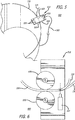
- FIG. 3 is a diagram 300 illustrating the invention for in-space propulsion of a spacecraft showing a top view of a removal device 310, which employs a cutting wheel 320, removing a portion of a structure 330 of a spacecraft, in accordance with the present invention.
- the removal device 310 employs a mechanical cutter, similar to a can opener design, that comprises a cutting wheel 320 and a serrated wheel 340.
- the removal device 310 is also shown to include a plurality of thrusters 350 and a cord 360.
- the removal device 310 which is a robotic device, will be used to "scavenge" material from the structure 330 to be used as solid propellant for a Hall thruster system located on the spacecraft.
- the structure 330 is an upper stage.
- the removal device 310 may "scavenge" various parts of the upper stage including, but not limited to, an upper stage housing and structural supports of the upper stage.
- the structure 330 may be a different structure from the spacecraft other than an upper stage.
- the structure 330 is manufactured from magnesium. Magnesium is structurally efficient, and is approximately thirty-four percent (34%) lighter in volume than aluminum. Magnesium has good fatigue resistance and vibration damping capacity. However, it should be noted that the structure 330 may be manufactured from materials other than magnesium including, but not limited to, bismuth, zinc, and indium.
- the removal device 310 After the spacecraft has been boosted into final orbit, the removal device 310, which is tethered to the structure 330 (or to another location on the spacecraft) via the cord 360, crawls (or moves) about the structure 330 while removing (by use of the cutting wheel 320) at least a portion of the structure 330 in the form of a ribbon 370.
- the combination of the cutting wheel 320 and the serrated wheel 340 assist in guiding the removal device 310 across the edge of the structure 330 during the removal of a portion of the structure 330.
- the thrusters 350 on the removal device 310 assist the removal device 310 in moving about the structure 330.
- the removal device 310 may comprise at least one wheel (and/or other similar types of conveyance devices, such as at least one roller ball) to assist itself in moving about the structure 330.
- the removal device 310 After the removal device 310 has removed the portion of the structure 330 in the form of a ribbon 370, the removal device 310 will feed the ribbon 370 into the Hall thruster system (not shown) located on the spacecraft (refer to FIG. 2 , which shows a solid ribbon 270 being fed into a Hall thruster system 210).
- the Hall thruster system will use the ribbon 370 as propellant to produce thrust for the spacecraft to achieve various on-orbit maneuvers.
- FIG. 4 is a diagram 400 showing a side view of the removal device 310 of FIG. 3 , in accordance with the present invention.
- the removal device 310 is shown to comprise a cutting wheel 320 and a serrated wheel 340.
- FIG. 5 is a diagram 500 depicting the disclosed system for in-space propulsion of a spacecraft showing a top view of a removal device 510, which employs a laser 520, removing a portion of a structure 330 of a spacecraft, in accordance with the present invention.
- the removal device 510 employs a laser cutter, which comprises a laser 520.
- the removal device 310 is also shown to include a pair of guiding wheels 530, a plurality of thrusters 550, and a cord 360.
- the removal device 510 which is a robotic device, will be used to "scavenge" material from the structure 330 to be used as solid propellant for a Hall thruster system located on the spacecraft.
- the removal device 510 which is tethered to the structure 330 (or to another location on the spacecraft) via the cord 360, crawls (or moves) about the structure 330 while removing (by use of the laser 520) at least a portion of the structure 330 in the form of a ribbon 370.
- the guiding wheels 530 assist in guiding the removal device 510 across the edge of the structure 330 during the removal of a portion of the structure 330.
- the thrusters 550 on the removal device 510 assist the removal device 510 in moving about the structure 330.
- the removal device 510 may comprise at least one wheel (and/or other similar types of conveyance devices, such as at least one roller ball) to assist itself in moving about the structure 330.
- the removal device 310 will feed the ribbon 370 into the Hall thruster system (not shown) located on the spacecraft (refer to FIG. 2 , which shows a solid ribbon 270 being fed into a Hall thruster system 210).
- the Hall thruster system will use the ribbon 370 as propellant to produce thrust for the spacecraft to achieve various on-orbit maneuvers.
- FIG. 6 is a diagram 600 showing a side view of the removal device 510 of FIG. 5 , in accordance with the present invention.
- the removal device 510 is shown to comprise a laser 520 and a pair of guiding wheels 530.
- the removal device 510 is shown to be removing (by use of the laser 520) at least a portion of the structure 330 in the form of a ribbon 370.
- FIG. 7 is a diagram 700 illustrating the disclosed system for in-space propulsion of a spacecraft showing a top view of a removal device 710, which employs a scissors mechanism 720, removing a portion of a structure 330 of a spacecraft, in accordance with the present invention.
- the removal device 710 employs a mechanical cutter, which comprises a scissors mechanism 720.
- the removal device 710 is also shown to include a pair of guiding wheels 730, a plurality of thrusters 750, and a cord 360.
- the removal device 710 which is a robotic device, will be used to "scavenge" material from the structure 330 to be used as solid propellant for a Hall thruster system located on the spacecraft.
- the removal device 710 which is tethered to the structure 330 (or to another location on the spacecraft) via the cord 360, crawls (or moves) about the structure 330 while removing (by use of the scissors mechanism 720) at least a portion of the structure 330 in the form of a ribbon 370.
- the guiding wheels 730 assist in guiding the removal device 710 across the edge of the structure 330 during the removal of a portion of the structure 330.
- the thrusters 750 on the removal device 710 assist the removal device 710 in moving about the structure 330.
- the removal device 710 may comprise at least one wheel (and/or other similar types of conveyance devices, such as at least one roller ball) to assist itself in moving about the structure 330.
- the removal device 710 After the removal device 710 has removed the portion of the structure 330 in the form of a ribbon 370, the removal device 710 will feed the ribbon 370 into the Hall thruster system (not shown) located on the spacecraft (refer to FIG. 2 , which shows a solid ribbon 270 being fed into a Hall thruster system 210).
- the Hall thruster system will use the ribbon 370 as propellant to produce thrust for the spacecraft to achieve various on-orbit maneuvers.
- FIG. 8 is a diagram 800 showing a side view of the removal device 710 of FIG. 7 , in accordance with the present invention.
- the removal device 710 is shown to comprise a scissors mechanism 720 and a pair of guiding wheels 730.
- the removal device 710 is shown to be removing (by use of the scissors mechanism 720) at least a portion of the structure 330 in the form of a ribbon 370.
- FIG. 9 is a flow chart depicting the disclosed method 900 for in-space propulsion of a spacecraft, in accordance with the present invention.
- a removal device removes a portion of a structure of a spacecraft 920. Then, the removal device feeds the portion into a Hall thruster system 930. The Hall thruster system then utilizes the portion to produce thrust 940. Then, the method 900 ends 950.
Landscapes
- Engineering & Computer Science (AREA)
- Chemical & Material Sciences (AREA)
- Combustion & Propulsion (AREA)
- Remote Sensing (AREA)
- Aviation & Aerospace Engineering (AREA)
- Physics & Mathematics (AREA)
- Plasma & Fusion (AREA)
- Mechanical Engineering (AREA)
- General Engineering & Computer Science (AREA)
- Optics & Photonics (AREA)
- Control Of Position, Course, Altitude, Or Attitude Of Moving Bodies (AREA)
- Laser Beam Processing (AREA)
Abstract
Description
- The present invention relates to a structural propellant. In particular, it relates to a structural propellant for ion rockets (SPIR).
- Spacecraft, such as satellites, require in-space propulsion systems for orbital station-keeping as well as for other on-orbit maneuvers. Hall thrusters are often employed on spacecraft to provide high specific impulse propulsion in-space. Hall thrusters require an inert propellant mass for expulsion. Currently, in conventional Hall thruster designs, Hall thruster propellant is stored in a propellant bottle. The disadvantage of these conventional designs is that the propellant and the propellant bottle represent significant mass on the spacecraft, and spacecraft launch costs are directly related to spacecraft mass. As such, these conventional designs for Hall thrusters, which require significant mass, contribute greatly to spacecraft launch costs. Therefore, there is a need for a solution for a lower mass Hall thruster design for spacecrafts.
- The present invention relates to a structural propellant for ion rockets (SPIR). A method for in-space propulsion of a spacecraft according to the present invention involves removing, by a removal device, a portion of a structure of the spacecraft. The method further involves feeding, by the removal device, the portion into a Hall thruster system. Further, the method involves utilizing, by the Hall thruster system, the portion as propellant to produce thrust.
- The removal device can comprise at least one mechanical cutter and/or at least one laser cutter. The at least one mechanical cutter may comprise at least one cutting wheel and/or at least one scissors mechanism.
- The structure can be an upper stage of the spacecraft. The upper stage may comprise at least one structural support and/or at least one upper stage housing. The structure can be manufactured from magnesium, bismuth, zinc, and/or indium.
- The portion of the structure can be removed by the removal device in the form of a ribbon. The removal device can be tethered to the spacecraft via at least one cord. The removal device can be a robotic device that moves about the spacecraft. The removal device can comprise at least one wheel and/or at least one thruster.
- A system for in-space propulsion of a spacecraft according to the present invention involves a removal device to remove a portion of a structure of the spacecraft, and to feed the portion into a Hall thruster system. The system further involves the Hall thruster system to utilize the portion as propellant to produce thrust.
- These and other features, aspects, and advantages of the present invention will become better understood with regard to the following description, appended claims, and accompanying drawings where:
-
FIG. 1 is a diagram depicting an exemplary upper stage of a spacecraft that may be employed by the disclosed system for in-space propulsion of a spacecraft, in accordance with the present invention. -
FIG. 2 is a diagram showing a Hall thruster system that may be employed by the disclosed system for in-space propulsion of a spacecraft, in accordance with the present invention. -
FIG. 3 is a diagram illustrating the disclosed system for in-space propulsion of a spacecraft showing a top view of a removal device, which employs a cutting wheel, removing a portion of a structure of a spacecraft, in accordance with the present invention. -
FIG. 4 is a diagram showing a side view of the removal device ofFIG. 3 , in accordance with the present invention. -
FIG. 5 is a diagram depicting the disclosed system for in-space propulsion of a spacecraft showing a top view of a removal device, which employs a laser, removing a portion of a structure of a spacecraft, in accordance with the present invention. -
FIG. 6 is a diagram showing a side view of the removal device ofFIG. 5 , in accordance with the present invention. -
FIG. 7 is a diagram illustrating the disclosed system for in-space propulsion of a spacecraft showing a top view of a removal device, which employs a scissors mechanism, removing a portion of a structure of a spacecraft, in accordance with the present invention. -
FIG. 8 is a diagram showing a side view of the removal device ofFIG. 7 , in accordance with the present invention. -
FIG. 9 is a flow chart depicting the disclosed method for in-space propulsion of a spacecraft, in accordance with the present invention. - The methods and apparatus disclosed herein provide an operative system for a structural propellant for ion rockets (SPIR). The system of the present disclosure provides a SPIR approach that utilizes excess spacecraft structure for fuel. In particular, the system provides a spacecraft comprising a specific structure that may be re-purposed for use as propellant mass for an on-board thruster. The specific structure to be re-purposed as fuel would be manufactured from magnesium, which would become the propellant mass for an ion thruster (e.g., a Hall thruster). For example, the upper stage structure of the spacecraft, which would be manufactured from magnesium, would be consumed as propellant by an on-board Hall thruster system.
- Typically, spacecraft launch loads greatly exceed in-space loads for most spacecraft. This results in excess structure on the spacecraft. This excess structure not only has no function on-orbit, but it further reduces the delta-v capability of the spacecraft's limited fuel, due to the increase in mass of the spacecraft. Using the unneeded structure for in-space propellant mass increases the available mass for the spacecraft payload.
- The system of the present invention provides propellant mass by consuming unneeded parts of the spacecraft structure. The system replaces existing spacecraft structure that is only required to meet launch loads, with a structure that may be eventually used for fuel. This configuration design both increases the available fuel supply and optimizes the total spacecraft mass usage.
- It should be noted that Hall thrusters have been built that use magnesium as the propellant. However, for these systems, the magnesium propellant is not "scavenged" from an unneeded structure, as is performed by the system of the present disclosure.
- In the following description, numerous details are set forth in order to provide a more thorough description of the system. It will be apparent, however, to one skilled in the art, that the disclosed system may be practiced without these specific details. In the other instances, well known features have not been described in detail so as not to unnecessarily obscure the system.
- The present invention may be described herein in terms of functional and/or logical components and various processing steps. It should be appreciated that such components may be realized by any number of hardware, software, and/or firmware components configured to perform the specified functions. For example, the present invention may employ various integrated circuit components (e.g., memory elements, digital signal processing elements, logic elements, look-up tables, or the like), which may carry out a variety of functions under the control of one or more processors, microprocessors, or other control devices.
-
FIG. 1 is a diagram 100 depicting an exemplaryupper stage 110 of a spacecraft that may be employed for in-space propulsion of a spacecraft, in accordance with the present invention. In this figure, theupper stage 110 shown is a Delta IV 2nd stage. - Also in this figure, the
upper stage 110 is shown to comprise anupper stage housing 120, which is cylindrical in shape. In addition, theupper stage 110 is shown to include a plurality ofstructural supports 130, which are in a lattice configuration. -
FIG. 2 is a diagram 200 showing aHall thruster system 210 that may be employed for in-space propulsion of a spacecraft, in accordance with the present invention. In this figure theHall thruster system 210 is shown to comprise aribbon conveyor 220, agas seal 230, avaporizer 240, anisolator 250, andHall thrusters 260. - During operation of the
Hall thruster system 210, asolid ribbon 270 of propellant is fed into theribbon conveyor 220. Magnesium ribbon can be the type ofsolid ribbon 270 that is being utilized by theHall thruster system 210. However, other types ofsolid ribbon 270 other than magnesium ribbon may be used including, but not limited to, bismuth, zinc, and indium ribbon. - The
ribbon conveyor 220 feeds thesolid ribbon 270 into agas seal 230. Then, avaporizer 240 heats thesolid ribbon 270 such that thesolid ribbon 250 is converted into a gas. Thegas seal 230 prevents the gas from leaking. - Then, an
isolator 250 is used to control the flow of the gas to theHall thrusters 260. TheHall thrusters 260 then use the gas as propellant to produce thrust. -
FIG. 3 is a diagram 300 illustrating the invention for in-space propulsion of a spacecraft showing a top view of aremoval device 310, which employs acutting wheel 320, removing a portion of astructure 330 of a spacecraft, in accordance with the present invention. In this figure, theremoval device 310 employs a mechanical cutter, similar to a can opener design, that comprises acutting wheel 320 and aserrated wheel 340. Theremoval device 310 is also shown to include a plurality ofthrusters 350 and acord 360. - During operation, after the spacecraft (not shown) has been boosted into final orbit, the
removal device 310, which is a robotic device, will be used to "scavenge" material from thestructure 330 to be used as solid propellant for a Hall thruster system located on the spacecraft. In this example, thestructure 330 is an upper stage. As such, theremoval device 310 may "scavenge" various parts of the upper stage including, but not limited to, an upper stage housing and structural supports of the upper stage. However, it should be noted that thestructure 330 may be a different structure from the spacecraft other than an upper stage. - Also, for this example, the
structure 330 is manufactured from magnesium. Magnesium is structurally efficient, and is approximately thirty-four percent (34%) lighter in volume than aluminum. Magnesium has good fatigue resistance and vibration damping capacity. However, it should be noted that thestructure 330 may be manufactured from materials other than magnesium including, but not limited to, bismuth, zinc, and indium. - After the spacecraft has been boosted into final orbit, the
removal device 310, which is tethered to the structure 330 (or to another location on the spacecraft) via thecord 360, crawls (or moves) about thestructure 330 while removing (by use of the cutting wheel 320) at least a portion of thestructure 330 in the form of aribbon 370. The combination of thecutting wheel 320 and theserrated wheel 340 assist in guiding theremoval device 310 across the edge of thestructure 330 during the removal of a portion of thestructure 330. Thethrusters 350 on theremoval device 310 assist theremoval device 310 in moving about thestructure 330. Theremoval device 310 may comprise at least one wheel (and/or other similar types of conveyance devices, such as at least one roller ball) to assist itself in moving about thestructure 330. - After the
removal device 310 has removed the portion of thestructure 330 in the form of aribbon 370, theremoval device 310 will feed theribbon 370 into the Hall thruster system (not shown) located on the spacecraft (refer toFIG. 2 , which shows asolid ribbon 270 being fed into a Hall thruster system 210). The Hall thruster system will use theribbon 370 as propellant to produce thrust for the spacecraft to achieve various on-orbit maneuvers. -
FIG. 4 is a diagram 400 showing a side view of theremoval device 310 ofFIG. 3 , in accordance with the present invention. In this figure, theremoval device 310 is shown to comprise acutting wheel 320 and aserrated wheel 340. -
FIG. 5 is a diagram 500 depicting the disclosed system for in-space propulsion of a spacecraft showing a top view of aremoval device 510, which employs alaser 520, removing a portion of astructure 330 of a spacecraft, in accordance with the present invention. In this figure, theremoval device 510 employs a laser cutter, which comprises alaser 520. Theremoval device 310 is also shown to include a pair of guidingwheels 530, a plurality ofthrusters 550, and acord 360. - During operation, after the spacecraft (not shown) has been boosted into final orbit, the
removal device 510, which is a robotic device, will be used to "scavenge" material from thestructure 330 to be used as solid propellant for a Hall thruster system located on the spacecraft. After the spacecraft has been boosted into final orbit, theremoval device 510, which is tethered to the structure 330 (or to another location on the spacecraft) via thecord 360, crawls (or moves) about thestructure 330 while removing (by use of the laser 520) at least a portion of thestructure 330 in the form of aribbon 370. The guidingwheels 530 assist in guiding theremoval device 510 across the edge of thestructure 330 during the removal of a portion of thestructure 330. Thethrusters 550 on theremoval device 510 assist theremoval device 510 in moving about thestructure 330. It should be noted that in other embodiments, theremoval device 510 may comprise at least one wheel (and/or other similar types of conveyance devices, such as at least one roller ball) to assist itself in moving about thestructure 330. - After the
removal device 510 has removed the portion of thestructure 330 in the form of aribbon 370, theremoval device 310 will feed theribbon 370 into the Hall thruster system (not shown) located on the spacecraft (refer toFIG. 2 , which shows asolid ribbon 270 being fed into a Hall thruster system 210). The Hall thruster system will use theribbon 370 as propellant to produce thrust for the spacecraft to achieve various on-orbit maneuvers. -
FIG. 6 is a diagram 600 showing a side view of theremoval device 510 ofFIG. 5 , in accordance with the present invention. In this figure, theremoval device 510 is shown to comprise alaser 520 and a pair of guidingwheels 530. Theremoval device 510 is shown to be removing (by use of the laser 520) at least a portion of thestructure 330 in the form of aribbon 370. -
FIG. 7 is a diagram 700 illustrating the disclosed system for in-space propulsion of a spacecraft showing a top view of aremoval device 710, which employs ascissors mechanism 720, removing a portion of astructure 330 of a spacecraft, in accordance with the present invention. In this figure, theremoval device 710 employs a mechanical cutter, which comprises ascissors mechanism 720. Theremoval device 710 is also shown to include a pair of guidingwheels 730, a plurality ofthrusters 750, and acord 360. - During operation, after the spacecraft (not shown) has been boosted into final orbit, the
removal device 710, which is a robotic device, will be used to "scavenge" material from thestructure 330 to be used as solid propellant for a Hall thruster system located on the spacecraft. After the spacecraft has been boosted into final orbit, theremoval device 710, which is tethered to the structure 330 (or to another location on the spacecraft) via thecord 360, crawls (or moves) about thestructure 330 while removing (by use of the scissors mechanism 720) at least a portion of thestructure 330 in the form of aribbon 370. The guidingwheels 730 assist in guiding theremoval device 710 across the edge of thestructure 330 during the removal of a portion of thestructure 330. Thethrusters 750 on theremoval device 710 assist theremoval device 710 in moving about thestructure 330. It should be noted that in other embodiments, theremoval device 710 may comprise at least one wheel (and/or other similar types of conveyance devices, such as at least one roller ball) to assist itself in moving about thestructure 330. - After the
removal device 710 has removed the portion of thestructure 330 in the form of aribbon 370, theremoval device 710 will feed theribbon 370 into the Hall thruster system (not shown) located on the spacecraft (refer toFIG. 2 , which shows asolid ribbon 270 being fed into a Hall thruster system 210). The Hall thruster system will use theribbon 370 as propellant to produce thrust for the spacecraft to achieve various on-orbit maneuvers. -
FIG. 8 is a diagram 800 showing a side view of theremoval device 710 ofFIG. 7 , in accordance with the present invention. In this figure, theremoval device 710 is shown to comprise ascissors mechanism 720 and a pair of guidingwheels 730. Theremoval device 710 is shown to be removing (by use of the scissors mechanism 720) at least a portion of thestructure 330 in the form of aribbon 370. -
FIG. 9 is a flow chart depicting the disclosedmethod 900 for in-space propulsion of a spacecraft, in accordance with the present invention. At the start 910 of themethod 900, a removal device removes a portion of a structure of aspacecraft 920. Then, the removal device feeds the portion into aHall thruster system 930. The Hall thruster system then utilizes the portion to producethrust 940. Then, themethod 900 ends 950. - Where methods described above indicate certain events occurring in certain order, those of ordinary skill in the art having the benefit of this disclosure would recognize that the ordering may be modified and that such modifications are in accordance with the variations of the present disclosure. Additionally, parts of methods may be performed concurrently in a parallel process when possible, as well as performed sequentially. In addition, more parts or less parts of the methods may be performed.
Claims (15)
- A method for in-space propulsion of a spacecraft, the method comprising:removing, by a removal device, a portion of a structure of the spacecraft;feeding, by the removal device, the portion into a Hall thruster system; andutilizing, by the Hall thruster system, the portion as propellant to produce thrust.
- The method of claim 1, wherein the removal device comprises at least one of at least one mechanical cutter and at least one laser cutter.
- The method of claim 2, wherein the at least one mechanical cutter comprises at least one of at least one cutting wheel and at least one scissors mechanism.
- The method of any of the claims 1-3, wherein the portion of the structure is removed by the removal device in the form of a ribbon.
- The method of any of the claims 1-4, wherein the removal device is tethered to the spacecraft via at least one cord.
- The method of any of the claims 1-5, wherein the removal device is a robotic device that moves about the spacecraft, and/or wherein the removal device comprises at least one of at least one wheel and at least one thruster.
- A system for in-space propulsion of a spacecraft, the system comprising:a removal device, and a Hall thruster system, whereby the removal device removes a portion of a structure of the spacecraft and feeds the portion into the Hall thruster system, which Hall thruster system utilizes the portion as propellant to produce thrust.
- The system of claim 7, wherein the removal device comprises at least one of at least one mechanical cutter and at least one laser cutter, preferably wherein the at least one mechanical cutter comprises at least one of at least one cutting wheel and at least one scissors mechanism.
- The system of any of the claims 7-8, wherein the structure is an upper stage of the spacecraft comprising at least one of at least one structural support and at least one upper stage housing.
- The system of any of the claims 7-9, wherein the structure is manufactured from at least one of magnesium, bismuth, zinc, and indium.
- The system of any of the claims 7-10, wherein the portion of the structure is removed by the removal device in the form of a ribbon.
- The system of any of the claims 7-11, wherein the removal device is tethered to the spacecraft via at least one cord.
- The system of any of the claims 7-12, wherein the removal device is a robotic device that moves about the spacecraft.
- The system of any of the claims 7-13, wherein the removal device comprises at least one of at least one wheel and at least one thruster.
- A spacecraft comprising a system according to any of the preceding claims 7-14.
Applications Claiming Priority (1)
| Application Number | Priority Date | Filing Date | Title |
|---|---|---|---|
| US15/004,818 US10428806B2 (en) | 2016-01-22 | 2016-01-22 | Structural Propellant for ion rockets (SPIR) |
Publications (2)
| Publication Number | Publication Date |
|---|---|
| EP3196131A1 true EP3196131A1 (en) | 2017-07-26 |
| EP3196131B1 EP3196131B1 (en) | 2020-05-20 |
Family
ID=57681259
Family Applications (1)
| Application Number | Title | Priority Date | Filing Date |
|---|---|---|---|
| EP16203663.6A Active EP3196131B1 (en) | 2016-01-22 | 2016-12-13 | Structural propellant for ion rockets (spir) |
Country Status (6)
| Country | Link |
|---|---|
| US (1) | US10428806B2 (en) |
| EP (1) | EP3196131B1 (en) |
| JP (1) | JP6853014B2 (en) |
| KR (1) | KR20170088306A (en) |
| CN (1) | CN107031869B (en) |
| TW (1) | TWI720112B (en) |
Families Citing this family (4)
| Publication number | Priority date | Publication date | Assignee | Title |
|---|---|---|---|---|
| US10724480B1 (en) * | 2017-03-17 | 2020-07-28 | Cu Aerospace, Llc | Monofilament vaporization propulsion systems |
| CA3103014A1 (en) * | 2018-06-13 | 2019-12-19 | Cu Aerospace, Llc | Fiber-fed advanced pulsed plasma thruster (fppt) |
| US10570892B2 (en) * | 2018-06-13 | 2020-02-25 | Cu Aerospace, Llc | Fiber-fed advanced pulsed plasma thruster (FPPT) |
| CN114291298B (en) * | 2021-12-21 | 2024-03-29 | 上海空间推进研究所 | Bismuth working medium electric propulsion supply system based on filament propellant |
Citations (4)
| Publication number | Priority date | Publication date | Assignee | Title |
|---|---|---|---|---|
| US6609363B1 (en) * | 1999-08-19 | 2003-08-26 | The United States Of America As Represented By The Secretary Of The Air Force | Iodine electric propulsion thrusters |
| US20050086926A1 (en) * | 2003-10-24 | 2005-04-28 | Michigan Technological University | Thruster apparatus and method |
| US20150021439A1 (en) * | 2012-02-01 | 2015-01-22 | Herakles | Space vehicle with electric propulsion and solid propellant chemical propulsion |
| US9334855B1 (en) * | 2005-12-01 | 2016-05-10 | Busek Company, Inc. | Hall thruster for use with a condensable propellant |
Family Cites Families (13)
| Publication number | Priority date | Publication date | Assignee | Title |
|---|---|---|---|---|
| US6373023B1 (en) * | 1999-03-02 | 2002-04-16 | General Dynamics (Ots) Aerospace, Inc. | ARC discharge initiation for a pulsed plasma thruster |
| US6445981B1 (en) * | 2000-03-02 | 2002-09-03 | Space Systems/Loral, Inc. | Controller and control method for satellite orbit-keeping maneuvers |
| DE10014034C2 (en) * | 2000-03-22 | 2002-01-24 | Thomson Tubes Electroniques Gm | Plasma accelerator arrangement |
| US20130067883A1 (en) * | 2004-09-22 | 2013-03-21 | Elwing Llc | Spacecraft thruster |
| EP2295797B1 (en) * | 2004-09-22 | 2013-01-23 | Elwing LLC | Spacecraft thruster |
| US20060207981A1 (en) * | 2005-03-18 | 2006-09-21 | Lincoln Global, Inc., A Delaware Corporation | Interchangeable wire drive for wire feeder and spool gun |
| CN100429496C (en) * | 2006-04-14 | 2008-10-29 | 中国科学院力学研究所 | Method and device for measuring jet thrust |
| EP2401204A4 (en) * | 2009-02-24 | 2017-07-05 | Blue Origin, LLC | Launch vehicles with fixed and deployable deceleration surfaces, and/or shaped fuel tanks, and associated systems and methods |
| FR2945842B1 (en) * | 2009-05-20 | 2011-07-01 | Snecma | PLASMA PROPELLER WITH HALL EFFECT. |
| KR20110085072A (en) * | 2010-01-19 | 2011-07-27 | 한국과학기술원 | Liquid single propellant thrusters with an array of catalyst bed structures to minimize catalyst bed breakage |
| FR3002594B1 (en) * | 2013-02-26 | 2016-09-30 | Snecma | SPIRAL PROPULSION MODULE WITH ELECTRIC PROPULSION AND CHEMICAL WITH SOLID PROPERGOL |
| CN104295462B (en) * | 2014-09-05 | 2017-02-15 | 兰州空间技术物理研究所 | Choke for adjusting flow rate of electric thrustor propellant and adjusting method |
| CN104648696B (en) * | 2014-12-11 | 2017-01-04 | 上海空间推进研究所 | Space metal propellant tank and manufacture method thereof |
-
2016
- 2016-01-22 US US15/004,818 patent/US10428806B2/en not_active Expired - Fee Related
- 2016-10-28 JP JP2016211479A patent/JP6853014B2/en not_active Expired - Fee Related
- 2016-12-13 EP EP16203663.6A patent/EP3196131B1/en active Active
-
2017
- 2017-01-18 CN CN201710040331.1A patent/CN107031869B/en not_active Expired - Fee Related
- 2017-01-20 KR KR1020170009649A patent/KR20170088306A/en not_active Withdrawn
- 2017-01-20 TW TW106102139A patent/TWI720112B/en not_active IP Right Cessation
Patent Citations (4)
| Publication number | Priority date | Publication date | Assignee | Title |
|---|---|---|---|---|
| US6609363B1 (en) * | 1999-08-19 | 2003-08-26 | The United States Of America As Represented By The Secretary Of The Air Force | Iodine electric propulsion thrusters |
| US20050086926A1 (en) * | 2003-10-24 | 2005-04-28 | Michigan Technological University | Thruster apparatus and method |
| US9334855B1 (en) * | 2005-12-01 | 2016-05-10 | Busek Company, Inc. | Hall thruster for use with a condensable propellant |
| US20150021439A1 (en) * | 2012-02-01 | 2015-01-22 | Herakles | Space vehicle with electric propulsion and solid propellant chemical propulsion |
Also Published As
| Publication number | Publication date |
|---|---|
| US10428806B2 (en) | 2019-10-01 |
| JP6853014B2 (en) | 2021-03-31 |
| JP2017129115A (en) | 2017-07-27 |
| TWI720112B (en) | 2021-03-01 |
| CN107031869B (en) | 2022-02-11 |
| CN107031869A (en) | 2017-08-11 |
| EP3196131B1 (en) | 2020-05-20 |
| KR20170088306A (en) | 2017-08-01 |
| TW201733859A (en) | 2017-10-01 |
| US20170211554A1 (en) | 2017-07-27 |
Similar Documents
| Publication | Publication Date | Title |
|---|---|---|
| EP3196131A1 (en) | Structural propellant for ion rockets (spir) | |
| US8457810B1 (en) | Compound steering law for efficient low thrust transfer orbit trajectory | |
| Oleson | Mission advantages of constant power, variable Isp electrostatic thrusters | |
| US9533774B1 (en) | Highly inclined elliptical orbit launch and orbit acquisition techniques | |
| Janovsky | End-of-life de-orbiting strategies for satellites | |
| US6817580B2 (en) | System and method for return and landing of launch vehicle booster stage | |
| CN101624096B (en) | Method for reducing the mass of fuel boarded during an interplanetary mission | |
| US12466582B2 (en) | Combined launch vehicle and satellite system | |
| Oleson | Advanced electric propulsion for RLV launched geosynchronous spacecraft | |
| US11794929B2 (en) | Method for ejecting a payload from a spacecraft driven by a continuous propulsion force | |
| Cheng | LM-4B sends Tianhui 2 satellite into orbit | |
| Wallace et al. | A review of the development of the T 6 ion thruster system | |
| Silvestrini et al. | Applicative gnc cases and examples | |
| Le et al. | Investigation of orbit rising to geo with combined chemical/electric propulsion systems | |
| Slyunyayev et al. | On The Possibility Of Removing Dangerous Technogenic waste | |
| MULLER | The Slinger-An in-orbit booster facility | |
| Woodcock | Designing an Enduring Mars Campaign | |
| Pergola et al. | The Satellite Sweeper Approach for the Solution of the Space Debris Problem | |
| EA052814B1 (en) | A combined launch vehicle and satellite system | |
| Parkin | The Performance of Black Arrow in the Launch of the Prospero Satellite | |
| Ash et al. | A methodology for selective removal of orbital debris | |
| Buongiorno et al. | The IRIS system-An Italian STS-upper stage | |
| Tarantini et al. | Development of a Nitrous Oxide-Based Monopropellant Propulsion System for Small Satellites | |
| Popov et al. | Analysis for possibility to use space platform with electric propulsion system in combination with the launch vehicle for air launch | |
| REY et al. | Space transportation: NASA has no firm need for increasingly costly orbital maneuvering vehicle |
Legal Events
| Date | Code | Title | Description |
|---|---|---|---|
| PUAI | Public reference made under article 153(3) epc to a published international application that has entered the european phase |
Free format text: ORIGINAL CODE: 0009012 |
|
| STAA | Information on the status of an ep patent application or granted ep patent |
Free format text: STATUS: REQUEST FOR EXAMINATION WAS MADE |
|
| 17P | Request for examination filed |
Effective date: 20161213 |
|
| AK | Designated contracting states |
Kind code of ref document: A1 Designated state(s): AL AT BE BG CH CY CZ DE DK EE ES FI FR GB GR HR HU IE IS IT LI LT LU LV MC MK MT NL NO PL PT RO RS SE SI SK SM TR |
|
| AX | Request for extension of the european patent |
Extension state: BA ME |
|
| STAA | Information on the status of an ep patent application or granted ep patent |
Free format text: STATUS: EXAMINATION IS IN PROGRESS |
|
| 17Q | First examination report despatched |
Effective date: 20180606 |
|
| REG | Reference to a national code |
Ref country code: DE Ref legal event code: R079 Ref document number: 602016036679 Country of ref document: DE Free format text: PREVIOUS MAIN CLASS: B64G0001400000 Ipc: B64G0001000000 |
|
| GRAJ | Information related to disapproval of communication of intention to grant by the applicant or resumption of examination proceedings by the epo deleted |
Free format text: ORIGINAL CODE: EPIDOSDIGR1 |
|
| STAA | Information on the status of an ep patent application or granted ep patent |
Free format text: STATUS: GRANT OF PATENT IS INTENDED |
|
| GRAP | Despatch of communication of intention to grant a patent |
Free format text: ORIGINAL CODE: EPIDOSNIGR1 |
|
| RIC1 | Information provided on ipc code assigned before grant |
Ipc: B64G 1/00 20060101AFI20190426BHEP Ipc: B64G 1/40 20060101ALI20190426BHEP Ipc: B64G 4/00 20060101ALI20190426BHEP Ipc: F03H 1/00 20060101ALI20190426BHEP |
|
| INTG | Intention to grant announced |
Effective date: 20190606 |
|
| GRAJ | Information related to disapproval of communication of intention to grant by the applicant or resumption of examination proceedings by the epo deleted |
Free format text: ORIGINAL CODE: EPIDOSDIGR1 |
|
| STAA | Information on the status of an ep patent application or granted ep patent |
Free format text: STATUS: EXAMINATION IS IN PROGRESS |
|
| GRAP | Despatch of communication of intention to grant a patent |
Free format text: ORIGINAL CODE: EPIDOSNIGR1 |
|
| STAA | Information on the status of an ep patent application or granted ep patent |
Free format text: STATUS: GRANT OF PATENT IS INTENDED |
|
| INTC | Intention to grant announced (deleted) | ||
| INTG | Intention to grant announced |
Effective date: 20191030 |
|
| GRAL | Information related to payment of fee for publishing/printing deleted |
Free format text: ORIGINAL CODE: EPIDOSDIGR3 |
|
| GRAS | Grant fee paid |
Free format text: ORIGINAL CODE: EPIDOSNIGR3 |
|
| GRAA | (expected) grant |
Free format text: ORIGINAL CODE: 0009210 |
|
| STAA | Information on the status of an ep patent application or granted ep patent |
Free format text: STATUS: THE PATENT HAS BEEN GRANTED |
|
| AK | Designated contracting states |
Kind code of ref document: B1 Designated state(s): AL AT BE BG CH CY CZ DE DK EE ES FI FR GB GR HR HU IE IS IT LI LT LU LV MC MK MT NL NO PL PT RO RS SE SI SK SM TR |
|
| REG | Reference to a national code |
Ref country code: GB Ref legal event code: FG4D |
|
| REG | Reference to a national code |
Ref country code: CH Ref legal event code: EP |
|
| REG | Reference to a national code |
Ref country code: DE Ref legal event code: R096 Ref document number: 602016036679 Country of ref document: DE |
|
| REG | Reference to a national code |
Ref country code: AT Ref legal event code: REF Ref document number: 1272464 Country of ref document: AT Kind code of ref document: T Effective date: 20200615 |
|
| REG | Reference to a national code |
Ref country code: LT Ref legal event code: MG4D |
|
| REG | Reference to a national code |
Ref country code: NL Ref legal event code: MP Effective date: 20200520 |
|
| PG25 | Lapsed in a contracting state [announced via postgrant information from national office to epo] |
Ref country code: GR Free format text: LAPSE BECAUSE OF FAILURE TO SUBMIT A TRANSLATION OF THE DESCRIPTION OR TO PAY THE FEE WITHIN THE PRESCRIBED TIME-LIMIT Effective date: 20200821 Ref country code: NO Free format text: LAPSE BECAUSE OF FAILURE TO SUBMIT A TRANSLATION OF THE DESCRIPTION OR TO PAY THE FEE WITHIN THE PRESCRIBED TIME-LIMIT Effective date: 20200820 Ref country code: LT Free format text: LAPSE BECAUSE OF FAILURE TO SUBMIT A TRANSLATION OF THE DESCRIPTION OR TO PAY THE FEE WITHIN THE PRESCRIBED TIME-LIMIT Effective date: 20200520 Ref country code: SE Free format text: LAPSE BECAUSE OF FAILURE TO SUBMIT A TRANSLATION OF THE DESCRIPTION OR TO PAY THE FEE WITHIN THE PRESCRIBED TIME-LIMIT Effective date: 20200520 Ref country code: FI Free format text: LAPSE BECAUSE OF FAILURE TO SUBMIT A TRANSLATION OF THE DESCRIPTION OR TO PAY THE FEE WITHIN THE PRESCRIBED TIME-LIMIT Effective date: 20200520 Ref country code: IS Free format text: LAPSE BECAUSE OF FAILURE TO SUBMIT A TRANSLATION OF THE DESCRIPTION OR TO PAY THE FEE WITHIN THE PRESCRIBED TIME-LIMIT Effective date: 20200920 Ref country code: PT Free format text: LAPSE BECAUSE OF FAILURE TO SUBMIT A TRANSLATION OF THE DESCRIPTION OR TO PAY THE FEE WITHIN THE PRESCRIBED TIME-LIMIT Effective date: 20200921 |
|
| PG25 | Lapsed in a contracting state [announced via postgrant information from national office to epo] |
Ref country code: HR Free format text: LAPSE BECAUSE OF FAILURE TO SUBMIT A TRANSLATION OF THE DESCRIPTION OR TO PAY THE FEE WITHIN THE PRESCRIBED TIME-LIMIT Effective date: 20200520 Ref country code: LV Free format text: LAPSE BECAUSE OF FAILURE TO SUBMIT A TRANSLATION OF THE DESCRIPTION OR TO PAY THE FEE WITHIN THE PRESCRIBED TIME-LIMIT Effective date: 20200520 Ref country code: RS Free format text: LAPSE BECAUSE OF FAILURE TO SUBMIT A TRANSLATION OF THE DESCRIPTION OR TO PAY THE FEE WITHIN THE PRESCRIBED TIME-LIMIT Effective date: 20200520 Ref country code: BG Free format text: LAPSE BECAUSE OF FAILURE TO SUBMIT A TRANSLATION OF THE DESCRIPTION OR TO PAY THE FEE WITHIN THE PRESCRIBED TIME-LIMIT Effective date: 20200820 |
|
| REG | Reference to a national code |
Ref country code: AT Ref legal event code: MK05 Ref document number: 1272464 Country of ref document: AT Kind code of ref document: T Effective date: 20200520 |
|
| PG25 | Lapsed in a contracting state [announced via postgrant information from national office to epo] |
Ref country code: NL Free format text: LAPSE BECAUSE OF FAILURE TO SUBMIT A TRANSLATION OF THE DESCRIPTION OR TO PAY THE FEE WITHIN THE PRESCRIBED TIME-LIMIT Effective date: 20200520 Ref country code: AL Free format text: LAPSE BECAUSE OF FAILURE TO SUBMIT A TRANSLATION OF THE DESCRIPTION OR TO PAY THE FEE WITHIN THE PRESCRIBED TIME-LIMIT Effective date: 20200520 |
|
| PG25 | Lapsed in a contracting state [announced via postgrant information from national office to epo] |
Ref country code: RO Free format text: LAPSE BECAUSE OF FAILURE TO SUBMIT A TRANSLATION OF THE DESCRIPTION OR TO PAY THE FEE WITHIN THE PRESCRIBED TIME-LIMIT Effective date: 20200520 Ref country code: IT Free format text: LAPSE BECAUSE OF FAILURE TO SUBMIT A TRANSLATION OF THE DESCRIPTION OR TO PAY THE FEE WITHIN THE PRESCRIBED TIME-LIMIT Effective date: 20200520 Ref country code: CZ Free format text: LAPSE BECAUSE OF FAILURE TO SUBMIT A TRANSLATION OF THE DESCRIPTION OR TO PAY THE FEE WITHIN THE PRESCRIBED TIME-LIMIT Effective date: 20200520 Ref country code: EE Free format text: LAPSE BECAUSE OF FAILURE TO SUBMIT A TRANSLATION OF THE DESCRIPTION OR TO PAY THE FEE WITHIN THE PRESCRIBED TIME-LIMIT Effective date: 20200520 Ref country code: SM Free format text: LAPSE BECAUSE OF FAILURE TO SUBMIT A TRANSLATION OF THE DESCRIPTION OR TO PAY THE FEE WITHIN THE PRESCRIBED TIME-LIMIT Effective date: 20200520 Ref country code: ES Free format text: LAPSE BECAUSE OF FAILURE TO SUBMIT A TRANSLATION OF THE DESCRIPTION OR TO PAY THE FEE WITHIN THE PRESCRIBED TIME-LIMIT Effective date: 20200520 Ref country code: DK Free format text: LAPSE BECAUSE OF FAILURE TO SUBMIT A TRANSLATION OF THE DESCRIPTION OR TO PAY THE FEE WITHIN THE PRESCRIBED TIME-LIMIT Effective date: 20200520 Ref country code: AT Free format text: LAPSE BECAUSE OF FAILURE TO SUBMIT A TRANSLATION OF THE DESCRIPTION OR TO PAY THE FEE WITHIN THE PRESCRIBED TIME-LIMIT Effective date: 20200520 |
|
| REG | Reference to a national code |
Ref country code: DE Ref legal event code: R097 Ref document number: 602016036679 Country of ref document: DE |
|
| PG25 | Lapsed in a contracting state [announced via postgrant information from national office to epo] |
Ref country code: SK Free format text: LAPSE BECAUSE OF FAILURE TO SUBMIT A TRANSLATION OF THE DESCRIPTION OR TO PAY THE FEE WITHIN THE PRESCRIBED TIME-LIMIT Effective date: 20200520 Ref country code: PL Free format text: LAPSE BECAUSE OF FAILURE TO SUBMIT A TRANSLATION OF THE DESCRIPTION OR TO PAY THE FEE WITHIN THE PRESCRIBED TIME-LIMIT Effective date: 20200520 |
|
| PLBE | No opposition filed within time limit |
Free format text: ORIGINAL CODE: 0009261 |
|
| STAA | Information on the status of an ep patent application or granted ep patent |
Free format text: STATUS: NO OPPOSITION FILED WITHIN TIME LIMIT |
|
| 26N | No opposition filed |
Effective date: 20210223 |
|
| PG25 | Lapsed in a contracting state [announced via postgrant information from national office to epo] |
Ref country code: SI Free format text: LAPSE BECAUSE OF FAILURE TO SUBMIT A TRANSLATION OF THE DESCRIPTION OR TO PAY THE FEE WITHIN THE PRESCRIBED TIME-LIMIT Effective date: 20200520 |
|
| REG | Reference to a national code |
Ref country code: CH Ref legal event code: PL |
|
| PG25 | Lapsed in a contracting state [announced via postgrant information from national office to epo] |
Ref country code: MC Free format text: LAPSE BECAUSE OF FAILURE TO SUBMIT A TRANSLATION OF THE DESCRIPTION OR TO PAY THE FEE WITHIN THE PRESCRIBED TIME-LIMIT Effective date: 20200520 |
|
| REG | Reference to a national code |
Ref country code: BE Ref legal event code: MM Effective date: 20201231 |
|
| PG25 | Lapsed in a contracting state [announced via postgrant information from national office to epo] |
Ref country code: IE Free format text: LAPSE BECAUSE OF NON-PAYMENT OF DUE FEES Effective date: 20201213 Ref country code: LU Free format text: LAPSE BECAUSE OF NON-PAYMENT OF DUE FEES Effective date: 20201213 |
|
| PG25 | Lapsed in a contracting state [announced via postgrant information from national office to epo] |
Ref country code: CH Free format text: LAPSE BECAUSE OF NON-PAYMENT OF DUE FEES Effective date: 20201231 Ref country code: LI Free format text: LAPSE BECAUSE OF NON-PAYMENT OF DUE FEES Effective date: 20201231 |
|
| PG25 | Lapsed in a contracting state [announced via postgrant information from national office to epo] |
Ref country code: TR Free format text: LAPSE BECAUSE OF FAILURE TO SUBMIT A TRANSLATION OF THE DESCRIPTION OR TO PAY THE FEE WITHIN THE PRESCRIBED TIME-LIMIT Effective date: 20200520 Ref country code: MT Free format text: LAPSE BECAUSE OF FAILURE TO SUBMIT A TRANSLATION OF THE DESCRIPTION OR TO PAY THE FEE WITHIN THE PRESCRIBED TIME-LIMIT Effective date: 20200520 Ref country code: CY Free format text: LAPSE BECAUSE OF FAILURE TO SUBMIT A TRANSLATION OF THE DESCRIPTION OR TO PAY THE FEE WITHIN THE PRESCRIBED TIME-LIMIT Effective date: 20200520 |
|
| PG25 | Lapsed in a contracting state [announced via postgrant information from national office to epo] |
Ref country code: MK Free format text: LAPSE BECAUSE OF FAILURE TO SUBMIT A TRANSLATION OF THE DESCRIPTION OR TO PAY THE FEE WITHIN THE PRESCRIBED TIME-LIMIT Effective date: 20200520 |
|
| PG25 | Lapsed in a contracting state [announced via postgrant information from national office to epo] |
Ref country code: BE Free format text: LAPSE BECAUSE OF NON-PAYMENT OF DUE FEES Effective date: 20201231 |
|
| PGFP | Annual fee paid to national office [announced via postgrant information from national office to epo] |
Ref country code: GB Payment date: 20221227 Year of fee payment: 7 Ref country code: FR Payment date: 20221227 Year of fee payment: 7 |
|
| PGFP | Annual fee paid to national office [announced via postgrant information from national office to epo] |
Ref country code: DE Payment date: 20221228 Year of fee payment: 7 |
|
| REG | Reference to a national code |
Ref country code: DE Ref legal event code: R119 Ref document number: 602016036679 Country of ref document: DE |
|
| GBPC | Gb: european patent ceased through non-payment of renewal fee |
Effective date: 20231213 |
|
| PG25 | Lapsed in a contracting state [announced via postgrant information from national office to epo] |
Ref country code: DE Free format text: LAPSE BECAUSE OF NON-PAYMENT OF DUE FEES Effective date: 20240702 |
|
| PG25 | Lapsed in a contracting state [announced via postgrant information from national office to epo] |
Ref country code: GB Free format text: LAPSE BECAUSE OF NON-PAYMENT OF DUE FEES Effective date: 20231213 |
|
| PG25 | Lapsed in a contracting state [announced via postgrant information from national office to epo] |
Ref country code: FR Free format text: LAPSE BECAUSE OF NON-PAYMENT OF DUE FEES Effective date: 20231231 |
|
| PG25 | Lapsed in a contracting state [announced via postgrant information from national office to epo] |
Ref country code: GB Free format text: LAPSE BECAUSE OF NON-PAYMENT OF DUE FEES Effective date: 20231213 Ref country code: FR Free format text: LAPSE BECAUSE OF NON-PAYMENT OF DUE FEES Effective date: 20231231 Ref country code: DE Free format text: LAPSE BECAUSE OF NON-PAYMENT OF DUE FEES Effective date: 20240702 |