EP3196092A1 - Railroad vibration control device - Google Patents
Railroad vibration control device Download PDFInfo
- Publication number
- EP3196092A1 EP3196092A1 EP15842665.0A EP15842665A EP3196092A1 EP 3196092 A1 EP3196092 A1 EP 3196092A1 EP 15842665 A EP15842665 A EP 15842665A EP 3196092 A1 EP3196092 A1 EP 3196092A1
- Authority
- EP
- European Patent Office
- Prior art keywords
- side chamber
- cylinder
- extension
- contraction
- cylinder device
- Prior art date
- Legal status (The legal status is an assumption and is not a legal conclusion. Google has not performed a legal analysis and makes no representation as to the accuracy of the status listed.)
- Withdrawn
Links
Images


Classifications
-
- B—PERFORMING OPERATIONS; TRANSPORTING
- B61—RAILWAYS
- B61F—RAIL VEHICLE SUSPENSIONS, e.g. UNDERFRAMES, BOGIES OR ARRANGEMENTS OF WHEEL AXLES; RAIL VEHICLES FOR USE ON TRACKS OF DIFFERENT WIDTH; PREVENTING DERAILING OF RAIL VEHICLES; WHEEL GUARDS, OBSTRUCTION REMOVERS OR THE LIKE FOR RAIL VEHICLES
- B61F5/00—Constructional details of bogies; Connections between bogies and vehicle underframes; Arrangements or devices for adjusting or allowing self-adjustment of wheel axles or bogies when rounding curves
- B61F5/02—Arrangements permitting limited transverse relative movements between vehicle underframe or bolster and bogie; Connections between underframes and bogies
- B61F5/04—Bolster supports or mountings
- B61F5/12—Bolster supports or mountings incorporating dampers
- B61F5/127—Bolster supports or mountings incorporating dampers with fluid as a damping medium
-
- B—PERFORMING OPERATIONS; TRANSPORTING
- B61—RAILWAYS
- B61F—RAIL VEHICLE SUSPENSIONS, e.g. UNDERFRAMES, BOGIES OR ARRANGEMENTS OF WHEEL AXLES; RAIL VEHICLES FOR USE ON TRACKS OF DIFFERENT WIDTH; PREVENTING DERAILING OF RAIL VEHICLES; WHEEL GUARDS, OBSTRUCTION REMOVERS OR THE LIKE FOR RAIL VEHICLES
- B61F5/00—Constructional details of bogies; Connections between bogies and vehicle underframes; Arrangements or devices for adjusting or allowing self-adjustment of wheel axles or bogies when rounding curves
- B61F5/02—Arrangements permitting limited transverse relative movements between vehicle underframe or bolster and bogie; Connections between underframes and bogies
- B61F5/22—Guiding of the vehicle underframes with respect to the bogies
- B61F5/24—Means for damping or minimising the canting, skewing, pitching, or plunging movements of the underframes
-
- B—PERFORMING OPERATIONS; TRANSPORTING
- B61—RAILWAYS
- B61F—RAIL VEHICLE SUSPENSIONS, e.g. UNDERFRAMES, BOGIES OR ARRANGEMENTS OF WHEEL AXLES; RAIL VEHICLES FOR USE ON TRACKS OF DIFFERENT WIDTH; PREVENTING DERAILING OF RAIL VEHICLES; WHEEL GUARDS, OBSTRUCTION REMOVERS OR THE LIKE FOR RAIL VEHICLES
- B61F5/00—Constructional details of bogies; Connections between bogies and vehicle underframes; Arrangements or devices for adjusting or allowing self-adjustment of wheel axles or bogies when rounding curves
- B61F5/02—Arrangements permitting limited transverse relative movements between vehicle underframe or bolster and bogie; Connections between underframes and bogies
- B61F5/04—Bolster supports or mountings
- B61F5/10—Bolster supports or mountings incorporating fluid springs
-
- B—PERFORMING OPERATIONS; TRANSPORTING
- B61—RAILWAYS
- B61F—RAIL VEHICLE SUSPENSIONS, e.g. UNDERFRAMES, BOGIES OR ARRANGEMENTS OF WHEEL AXLES; RAIL VEHICLES FOR USE ON TRACKS OF DIFFERENT WIDTH; PREVENTING DERAILING OF RAIL VEHICLES; WHEEL GUARDS, OBSTRUCTION REMOVERS OR THE LIKE FOR RAIL VEHICLES
- B61F5/00—Constructional details of bogies; Connections between bogies and vehicle underframes; Arrangements or devices for adjusting or allowing self-adjustment of wheel axles or bogies when rounding curves
- B61F5/02—Arrangements permitting limited transverse relative movements between vehicle underframe or bolster and bogie; Connections between underframes and bogies
- B61F5/14—Side bearings
- B61F5/144—Side bearings comprising fluid damping devices
-
- B—PERFORMING OPERATIONS; TRANSPORTING
- B61—RAILWAYS
- B61G—COUPLINGS; DRAUGHT AND BUFFING APPLIANCES
- B61G11/00—Buffers
- B61G11/12—Buffers with fluid springs or shock-absorbers; Combinations thereof
-
- F—MECHANICAL ENGINEERING; LIGHTING; HEATING; WEAPONS; BLASTING
- F15—FLUID-PRESSURE ACTUATORS; HYDRAULICS OR PNEUMATICS IN GENERAL
- F15B—SYSTEMS ACTING BY MEANS OF FLUIDS IN GENERAL; FLUID-PRESSURE ACTUATORS, e.g. SERVOMOTORS; DETAILS OF FLUID-PRESSURE SYSTEMS, NOT OTHERWISE PROVIDED FOR
- F15B11/00—Servomotor systems without provision for follow-up action; Circuits therefor
- F15B11/08—Servomotor systems without provision for follow-up action; Circuits therefor with only one servomotor
- F15B11/10—Servomotor systems without provision for follow-up action; Circuits therefor with only one servomotor in which the servomotor position is a function of the pressure also pressure regulators as operating means for such systems, the device itself may be a position indicating system
-
- F—MECHANICAL ENGINEERING; LIGHTING; HEATING; WEAPONS; BLASTING
- F16—ENGINEERING ELEMENTS AND UNITS; GENERAL MEASURES FOR PRODUCING AND MAINTAINING EFFECTIVE FUNCTIONING OF MACHINES OR INSTALLATIONS; THERMAL INSULATION IN GENERAL
- F16F—SPRINGS; SHOCK-ABSORBERS; MEANS FOR DAMPING VIBRATION
- F16F9/00—Springs, vibration-dampers, shock-absorbers, or similarly-constructed movement-dampers using a fluid or the equivalent as damping medium
- F16F9/10—Springs, vibration-dampers, shock-absorbers, or similarly-constructed movement-dampers using a fluid or the equivalent as damping medium using liquid only; using a fluid of which the nature is immaterial
- F16F9/14—Devices with one or more members, e.g. pistons, vanes, moving to and fro in chambers and using throttling effect
- F16F9/16—Devices with one or more members, e.g. pistons, vanes, moving to and fro in chambers and using throttling effect involving only straight-line movement of the effective parts
- F16F9/22—Devices with one or more members, e.g. pistons, vanes, moving to and fro in chambers and using throttling effect involving only straight-line movement of the effective parts with one or more cylinders each having a single working space closed by a piston or plunger
- F16F9/26—Devices with one or more members, e.g. pistons, vanes, moving to and fro in chambers and using throttling effect involving only straight-line movement of the effective parts with one or more cylinders each having a single working space closed by a piston or plunger with two cylinders in line and with the two pistons or plungers connected together
-
- F—MECHANICAL ENGINEERING; LIGHTING; HEATING; WEAPONS; BLASTING
- F16—ENGINEERING ELEMENTS AND UNITS; GENERAL MEASURES FOR PRODUCING AND MAINTAINING EFFECTIVE FUNCTIONING OF MACHINES OR INSTALLATIONS; THERMAL INSULATION IN GENERAL
- F16F—SPRINGS; SHOCK-ABSORBERS; MEANS FOR DAMPING VIBRATION
- F16F9/00—Springs, vibration-dampers, shock-absorbers, or similarly-constructed movement-dampers using a fluid or the equivalent as damping medium
- F16F9/32—Details
- F16F9/44—Means on or in the damper for manual or non-automatic adjustment; such means combined with temperature correction
- F16F9/46—Means on or in the damper for manual or non-automatic adjustment; such means combined with temperature correction allowing control from a distance, i.e. location of means for control input being remote from site of valves, e.g. on damper external wall
Definitions
- a conventionally known railroad vibration control device that includes an actuator, or a damper with a variable damping force, interposed between a vehicle body and a truck of a railroad vehicle during use so as to, for example, suppress vibration of the vehicle body in the leftward and rightward directions with respect to the traveling direction.
- a sensor detects vibration of a vehicle body.
- the damper with the variable damping force can exert the damping force in the direction of suppressing the vibration of the vehicle body, the damper increases the damping force.
- the damper minimizes the damping force.
- the damper thus implements skyhook control as a passive damper (see, for example, JPH 10-315965A).
- a railroad vibration control device including an actuator requires a pump for supplying hydraulic pressure to the actuator, and a motor that drives the pump. To control the motor, such a railroad vibration control device also requires an inverter for driving the motor, and a control box including a controller that generates a control command.
- the actuator needs to control vibration of a heavy vehicle body. Providing one actuator per truck to control vibration of the vehicle body may not produce sufficient forces. Therefore, it is often the case that two actuators are provided per truck. In this case, four actuators and four control boxes are required per vehicle. This harms the ease of mounting on the railroad vehicle, and increases the cost.
- the object of the present invention is to provide a railroad vibration control device that can effectively control vibration of a railroad vehicle without impairing the ease of mounting on the railroad vehicle.
- a railroad vibration control device S basically includes a first cylinder device A and a second cylinder device D.
- the first cylinder device A is disposed between a central pin P mounted on a vehicle body B of a railroad vehicle and a truck W.
- the second cylinder device D is disposed between the central pin P and the truck W so as to oppose the first cylinder device A via the central pin P. That is, the first cylinder device A and the second cylinder device D are interposed between the vehicle body B and the truck W while being arranged in parallel.
- a thrust force output by the first cylinder device A and a damping force output by the second cylinder device D suppress vibration of the vehicle body B in the leftward and rightward directions.
- the vehicle body B is elastically supported by air springs AS interposed between the vehicle body B and the truck W, and is allowed to move in the upward, downward, leftward, and rightward directions in FIG. 1 relative to the truck W.
- the first cylinder device A is configured as a single-rod actuator.
- the first cylinder device A includes a first cylinder body C1, a tank 7, a hydraulic pressure circuit LC that adjusts a thrust force generation direction and a thrust force of the first cylinder body C1, and a pump 12.
- the first cylinder body C1 includes a cylinder 2, a piston 3 that is slidably inserted into the cylinder 2, a rod 4 that is inserted into the cylinder 2 and joined to the piston 3, and an extension-side chamber 5 and a contraction-side chamber 6 that are separated from each other by the piston 3 inside the cylinder 2.
- the pump 12 supplies liquid to the extension-side chamber 5.
- extension driving of the first cylinder device A is performed by bringing the pump 12 into operation while communication via the first passage 8 is being established by the first on-off valve 9 and the second on-off valve 11 is closed.
- contraction driving of the first cylinder device A is performed by bringing the pump 12 into operation while communication via the second passage 10 is being established by the second on-off valve 11 and the first on-off valve 9 is closed.
- the cylinder 2 has a tubular shape. One end of the cylinder 2 (the right end in FIG. 2 ) is closed by a lid 13. An annular rod guide 14 is attached to the other end of the cylinder 2 (the left end in FIG. 2 ).
- the rod 4, which is movably inserted into the cylinder 2, is slidably inserted into the rod guide 14. One end of the rod 4 projects to the outside of the cylinder 2.
- the other end of the rod 4 is housed in the cylinder 2 and joined to the piston 3 that is similarly slidably inserted into the cylinder 2.
- a gap between an external circumference of the rod 4 and an internal circumference of the rod guide 14, and a gap between an external circumference of the rod guide 14 and the cylinder 2, are sealed by non-illustrated seal members.
- the interior of the cylinder 2 is maintained in an airtight state.
- the extension-side chamber 5 and the contraction-side chamber 6, which are separated from each other by the piston 3 inside the cylinder 2, are filled with working oil serving as the liquid.
- extension/contraction driving of the first cylinder device A During extension driving of the first cylinder device A, the extension-side chamber 5 and the contraction-side chamber 6 communicate with each other, and the pressure in the extension-side chamber 5 and the pressure in the contraction-side chamber 6 become equal; thus, the first cylinder device A generates a thrust force equivalent to a product of the equal pressure and the difference between the pressure receiving area of the piston 3 at the extension-side chamber 5 and the pressure receiving area of the piston 3 at the contraction-side chamber 6.
- the extension-side chamber 5 and the contraction-side chamber 6 do not communicate with each other, and the contraction-side chamber 6 communicates with the tank 7; thus, the first cylinder device A generates a trust force equivalent to a product of the pressure in the extension-side chamber 5 and the pressure receiving area of the piston 3 at the extension-side chamber 5.
- the value of the thrust force generated by the first cylinder device A is equivalent to a product of the pressure in the extension-side chamber 5 and 1/2 of the cross-sectional area of the piston 3 during both extension and contraction. It is hence sufficient to control the thrust force of the first cylinder device A by controlling the pressure in the extension-side chamber 5 during both extension driving and contraction driving.
- the pressure receiving area of the piston 3 at the extension-side chamber 5 is set to be 1/2 of the pressure receiving area of the piston 3 at the contraction-side chamber 6. Therefore, in order for the first cylinder device A to generate the same thrust force during both extension and contraction, it is sufficient to set the same pressure in the extension-side chamber 5 during extension driving and contraction driving. This achieves the advantage whereby control is simplified and the same flow rate is achieved with respect to the displacement amount, thereby attaining the same responsiveness during both extension and contraction.
- Non-illustrated attachment portions are mounted on one end of the rod 4 (the left end in FIG. 2 ) and the lid 13 that closes one end of the cylinder 2 (the right end in FIG. 2 ).
- the first cylinder device A is interposed between the vehicle body B and the truck W of the railroad vehicle via the attachment portions.
- the first cylinder device A also includes the flow adjustment passage 19 that allows the contraction-side chamber 6 to communicate with the extension-side chamber 5.
- a check valve 19a is provided on the flow adjustment passage 19.
- the flow adjustment passage 19 is set as a unidirectional passage that allows only the flow of the liquid from the contraction-side chamber 6 toward the extension-side chamber 5.
- the first cylinder device A exerts a thrust force whose value is equivalent to a product of the pressure in the extension-side chamber 5 and the contraction-side chamber 6, which is controlled by the variable relief valve 22 as stated earlier, and the difference between the pressure receiving area of the piston 3 at the extension-side chamber 5 and the pressure receiving area of the piston 3 at the contraction-side chamber 6.
- the first cylinder device A can function not only as the actuator, but also as a damper, regardless of the condition of driving performed by the motor 15.
- the first cylinder device A includes the suction passage 18 and the flow adjustment passage 19, when the first cylinder device A extends or contracts while the first on-off valve 9 and the second on-off valve 11 are in a closed state, the liquid is always discharged from inside the cylinder 2 to the tank 7 via the discharge passage 21.
- the extension-side chamber 5 and the contraction-side chamber 6 do not communicate with each other, whereas the contraction-side chamber 6 and the tank 7 communicate with each other.
- the extension-side chamber 5 is compressed and discharges the liquid to the tank 7 via the discharge passage 21.
- the liquid is supplied from the tank 7 to the expanding contraction-side chamber 6 without being subjected to resistance.
- the variable relief valve 22 imparts resistance to such a liquid flow, the first cylinder device A exerts a damping force in the extension direction.
- the first cylinder device A can be set as one of a one-way damper that exerts a damping force only during extension, a one-way damper that exerts a damping force only during contraction, and a damper that exerts a damping force during both extension and contraction.
- the hydraulic pressure circuit LC enables the first cylinder device A to function not only as the actuator, but also as the damper.
- the second cylinder device D is configured as a single-rod damper.
- the second cylinder device D includes a second cylinder body C2, a tank 37, and a damper circuit DC that adjusts a thrust force generation direction and a thrust force of the second cylinder body C2.
- the second cylinder body C2 includes a cylinder 32, a piston 33 that is slidably inserted into the cylinder 32, a rod 34 that is inserted into the cylinder 32 and joined to the piston 33, and an extension-side chamber 35 and a contraction-side chamber 36 that are separated from each other by the piston 33 inside the cylinder 32.
- the damper circuit DC includes a first on-off valve 39, a second on-off valve 41, a suction passage 48, a flow adjustment passage 49, a discharge passage 51, and a variable relief valve 52.
- the first on-off valve 39 is provided on a first passage 38 that allows the extension-side chamber 35 to communicate with the contraction-side chamber 36.
- the second on-off valve 41 is provided on a second passage 40 that allows the contraction-side chamber 36 to communicate with the tank 37.
- the suction passage 48 allows only the flow of the liquid from the tank 37 toward the contraction-side chamber 36.
- the flow adjustment passage 49 allows only the flow of the liquid from the contraction-side chamber 36 toward the extension-side chamber 35.
- the discharge passage 51 connects the extension-side chamber 35 and the tank 37.
- the variable relief valve 52 is provided on the discharge passage 51.
- the cylinder 32 has a tubular shape. One end of the cylinder 32 (the right end in FIG. 3 ) is closed by a lid 43. An annular rod guide 44 is attached to the other end of the cylinder 32 (the left end in FIG. 3 ). The rod 34, which is movably inserted into the cylinder 32, is slidably inserted into the rod guide 44. One end of the rod 34 projects to the outside of the cylinder 32. The other end of the rod 34 is housed in the cylinder 32 and joined to the piston 33 that is similarly slidably inserted into the cylinder 32.
- the extension-side chamber 35 and the contraction-side chamber 36 do not communicate with each other, and the contraction-side chamber 36 communicates with the tank 37; thus, the second cylinder device D generates a thrust force equivalent to a product of the pressure in the extension-side chamber 35 and the pressure receiving area of the piston 33 at the extension-side chamber 35.
- the value of the thrust force that is generated by the second cylinder device D is equivalent to a product of the pressure in the extension-side chamber 35 and 1/2 of the cross-sectional area of the piston 33 during both extension and contraction. It is hence sufficient to control the thrust force of the second cylinder device D by controlling the pressure in the extension-side chamber 35 during both extension driving and contraction driving.
- Non-illustrated attachment portions are mounted on one end of the rod 34 (the left end in FIG. 3 ) and the lid 43 that closes one end of the cylinder 32 (the right end in FIG. 3 ).
- the second cylinder device D is interposed between the vehicle body B and the truck W of the railroad vehicle via the attachment portions.
- the first on-off valve 39 is a solenoid on-off valve.
- the first on-off valve 39 includes a valve 39a, a spring 39d, and a solenoid 39e.
- the valve 39a has a communication position 39b to bring the extension-side chamber 35 and the contraction-side chamber 36 into communication with each other by opening the first passage 38, and a block position 39c to block communication between the extension-side chamber 35 and the contraction-side chamber 36.
- the spring 39d biases the valve 39a so that the valve 39a takes the block position 39c.
- the solenoid 39e switches the valve 39a to the communication position 39b in opposition to the spring 39d.
- the second on-off valve 41 is provided on the second passage 40.
- the second on-off valve 41 is a solenoid on-off valve.
- the second on-off valve 41 includes a valve 41a, a spring 41d, and a solenoid 41e.
- the valve 41a has a communication position 41b to bring the contraction-side chamber 36 and the tank 37 into communication with each other by opening the second passage 40, and a block position 41c to block communication between the contraction-side chamber 36 and the tank 37.
- the spring 41d biases the valve 41a so that the valve 41a takes the block position 41c.
- the solenoid 41e switches the valve 41a to the communication position 41b in opposition to the spring 41d.
- the extension-side chamber 35 and the tank 37 are connected to each other via the discharge passage 51.
- the variable relief valve 52 with a variable valve opening pressure is provided on the discharge passage 51.
- variable relief valve 52 when the pressure in the extension-side chamber 35 that is located upstream relative to the valve body 52a on the discharge passage 51 exceeds a relief pressure (valve opening pressure), a biasing force that is exerted by the spring 52b in the direction of blocking the discharge passage 51 is surpassed by a net force obtained from a thrust force generated by the proportional solenoid 52c and a thrust force exerted in the direction of opening the discharge passage 51 due to the pressure in the extension-side chamber 35. As a result, the variable relief valve 52 causes the valve body 52a to retreat, thereby opening the discharge passage 51.
- a relief pressure valve opening pressure
- variable relief valve 52 brings the extension-side chamber 35 into communication with the tank 37 by opening the discharge passage 51, whether the first on-off valve 39 and the second on-off valve 41 are in an opened state or a closed state. As a result, the pressure in the extension-side chamber 35 is released to the tank 37, and the entire system of the second cylinder device D is protected.
- the second cylinder device D also includes the suction passage 48 that allows the tank 37 to communicate with the contraction-side chamber 36.
- a check valve 48a is provided on the suction passage 48.
- the suction passage 48 is set as a unidirectional passage that allows only the flow of the liquid from the tank 37 toward the contraction-side chamber 36.
- suction passage 48 can be consolidated with the second passage 40 by using a check valve as the block position 41c of the second on-off valve 41.
- the flow adjustment passage 49 can be consolidated with the first passage 38 by using a check valve as the block position 39c of the first on-off valve 39.
Landscapes
- Engineering & Computer Science (AREA)
- Mechanical Engineering (AREA)
- General Engineering & Computer Science (AREA)
- Physics & Mathematics (AREA)
- Fluid Mechanics (AREA)
- Fluid-Pressure Circuits (AREA)
- Vehicle Body Suspensions (AREA)
- Vibration Prevention Devices (AREA)
- Fluid-Damping Devices (AREA)
Abstract
Description
- The present invention relates to a railroad vibration control device.
- There is a conventionally known railroad vibration control device that includes an actuator, or a damper with a variable damping force, interposed between a vehicle body and a truck of a railroad vehicle during use so as to, for example, suppress vibration of the vehicle body in the leftward and rightward directions with respect to the traveling direction.
- In a railroad vibration control device including an actuator, a sensor detects vibration of a vehicle body, and the vibration of the vehicle body is suppressed as the actuator exerts a thrust force in the direction of suppressing the vibration of the vehicle body. This can improve ride quality on the railroad vehicle (see, for example, JPH 06-239232A).
- Similarly, in a railroad vibration control device including a damper with a variable damping force, a sensor detects vibration of a vehicle body. When the damper with the variable damping force can exert the damping force in the direction of suppressing the vibration of the vehicle body, the damper increases the damping force. Conversely, when the damper can exert the damping force only in the direction of fostering the vibration of the vehicle body, the damper minimizes the damping force. The damper thus implements skyhook control as a passive damper (see, for example, JPH 10-315965A).
- A railroad vibration control device including an actuator requires a pump for supplying hydraulic pressure to the actuator, and a motor that drives the pump. To control the motor, such a railroad vibration control device also requires an inverter for driving the motor, and a control box including a controller that generates a control command. The actuator needs to control vibration of a heavy vehicle body. Providing one actuator per truck to control vibration of the vehicle body may not produce sufficient forces. Therefore, it is often the case that two actuators are provided per truck. In this case, four actuators and four control boxes are required per vehicle. This harms the ease of mounting on the railroad vehicle, and increases the cost.
- On the other hand, a railroad vibration control device including a damper with a variable damping force achieves a low vibration control effect compared with a railroad vibration control device that controls vibration using an actuator, because the damper cannot actively extend and contract.
- The object of the present invention is to provide a railroad vibration control device that can effectively control vibration of a railroad vehicle without impairing the ease of mounting on the railroad vehicle.
- According to one aspect of the present invention, a railroad vibration control device includes a first cylinder device and a second cylinder device. The first cylinder device includes a first cylinder body, a pump configured to supply hydraulic pressure to the first cylinder body, and a hydraulic pressure circuit configured to adjust a thrust force generation direction and a thrust force of the first cylinder body. The first cylinder body have a cylinder, a piston slidably inserted into the cylinder, and a rod inserted into the cylinder and joined to the piston. The second cylinder device includes a second cylinder body and a damper circuit configured to cause the second cylinder body to function as a damper. The second cylinder body having a cylinder, a piston slidably inserted into the cylinder, and a rod inserted into the cylinder and joined to the piston. The hydraulic pressure circuit and the damper circuit are the same circuit.
-
-
FIG. 1 shows a state in which a railroad vibration control device according to an embodiment is interposed between a vehicle body and a truck of a railroad vehicle. -
FIG. 2 is a schematic diagram of a first cylinder device of the railroad vibration control device according to the embodiment. -
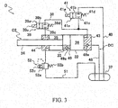
FIG. 3 is a schematic diagram of a second cylinder device of the railroad vibration control device according to the embodiment. - The present invention will be described below on the basis of an embodiment shown in the drawings. As shown in
FIG. 1 , a railroad vibration control device S according to one embodiment of the present invention basically includes a first cylinder device A and a second cylinder device D. The first cylinder device A is disposed between a central pin P mounted on a vehicle body B of a railroad vehicle and a truck W. The second cylinder device D is disposed between the central pin P and the truck W so as to oppose the first cylinder device A via the central pin P. That is, the first cylinder device A and the second cylinder device D are interposed between the vehicle body B and the truck W while being arranged in parallel. A thrust force output by the first cylinder device A and a damping force output by the second cylinder device D suppress vibration of the vehicle body B in the leftward and rightward directions. The vehicle body B is elastically supported by air springs AS interposed between the vehicle body B and the truck W, and is allowed to move in the upward, downward, leftward, and rightward directions inFIG. 1 relative to the truck W. - First, the first cylinder device A will be described. The first cylinder device A is configured as a single-rod actuator.
- Specifically, as shown in
FIG. 2 , the first cylinder device A includes a first cylinder body C1, atank 7, a hydraulic pressure circuit LC that adjusts a thrust force generation direction and a thrust force of the first cylinder body C1, and apump 12. The first cylinder body C1 includes acylinder 2, apiston 3 that is slidably inserted into thecylinder 2, a rod 4 that is inserted into thecylinder 2 and joined to thepiston 3, and an extension-side chamber 5 and a contraction-side chamber 6 that are separated from each other by thepiston 3 inside thecylinder 2. Thepump 12 supplies liquid to the extension-side chamber 5. - The extension-
side chamber 5 and the contraction-side chamber 6 are filled with the liquid, for example, working oil. Thetank 7 is filled with the liquid and gas. Note that the interior of thetank 7 need not particularly be placed in a pressurized state by compressed gas filling. - The hydraulic pressure circuit LC includes a first on-off
valve 9, a second on-offvalve 11, asuction passage 18, aflow adjustment passage 19, adischarge passage 21, and avariable relief valve 22. The first on-offvalve 9 is provided on a first passage 8 that allows the extension-side chamber 5 to communicate with the contraction-side chamber 6. The second on-offvalve 11 is provided on asecond passage 10 that allows the contraction-side chamber 6 to communicate with thetank 7. Thesuction passage 18 allows only the flow of the liquid from thetank 7 toward the contraction-side chamber 6. Theflow adjustment passage 19 allows only the flow of the liquid from the contraction-side chamber 6 toward the extension-side chamber 5. Thedischarge passage 21 connects the extension-side chamber 5 and thetank 7. Thevariable relief valve 22 is provided on thedischarge passage 21. - Basically, extension driving of the first cylinder device A is performed by bringing the
pump 12 into operation while communication via the first passage 8 is being established by the first on-offvalve 9 and the second on-offvalve 11 is closed. On the other hand, contraction driving of the first cylinder device A is performed by bringing thepump 12 into operation while communication via thesecond passage 10 is being established by the second on-offvalve 11 and the first on-offvalve 9 is closed. - The components of the first cylinder device A will now be described in detail. The
cylinder 2 has a tubular shape. One end of the cylinder 2 (the right end inFIG. 2 ) is closed by alid 13. Anannular rod guide 14 is attached to the other end of the cylinder 2 (the left end inFIG. 2 ). The rod 4, which is movably inserted into thecylinder 2, is slidably inserted into therod guide 14. One end of the rod 4 projects to the outside of thecylinder 2. The other end of the rod 4 is housed in thecylinder 2 and joined to thepiston 3 that is similarly slidably inserted into thecylinder 2. - A gap between an external circumference of the rod 4 and an internal circumference of the
rod guide 14, and a gap between an external circumference of therod guide 14 and thecylinder 2, are sealed by non-illustrated seal members. Thus, the interior of thecylinder 2 is maintained in an airtight state. As stated earlier, the extension-side chamber 5 and the contraction-side chamber 6, which are separated from each other by thepiston 3 inside thecylinder 2, are filled with working oil serving as the liquid. - In the first cylinder device A, a cross-sectional area of the rod 4 is 1/2 of a cross-sectional area of the
piston 3, and a pressure receiving area of thepiston 3 at the extension-side chamber 5 is 1/2 of a pressure receiving area of thepiston 3 at the contraction-side chamber 6. By setting the same pressure in the extension-side chamber 5 during extension driving and contraction driving, the same thrust force is generated during both extension and contraction, and the same flow rate is achieved with respect to a displacement amount of the first cylinder device A during both extension and contraction. - Below is a more detailed description of extension/contraction driving of the first cylinder device A. During extension driving of the first cylinder device A, the extension-
side chamber 5 and the contraction-side chamber 6 communicate with each other, and the pressure in the extension-side chamber 5 and the pressure in the contraction-side chamber 6 become equal; thus, the first cylinder device A generates a thrust force equivalent to a product of the equal pressure and the difference between the pressure receiving area of thepiston 3 at the extension-side chamber 5 and the pressure receiving area of thepiston 3 at the contraction-side chamber 6. In contrast, during contraction driving of the first cylinder device A, the extension-side chamber 5 and the contraction-side chamber 6 do not communicate with each other, and the contraction-side chamber 6 communicates with thetank 7; thus, the first cylinder device A generates a trust force equivalent to a product of the pressure in the extension-side chamber 5 and the pressure receiving area of thepiston 3 at the extension-side chamber 5. - Thus, the value of the thrust force generated by the first cylinder device A is equivalent to a product of the pressure in the extension-
side chamber 5 and 1/2 of the cross-sectional area of thepiston 3 during both extension and contraction. It is hence sufficient to control the thrust force of the first cylinder device A by controlling the pressure in the extension-side chamber 5 during both extension driving and contraction driving. - In the first cylinder device A, the pressure receiving area of the
piston 3 at the extension-side chamber 5 is set to be 1/2 of the pressure receiving area of thepiston 3 at the contraction-side chamber 6. Therefore, in order for the first cylinder device A to generate the same thrust force during both extension and contraction, it is sufficient to set the same pressure in the extension-side chamber 5 during extension driving and contraction driving. This achieves the advantage whereby control is simplified and the same flow rate is achieved with respect to the displacement amount, thereby attaining the same responsiveness during both extension and contraction. - Note that even when the pressure receiving area of the
piston 3 at the extension-side chamber 5 is not set to be 1/2 of the pressure receiving area of thepiston 3 at the contraction-side chamber 6, it is still possible to control the thrust force of the first cylinder device A during both extension and contraction with use of the pressure in the extension-side chamber 5. - Non-illustrated attachment portions are mounted on one end of the rod 4 (the left end in
FIG. 2 ) and thelid 13 that closes one end of the cylinder 2 (the right end inFIG. 2 ). The first cylinder device A is interposed between the vehicle body B and the truck W of the railroad vehicle via the attachment portions. - The extension-
side chamber 5 and the contraction-side chamber 6 communicate with each other through the first passage 8. The first on-offvalve 9 is provided on the first passage 8. Although the first passage 8 that allows the extension-side chamber 5 to communicate with the contraction-side chamber 6 is located outside thecylinder 2, it may be located in thepiston 3. - In the present embodiment, the first on-off
valve 9 is a solenoid on-off valve. Specifically, the first on-offvalve 9 includes avalve 9a, aspring 9d, and asolenoid 9e. Thevalve 9a has acommunication position 9b to bring the extension-side chamber 5 and the contraction-side chamber 6 into communication with each other by opening the first passage 8, and ablock position 9c to block communication between the extension-side chamber 5 and the contraction-side chamber 6. Thespring 9d biases thevalve 9a so that thevalve 9a takes theblock position 9c. When current is flowing through thesolenoid 9e, thesolenoid 9e switches thevalve 9a to thecommunication position 9b in opposition to thespring 9d. - The contraction-
side chamber 6 and thetank 7 communicate with each other throughsecond passage 10. The second on-offvalve 11 is provided on thesecond passage 10. In the present embodiment, the second on-offvalve 11 is a solenoid on-off valve. Specifically, the second on-offvalve 11 includes avalve 11a, aspring 11d, and a solenoid 11e. Thevalve 11a has a communication position 11b to bring the contraction-side chamber 6 and thetank 7 into communication with each other by opening thesecond passage 10, and ablock position 11c to block communication between the contraction-side chamber 6 and thetank 7. Thespring 11d biases thevalve 11a so that thevalve 11a takes theblock position 11c. When current is flowing through the solenoid 11e, the solenoid 11e switches thevalve 11a to the communication position 11b in opposition to thespring 11d. - The
pump 12 is driven by amotor 15. Thepump 12 discharges the liquid only in one direction. A discharge port of thepump 12 communicates with the extension-side chamber 5 via asupply passage 16. A suction port of thepump 12 communicates with thetank 7. When driven by themotor 15, thepump 12 suctions the liquid from thetank 7 and supplies the liquid to the extension-side chamber 5. - As stated earlier, the
pump 12 simply discharges the liquid only in one direction, and does not switch its rotation direction. Therefore, thepump 12 does not face the problem of a change in the discharge amount at the time of rotation switching. For this reason, an inexpensive gear pump and the like can be used as thepump 12. Furthermore, as thepump 12 always rotates in the same direction, themotor 15, which serves as a driving source that drives thepump 12, is not required to be highly responsive to rotation switching. For this reason, an inexpensive motor can be used as themotor 15 as well. - A
check valve 17 that prevents the reverse flow of the liquid from the extension-side chamber 5 to thepump 12 is provided on thesupply passage 16. As the reverse flow of the liquid to thepump 12 is thus prevented, the first cylinder device A can exert a significant force in the direction opposite to the operation direction without getting restricted by the maximum torque of themotor 15. - The extension-
side chamber 5 and thetank 7 are connected to each other via thedischarge passage 21. Thevariable relief valve 22 with a variable valve opening pressure is provided on thedischarge passage 21. - The
variable relief valve 22 includes avalve body 22a provided on thedischarge passage 21, aspring 22b that biases thevalve body 22a to block thedischarge passage 21, and aproportional solenoid 22c that generates a thrust force opposing thespring 22b when current is flowing therethrough. The valve opening pressure is adjusted by adjusting the amount of current flowing through theproportional solenoid 22c. - In the
variable relief valve 22, when the pressure in the extension-side chamber 5 that is located upstream relative to thevalve body 22a on thedischarge passage 21 exceeds a relief pressure (valve opening pressure), a biasing force that is exerted by thespring 22b in the direction of blocking thedischarge passage 21 is surpassed by a net force obtained from a thrust force generated by theproportional solenoid 22c and a thrust force exerted in the direction of opening thedischarge passage 21 due to the pressure in the extension-side chamber 5. As a result, thevariable relief valve 22 causes thevalve body 22a to retreat, thereby opening thedischarge passage 21. - In the
variable relief valve 22, the thrust force that is generated by theproportional solenoid 22c increases as the amount of current supplied to theproportional solenoid 22c increases. Supplying the maximum amount of current to theproportional solenoid 22c minimizes the valve opening pressure. Conversely, supplying no current to theproportional solenoid 22c at all maximizes the valve opening pressure. - When the pressure in the extension-
side chamber 5 exceeds the valve opening pressure due to excess input to the first cylinder device A in the extension or contraction direction, thevariable relief valve 22 brings the extension-side chamber 5 into communication with thetank 7 by opening thedischarge passage 21, whether the first on-offvalve 9 and the second on-offvalve 11 are in an opened state or a closed state. As a result, the pressure in the extension-side chamber 5 is released to thetank 7, and the entire system of the first cylinder device A is protected. - The first cylinder device A also includes the
suction passage 18 that allows thetank 7 to communicate with the contraction-side chamber 6. Acheck valve 18a is provided on thesuction passage 18. Thesuction passage 18 is set as a unidirectional passage that allows only the flow of the liquid from thetank 7 toward the contraction-side chamber 6. - The first cylinder device A also includes the
flow adjustment passage 19 that allows the contraction-side chamber 6 to communicate with the extension-side chamber 5. Acheck valve 19a is provided on theflow adjustment passage 19. Theflow adjustment passage 19 is set as a unidirectional passage that allows only the flow of the liquid from the contraction-side chamber 6 toward the extension-side chamber 5. - Note that the
suction passage 18 can be consolidated with thesecond passage 10 by using a check valve as theblock position 11c of the second on-offvalve 11. Theflow adjustment passage 19 can be consolidated with the first passage 8 by using a check valve as theblock position 9c of the first on-offvalve 9. - In order for the first cylinder device A to exert a desired thrust force in the extension direction, the first on-off
valve 9 is switched to thecommunication position 9b, and the second on-offvalve 11 is switched to theblock position 11c. Rotating themotor 15 at a predetermined rotation frequency causes thepump 12 to supply the liquid into thecylinder 2. The extension-side chamber 5 and the contraction-side chamber 6 are brought into communication with each other, and thepump 12 supplies the liquid to both of them. Therefore, thepiston 3 is pressed in the extension direction (leftward inFIG. 2 ), and the first cylinder device A exerts a thrust force in the extension direction. - At this time, when the pressure in the extension-
side chamber 5 and the contraction-side chamber 6 exceeds the valve opening pressure of thevariable relief valve 22, thevariable relief valve 22 is opened, and the liquid is released to thetank 7 via thedischarge passage 21. That is, the pressure in the extension-side chamber 5 and the contraction-side chamber 6 is controlled by the valve opening pressure of thevariable relief valve 22, which is dependent on the amount of current supplied to thevariable relief valve 22. Therefore, in the extension direction, the first cylinder device A exerts a thrust force whose value is equivalent to a product of the pressure in the extension-side chamber 5 and the contraction-side chamber 6, which is controlled by thevariable relief valve 22 as stated earlier, and the difference between the pressure receiving area of thepiston 3 at the extension-side chamber 5 and the pressure receiving area of thepiston 3 at the contraction-side chamber 6. - On the other hand, in order for the first cylinder device A to exert a desired thrust force in the contraction direction, the first on-off
valve 9 is switched to theblock position 9c, and the second on-offvalve 11 is switched to the communication position 11b. Rotating themotor 15 at a predetermined rotation frequency causes thepump 12 to supply the liquid into the extension-side chamber 5. The contraction-side chamber 6 and thetank 7 are brought into communication with each other, and thepump 12 supplies the liquid to the extension-side chamber 5. Therefore, thepiston 3 is pressed in the contraction direction (rightward inFIG. 2 ), and the first cylinder device A exerts a thrust force in the contraction direction. - Similarly to the case in which a thrust force is exerted in the extension direction, the pressure in the extension-
side chamber 5 is controlled by adjusting the amount of current supplied to thevariable relief valve 22. Therefore, in the contraction direction, the first cylinder device A exerts a thrust force whose value is obtained by subtracting a product of the pressure receiving area of thepiston 3 at the contraction-side chamber 6 and the tank pressure from a product of the pressure receiving area of thepiston 3 at the extension-side chamber 5 and the pressure in the extension-side chamber 5 controlled by thevariable relief valve 22. - As described above, rotating the
motor 15 at a predetermined rotation frequency and a constant speed causes no change in the rotation frequency of thepump 12. As a result, the occurrence of noise associated with fluctuations in the rotation frequency of thepump 12 can be prevented, and the first cylinder device A can demonstrate favorable control-related responsiveness. The first cylinder device A may be adjusted by the combination of pressure adjustment by thevariable relief valve 22 and a change in the rotation frequency of themotor 15. - The first cylinder device A can function not only as the actuator, but also as a damper, regardless of the condition of driving performed by the
motor 15. As the first cylinder device A includes thesuction passage 18 and theflow adjustment passage 19, when the first cylinder device A extends or contracts while the first on-offvalve 9 and the second on-offvalve 11 are in a closed state, the liquid is always discharged from inside thecylinder 2 to thetank 7 via thedischarge passage 21. - Specifically, when the first cylinder device A extends while the first on-off
valve 9 and the second on-offvalve 11 are in a closed state, the extension-side chamber 5 is compressed, and the liquid is discharged to thetank 7 via thedischarge passage 21. At this time, the liquid is supplied from thetank 7 to the expanding contraction-side chamber 6 via thesuction passage 18. - Conversely, when the first cylinder device A contracts while the first on-off
valve 9 and the second on-offvalve 11 are in a closed state, the contraction-side chamber 6 is compressed, and the liquid moves to the extension-side chamber 5 via theflow adjustment passage 19. At this time, excess liquid resulting from the insertion of the rod 4 into thecylinder 2 is discharged from inside thecylinder 2 to thetank 7 via thedischarge passage 21. - As described above, when the first cylinder device A extends or contracts, the liquid is always discharged from inside the
cylinder 2 to thetank 7 via thedischarge passage 21. By controlling the pressure in the extension-side chamber 5 with resistance imparted to such a liquid flow with use of thevariable relief valve 22, a desired damping force is exerted by the first cylinder device A. Furthermore, in the first cylinder device A, as the pressure receiving area of thepiston 3 at the extension-side chamber 5 is set to be 1/2 of the pressure receiving area of thepiston 3 at the contraction-side chamber 6, the first cylinder device A exerts the same damping force during both extension and contraction unless the valve opening pressure of thevariable relief valve 22 changes. - When the first cylinder device A contracts while communication between the extension-
side chamber 5 and the contraction-side chamber 6 is being established by opening the first on-offvalve 9 and closing the second on-offvalve 11, the extension-side chamber 5 and the contraction-side chamber 6 are compressed due to the insertion of the rod 4 into thecylinder 2. As a result, liquid corresponding to the volume by which the rod 4 is inserted into thecylinder 2 is discharged to thetank 7 via thedischarge passage 21. As thevariable relief valve 22 imparts resistance to such a liquid flow, the first cylinder device A exerts a damping force in the contraction direction. - Conversely, when the first cylinder device A extends while communication between the extension-
side chamber 5 and the contraction-side chamber 6 is being established by opening the first on-offvalve 9 and closing the second on-offvalve 11, the liquid moves from the extension-side chamber 5 to the contraction-side chamber 6 without being subjected to resistance. At this time, insufficiency of liquid caused by withdrawal of the rod 4 from inside thecylinder 2 is compensated for by supplying the liquid from thetank 7 via thesuction passage 18. Therefore, during such extension of the first cylinder device A, the liquid does not flow through thevariable relief valve 22, and thus the first cylinder device A does not exert a damping force in the extension direction. - While the first on-off
valve 9 is in a closed state and the second on-offvalve 11 is in an opened state, the extension-side chamber 5 and the contraction-side chamber 6 do not communicate with each other, whereas the contraction-side chamber 6 and thetank 7 communicate with each other. When the first cylinder device A extends in this state, the extension-side chamber 5 is compressed and discharges the liquid to thetank 7 via thedischarge passage 21. The liquid is supplied from thetank 7 to the expanding contraction-side chamber 6 without being subjected to resistance. As thevariable relief valve 22 imparts resistance to such a liquid flow, the first cylinder device A exerts a damping force in the extension direction. - Conversely, when the first cylinder device A contracts while the first on-off
valve 9 is in a closed state and the second on-offvalve 11 is in an opened state, the liquid moves from the compressed contraction-side chamber 6 to the expanding extension-side chamber 5 via theflow adjustment passage 19 without being subjected to resistance. As the contraction-side chamber 6 and thetank 7 communicate with each other, excess liquid resulting from the insertion of the rod 4 into thecylinder 2 is discharged from inside thecylinder 2 to thetank 7 without being subjected to resistance. Therefore, during such contraction of the first cylinder device A, the liquid does not flow through thevariable relief valve 22, and thus the first cylinder device A does not exert a damping force in the contraction direction. - As described above, with the first on-off
valve 9 and the second on-offvalve 11 that switch between an opened state and a closed state, the first cylinder device A can be set as one of a one-way damper that exerts a damping force only during extension, a one-way damper that exerts a damping force only during contraction, and a damper that exerts a damping force during both extension and contraction. Thus, the hydraulic pressure circuit LC enables the first cylinder device A to function not only as the actuator, but also as the damper. - Next, the second cylinder device D will be described. The second cylinder device D is configured as a single-rod damper.
- Specifically, as shown in
FIG. 3 , the second cylinder device D includes a second cylinder body C2, atank 37, and a damper circuit DC that adjusts a thrust force generation direction and a thrust force of the second cylinder body C2. The second cylinder body C2 includes acylinder 32, apiston 33 that is slidably inserted into thecylinder 32, arod 34 that is inserted into thecylinder 32 and joined to thepiston 33, and an extension-side chamber 35 and a contraction-side chamber 36 that are separated from each other by thepiston 33 inside thecylinder 32. - The extension-
side chamber 35 and the contraction-side chamber 36 are filled with liquid, such as working oil. Thetank 37 is filled with the liquid and gas. Note that the interior of thetank 37 need not particularly be placed in a pressurized state by compressed gas filling. - The damper circuit DC includes a first on-off
valve 39, a second on-offvalve 41, asuction passage 48, aflow adjustment passage 49, adischarge passage 51, and avariable relief valve 52. The first on-offvalve 39 is provided on afirst passage 38 that allows the extension-side chamber 35 to communicate with the contraction-side chamber 36. The second on-offvalve 41 is provided on asecond passage 40 that allows the contraction-side chamber 36 to communicate with thetank 37. Thesuction passage 48 allows only the flow of the liquid from thetank 37 toward the contraction-side chamber 36. Theflow adjustment passage 49 allows only the flow of the liquid from the contraction-side chamber 36 toward the extension-side chamber 35. Thedischarge passage 51 connects the extension-side chamber 35 and thetank 37. Thevariable relief valve 52 is provided on thedischarge passage 51. - The components of the second cylinder device D will now be described in detail. The
cylinder 32 has a tubular shape. One end of the cylinder 32 (the right end inFIG. 3 ) is closed by alid 43. Anannular rod guide 44 is attached to the other end of the cylinder 32 (the left end inFIG. 3 ). Therod 34, which is movably inserted into thecylinder 32, is slidably inserted into therod guide 44. One end of therod 34 projects to the outside of thecylinder 32. The other end of therod 34 is housed in thecylinder 32 and joined to thepiston 33 that is similarly slidably inserted into thecylinder 32. - A gap between an external circumference of the
rod 34 and an internal circumference of therod guide 44, and a gap between an external circumference of therod guide 44 and thecylinder 32, are sealed by non-illustrated seal members. Thus, the interior of thecylinder 32 is maintained in an airtight state. As stated earlier, the extension-side chamber 35 and the contraction-side chamber 36, which are separated from each other by thepiston 33 inside thecylinder 32, are filled with working oil serving as the liquid. - In the second cylinder device D, a cross-sectional area of the
rod 34 is 1/2 of a cross-sectional area of thepiston 33, and a pressure receiving area of thepiston 33 at the extension-side chamber 35 is 1/2 of a pressure receiving area of thepiston 33 at the contraction-side chamber 36. By setting the same pressure in the extension-side chamber 35 during extension driving and contraction driving, the same thrust force is generated during both extension and contraction, and the same flow rate is achieved with respect to a displacement amount of the second cylinder device D during both extension and contraction. - Below is a more detailed description of extension/contraction driving of the second cylinder device D. During extension driving of the second cylinder device D, the extension-
side chamber 35 and the contraction-side chamber 36 communicate with each other, and the pressure in the extension-side chamber 35 and the pressure in the contraction-side chamber 36 become equal; thus, the second cylinder device D generates a thrust force equivalent to a product of the equal pressure and the difference between the pressure receiving area of thepiston 33 at the extension-side chamber 35 and the pressure receiving area of thepiston 33 at the contraction-side chamber 36. In contrast, during contraction driving of the second cylinder device D, the extension-side chamber 35 and the contraction-side chamber 36 do not communicate with each other, and the contraction-side chamber 36 communicates with thetank 37; thus, the second cylinder device D generates a thrust force equivalent to a product of the pressure in the extension-side chamber 35 and the pressure receiving area of thepiston 33 at the extension-side chamber 35. - Thus, the value of the thrust force that is generated by the second cylinder device D is equivalent to a product of the pressure in the extension-
side chamber 35 and 1/2 of the cross-sectional area of thepiston 33 during both extension and contraction. It is hence sufficient to control the thrust force of the second cylinder device D by controlling the pressure in the extension-side chamber 35 during both extension driving and contraction driving. - In the second cylinder device D, the pressure receiving area of the
piston 33 at the extension-side chamber 35 is set to be 1/2 of the pressure receiving area of thepiston 33 at the contraction-side chamber 36. Therefore, in order for the second cylinder device D to generate the same thrust force during both extension and contraction, it is sufficient to set the same pressure in the extension-side chamber 35 during extension driving and contraction driving. This achieves the advantage whereby control is simplified and the same flow rate is achieved with respect to the displacement amount, thereby attaining the same responsiveness during both extension and contraction. - Note that even when the pressure receiving area of the
piston 33 at the extension-side chamber 35 is not set to be 1/2 of the pressure receiving area of thepiston 33 at the contraction-side chamber 36, it is still possible to control the thrust force of the second cylinder device D during both extension and contraction with use of the pressure in the extension-side chamber 35. - Non-illustrated attachment portions are mounted on one end of the rod 34 (the left end in
FIG. 3 ) and thelid 43 that closes one end of the cylinder 32 (the right end inFIG. 3 ). The second cylinder device D is interposed between the vehicle body B and the truck W of the railroad vehicle via the attachment portions. - The extension-
side chamber 35 and the contraction-side chamber 36 communicate with each other throughfirst passage 38, the first on-offvalve 39 is provided on thefirst passage 38. Although thefirst passage 38 allows the extension-side chamber 35 to communicate with the contraction-side chamber 36 outside thecylinder 32, it may be located in thepiston 33. - In the present embodiment, the first on-off
valve 39 is a solenoid on-off valve. Specifically, the first on-offvalve 39 includes avalve 39a, aspring 39d, and asolenoid 39e. Thevalve 39a has acommunication position 39b to bring the extension-side chamber 35 and the contraction-side chamber 36 into communication with each other by opening thefirst passage 38, and ablock position 39c to block communication between the extension-side chamber 35 and the contraction-side chamber 36. Thespring 39d biases thevalve 39a so that thevalve 39a takes theblock position 39c. When current is flowing through thesolenoid 39e, thesolenoid 39e switches thevalve 39a to thecommunication position 39b in opposition to thespring 39d. - The contraction-
side chamber 36 and thetank 37 communicate with each other through thesecond passage 40. The second on-offvalve 41 is provided on thesecond passage 40. In the present embodiment, the second on-offvalve 41 is a solenoid on-off valve. Specifically, the second on-offvalve 41 includes avalve 41a, aspring 41d, and a solenoid 41e. Thevalve 41a has acommunication position 41b to bring the contraction-side chamber 36 and thetank 37 into communication with each other by opening thesecond passage 40, and ablock position 41c to block communication between the contraction-side chamber 36 and thetank 37. Thespring 41d biases thevalve 41a so that thevalve 41a takes theblock position 41c. When current is flowing through the solenoid 41e, the solenoid 41e switches thevalve 41a to thecommunication position 41b in opposition to thespring 41d. - The extension-
side chamber 35 and thetank 37 are connected to each other via thedischarge passage 51. Thevariable relief valve 52 with a variable valve opening pressure is provided on thedischarge passage 51. - The
variable relief valve 52 includes avalve body 52a provided on thedischarge passage 51, a spring 52b that biases thevalve body 52a to block thedischarge passage 51, and aproportional solenoid 52c that generates a thrust force opposing the spring 52b when current is flowing therethrough. The valve opening pressure is adjusted by adjusting the amount of current flowing through theproportional solenoid 52c. - In the
variable relief valve 52, when the pressure in the extension-side chamber 35 that is located upstream relative to thevalve body 52a on thedischarge passage 51 exceeds a relief pressure (valve opening pressure), a biasing force that is exerted by the spring 52b in the direction of blocking thedischarge passage 51 is surpassed by a net force obtained from a thrust force generated by theproportional solenoid 52c and a thrust force exerted in the direction of opening thedischarge passage 51 due to the pressure in the extension-side chamber 35. As a result, thevariable relief valve 52 causes thevalve body 52a to retreat, thereby opening thedischarge passage 51. - In the
variable relief valve 52, the thrust force that is generated by theproportional solenoid 52c increases as the amount of current supplied to theproportional solenoid 52c increases. Supplying the maximum amount of current to theproportional solenoid 52c minimizes the valve opening pressure. Conversely, supplying no current to theproportional solenoid 52c at all maximizes the valve opening pressure. - When the pressure in the extension-
side chamber 35 exceeds the valve opening pressure due to excess input to the second cylinder device D in the extension or contraction direction, thevariable relief valve 52 brings the extension-side chamber 35 into communication with thetank 37 by opening thedischarge passage 51, whether the first on-offvalve 39 and the second on-offvalve 41 are in an opened state or a closed state. As a result, the pressure in the extension-side chamber 35 is released to thetank 37, and the entire system of the second cylinder device D is protected. - The second cylinder device D also includes the
suction passage 48 that allows thetank 37 to communicate with the contraction-side chamber 36. Acheck valve 48a is provided on thesuction passage 48. Thesuction passage 48 is set as a unidirectional passage that allows only the flow of the liquid from thetank 37 toward the contraction-side chamber 36. - The second cylinder device D also includes the
flow adjustment passage 49 that allows the contraction-side chamber 36 to communicate with the extension-side chamber 35. Acheck valve 49a is provided on theflow adjustment passage 49. Theflow adjustment passage 49 is set as a unidirectional passage that allows only the flow of the liquid from the contraction-side chamber 36 toward the extension-side chamber 35. - Note that the
suction passage 48 can be consolidated with thesecond passage 40 by using a check valve as theblock position 41c of the second on-offvalve 41. Theflow adjustment passage 49 can be consolidated with thefirst passage 38 by using a check valve as theblock position 39c of the first on-offvalve 39. - When the second cylinder device D extends while the first on-off
valve 39 and the second on-offvalve 41 are in a closed state, the extension-side chamber 35 is compressed, the liquid is discharged to thetank 37 via thedischarge passage 51, and the liquid is supplied from thetank 37 to the expanding contraction-side chamber 36 via thesuction passage 48. Conversely, when the second cylinder device D contracts while the first on-offvalve 39 and the second on-offvalve 41 are in a closed state, the contraction-side chamber 36 is compressed, the liquid moves to the extension-side chamber 35 via theflow adjustment passage 49, and excess liquid resulting from the insertion of therod 34 into thecylinder 32 is discharged from inside thecylinder 32 to thetank 37 via thedischarge passage 51. - As described above, when the second cylinder device D extends or contracts, the liquid is always discharged from inside the
cylinder 32 to thetank 37 via thedischarge passage 51. By controlling the pressure in the extension-side chamber 35 with resistance imparted to such a liquid flow with use of thevariable relief valve 52, a desired damping force is exerted by the second cylinder device D. Furthermore, in the second cylinder device D, as the pressure receiving area of thepiston 33 at the extension-side chamber 35 is set to be 1/2 of the pressure receiving area of thepiston 33 at the contraction-side chamber 36, the second cylinder device D exerts the same damping force during both extension and contraction unless the valve opening pressure of thevariable relief valve 52 changes. - When the second cylinder device D contracts while communication between the extension-
side chamber 35 and the contraction-side chamber 36 is being established by opening the first on-offvalve 39 and closing the second on-offvalve 41, the extension-side chamber 35 and the contraction-side chamber 36 are compressed due to the insertion of therod 34 into thecylinder 32. As a result, liquid corresponding to the volume by which therod 34 is inserted into thecylinder 32 is discharged to thetank 37 via thedischarge passage 51. As thevariable relief valve 52 imparts resistance to such a liquid flow, the second cylinder device D exerts a damping force in the contraction direction. - Conversely, when the second cylinder device D extends while communication between the extension-
side chamber 35 and the contraction-side chamber 36 is being established by opening the first on-offvalve 39 and closing the second on-offvalve 41, the liquid moves from the extension-side chamber 35 to the contraction-side chamber 36 without being subjected to resistance. At this time, insufficiency of liquid caused by withdrawal of therod 34 from inside thecylinder 32 is compensated for by supplying the liquid from thetank 37 via thesuction passage 48. Therefore, during such extension of the second cylinder device D, the liquid does not flow through thevariable relief valve 52, and thus the second cylinder device D does not exert a damping force in the extension direction. - While the first on-off
valve 39 is in a closed state and the second on-offvalve 41 is in an opened state, the extension-side chamber 35 and the contraction-side chamber 36 do not communicate with each other, whereas the contraction-side chamber 36 and thetank 37 communicate with each other. When the second cylinder device D extends in this state, the extension-side chamber 35 is compressed and discharges the liquid to thetank 37 via thedischarge passage 51. The liquid is supplied from thetank 37 to the expanding contraction-side chamber 36 without being subjected to resistance. As thevariable relief valve 52 imparts resistance to such a liquid flow, the second cylinder device D exerts a damping force in the extension direction. - Conversely, when the second cylinder device D contracts while the first on-off
valve 39 is in a closed state and the second on-offvalve 41 is in an opened state, the liquid moves from the compressed contraction-side chamber 36 to the expanding extension-side chamber 35 via theflow adjustment passage 49 without being subjected to resistance. As the contraction-side chamber 36 and thetank 37 communicate with each other, excess liquid resulting from the insertion of therod 34 into thecylinder 32 is discharged from inside thecylinder 32 to thetank 37 without being subjected to resistance. Therefore, during such contraction of the second cylinder device D, the liquid does not flow through thevariable relief valve 52, and thus the second cylinder device D does not exert a damping force in the contraction direction. - As described above, with the first on-off
valve 39 and the second on-offvalve 41 that switch between an opened state and a closed state, the second cylinder device D can be set as one of a one-way damper that exerts a damping force only during extension, a one-way damper that exerts a damping force only during contraction, and a damper that exerts a damping force during both extension and contraction. - As can be understood from the foregoing description, the damper circuit DC of the second cylinder device D and the hydraulic pressure circuit LC of the first cylinder device A have the same components, and are constructed in the same manner. That is, they are identical. Furthermore, the first cylinder body C1 and the second cylinder body C2 are constructed in the same manner. Therefore, the first cylinder device A and the second cylinder device D differ from each other in that, whereas the first cylinder device A includes the
supply passage 16, thepump 12, themotor 15, and thecheck valve 17 in addition to the first cylinder body C1 and the hydraulic pressure circuit LC, the second cylinder device D includes only the second cylinder body C2 and the damper circuit DC that are constructed in the same manner as the first cylinder body C1 and the hydraulic pressure circuit LC, respectively. In other words, in addition to being configured in the same manner as the second cylinder device D, the first cylinder device A includes thesupply passage 16, thepump 12, themotor 15, and thecheck valve 17. - In the railroad vibration control device S according to the present embodiment, the
cylinder 2 of the first cylinder device A and thecylinder 32 of the second cylinder device D have the same inner diameter, thepiston 3 of the first cylinder device A and thepiston 33 of the second cylinder device D have the same outer diameter, and the rod 4 of the first cylinder device A and therod 34 of the second cylinder device D have the same outer diameter. Therefore, in a circumstance in which the second cylinder device D can exert a damping force, setting the same valve opening pressure for thevariable relief valve 22 of the first cylinder device A and thevariable relief valve 52 of the second cylinder device D equalizes a thrust force of the first cylinder device A and the damping force of the second cylinder device D. - In the railroad vibration control device S thus configured, only the first cylinder device A includes the
motor 15, and the second cylinder device D includes no motor. This reduces the consumption of electric power, and makes the device inexpensive. Furthermore, as only the first cylinder device A requires a large control box provided with an inverter, the cost of the entire system of the railroad vibration control device S, including the control box, is lowered. Moreover, the fact that only the first cylinder device A requires a large control box provided with an inverter further facilitates mounting of the railroad vibration control device S on the railroad vehicle. - The railroad vibration control device S can be mounted on the railroad vehicle without difficulty even in the case of the foregoing arrangement where one first cylinder device A and one second cylinder device D are provided per truck W. The railroad vibration control device S achieves a high vibration control effect because the first cylinder device A and the second cylinder device D control vibration of the vehicle body B. Therefore, even when the vehicle body B is vibrated due to the air pressure inside a tunnel while running inside the tunnel, the railroad vibration control device S can effectively control vibration of the vehicle body B.
- Thus, the railroad vibration control device S of the present embodiment can effectively control vibration of the railroad vehicle without impairing the ease of mounting on the railroad vehicle.
- As the hydraulic pressure circuit LC and the damper circuit DC have the same configuration, it is sufficient to, in vibration control of the vehicle body B, control both the first cylinder device A and the second cylinder device D to exert forces in the extension direction or the contraction direction. That is, the same control command can be issued to the first on-off
valves valves - The hydraulic pressure circuit LC and the damper circuit DC include: the first on-off
valves first passages 8, 38 that allow the extension-side chambers side chambers valves second passages side chambers tanks suction passages tanks side chambers flow adjustment passages side chambers side chambers discharge passages side chambers tanks variable relief valves discharge passages - The first cylinder device A is the same as the second cylinder device D, except that it includes the
supply passage 16, thepump 12, themotor 15, and thecheck valve 17. Therefore, the first cylinder device A is manufactured simply by providing thesupply passage 16, the pump12, themotor 15, and thecheck valve 17 to the second cylinder device D. This facilitates the manufacture of the railroad vibration control device S. The manufacture of the railroad vibration control device S is further facilitated by forming the first cylinder body C1 of the first cylinder device A and the second cylinder body C2 of the second cylinder device D from the same components, and by forming the hydraulic pressure circuit LC and the damper circuit DC from the same components. - When the
supply passage 16, thepump 12, themotor 15, and thecheck valve 17 are provided in one circuit block BR as shown inFIG. 2 , the first cylinder device A is manufactured simply by mounting this circuit block BR on the second cylinder device D, that is, the manufacture of the first cylinder device A is facilitated drastically. - The
cylinder 2 of the first cylinder device A and thecylinder 32 of the second cylinder device D have the same inner diameter, thepiston 3 of the first cylinder device A and thepiston 33 of the second cylinder device D have the same outer diameter, and the rod 4 of the first cylinder device A and therod 34 of the second cylinder device D have the same outer diameter. In a circumstance in which the second cylinder device D can exert a damping force, setting the same valve opening pressure for thevariable relief valve 22 of the first cylinder device A and thevariable relief valve 52 of the second cylinder device D equalizes a thrust force of the first cylinder device A and the damping force of the second cylinder device D, and enables use of the common control signal for thevariable relief valves - This concludes the description of the embodiment of the present invention. It goes without saying that the scope of the present invention is not limited to the specifics presented in the drawings or the description per se.
- Embodiments of this invention were described above, but the above embodiments are merely examples of applications of this invention, and the technical scope of this invention is not limited to the specific constitutions of the above embodiments.
- This application claims priority based on
Japanese Patent Application No.2014-191693 filed with the Japan Patent Office on September 19, 2014
Claims (4)
- A railroad vibration control device, comprising:a first cylinder device includinga first cylinder body having a cylinder, a piston slidably inserted into the cylinder, and a rod inserted into the cylinder and joined to the piston,a pump configured to supply hydraulic pressure to the first cylinder body, anda hydraulic pressure circuit configured to adjust a thrust force generation direction and a thrust force of the first cylinder body; anda second cylinder device includinga second cylinder body having a cylinder, a piston slidably inserted into the cylinder, and a rod inserted into the cylinder and joined to the piston, anda damper circuit configured to cause the second cylinder body to function as a damper,whereinthe hydraulic pressure circuit and the damper circuit are the same circuit.
- The railroad vibration control device according to claim 1, wherein
the cylinder of the first cylinder body and the cylinder of the second cylinder body have the same inner diameter,
the piston of the first cylinder body and the piston of the second cylinder body have the same outer diameter, and
the rod of the first cylinder body and the rod of the second cylinder body have the same outer diameter. - The railroad vibration control device according to claim 1, wherein
the first cylinder device further includes an extension-side chamber and a contraction-side chamber separated from each other by the piston inside the cylinder, and a tank,
the second cylinder device further includes an extension-side chamber and a contraction-side chamber separated from each other by the piston inside the cylinder, and a tank, and
each of the hydraulic pressure circuit and the damper circuit includes:a first passage configured to allow the extension-side chamber to communicate with the contraction-side chamber;a first on-off valve provided on the first passage;a second passage configured to allow the contraction-side chamber to communicate with the tank;a second on-off valve provided on the second passage;a suction passage configured to allow only a flow of liquid from the tank toward the contraction-side chamber;a flow adjustment passage configured to allow only a flow of the liquid from the contraction-side chamber toward the extension-side chamber;a discharge passage configured to connect the extension-side chamber and the tank; anda variable relief valve provided on the discharge passage. - The railroad vibration control device according to claim 3, wherein
the first cylinder device further includes a circuit block,
the circuit block includes:the pump;a supply passage configured to allow the pump to communicate with the extension-side chamber, and configured to allow the pump to communicate with the tank;a check valve disposed on the supply passage and configured to allow only a flow of liquid from the pump toward the extension-side chamber; anda motor configured to drive the pump.
Applications Claiming Priority (2)
| Application Number | Priority Date | Filing Date | Title |
|---|---|---|---|
| JP2014191693A JP6368204B2 (en) | 2014-09-19 | 2014-09-19 | Railway vibration control device |
| PCT/JP2015/074022 WO2016042996A1 (en) | 2014-09-19 | 2015-08-26 | Railroad vibration control device |
Publications (2)
| Publication Number | Publication Date |
|---|---|
| EP3196092A1 true EP3196092A1 (en) | 2017-07-26 |
| EP3196092A4 EP3196092A4 (en) | 2018-05-23 |
Family
ID=55533038
Family Applications (1)
| Application Number | Title | Priority Date | Filing Date |
|---|---|---|---|
| EP15842665.0A Withdrawn EP3196092A4 (en) | 2014-09-19 | 2015-08-26 | Railroad vibration control device |
Country Status (7)
| Country | Link |
|---|---|
| US (1) | US20170297591A1 (en) |
| EP (1) | EP3196092A4 (en) |
| JP (1) | JP6368204B2 (en) |
| KR (1) | KR101916612B1 (en) |
| CN (1) | CN106715229B (en) |
| CA (1) | CA2961697C (en) |
| WO (1) | WO2016042996A1 (en) |
Families Citing this family (13)
| Publication number | Priority date | Publication date | Assignee | Title |
|---|---|---|---|---|
| DE102013110920B4 (en) * | 2013-10-01 | 2018-08-16 | Grammer Ag | Vehicle seat with force-controlled damper (2-pipe damper) |
| KR102095094B1 (en) * | 2015-05-29 | 2020-03-30 | 히다치 오토모티브 시스템즈 가부시키가이샤 | Vibration damping device |
| JP6397843B2 (en) | 2016-03-24 | 2018-09-26 | 日本碍子株式会社 | Manufacturing method of honeycomb structure |
| JP6283969B2 (en) * | 2016-08-12 | 2018-02-28 | Kyb株式会社 | Cylinder device |
| JP6879695B2 (en) * | 2016-08-30 | 2021-06-02 | Kyb株式会社 | Semi-active damper |
| JP6916696B2 (en) * | 2017-08-31 | 2021-08-11 | Kyb株式会社 | Railroad vehicle dampers and railroad vehicle vibration damping devices |
| JP6932897B2 (en) * | 2017-08-31 | 2021-09-08 | Kyb株式会社 | Cylinder device and vibration damping device for railway vehicles |
| JP7028739B2 (en) * | 2018-08-08 | 2022-03-02 | Kyb株式会社 | Damper for railroad vehicles |
| FR3085932B1 (en) * | 2018-09-14 | 2021-07-23 | Speedinnov | AIR SUSPENSION FOR RAILWAY VEHICLES |
| FR3093693B1 (en) * | 2019-03-11 | 2021-07-23 | Alstom Transp Tech | Rail vehicle comprising a semi-active damping system and associated circulation method |
| CN112128301B (en) * | 2020-08-07 | 2021-11-30 | 盐城工学院 | Hydraulic shock-absorbing structure |
| CN113479227A (en) * | 2021-07-12 | 2021-10-08 | 上海工程技术大学 | Multi-azimuth buffer for railway vehicle bogie |
| JP7801146B2 (en) * | 2022-02-17 | 2026-01-16 | カヤバ株式会社 | Cylinder Device |
Family Cites Families (11)
| Publication number | Priority date | Publication date | Assignee | Title |
|---|---|---|---|---|
| JP3162863B2 (en) * | 1993-02-15 | 2001-05-08 | 住友金属工業株式会社 | Railway vehicle vibration control device |
| JPH10315965A (en) * | 1997-05-16 | 1998-12-02 | Tokico Ltd | Vibration control device for railway vehicles |
| CN1094855C (en) * | 1999-03-19 | 2002-11-27 | 萱场工业株式会社 | Shock absorber using using for transverse runout vibration absorption of stock and damping method |
| JP4198308B2 (en) * | 2000-08-14 | 2008-12-17 | カヤバ工業株式会社 | Damping damper and damping system for damping |
| JP2005007944A (en) * | 2003-06-17 | 2005-01-13 | Hitachi Ltd | Railway vehicle vibration control device |
| JP5427082B2 (en) * | 2010-03-24 | 2014-02-26 | カヤバ工業株式会社 | Vibration control device for railway vehicles |
| JP5822335B2 (en) * | 2011-05-30 | 2015-11-24 | Kyb株式会社 | Vibration control device for railway vehicles |
| JP5564523B2 (en) * | 2012-03-14 | 2014-07-30 | カヤバ工業株式会社 | Vibration control device for railway vehicles |
| JP5503680B2 (en) * | 2012-03-14 | 2014-05-28 | カヤバ工業株式会社 | Vibration control device for railway vehicles |
| JP5522549B2 (en) * | 2012-05-28 | 2014-06-18 | 日立オートモティブシステムズ株式会社 | Railway vehicle vibration control system |
| JP6336822B2 (en) * | 2014-05-23 | 2018-06-06 | Kyb株式会社 | Cylinder device |
-
2014
- 2014-09-19 JP JP2014191693A patent/JP6368204B2/en active Active
-
2015
- 2015-08-26 CN CN201580050299.4A patent/CN106715229B/en not_active Expired - Fee Related
- 2015-08-26 WO PCT/JP2015/074022 patent/WO2016042996A1/en not_active Ceased
- 2015-08-26 US US15/511,411 patent/US20170297591A1/en not_active Abandoned
- 2015-08-26 KR KR1020177006977A patent/KR101916612B1/en not_active Expired - Fee Related
- 2015-08-26 CA CA2961697A patent/CA2961697C/en not_active Expired - Fee Related
- 2015-08-26 EP EP15842665.0A patent/EP3196092A4/en not_active Withdrawn
Also Published As
| Publication number | Publication date |
|---|---|
| CN106715229B (en) | 2018-11-30 |
| CA2961697C (en) | 2018-10-30 |
| CN106715229A (en) | 2017-05-24 |
| US20170297591A1 (en) | 2017-10-19 |
| JP2016060438A (en) | 2016-04-25 |
| EP3196092A4 (en) | 2018-05-23 |
| JP6368204B2 (en) | 2018-08-01 |
| KR20170041270A (en) | 2017-04-14 |
| CA2961697A1 (en) | 2016-03-24 |
| KR101916612B1 (en) | 2018-11-07 |
| WO2016042996A1 (en) | 2016-03-24 |
Similar Documents
| Publication | Publication Date | Title |
|---|---|---|
| CA2961697C (en) | Railroad vibration control device | |
| CN104379944B (en) | Actuator | |
| CN102149925B (en) | Cylinder apparatus | |
| CN104364534B (en) | Actuator | |
| KR101675660B1 (en) | Actuator | |
| CA2863029A1 (en) | Railway vehicle vibration damping device | |
| EP3118478A1 (en) | Cylinder device | |
| KR101718640B1 (en) | Actuator unit | |
| WO2019188954A1 (en) | Railway vehicle vibration suppressing device | |
| US10087956B2 (en) | Actuator unit | |
| JP2015102101A (en) | Shock absorber | |
| CN104956095A (en) | Actuator unit | |
| WO2019098104A1 (en) | Control device and vibration damping device for railway vehicle | |
| WO2018020757A1 (en) | Damping device for railway vehicle |
Legal Events
| Date | Code | Title | Description |
|---|---|---|---|
| PUAI | Public reference made under article 153(3) epc to a published international application that has entered the european phase |
Free format text: ORIGINAL CODE: 0009012 |
|
| 17P | Request for examination filed |
Effective date: 20170412 |
|
| AK | Designated contracting states |
Kind code of ref document: A1 Designated state(s): AL AT BE BG CH CY CZ DE DK EE ES FI FR GB GR HR HU IE IS IT LI LT LU LV MC MK MT NL NO PL PT RO RS SE SI SK SM TR |
|
| AX | Request for extension of the european patent |
Extension state: BA ME |
|
| DAV | Request for validation of the european patent (deleted) | ||
| DAX | Request for extension of the european patent (deleted) | ||
| A4 | Supplementary search report drawn up and despatched |
Effective date: 20180419 |
|
| RIC1 | Information provided on ipc code assigned before grant |
Ipc: F16F 9/46 20060101ALI20180413BHEP Ipc: F16F 9/26 20060101ALI20180413BHEP Ipc: B61F 5/24 20060101AFI20180413BHEP |
|
| 17Q | First examination report despatched |
Effective date: 20190220 |
|
| STAA | Information on the status of an ep patent application or granted ep patent |
Free format text: STATUS: THE APPLICATION HAS BEEN WITHDRAWN |
|
| 18W | Application withdrawn |
Effective date: 20190326 |