EP3196052A1 - Pneumatic tire - Google Patents
Pneumatic tire Download PDFInfo
- Publication number
- EP3196052A1 EP3196052A1 EP15830600.1A EP15830600A EP3196052A1 EP 3196052 A1 EP3196052 A1 EP 3196052A1 EP 15830600 A EP15830600 A EP 15830600A EP 3196052 A1 EP3196052 A1 EP 3196052A1
- Authority
- EP
- European Patent Office
- Prior art keywords
- layer
- decorative portion
- print layer
- tire
- storage modulus
- Prior art date
- Legal status (The legal status is an assumption and is not a legal conclusion. Google has not performed a legal analysis and makes no representation as to the accuracy of the status listed.)
- Granted
Links
Images

Classifications
-
- B—PERFORMING OPERATIONS; TRANSPORTING
- B60—VEHICLES IN GENERAL
- B60C—VEHICLE TYRES; TYRE INFLATION; TYRE CHANGING; CONNECTING VALVES TO INFLATABLE ELASTIC BODIES IN GENERAL; DEVICES OR ARRANGEMENTS RELATED TO TYRES
- B60C13/00—Tyre sidewalls; Protecting, decorating, marking, or the like, thereof
- B60C13/001—Decorating, marking or the like
-
- B—PERFORMING OPERATIONS; TRANSPORTING
- B60—VEHICLES IN GENERAL
- B60C—VEHICLE TYRES; TYRE INFLATION; TYRE CHANGING; CONNECTING VALVES TO INFLATABLE ELASTIC BODIES IN GENERAL; DEVICES OR ARRANGEMENTS RELATED TO TYRES
- B60C13/00—Tyre sidewalls; Protecting, decorating, marking, or the like, thereof
-
- B—PERFORMING OPERATIONS; TRANSPORTING
- B60—VEHICLES IN GENERAL
- B60C—VEHICLE TYRES; TYRE INFLATION; TYRE CHANGING; CONNECTING VALVES TO INFLATABLE ELASTIC BODIES IN GENERAL; DEVICES OR ARRANGEMENTS RELATED TO TYRES
- B60C13/00—Tyre sidewalls; Protecting, decorating, marking, or the like, thereof
- B60C13/002—Protection against exterior elements
-
- B—PERFORMING OPERATIONS; TRANSPORTING
- B60—VEHICLES IN GENERAL
- B60C—VEHICLE TYRES; TYRE INFLATION; TYRE CHANGING; CONNECTING VALVES TO INFLATABLE ELASTIC BODIES IN GENERAL; DEVICES OR ARRANGEMENTS RELATED TO TYRES
- B60C13/00—Tyre sidewalls; Protecting, decorating, marking, or the like, thereof
- B60C13/04—Tyre sidewalls; Protecting, decorating, marking, or the like, thereof having annular inlays or covers, e.g. white sidewalls
-
- B—PERFORMING OPERATIONS; TRANSPORTING
- B29—WORKING OF PLASTICS; WORKING OF SUBSTANCES IN A PLASTIC STATE IN GENERAL
- B29D—PRODUCING PARTICULAR ARTICLES FROM PLASTICS OR FROM SUBSTANCES IN A PLASTIC STATE
- B29D30/00—Producing pneumatic or solid tyres or parts thereof
- B29D30/06—Pneumatic tyres or parts thereof (e.g. produced by casting, moulding, compression moulding, injection moulding, centrifugal casting)
- B29D30/72—Side-walls
-
- B—PERFORMING OPERATIONS; TRANSPORTING
- B60—VEHICLES IN GENERAL
- B60C—VEHICLE TYRES; TYRE INFLATION; TYRE CHANGING; CONNECTING VALVES TO INFLATABLE ELASTIC BODIES IN GENERAL; DEVICES OR ARRANGEMENTS RELATED TO TYRES
- B60C13/00—Tyre sidewalls; Protecting, decorating, marking, or the like, thereof
- B60C2013/005—Physical properties of the sidewall rubber
- B60C2013/006—Modulus; Hardness; Loss modulus or "tangens delta"
-
- B—PERFORMING OPERATIONS; TRANSPORTING
- B60—VEHICLES IN GENERAL
- B60C—VEHICLE TYRES; TYRE INFLATION; TYRE CHANGING; CONNECTING VALVES TO INFLATABLE ELASTIC BODIES IN GENERAL; DEVICES OR ARRANGEMENTS RELATED TO TYRES
- B60C13/00—Tyre sidewalls; Protecting, decorating, marking, or the like, thereof
- B60C13/04—Tyre sidewalls; Protecting, decorating, marking, or the like, thereof having annular inlays or covers, e.g. white sidewalls
- B60C2013/045—Tyre sidewalls; Protecting, decorating, marking, or the like, thereof having annular inlays or covers, e.g. white sidewalls comprising different sidewall rubber layers
Definitions
- the present disclosure relates to a pneumatic tire.
- the decorative portion formed by the print layer as described above when the decorative portion formed by the print layer as described above is provided in a tire, cracks may occur in the decorative portion due to strain caused by deformation of the tire during running. Accordingly, there is a need for improving durability of the decorative portion. Furthermore, the print layer may peel off when the tire contacts a curbstone or the like. Accordingly, there is also a need for improving resistance to external damage of the decorative portion including the print layer.
- the present disclosure has been conceived in light of the above problems, and the present disclosure is to provide a pneumatic tire in which durability and resistance to external damage of the decorative portion in the sidewall portion are improved.
- a pneumatic tire including, on an outer surface of a sidewall portion thereof, a decorative portion including a print layer and a protective layer located on a tire outer side of the print layer, wherein the decorative portion further includes an intermediate layer located between the print layer and the protective layer, and when a storage modulus of the print layer, a storage modulus of the protective layer, and a storage modulus of the intermediate layer are respectively defined as E1', E2', and E3', the following relational expression is satisfied: E 2 ⁇ > E 3 ⁇ > E 1 ⁇ .
- a “storage modulus” refers to a storage modulus that is measured at 25 °C according to JIS K7244.
- a “thickness of layer” herein refers to a thickness that is measured at a maximum width position of the layer and measured when the tire is mounted to an applicable rim, filled with a predetermined internal pressure, and placed under no load.
- an "applicable rim” refers to any of rims specified in industrial standards valid in respective regions where tires are manufactured and used. Examples of such industrial standards include Japan Automobile Tire Manufacturers Association (JATMA) YEAR BOOK in Japan, European Tire and Rim Technical Organization (ETRTO) STANDARDS MANUAL in Europe, and the TIRE and RIM ASSOCIATION INC. (TRA) YEAR BOOK in the United States.
- a “prescribed internal pressure” refers to an air pressure (maximum air pressure corresponding to a tire maximum load capacity for a tire of applicable size as specified in JATMA or other standards.
- a "contrast ratio" described below refers to a paint area per unit area on a tire surface and may be obtained, for example, by measuring an area over which paint is applied through image processing with a microscope.
- the present disclosure provides a pneumatic tire in which durability and resistance to external damage of the decorative portion in the sidewall portion are improved.
- FIG. 1 is a sectional view in a tire width direction of a pneumatic tire according to one of embodiments of the present disclosure.
- FIG. 1 illustrates only a half portion in the tire width direction that is demarcated by a tire equatorial plane CL as a boundary, the other half portion in the tire width direction, which is not illustrated, has the same structure.
- the pneumatic tire 1 includes an annular tread portion 2, which extends continuously in a tire circumferential direction, a pair of sidewall portions 3 (with only one of the sidewall portions 3 illustrated in FIG.
- the tire 1 in an example of FIG. 1 includes a carcass 5, which extends toroidally between a pair of bead cores 4a (with only one of the bead cores 4a illustrated in FIG. 1 ) embedded in the bead portions 4, and a belt 6, which is disposed on the outer side in the tire radial direction of the carcass 5 and which includes two belt layers in this example.
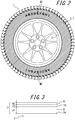
- FIG. 2 is a side view of a tire-rim assembly in which a pneumatic tire is mounted to an applicable rim according to one of embodiments of the present disclosure.
- the tire 1 is mounted to an applicable rim R, and the tire 1 includes, on an outer surface 3a of the sidewall portion 3, an annular decorative portion 7 in the illustrated example.
- markings M1 and M2 which include alphabets, are applied to two positions on a circumference of the decorative portion 7.
- the decorative portion 7 may also be provided partially on the circumference of sidewall portion 3.
- the decorative portion 7 may be provided in the two positions to which the markings M1 and M2 are applied.
- FIG. 3 is a partial sectional view schematically illustrating the decorative portion 7 and the sidewall portion 3.
- the decorative portion 7 includes a print layer 8 and a protective layer 9, which is located on the tire outer side of the print layer 8 to protect the print layer 8 against external damage.
- the decorative portion 7 further includes an intermediate layer 10, which is located between the print layer 8 and the protective layer 9.
- the print layer 8 may be formed by applying paint, such as ink, to the outer surface 3a of the sidewall portion 3 by screen printing, ink jet printing, relief printing, or another printing process.
- the print layer 8 may have a laminated structure of a white-paint layer and a color-paint layer (in any color other than white) disposed on the tire outer side of the white-paint layer. To produce the decorative portion 7 with excellent color density, it is preferable to make the white-paint layer thicker than the color-paint layer.
- the above laminated structure may be applied to an entirety or part of the circumference of the print layer 8.
- the color-paint layer may be laminated directly on a surface of the white-paint layer or may be formed via a primer layer.
- the print layer 8 and a rubber layer (side rubber) constituting the sidewall portion 3 may be in direct contact or may be in contact via a primer layer.
- the primer layer may be made of the same material as the intermediate layer 10. This omits the need for preparing individual materials (such as inks) and reduces cost.
- the intermediate layer 10 and the protective layer 9 are formed as transparent layers so that the print layer 8 is visible.
- a storage modulus of the print layer 8 a storage modulus of the protective layer 9, and a storage modulus of the intermediate layer 10 are respectively defined as E1', E2', and E3'
- the pneumatic tire of the present embodiment satisfies the following relational expression: E 2 ⁇ > E 3 ⁇ > E 1 ⁇ .
- one possible way to increase resistance to external damage of the decorative portion 7 is to use the protective layer 9 having a high storage modulus.
- a great difference in rigidity between the protective layer 9 and the print layer 8 might lead to occurrence of cracks at an interface therebetween due to strain of the tire, a rubber article.
- the intermediate layer 10, which has a storage modulus satisfying the above relational expression is disposed between the print layer 8 and the protective layer 9, the difference in rigidity from the print layer 8 to the protective layer 9 is mitigated.
- the present embodiment improves durability of the decorative portion 7, while disposing the protective layer 9, which has a storage modulus sufficient for resistance to external damage to be demonstrated.
- durability and resistance to external damage of the decorative portion in the sidewall portion are improved.
- the ratio E2' / E3' and the ratio E3' / E1' preferably satisfy the following relational expression: E 2 ⁇ / E 3 ⁇ ⁇ E 3 ⁇ / E 1 ⁇ .
- the ratio E3' / E1' of the storage modulus of the intermediate layer 10 to the storage modulus of the print layer 8, on the side in which the storage moduli are high is set to be greater than the ratio E2' / E3' of the storage modulus of the protective layer 9 to the storage modulus of the intermediate layer 10, on the side in which the storage moduli are low. Consequently, durability and resistance to external damage of the decorative portion 7 as a whole is further improved.
- the ratio E2' / E1' preferably satisfies the following relational expression: E 2 ⁇ / E 1 ⁇ ⁇ 5.
- the above ratio E2' / E1' preferably satisfies the following relational expression: E 2 ⁇ / E 1 ⁇ ⁇ 100.
- the print layer 8 and the intermediate layer 10 are even better adaptive to strain of side rubber caused especially by deformation of the sidewall portion 3 of the tire, and durability of the decorative portion 7 is even further improved.
- the storage modulus E1' of the print layer 8 is preferably 1.0 ⁇ 10 8 (Pa) or less, and the storage modulus E2' of the protective layer 9 is preferably 1.0 ⁇ 10 7 (Pa) or more.
- the storage modulus E1' of the print layer 8 is preferably 1.0 ⁇ 10 6 (Pa) or more, and the storage modulus E2' of the protective layer 9 is preferably 5.0 ⁇ 10 8 (Pa) or less.
- examples of materials of the print layer 8 may include, but not particularly limited to, active energy ray curing ink that is composed mainly of oligomer, monomer, and a coloring agent and that also contains, as needed, a photopolymerization initiator, an ultraviolet absorbing agent, an antioxidant, a light stabilizer, an adhesion promoter, a rheology control agent, a dispersant, or the like.
- the storage modulus E1' of the print layer 8 may be regulated to be within a predetermined range by controlling the amounts of the above materials.
- UF-245 ink series manufactured by DNP Fine Chemicals Co., Ltd. may be used as materials of the print layer 8.
- Examples of materials of the protective layer 9 may include, but not particularly limited to, (meth)acrylic acid-based resin or resin obtained by silicone-modification of (meth)acrylic acid-based resin. In addition to such resin, urethane-based resin or any resin containing resin obtained by carbonate-modification of urethane-based resin may also be used.
- materials of the protective layer 9 for example, "OP-SA13", “OP-SA79”, “OP-SA355", and "OP-SA356" manufactured by DNP Fine Chemicals Co., Ltd. may be considered as (meth)acrylic acid-based resin or resin obtained by silicone-modification of (meth)acrylic acid-based resin, and "OP-U354" manufactured by DNP Fine Chemicals Co., Ltd.
- the storage modulus E2' of the protective layer 9 may be regulated to be within a predetermined range by controlling the amounts of the above materials.
- materials of the intermediate layer 10 may include, but not particularly limited to, active energy ray curing ink for forming the intermediate layer that is composed mainly of oligomer and monomer and that also contains, as needed, a photopolymerization initiator, an ultraviolet absorbing agent, an antioxidant, a light stabilizer, an adhesion promoter, a theology control agent, or the like.
- active energy ray curing ink for forming the intermediate layer that is composed mainly of oligomer and monomer and that also contains, as needed, a photopolymerization initiator, an ultraviolet absorbing agent, an antioxidant, a light stabilizer, an adhesion promoter, a theology control agent, or the like.
- UF-64 ink series manufactured by DNP Fine Chemicals Co., Ltd.
- an active energy ray may include an ⁇ -ray, a ⁇ -ray, an X-ray, an ultraviolet ray, and an electron beam.
- a thickness d1 of the print layer 8 is preferably greater than a thickness d2 of the protective layer 9 and a thickness d3 of the intermediate layer 10.
- the thickness of the print layer 8 which has the lowest storage modulus and is softest, greatest of all, flexibility of the decorative portion 7 as a whole is improved, and durability of the decorative portion 7 is even further improved.
- the ratio d2 / d1 and the ratio d3 / d1 preferably satisfy the following relational expressions: d 2 / d 1 ⁇ 1 / 2 ; d 3 / d 1 ⁇ 1 / 2.
- a total sum (d2 + d3) of the thickness d2 of the protective layer 9 and the thickness d3 of the intermediate layer 10 is preferably 1 / 2 or less the thickness d1 of the print layer 8.
- the thickness d1 of the print layer 8 is preferably from 30 to 60 ⁇ m
- the thickness d2 of the protective layer 9 is preferably from 10 to 15 ⁇ m
- the thickness d3 of the intermediate layer 10 is preferably from 10 to 20 ⁇ m.
- the contrast ratio of the intermediate layer 10 is preferably less than the contrast ratio of the print layer 8 and the contrast ratio of the protective layer 9.
- Reducing the contrast ratio of the intermediate layer 10 creates a catch due to microscopic irregularities and accordingly, further improves adhesiveness between the intermediate layer 10 and the print layer 8. Furthermore, at an interface between the intermediate layer 10 and the print layer 8, a region over which paint is not applied microscopically is created, and strain is released. Accordingly, durability of the decorative portion 7 is further improved.
- tires according to Examples 1 to 5 and a tire according to Comparative Example 1 were experimentally produced and each tested for evaluating durability and resistance to external damage of the decorative portion.
- the tires each have the common internal structure as illustrated in FIG. 1 and include, on the outer surface of the sidewall portion, the decorative portion including the print layer, the protective layer, and the intermediate layer.
- the tires have specifications shown in Table 1 below and are common in terms of other specifications not listed in Table 1.
- Each tire was mounted to an applicable rim, filled with a prescribed internal pressure, and installed on a vehicle. Then, after driven for 20,000 km on the actual vehicle, each tire was tested to measure the length of a crack occurring in the decorative portion for evaluating durability of the decorative portion. The evaluation is expressed as an index value, with the result for the tire according to Comparative Example 1 as 100. A larger value indicates better durability of the decorative portion (i.e., a shorter length of crack).
- the decorative portion was subjected to a scratch test with a coin under a load condition of 1200 g, and according to the number of scratches observed when peeling occurred in the decorative portion, resistance to external damage of the decorative portion was evaluated.
- the evaluation is expressed as an index value, with the result for the tire according to Comparative Example 1 as 100. A larger value indicates better resistance to external damage of the decorative portion (i.e., a greater number of scratches observed before peeling).
- Example 1 shows that Example 1, which satisfies the relational expression E2' / E3' ⁇ E3' / E1', is superior in durability and resistance to external damage of the decorative portion to Example 2.
- a comparison of Example 1 and Example 3 also shows that Example 1, which satisfies the relational expression E2' / E1' ⁇ 5, is superior in durability of the decorative portion to Example 3.
- a comparison of Example 1 and Example 4 shows that Example 1, which satisfies the relational expression d1 > d2, d3, is superior in durability of the decorative portion to Example 4.
- Example 1 which satisfies the relational expressions d2 / d1 ⁇ 1 / 2 and d3 / d1 ⁇ 1 / 2, is superior in durability of the decorative portion to Example 5.
Landscapes
- Engineering & Computer Science (AREA)
- Mechanical Engineering (AREA)
- Tires In General (AREA)
Abstract
Description
- The present disclosure relates to a pneumatic tire.
- There have been proposed a variety of pneumatic tires (hereinafter, may be simply called tires) provided, on an outer surface of a sidewall portion thereof, with a decorative portion formed by an annular or other shaped print layer (refer to, for example, Patent Literature 1).
- PL1:
JP2013237292A - In the above regard, when the decorative portion formed by the print layer as described above is provided in a tire, cracks may occur in the decorative portion due to strain caused by deformation of the tire during running. Accordingly, there is a need for improving durability of the decorative portion. Furthermore, the print layer may peel off when the tire contacts a curbstone or the like. Accordingly, there is also a need for improving resistance to external damage of the decorative portion including the print layer.
- The present disclosure has been conceived in light of the above problems, and the present disclosure is to provide a pneumatic tire in which durability and resistance to external damage of the decorative portion in the sidewall portion are improved.
- A summary of the present disclosure is as follows.
- A pneumatic tire including, on an outer surface of a sidewall portion thereof, a decorative portion including a print layer and a protective layer located on a tire outer side of the print layer, wherein
the decorative portion further includes an intermediate layer located between the print layer and the protective layer, and
when a storage modulus of the print layer, a storage modulus of the protective layer, and a storage modulus of the intermediate layer are respectively defined as E1', E2', and E3', the following relational expression is satisfied:
- Herein, a "storage modulus" refers to a storage modulus that is measured at 25 °C according to JIS K7244.
- A "thickness of layer" herein refers to a thickness that is measured at a maximum width position of the layer and measured when the tire is mounted to an applicable rim, filled with a predetermined internal pressure, and placed under no load. Herein, an "applicable rim" refers to any of rims specified in industrial standards valid in respective regions where tires are manufactured and used. Examples of such industrial standards include Japan Automobile Tire Manufacturers Association (JATMA) YEAR BOOK in Japan, European Tire and Rim Technical Organization (ETRTO) STANDARDS MANUAL in Europe, and the TIRE and RIM ASSOCIATION INC. (TRA) YEAR BOOK in the United States. A "prescribed internal pressure" refers to an air pressure (maximum air pressure corresponding to a tire maximum load capacity for a tire of applicable size as specified in JATMA or other standards.
- Herein, a "contrast ratio" described below refers to a paint area per unit area on a tire surface and may be obtained, for example, by measuring an area over which paint is applied through image processing with a microscope.
- The present disclosure provides a pneumatic tire in which durability and resistance to external damage of the decorative portion in the sidewall portion are improved.
- In the accompanying drawings:
-
FIG. 1 is a sectional view in a tire width direction of a pneumatic tire according to one of embodiments of the present disclosure; -
FIG. 2 is a side view of a tire-rim assembly in which a pneumatic tire is mounted to a rim according to one of embodiments of the present disclosure; and -
FIG. 3 is a partial sectional view schematically illustrating a decorative portion and a sidewall portion. - Hereinafter, embodiments of the present disclosure will be described in detail for illustration with reference to the drawings.
-
FIG. 1 is a sectional view in a tire width direction of a pneumatic tire according to one of embodiments of the present disclosure. AlthoughFIG. 1 illustrates only a half portion in the tire width direction that is demarcated by a tire equatorial plane CL as a boundary, the other half portion in the tire width direction, which is not illustrated, has the same structure. As illustrated inFIG. 1 , the pneumatic tire 1 includes anannular tread portion 2, which extends continuously in a tire circumferential direction, a pair of sidewall portions 3 (with only one of thesidewall portions 3 illustrated inFIG. 1 ), which extends contiguously with sides of thetread portion 2 toward an inner side in a tire radial direction, and a pair of bead portions 4 (with only one of thebead portions 4 illustrated inFIG. 1 ), which is contiguous with inner sides in the tire radial direction of theside wall portions 3. Herein, although an internal structure of the tire is not particularly limited, the tire 1 in an example ofFIG. 1 includes acarcass 5, which extends toroidally between a pair ofbead cores 4a (with only one of thebead cores 4a illustrated inFIG. 1 ) embedded in thebead portions 4, and abelt 6, which is disposed on the outer side in the tire radial direction of thecarcass 5 and which includes two belt layers in this example. -
FIG. 2 is a side view of a tire-rim assembly in which a pneumatic tire is mounted to an applicable rim according to one of embodiments of the present disclosure. As illustrated inFIG. 2 , the tire 1 is mounted to an applicable rim R, and the tire 1 includes, on anouter surface 3a of thesidewall portion 3, an annular decorative portion 7 in the illustrated example. In the illustrated example, markings M1 and M2, which include alphabets, are applied to two positions on a circumference of the decorative portion 7. Additionally, the decorative portion 7 may also be provided partially on the circumference ofsidewall portion 3. For example, the decorative portion 7 may be provided in the two positions to which the markings M1 and M2 are applied. - Reference is next made to
FIG. 3 , which is a partial sectional view schematically illustrating the decorative portion 7 and thesidewall portion 3. As illustrated inFIG. 3 , the decorative portion 7 includes aprint layer 8 and aprotective layer 9, which is located on the tire outer side of theprint layer 8 to protect theprint layer 8 against external damage. The decorative portion 7 further includes anintermediate layer 10, which is located between theprint layer 8 and theprotective layer 9. - In the present embodiment herein, the
print layer 8 may be formed by applying paint, such as ink, to theouter surface 3a of thesidewall portion 3 by screen printing, ink jet printing, relief printing, or another printing process. - The
print layer 8 may have a laminated structure of a white-paint layer and a color-paint layer (in any color other than white) disposed on the tire outer side of the white-paint layer. To produce the decorative portion 7 with excellent color density, it is preferable to make the white-paint layer thicker than the color-paint layer. The above laminated structure may be applied to an entirety or part of the circumference of theprint layer 8. The color-paint layer may be laminated directly on a surface of the white-paint layer or may be formed via a primer layer. - Furthermore, the
print layer 8 and a rubber layer (side rubber) constituting thesidewall portion 3 may be in direct contact or may be in contact via a primer layer. When theprint layer 8 is disposed on the tire outer side of the tire side rubber via the primer layer, the primer layer may be made of the same material as theintermediate layer 10. This omits the need for preparing individual materials (such as inks) and reduces cost. - In the present embodiment, the
intermediate layer 10 and theprotective layer 9 are formed as transparent layers so that theprint layer 8 is visible. - Meanwhile, when a storage modulus of the
print layer 8, a storage modulus of theprotective layer 9, and a storage modulus of theintermediate layer 10 are respectively defined as E1', E2', and E3', the pneumatic tire of the present embodiment satisfies the following relational expression:
- The following describes effects of the pneumatic tire of the present embodiment.
- First of all, one possible way to increase resistance to external damage of the decorative portion 7 is to use the
protective layer 9 having a high storage modulus. However, a great difference in rigidity between theprotective layer 9 and theprint layer 8 might lead to occurrence of cracks at an interface therebetween due to strain of the tire, a rubber article. In the present embodiment, since theintermediate layer 10, which has a storage modulus satisfying the above relational expression, is disposed between theprint layer 8 and theprotective layer 9, the difference in rigidity from theprint layer 8 to theprotective layer 9 is mitigated. Accordingly, the present embodiment improves durability of the decorative portion 7, while disposing theprotective layer 9, which has a storage modulus sufficient for resistance to external damage to be demonstrated. Thus, according to the tire of the present disclosure, durability and resistance to external damage of the decorative portion in the sidewall portion are improved. - In the above regard, in the pneumatic tire according to the present disclosure, the ratio E2' / E3' and the ratio E3' / E1' preferably satisfy the following relational expression:

- The aforementioned difference in rigidity tends to be relatively mitigated in the presence of a soft layer like the
print layer 8. Accordingly, the ratio E3' / E1' of the storage modulus of theintermediate layer 10 to the storage modulus of theprint layer 8, on the side in which the storage moduli are high, is set to be greater than the ratio E2' / E3' of the storage modulus of theprotective layer 9 to the storage modulus of theintermediate layer 10, on the side in which the storage moduli are low. Consequently, durability and resistance to external damage of the decorative portion 7 as a whole is further improved. - Furthermore, in the pneumatic tire according to the present disclosure, the ratio E2' / E1' preferably satisfies the following relational expression:

- Setting the ratio E2' / E1' to be 5 or more allows function dissociation in which resistance to external damage is improved in the
protective layer 9, which has a high storage modulus, and durability is maintained in theprint layer 8, which has a low storage modulus. Accordingly, durability and resistance to external damage of the decorative portion 7 are even further improved. - Additionally, from the perspective of maintaining durability of the decorative portion 7 by preventing an excessive difference in rigidity from the
protective layer 9 to theprint layer 8, the above ratio E2' / E1' preferably satisfies the following relational expression:
- Moreover, in the pneumatic tire according to the present disclosure, when a storage modulus of side rubber (rubber constituting the sidewall portion 3) that is adjacent to the tire inner side of the decorative portion 7 is defined as E4', the following relational expressions are preferably satisfied:


- When the above relational expressions are satisfied, the
print layer 8 and theintermediate layer 10 are even better adaptive to strain of side rubber caused especially by deformation of thesidewall portion 3 of the tire, and durability of the decorative portion 7 is even further improved. - In more detail, from the perspective of improving resistance to external damage in the
protective layer 9, which has a high storage modulus, and maintaining durability in theprint layer 8, which has a low storage modulus, the storage modulus E1' of theprint layer 8 is preferably 1.0 × 10⁸ (Pa) or less, and the storage modulus E2' of theprotective layer 9 is preferably 1.0 × 10⁷ (Pa) or more. - On the other hand, from the perspective of maintaining durability of the decorative portion 7 by preventing an excessive difference in rigidity from the
protective layer 9 to theprint layer 8, the storage modulus E1' of theprint layer 8 is preferably 1.0 × 10⁶ (Pa) or more, and the storage modulus E2' of theprotective layer 9 is preferably 5.0 × 10⁸ (Pa) or less. - In the present disclosure herein, examples of materials of the
print layer 8 may include, but not particularly limited to, active energy ray curing ink that is composed mainly of oligomer, monomer, and a coloring agent and that also contains, as needed, a photopolymerization initiator, an ultraviolet absorbing agent, an antioxidant, a light stabilizer, an adhesion promoter, a rheology control agent, a dispersant, or the like. The storage modulus E1' of theprint layer 8 may be regulated to be within a predetermined range by controlling the amounts of the above materials. In more detail, for example, UF-245 ink series manufactured by DNP Fine Chemicals Co., Ltd. may be used as materials of theprint layer 8. Examples of materials of theprotective layer 9 may include, but not particularly limited to, (meth)acrylic acid-based resin or resin obtained by silicone-modification of (meth)acrylic acid-based resin. In addition to such resin, urethane-based resin or any resin containing resin obtained by carbonate-modification of urethane-based resin may also be used. In more detail, as materials of theprotective layer 9, for example, "OP-SA13", "OP-SA79", "OP-SA355", and "OP-SA356" manufactured by DNP Fine Chemicals Co., Ltd. may be considered as (meth)acrylic acid-based resin or resin obtained by silicone-modification of (meth)acrylic acid-based resin, and "OP-U354" manufactured by DNP Fine Chemicals Co., Ltd. may be considered as urethane-based resin or resin obtained by carbonate-modification of urethane-based resin. The storage modulus E2' of theprotective layer 9 may be regulated to be within a predetermined range by controlling the amounts of the above materials. Examples of materials of theintermediate layer 10 may include, but not particularly limited to, active energy ray curing ink for forming the intermediate layer that is composed mainly of oligomer and monomer and that also contains, as needed, a photopolymerization initiator, an ultraviolet absorbing agent, an antioxidant, a light stabilizer, an adhesion promoter, a theology control agent, or the like. In more detail, for example, UF-64 ink series manufactured by DNP Fine Chemicals Co., Ltd. may be used as materials of theintermediate layer 10. The storage modulus E3' of theintermediate layer 10 may be regulated to be within a predetermined range by controlling the amounts of the above materials. Additionally, examples of an active energy ray may include an α-ray, a γ-ray, an X-ray, an ultraviolet ray, and an electron beam. - In the pneumatic tire according to the present disclosure, a thickness d1 of the
print layer 8 is preferably greater than a thickness d2 of theprotective layer 9 and a thickness d3 of theintermediate layer 10. - By making the thickness of the
print layer 8, which has the lowest storage modulus and is softest, greatest of all, flexibility of the decorative portion 7 as a whole is improved, and durability of the decorative portion 7 is even further improved. - In the above regard, in the pneumatic tire according to the present disclosure, the ratio d2 / d1 and the ratio d3 / d1 preferably satisfy the following relational expressions:


- By increasing the thickness of the
print layer 8, which has the smallest storage modulus, so that the above relational expressions are satisfied, strain of the tire is received by theprint layer 8. Consequently, durability of the decorative portion 7 is even further improved. - For the same reason, a total sum (d2 + d3) of the thickness d2 of the
protective layer 9 and the thickness d3 of theintermediate layer 10 is preferably 1 / 2 or less the thickness d1 of theprint layer 8. - For example, to further ensure both durability and resistance to external damage of the decorative portion 7, the thickness d1 of the
print layer 8 is preferably from 30 to 60 µm, the thickness d2 of theprotective layer 9 is preferably from 10 to 15 µm, and the thickness d3 of theintermediate layer 10 is preferably from 10 to 20 µm. - Moreover, in the pneumatic tire according to the present disclosure, the contrast ratio of the
intermediate layer 10 is preferably less than the contrast ratio of theprint layer 8 and the contrast ratio of theprotective layer 9. - Reducing the contrast ratio of the
intermediate layer 10 creates a catch due to microscopic irregularities and accordingly, further improves adhesiveness between theintermediate layer 10 and theprint layer 8. Furthermore, at an interface between theintermediate layer 10 and theprint layer 8, a region over which paint is not applied microscopically is created, and strain is released. Accordingly, durability of the decorative portion 7 is further improved. - To confirm the effects of the present disclosure, tires according to Examples 1 to 5 and a tire according to Comparative Example 1 were experimentally produced and each tested for evaluating durability and resistance to external damage of the decorative portion. The tires each have the common internal structure as illustrated in
FIG. 1 and include, on the outer surface of the sidewall portion, the decorative portion including the print layer, the protective layer, and the intermediate layer. The tires have specifications shown in Table 1 below and are common in terms of other specifications not listed in Table 1. - Each tire was mounted to an applicable rim, filled with a prescribed internal pressure, and installed on a vehicle. Then, after driven for 20,000 km on the actual vehicle, each tire was tested to measure the length of a crack occurring in the decorative portion for evaluating durability of the decorative portion. The evaluation is expressed as an index value, with the result for the tire according to Comparative Example 1 as 100. A larger value indicates better durability of the decorative portion (i.e., a shorter length of crack).
- For each of the tires, the decorative portion was subjected to a scratch test with a coin under a load condition of 1200 g, and according to the number of scratches observed when peeling occurred in the decorative portion, resistance to external damage of the decorative portion was evaluated. The evaluation is expressed as an index value, with the result for the tire according to Comparative Example 1 as 100. A larger value indicates better resistance to external damage of the decorative portion (i.e., a greater number of scratches observed before peeling).
- The evaluation results are shown in Table 1 below.
[Table 1] Example 1 Example 2 Example3 3Example 4 Example 5 Comparative Example 1 E1'(Pa) 9.8 × 10⁵ 9.8 × 10⁵ 4.2 × 10⁶ 9.8 × 10⁵ 9.8 × 10⁵ 4.2 × 10⁶ E2'(Pa) 2.0 × 10⁷ 2.0 × 10⁷ 2.0 × 10⁷ 2.0 × 10⁷ 2.0 × 10⁷ 1.6E + 08 E3'(Pa) 4.9 × 10⁶ 1.1 × 10⁶ 4.9 × 10⁶ 4.9 × 10⁶ 4.9 × 10⁶ - E4'(Pa) 4.8 × 10⁷ 4.8 × 10⁷ 4.8 × 10⁷ 4.8 × 10⁷ 4.8 × 10⁷ 4.8 × 10⁷ E2' > E3' > E1' Satisfied Satisfied Satisfied Satisfied Satisfied - E2'/E3'<E3'/E1' Satisfied Unsatisfied Unsatisfied Satisfied Satisfied - E2'/E1' ≥ 5 Satisfied Satisfied Unsatisfied Satisfied Satisfied Satisfied E1'< E4' and E3' < E4' Satisfied Satisfied Satisfied Satisfied Satisfied - d1 (µm) 40 40 40 40 40 40 d2 (µm) 15 15 15 50 30 15 d3 (µm) 10 10 10 10 10 - d1 > d2. d3 Satisfied Satisfied Satisfied Unsatisfied Satisfied - d2/d1 ≤ 1/2 and d3 /d1 ≤ 1/2 Satisfied Satisfied Satisfied Satisfied Unsatisfied - Contrast ratio of intermediate layer < contrast ratio of print layer, contrast ratio of protective layer Satisfied Satisfied Satisfied Satisfied Satisfied - Durability of decorative portion 250000 83333 83333 50000 50000 100 Resistance to external damage of decorative portion 1000 400 1000 667 500 100 - As can be seen from Table 1, the tires according to Examples 1 to 5 are superior in durability and resistance to external damage of the decorative portion to the tire according to Comparative Example 1. Furthermore, a comparison of Example 1 and Example 2 shows that Example 1, which satisfies the relational expression E2' / E3' < E3' / E1', is superior in durability and resistance to external damage of the decorative portion to Example 2. A comparison of Example 1 and Example 3 also shows that Example 1, which satisfies the relational expression E2' / E1' ≥ 5, is superior in durability of the decorative portion to Example 3. Moreover, a comparison of Example 1 and Example 4 shows that Example 1, which satisfies the relational expression d1 > d2, d3, is superior in durability of the decorative portion to Example 4. A comparison of Example 1 and Example 5 also shows that Example 1, which satisfies the relational expressions d2 / d1 ≤ 1 / 2 and d3 / d1 ≤ 1 / 2, is superior in durability of the decorative portion to Example 5.
-
- 1
- Pneumatic tire
- 2
- Tread portion
- 3
- Sidewall portion
- 4
- Bead portion
- 4a
- Bead core
- 5
- Carcass
- 6
- Belt
- 7
- Decorative portion
- 8
- Print layer
- 9
- Protective layer
- 10
- Intermediate layer
Claims (7)
- A pneumatic tire comprising, on an outer surface of a sidewall portion thereof, a decorative portion including a print layer and a protective layer located on a tire outer side of the print layer, wherein
the decorative portion further includes an intermediate layer located between the print layer and the protective layer, and
when a storage modulus of the print layer, a storage modulus of the protective layer, and a storage modulus of the intermediate layer are respectively defined as E1', E2', and E3', the following relational expression is satisfied:
- The pneumatic tire according to claim 1, wherein a thickness d1 of the print layer is greater than a thickness d2 of the protective layer and a thickness d3 of the intermediate layer.
- The pneumatic tire according to claim 1 or 2, wherein the following relational expression is satisfied:

- The pneumatic tire according to any one of claims 1 to 3, wherein the following relational expression is satisfied:

- The pneumatic tire according to any one of claims 1 to 4, wherein a thickness d1 of the print layer, a thickness d2 of the protective layer, and a thickness d3 of the intermediate layer satisfy the following relational expressions:


- The pneumatic tire according to any one of claims 1 to 5, wherein a contrast ratio of the intermediate layer is less than a contrast ratio of the print layer and a contrast ratio of the protective layer.
- The pneumatic tire according to any one of claims 1 to 6, wherein, when a storage modulus of side rubber adjacent to the decorative portion is defined as E4', the following relational expressions are satisfied:


Applications Claiming Priority (2)
| Application Number | Priority Date | Filing Date | Title |
|---|---|---|---|
| JP2014163064A JP6349198B2 (en) | 2014-08-08 | 2014-08-08 | Pneumatic tire |
| PCT/JP2015/003727 WO2016021138A1 (en) | 2014-08-08 | 2015-07-24 | Pneumatic tire |
Publications (3)
| Publication Number | Publication Date |
|---|---|
| EP3196052A1 true EP3196052A1 (en) | 2017-07-26 |
| EP3196052A4 EP3196052A4 (en) | 2017-08-09 |
| EP3196052B1 EP3196052B1 (en) | 2018-05-09 |
Family
ID=55263435
Family Applications (1)
| Application Number | Title | Priority Date | Filing Date |
|---|---|---|---|
| EP15830600.1A Active EP3196052B1 (en) | 2014-08-08 | 2015-07-24 | Pneumatic tire |
Country Status (5)
| Country | Link |
|---|---|
| US (1) | US10787041B2 (en) |
| EP (1) | EP3196052B1 (en) |
| JP (1) | JP6349198B2 (en) |
| CN (1) | CN106660411B (en) |
| WO (1) | WO2016021138A1 (en) |
Families Citing this family (1)
| Publication number | Priority date | Publication date | Assignee | Title |
|---|---|---|---|---|
| IT201800006206A1 (en) * | 2018-06-11 | 2019-12-11 | TIRE FOR VEHICLE WHEELS |
Family Cites Families (11)
| Publication number | Priority date | Publication date | Assignee | Title |
|---|---|---|---|---|
| US3607498A (en) * | 1967-05-17 | 1971-09-21 | Matsushita Electric Industrial Co Ltd | Method of producing tires having decorative sidewalls |
| JP2971545B2 (en) * | 1990-09-11 | 1999-11-08 | 株式会社ブリヂストン | Pneumatic tire having a colored decorative part and a method of manufacturing the same |
| JP4282138B2 (en) * | 1998-10-12 | 2009-06-17 | 横浜ゴム株式会社 | tire |
| JP2007210378A (en) * | 2006-02-08 | 2007-08-23 | Keiji Iimura | Light emitting tire |
| WO2007121473A1 (en) * | 2006-04-18 | 2007-10-25 | Treadfx Llc | Production of a tire with printable thermoplastic organic polymer |
| JP5422919B2 (en) * | 2008-05-21 | 2014-02-19 | 横浜ゴム株式会社 | Tire label |
| KR101793884B1 (en) | 2010-08-31 | 2017-11-03 | 다이니폰 인사츠 가부시키가이샤 | Intermediate transfer medium |
| JP2013136332A (en) * | 2011-12-28 | 2013-07-11 | Bridgestone Corp | Tire |
| JP6058891B2 (en) * | 2012-01-12 | 2017-01-11 | 株式会社Dnpファインケミカル | Decorative tire and manufacturing method thereof |
| JP5977577B2 (en) | 2012-05-11 | 2016-08-24 | 株式会社ブリヂストン | Tire / rim wheel assembly |
| JP2016043889A (en) * | 2014-08-26 | 2016-04-04 | 株式会社ブリヂストン | tire |
-
2014
- 2014-08-08 JP JP2014163064A patent/JP6349198B2/en active Active
-
2015
- 2015-07-24 EP EP15830600.1A patent/EP3196052B1/en active Active
- 2015-07-24 WO PCT/JP2015/003727 patent/WO2016021138A1/en not_active Ceased
- 2015-07-24 US US15/502,269 patent/US10787041B2/en active Active
- 2015-07-24 CN CN201580042399.2A patent/CN106660411B/en active Active
Also Published As
| Publication number | Publication date |
|---|---|
| JP6349198B2 (en) | 2018-06-27 |
| WO2016021138A1 (en) | 2016-02-11 |
| CN106660411A (en) | 2017-05-10 |
| EP3196052A4 (en) | 2017-08-09 |
| US20170240002A1 (en) | 2017-08-24 |
| EP3196052B1 (en) | 2018-05-09 |
| US10787041B2 (en) | 2020-09-29 |
| JP2016037247A (en) | 2016-03-22 |
| CN106660411B (en) | 2018-10-26 |
Similar Documents
| Publication | Publication Date | Title |
|---|---|---|
| JP5507015B2 (en) | tire | |
| US10239353B2 (en) | Pneumatic tire | |
| EP2848432B1 (en) | Heavy duty tire | |
| US20230241931A1 (en) | Pneumatic tire | |
| EP2772368B1 (en) | Heavy load pneumatic radial tire | |
| EP2570274A1 (en) | Pneumatic tire | |
| AU2016336312A1 (en) | Pneumatic tire | |
| EP2641752B1 (en) | Pneumatic tire | |
| EP3135507B1 (en) | Side-reinforced run-flat radial tire | |
| EP3196052B1 (en) | Pneumatic tire | |
| EP3178670B1 (en) | Pneumatic tire | |
| EP3015292B1 (en) | Tire | |
| US20220339970A1 (en) | Pneumatic tire | |
| JP6406918B2 (en) | Pneumatic tire | |
| EP3473453B1 (en) | Heavy duty pneumatic tire | |
| EP4357156A1 (en) | Radial tire for aircraft | |
| WO2016031141A1 (en) | Tire | |
| JP2019001374A (en) | Pneumatic tire |
Legal Events
| Date | Code | Title | Description |
|---|---|---|---|
| PUAI | Public reference made under article 153(3) epc to a published international application that has entered the european phase |
Free format text: ORIGINAL CODE: 0009012 |
|
| 17P | Request for examination filed |
Effective date: 20170224 |
|
| AK | Designated contracting states |
Kind code of ref document: A1 Designated state(s): AL AT BE BG CH CY CZ DE DK EE ES FI FR GB GR HR HU IE IS IT LI LT LU LV MC MK MT NL NO PL PT RO RS SE SI SK SM TR |
|
| AX | Request for extension of the european patent |
Extension state: BA ME |
|
| A4 | Supplementary search report drawn up and despatched |
Effective date: 20170707 |
|
| RIC1 | Information provided on ipc code assigned before grant |
Ipc: B60C 13/00 20060101AFI20170704BHEP |
|
| DAV | Request for validation of the european patent (deleted) | ||
| DAX | Request for extension of the european patent (deleted) | ||
| GRAP | Despatch of communication of intention to grant a patent |
Free format text: ORIGINAL CODE: EPIDOSNIGR1 |
|
| INTG | Intention to grant announced |
Effective date: 20171120 |
|
| GRAS | Grant fee paid |
Free format text: ORIGINAL CODE: EPIDOSNIGR3 |
|
| GRAA | (expected) grant |
Free format text: ORIGINAL CODE: 0009210 |
|
| AK | Designated contracting states |
Kind code of ref document: B1 Designated state(s): AL AT BE BG CH CY CZ DE DK EE ES FI FR GB GR HR HU IE IS IT LI LT LU LV MC MK MT NL NO PL PT RO RS SE SI SK SM TR |
|
| REG | Reference to a national code |
Ref country code: GB Ref legal event code: FG4D |
|
| REG | Reference to a national code |
Ref country code: CH Ref legal event code: EP Ref country code: AT Ref legal event code: REF Ref document number: 997236 Country of ref document: AT Kind code of ref document: T Effective date: 20180515 |
|
| REG | Reference to a national code |
Ref country code: IE Ref legal event code: FG4D |
|
| REG | Reference to a national code |
Ref country code: DE Ref legal event code: R096 Ref document number: 602015011037 Country of ref document: DE |
|
| REG | Reference to a national code |
Ref country code: FR Ref legal event code: PLFP Year of fee payment: 4 |
|
| REG | Reference to a national code |
Ref country code: NL Ref legal event code: MP Effective date: 20180509 |
|
| REG | Reference to a national code |
Ref country code: LT Ref legal event code: MG4D |
|
| PG25 | Lapsed in a contracting state [announced via postgrant information from national office to epo] |
Ref country code: FI Free format text: LAPSE BECAUSE OF FAILURE TO SUBMIT A TRANSLATION OF THE DESCRIPTION OR TO PAY THE FEE WITHIN THE PRESCRIBED TIME-LIMIT Effective date: 20180509 Ref country code: NO Free format text: LAPSE BECAUSE OF FAILURE TO SUBMIT A TRANSLATION OF THE DESCRIPTION OR TO PAY THE FEE WITHIN THE PRESCRIBED TIME-LIMIT Effective date: 20180809 Ref country code: LT Free format text: LAPSE BECAUSE OF FAILURE TO SUBMIT A TRANSLATION OF THE DESCRIPTION OR TO PAY THE FEE WITHIN THE PRESCRIBED TIME-LIMIT Effective date: 20180509 Ref country code: ES Free format text: LAPSE BECAUSE OF FAILURE TO SUBMIT A TRANSLATION OF THE DESCRIPTION OR TO PAY THE FEE WITHIN THE PRESCRIBED TIME-LIMIT Effective date: 20180509 Ref country code: SE Free format text: LAPSE BECAUSE OF FAILURE TO SUBMIT A TRANSLATION OF THE DESCRIPTION OR TO PAY THE FEE WITHIN THE PRESCRIBED TIME-LIMIT Effective date: 20180509 Ref country code: BG Free format text: LAPSE BECAUSE OF FAILURE TO SUBMIT A TRANSLATION OF THE DESCRIPTION OR TO PAY THE FEE WITHIN THE PRESCRIBED TIME-LIMIT Effective date: 20180809 |
|
| PG25 | Lapsed in a contracting state [announced via postgrant information from national office to epo] |
Ref country code: NL Free format text: LAPSE BECAUSE OF FAILURE TO SUBMIT A TRANSLATION OF THE DESCRIPTION OR TO PAY THE FEE WITHIN THE PRESCRIBED TIME-LIMIT Effective date: 20180509 Ref country code: RS Free format text: LAPSE BECAUSE OF FAILURE TO SUBMIT A TRANSLATION OF THE DESCRIPTION OR TO PAY THE FEE WITHIN THE PRESCRIBED TIME-LIMIT Effective date: 20180509 Ref country code: LV Free format text: LAPSE BECAUSE OF FAILURE TO SUBMIT A TRANSLATION OF THE DESCRIPTION OR TO PAY THE FEE WITHIN THE PRESCRIBED TIME-LIMIT Effective date: 20180509 Ref country code: GR Free format text: LAPSE BECAUSE OF FAILURE TO SUBMIT A TRANSLATION OF THE DESCRIPTION OR TO PAY THE FEE WITHIN THE PRESCRIBED TIME-LIMIT Effective date: 20180810 Ref country code: HR Free format text: LAPSE BECAUSE OF FAILURE TO SUBMIT A TRANSLATION OF THE DESCRIPTION OR TO PAY THE FEE WITHIN THE PRESCRIBED TIME-LIMIT Effective date: 20180509 |
|
| REG | Reference to a national code |
Ref country code: AT Ref legal event code: MK05 Ref document number: 997236 Country of ref document: AT Kind code of ref document: T Effective date: 20180509 |
|
| PG25 | Lapsed in a contracting state [announced via postgrant information from national office to epo] |
Ref country code: EE Free format text: LAPSE BECAUSE OF FAILURE TO SUBMIT A TRANSLATION OF THE DESCRIPTION OR TO PAY THE FEE WITHIN THE PRESCRIBED TIME-LIMIT Effective date: 20180509 Ref country code: PL Free format text: LAPSE BECAUSE OF FAILURE TO SUBMIT A TRANSLATION OF THE DESCRIPTION OR TO PAY THE FEE WITHIN THE PRESCRIBED TIME-LIMIT Effective date: 20180509 Ref country code: DK Free format text: LAPSE BECAUSE OF FAILURE TO SUBMIT A TRANSLATION OF THE DESCRIPTION OR TO PAY THE FEE WITHIN THE PRESCRIBED TIME-LIMIT Effective date: 20180509 Ref country code: SK Free format text: LAPSE BECAUSE OF FAILURE TO SUBMIT A TRANSLATION OF THE DESCRIPTION OR TO PAY THE FEE WITHIN THE PRESCRIBED TIME-LIMIT Effective date: 20180509 Ref country code: RO Free format text: LAPSE BECAUSE OF FAILURE TO SUBMIT A TRANSLATION OF THE DESCRIPTION OR TO PAY THE FEE WITHIN THE PRESCRIBED TIME-LIMIT Effective date: 20180509 Ref country code: AT Free format text: LAPSE BECAUSE OF FAILURE TO SUBMIT A TRANSLATION OF THE DESCRIPTION OR TO PAY THE FEE WITHIN THE PRESCRIBED TIME-LIMIT Effective date: 20180509 Ref country code: CZ Free format text: LAPSE BECAUSE OF FAILURE TO SUBMIT A TRANSLATION OF THE DESCRIPTION OR TO PAY THE FEE WITHIN THE PRESCRIBED TIME-LIMIT Effective date: 20180509 |
|
| REG | Reference to a national code |
Ref country code: DE Ref legal event code: R097 Ref document number: 602015011037 Country of ref document: DE |
|
| PG25 | Lapsed in a contracting state [announced via postgrant information from national office to epo] |
Ref country code: SM Free format text: LAPSE BECAUSE OF FAILURE TO SUBMIT A TRANSLATION OF THE DESCRIPTION OR TO PAY THE FEE WITHIN THE PRESCRIBED TIME-LIMIT Effective date: 20180509 Ref country code: IT Free format text: LAPSE BECAUSE OF FAILURE TO SUBMIT A TRANSLATION OF THE DESCRIPTION OR TO PAY THE FEE WITHIN THE PRESCRIBED TIME-LIMIT Effective date: 20180509 |
|
| REG | Reference to a national code |
Ref country code: CH Ref legal event code: PL |
|
| PLBE | No opposition filed within time limit |
Free format text: ORIGINAL CODE: 0009261 |
|
| STAA | Information on the status of an ep patent application or granted ep patent |
Free format text: STATUS: NO OPPOSITION FILED WITHIN TIME LIMIT |
|
| PG25 | Lapsed in a contracting state [announced via postgrant information from national office to epo] |
Ref country code: MC Free format text: LAPSE BECAUSE OF FAILURE TO SUBMIT A TRANSLATION OF THE DESCRIPTION OR TO PAY THE FEE WITHIN THE PRESCRIBED TIME-LIMIT Effective date: 20180509 Ref country code: LU Free format text: LAPSE BECAUSE OF NON-PAYMENT OF DUE FEES Effective date: 20180724 |
|
| REG | Reference to a national code |
Ref country code: BE Ref legal event code: MM Effective date: 20180731 |
|
| 26N | No opposition filed |
Effective date: 20190212 |
|
| REG | Reference to a national code |
Ref country code: IE Ref legal event code: MM4A |
|
| PG25 | Lapsed in a contracting state [announced via postgrant information from national office to epo] |
Ref country code: IE Free format text: LAPSE BECAUSE OF NON-PAYMENT OF DUE FEES Effective date: 20180724 Ref country code: CH Free format text: LAPSE BECAUSE OF NON-PAYMENT OF DUE FEES Effective date: 20180731 Ref country code: LI Free format text: LAPSE BECAUSE OF NON-PAYMENT OF DUE FEES Effective date: 20180731 |
|
| PG25 | Lapsed in a contracting state [announced via postgrant information from national office to epo] |
Ref country code: BE Free format text: LAPSE BECAUSE OF NON-PAYMENT OF DUE FEES Effective date: 20180731 |
|
| PG25 | Lapsed in a contracting state [announced via postgrant information from national office to epo] |
Ref country code: AL Free format text: LAPSE BECAUSE OF FAILURE TO SUBMIT A TRANSLATION OF THE DESCRIPTION OR TO PAY THE FEE WITHIN THE PRESCRIBED TIME-LIMIT Effective date: 20180509 |
|
| PG25 | Lapsed in a contracting state [announced via postgrant information from national office to epo] |
Ref country code: MT Free format text: LAPSE BECAUSE OF NON-PAYMENT OF DUE FEES Effective date: 20180724 |
|
| GBPC | Gb: european patent ceased through non-payment of renewal fee |
Effective date: 20190724 |
|
| PG25 | Lapsed in a contracting state [announced via postgrant information from national office to epo] |
Ref country code: TR Free format text: LAPSE BECAUSE OF FAILURE TO SUBMIT A TRANSLATION OF THE DESCRIPTION OR TO PAY THE FEE WITHIN THE PRESCRIBED TIME-LIMIT Effective date: 20180509 |
|
| PG25 | Lapsed in a contracting state [announced via postgrant information from national office to epo] |
Ref country code: GB Free format text: LAPSE BECAUSE OF NON-PAYMENT OF DUE FEES Effective date: 20190724 |
|
| PG25 | Lapsed in a contracting state [announced via postgrant information from national office to epo] |
Ref country code: PT Free format text: LAPSE BECAUSE OF FAILURE TO SUBMIT A TRANSLATION OF THE DESCRIPTION OR TO PAY THE FEE WITHIN THE PRESCRIBED TIME-LIMIT Effective date: 20180509 |
|
| PG25 | Lapsed in a contracting state [announced via postgrant information from national office to epo] |
Ref country code: HU Free format text: LAPSE BECAUSE OF FAILURE TO SUBMIT A TRANSLATION OF THE DESCRIPTION OR TO PAY THE FEE WITHIN THE PRESCRIBED TIME-LIMIT; INVALID AB INITIO Effective date: 20150724 Ref country code: MK Free format text: LAPSE BECAUSE OF NON-PAYMENT OF DUE FEES Effective date: 20180509 Ref country code: CY Free format text: LAPSE BECAUSE OF FAILURE TO SUBMIT A TRANSLATION OF THE DESCRIPTION OR TO PAY THE FEE WITHIN THE PRESCRIBED TIME-LIMIT Effective date: 20180509 |
|
| PG25 | Lapsed in a contracting state [announced via postgrant information from national office to epo] |
Ref country code: IS Free format text: LAPSE BECAUSE OF FAILURE TO SUBMIT A TRANSLATION OF THE DESCRIPTION OR TO PAY THE FEE WITHIN THE PRESCRIBED TIME-LIMIT Effective date: 20180909 |
|
| PG25 | Lapsed in a contracting state [announced via postgrant information from national office to epo] |
Ref country code: SI Free format text: LAPSE BECAUSE OF NON-PAYMENT OF DUE FEES Effective date: 20180724 |
|
| P01 | Opt-out of the competence of the unified patent court (upc) registered |
Effective date: 20230531 |
|
| PGFP | Annual fee paid to national office [announced via postgrant information from national office to epo] |
Ref country code: DE Payment date: 20250722 Year of fee payment: 11 |
|
| PGFP | Annual fee paid to national office [announced via postgrant information from national office to epo] |
Ref country code: FR Payment date: 20250725 Year of fee payment: 11 |