EP3196006A1 - Apparatus and method of forming a composite structure - Google Patents
Apparatus and method of forming a composite structure Download PDFInfo
- Publication number
- EP3196006A1 EP3196006A1 EP16200344.6A EP16200344A EP3196006A1 EP 3196006 A1 EP3196006 A1 EP 3196006A1 EP 16200344 A EP16200344 A EP 16200344A EP 3196006 A1 EP3196006 A1 EP 3196006A1
- Authority
- EP
- European Patent Office
- Prior art keywords
- tray
- forming
- force
- standoff
- accordance
- Prior art date
- Legal status (The legal status is an assumption and is not a legal conclusion. Google has not performed a legal analysis and makes no representation as to the accuracy of the status listed.)
- Granted
Links
Images


Classifications
-
- B—PERFORMING OPERATIONS; TRANSPORTING
- B29—WORKING OF PLASTICS; WORKING OF SUBSTANCES IN A PLASTIC STATE IN GENERAL
- B29C—SHAPING OR JOINING OF PLASTICS; SHAPING OF MATERIAL IN A PLASTIC STATE, NOT OTHERWISE PROVIDED FOR; AFTER-TREATMENT OF THE SHAPED PRODUCTS, e.g. REPAIRING
- B29C43/00—Compression moulding, i.e. applying external pressure to flow the moulding material; Apparatus therefor
- B29C43/32—Component parts, details or accessories; Auxiliary operations
- B29C43/36—Moulds for making articles of definite length, i.e. discrete articles
- B29C43/3642—Bags, bleeder sheets or cauls for isostatic pressing
-
- B—PERFORMING OPERATIONS; TRANSPORTING
- B29—WORKING OF PLASTICS; WORKING OF SUBSTANCES IN A PLASTIC STATE IN GENERAL
- B29C—SHAPING OR JOINING OF PLASTICS; SHAPING OF MATERIAL IN A PLASTIC STATE, NOT OTHERWISE PROVIDED FOR; AFTER-TREATMENT OF THE SHAPED PRODUCTS, e.g. REPAIRING
- B29C53/00—Shaping by bending, folding, twisting, straightening or flattening; Apparatus therefor
- B29C53/02—Bending or folding
- B29C53/025—Bending or folding using a folding bag
-
- B—PERFORMING OPERATIONS; TRANSPORTING
- B29—WORKING OF PLASTICS; WORKING OF SUBSTANCES IN A PLASTIC STATE IN GENERAL
- B29C—SHAPING OR JOINING OF PLASTICS; SHAPING OF MATERIAL IN A PLASTIC STATE, NOT OTHERWISE PROVIDED FOR; AFTER-TREATMENT OF THE SHAPED PRODUCTS, e.g. REPAIRING
- B29C53/00—Shaping by bending, folding, twisting, straightening or flattening; Apparatus therefor
- B29C53/80—Component parts, details or accessories; Auxiliary operations
- B29C53/82—Cores or mandrels
-
- B—PERFORMING OPERATIONS; TRANSPORTING
- B29—WORKING OF PLASTICS; WORKING OF SUBSTANCES IN A PLASTIC STATE IN GENERAL
- B29C—SHAPING OR JOINING OF PLASTICS; SHAPING OF MATERIAL IN A PLASTIC STATE, NOT OTHERWISE PROVIDED FOR; AFTER-TREATMENT OF THE SHAPED PRODUCTS, e.g. REPAIRING
- B29C70/00—Shaping composites, i.e. plastics material comprising reinforcements, fillers or preformed parts, e.g. inserts
- B29C70/04—Shaping composites, i.e. plastics material comprising reinforcements, fillers or preformed parts, e.g. inserts comprising reinforcements only, e.g. self-reinforcing plastics
- B29C70/28—Shaping operations therefor
- B29C70/40—Shaping or impregnating by compression not applied
- B29C70/42—Shaping or impregnating by compression not applied for producing articles of definite length, i.e. discrete articles
- B29C70/44—Shaping or impregnating by compression not applied for producing articles of definite length, i.e. discrete articles using isostatic pressure, e.g. pressure difference-moulding, vacuum bag-moulding, autoclave-moulding or expanding rubber-moulding
-
- B—PERFORMING OPERATIONS; TRANSPORTING
- B29—WORKING OF PLASTICS; WORKING OF SUBSTANCES IN A PLASTIC STATE IN GENERAL
- B29C—SHAPING OR JOINING OF PLASTICS; SHAPING OF MATERIAL IN A PLASTIC STATE, NOT OTHERWISE PROVIDED FOR; AFTER-TREATMENT OF THE SHAPED PRODUCTS, e.g. REPAIRING
- B29C70/00—Shaping composites, i.e. plastics material comprising reinforcements, fillers or preformed parts, e.g. inserts
- B29C70/04—Shaping composites, i.e. plastics material comprising reinforcements, fillers or preformed parts, e.g. inserts comprising reinforcements only, e.g. self-reinforcing plastics
- B29C70/28—Shaping operations therefor
- B29C70/54—Component parts, details or accessories; Auxiliary operations, e.g. feeding or storage of prepregs or SMC after impregnation or during ageing
-
- B—PERFORMING OPERATIONS; TRANSPORTING
- B29—WORKING OF PLASTICS; WORKING OF SUBSTANCES IN A PLASTIC STATE IN GENERAL
- B29C—SHAPING OR JOINING OF PLASTICS; SHAPING OF MATERIAL IN A PLASTIC STATE, NOT OTHERWISE PROVIDED FOR; AFTER-TREATMENT OF THE SHAPED PRODUCTS, e.g. REPAIRING
- B29C70/00—Shaping composites, i.e. plastics material comprising reinforcements, fillers or preformed parts, e.g. inserts
- B29C70/04—Shaping composites, i.e. plastics material comprising reinforcements, fillers or preformed parts, e.g. inserts comprising reinforcements only, e.g. self-reinforcing plastics
- B29C70/28—Shaping operations therefor
- B29C70/54—Component parts, details or accessories; Auxiliary operations, e.g. feeding or storage of prepregs or SMC after impregnation or during ageing
- B29C70/541—Positioning reinforcements in a mould, e.g. using clamping means for the reinforcement
-
- B—PERFORMING OPERATIONS; TRANSPORTING
- B29—WORKING OF PLASTICS; WORKING OF SUBSTANCES IN A PLASTIC STATE IN GENERAL
- B29L—INDEXING SCHEME ASSOCIATED WITH SUBCLASS B29C, RELATING TO PARTICULAR ARTICLES
- B29L2031/00—Other particular articles
- B29L2031/30—Vehicles, e.g. ships or aircraft, or body parts thereof
- B29L2031/3076—Aircrafts
Definitions
- the field of the present disclosure relates generally to composite structures and, more specifically, to systems and methods of hot drape forming composite structures.
- Hot drape forming typically includes heating one or more plies of flat pre-impregnated (i.e., prepreg) composite material, and forcing the composite material around a mandrel with a vacuum bag or a pressurized bladder device.
- Composite structures, such as composite charges, are formed from one or more plies of composite material. Forcing the composite material around the mandrel facilitates forming composite parts for use in the aerospace industry, for example. More specifically, at least some known composite parts include a body portion and a flange portion that is formed when forced around the mandrel. However, uncontrolled compression of the composite material when forced around the mandrel can result in buckling or wrinkling of the plies within a composite part.
- a drape forming apparatus for use in forming a composite structure.
- the apparatus includes a forming tool including an upper forming surface and at least one side forming surface that extends from the upper forming surface.
- the forming tool is configured to receive at least one layer of composite material extending over the upper forming surface.
- the apparatus also includes a flange forming device including a tray coplanarly aligned with the upper forming surface when in a first operating position.
- the tray is configured to receive a flange portion of the at least one layer of composite material.
- a pressurized bladder extends over the forming tool and the tray. The pressurized bladder is configured to induce a first force against the tray such that the tray rotates about a pivot line, and such that the flange portion is withdrawn from the tray and draped over the at least one side forming surface.
- a flange forming device for use in forming a composite structure from at least one layer of composite material.
- the device includes a standoff, and a tray coupled to the standoff.
- the tray is rotatable about a pivot line defined between the tray and the standoff.
- the tray is configured to receive a flange portion of the at least one layer of composite material, and is configured to rotate when a first force is induced against the tray.
- the device also includes a resistance device coupled to the tray. The resistance device is configured to provide a second force that opposes the first force to control a rate of rotation of the tray.
- a method of forming a composite structure includes extending at least one layer of composite material over an upper forming surface of a forming tool, positioning a flange portion of the at least one layer of composite on a tray coplanarly aligned with the upper forming surface when the tray is in a first operating position, extending a pressurized bladder over the forming tool and the tray, and inducing, with the pressurized bladder, a first force against the tray such that the tray rotates about a pivot line, and such that the flange portion is withdrawn from the tray and draped over at least one side forming surface of the forming tool.
- the implementations described herein relate to systems and methods of forming a composite structure having a flange. More specifically, the systems and methods described herein include a flange forming device that, when used in combination with a pressurized bladder, facilitates controlling the pressure induced to at least one layer of composite material used to form the composite structure. For example, a flange portion of the layer of composite material is received on a tray of the flange forming device, and the pressurized bladder induces a force on the tray. The tray is rotatable about a pivot line such that the flange portion is progressively withdrawn from the tray and draped over a forming tool.
- the rate of rotation of the tray is controlled to ensure a more uniform and controlled pressure is induced to the flange portion when formed around the forming tool.
- the systems and methods described herein facilitate forming composite structures in a more reliable, easier, and defect reducing manner.
- FIG. 1 is a perspective view of an exemplary flange forming device 200
- FIG. 2 is a side view illustration of an exemplary drape forming apparatus 202 including flange forming device 200 shown in FIG. 1 in a first operating position
- FIG. 3 is a side view illustration of drape forming apparatus 202 including flange forming device 200 in a second operating position.
- flange forming device 200 includes a standoff 204, and a tray 206 coupled to standoff 204.
- Tray 206 is rotatable about a pivot line 208 defined between tray 206 and standoff 204, and rotates when a first force is induced against tray 206. More specifically, as will be described in more detail below, a resistance device (not shown in FIG.
- tray 206 is coupled to tray 206.
- the resistance device facilitates maintaining tray 206 in the first operating position by providing a counteractive second force to tray 206 greater than the force of gravity, and tray 206 only rotates when the first force is greater than the second force provided by the resistance device.
- tray 206 is coupled to standoff 204 via a hinge 210 such that tray 206 rotates relative to standoff 204 about pivot line 208.
- hinge 210 is positioned along pivot line 208.
- drape forming apparatus 202 includes flange forming device 200 and a forming tool 212.
- Forming tool 212 includes an upper forming surface 214 and at least one side forming surface 216 that extends substantially perpendicularly from upper forming surface 214.
- forming tool 212 receives at least one layer 218 of composite material for forming a composite structure, having a flange, on forming tool 212 in-situ.
- side forming surface 216 has any contour and extends from upper forming surface 214 in any orientation that enables drape forming apparatus 202 to function as described herein.
- standoff 204 is positioned a distance from forming tool 212 such that a gap 220 is defined therebetween.
- Tray 206 extends across gap 220 towards forming tool 212 when flange forming device 200 is in the first operating position. More specifically, tray 206 is substantially coplanarly aligned with upper forming surface 214 when flange forming device 200 is in the first operating position. As such, when in the first operating position, tray 206 is positioned to receive a flange portion 222 of at least one layer 218 of composite material. At least one layer 218 is then heated, when embodied as prepreg, to facilitate softening the matrix material embedded therein. In one implementation, a heat blanket (not shown) covering at least one layer 218 is used to soften the matrix material. Alternatively, heat lamps (not shown) may be used to heat the at least one layer 218.
- flange forming device 200 includes a resistance device that facilitates maintaining tray 206 in the first operating position by providing a counteractive second force to tray 206 greater than the force of gravity.
- the resistance device is embodied as a friction hinge 224 coupled between standoff 204 and tray 206. Friction hinges, also known as torque hinges, provide torque between rotatable components thereof about a common axis. As such, friction hinge 224 provides the second force capable of maintaining tray 206 in the first operating position.
- Drape forming apparatus 202 also includes a pressurized bladder 226 that extends over forming tool 212 and tray 206.
- pressurized bladder 226 is fabricated from an elastically deformable material, and is pressurized to induce the first force against tray 206 such that tray 206 rotates about pivot line 208. More specifically, pressurized bladder 226 induces the first force of up to about 15 pounds per square inch (psi) (about 103 kilopascals (kPa)) against tray 206.
- the resistance device provides the counteractive second force that is less than the first force induced by pressurized bladder 226. As such, the rate of rotation of tray 206 is controlled to reduce the formation of wrinkles within flange portion 222.
- the first force induced by pressurized bladder 226 is greater than the second force provided by friction hinge 224.
- pressurized bladder 226 forces tray 206 from the first operating position towards the second operating position.
- flange portion 222 is withdrawn from tray 206 and draped over side forming surface 216 as tray 206 rotates about pivot line 208.
- pressurized bladder 226 progressively covers flange portion 222 as flange portion 222 is withdrawn from tray 206.
- pressure is gradually applied to flange portion 222 to facilitate reducing wrinkle formation therein.
- Pressurized bladder 226 then biases at least one layer 218 against upper forming surface 214 and side forming surface 216 to form the composite structure.
- pressurized bladder 226 applies a substantially uniform pressure across at least one layer 218 and holds at least one layer 218 in place on forming tool 212 as the temperature of the at least one layer 218 is reduced, thereby forming the composite structure.
- a slip film (not shown) or any other suitable friction reducing device may be positioned between tray 206 and flange portion 222 to facilitate reducing the formation of wrinkles in flange portion 222.
- FIG. 4 is a side view illustration of drape forming apparatus 202 including a flange forming device 228 in accordance with a second embodiment of the disclosure, in a first operating position
- FIG. 5 is a side view illustration of drape forming apparatus 202 including flange forming device 228 in a second operating position
- flange forming device 228 includes the resistance device embodied as a retractable hinged tray 230 coupled to standoff 204, in place of tray 206 and friction hinge 224 (shown in FIGS. 2 and 3 ).
- Retractable hinged tray 230 is coupled to standoff 204 via rotatable levers 232.
- Retractable hinged tray 230 is rotatable about a first pivot line 234 and a second pivot line 236 defined between rotatable levers 232 and retractable hinged tray 230, and rotatable levers 232 are rotatable about pivot lines (not shown) defined between rotatable levers 232 and standoff 204, thereby defining a range of motion for retractable hinged tray 230 to be fully retractable within standoff 204.
- the range of motion facilitates reducing friction between at least one layer 218 of composite material and retractable hinged tray 230 as at least one layer 218 is withdrawn therefrom, and facilitates reducing the likelihood of pressurized bladder 226 from becoming caught between standoff 204 and retractable hinged tray 230.
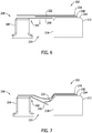
- FIG. 6 is a side view illustration of drape forming apparatus 202 including a flange forming device 238 in accordance with a third embodiment of the disclosure, in a first operating position
- FIG. 7 is a side view illustration of drape forming apparatus 202 including flange forming device 238 in a second operating position.
- flange forming device 238 includes the resistance device embodied as an elongated tray 240 coupled to standoff 204, in place of tray 206 and friction hinge 224 (shown in FIGS. 2 and 3 ).
- Elongated tray 240 includes a reinforced portion 242 defined at pivot line 208.
- elongated tray 240 is a single unitary structure, and deflects when the first force is induced against elongated tray 240.
- reinforced portion 242 provides the counteractive second force to elongated tray 240 to control the rate of rotation of elongated tray 240 without having any moving parts.
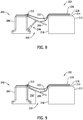
- Reinforced portion 242 may be fabricated from the same material as elongated tray 240, or may be fabricated from a different stiffer material. When fabricated from the same material, reinforced portion 242 may have an increased thickness to increase the stiffness thereof.
- FIG. 8 is a side view illustration of drape forming apparatus 202 including a flange forming device 244 in accordance with a fourth embodiment of the disclosure.
- flange forming device 244 includes the resistance device embodied as a linear actuator 246 extending between standoff 204 and tray 206.
- linear actuator 246 can be used as an alternative to friction hinge 224 of the embodiment shown in FIGS. 2 and 3 .
- Linear actuator 246 may be actuated by any suitable means such as, but not limited to, electrical and pneumatic. As such, the rate of rotation of tray 206 can be controlled using linear actuator 246 in a more regulated manner than conventional drape forming systems.
- FIG. 9 is a side view illustration of drape forming apparatus 202 including a flange forming device 248 in accordance with a fifth embodiment of the disclosure.
- flange forming device 248 includes the resistance device embodied as an inflatable bladder 250 positioned adjacent standoff 204 and tray 206.
- inflatable bladder 250 can be used as an alternative to friction hinge 224 of the embodiment shown in FIGS. 2 and 3 .
- Inflatable bladder 250 may be selectively filled with any suitable fluid, which enables inflatable bladder 250 to bias against tray 206 and provide the counteractive second force thereto.
- tray 206 deforms inflatable bladder 250 as tray 206 rotates about pivot line 208.
- the rate of rotation of tray 206 can be controlled using inflatable bladder 250 in a more regulated manner than conventional drape forming systems.
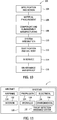
- Implementations of the disclosure may be described in the context of an aircraft manufacturing and service method 100 (shown in FIG. 10 ) and via an aircraft 102 (shown in FIG. 11 ).
- pre-production including specification and design 104 data of aircraft 102 may be used during the manufacturing process and other materials associated with the airframe may be procured 106.
- component and subassembly manufacturing 108 and system integration 110 of aircraft 102 occurs, prior to aircraft 102 entering its certification and delivery process 112.
- aircraft 102 may be placed in service 114.
- aircraft 102 is scheduled for periodic, routine, and scheduled maintenance and service 116, including any modification, reconfiguration, and/or refurbishment, for example.
- manufacturing and service method 100 may be implemented on platforms other than an aircraft.
- Each portion and process associated with aircraft manufacturing and/or service 100 may be performed or completed by a system integrator, a third party, and/or an operator (e.g., a customer).
- a system integrator may include without limitation any number of aircraft manufacturers and major-system subcontractors
- a third party may include without limitation any number of venders, subcontractors, and suppliers
- an operator may be an airline, leasing company, military entity, service organization, and so on.
- aircraft 102 produced via method 100 may include an airframe 118 having a plurality of systems 120 and an interior 122.
- high-level systems 120 include one or more of a propulsion system 124, an electrical system 126, a hydraulic system 128, an environmental system 130, and/or a threat detection/avoidance system 132.
- Threat detection/avoidance system 132 may be embodied as one or more sensors for detecting a threat received at aircraft 102, and a computing device for analyzing the threat and determining avoidance techniques for aircraft 102, as will be described in more detail below. Any number of other systems may be included.
- Apparatus and methods embodied herein may be employed during any one or more of the stages of method 100.
- components or subassemblies corresponding to component and subassembly production process 108 may be fabricated or manufactured in a manner similar to components or subassemblies produced while aircraft 102 is in service 114.
- one or more apparatus implementations, method implementations, or a combination thereof may be utilized during the production stages 108 and 110, for example, by substantially expediting assembly of, and/or reducing the cost of assembly of aircraft 102.
- apparatus implementations, method implementations, or a combination thereof may be utilized while aircraft 102 is being serviced or maintained, for example, during scheduled maintenance and service 116.
- aircraft may include, but is not limited to only including, airplanes, unmanned aerial vehicles (UAVs), gliders, helicopters, and/or any other object that travels through airspace.
- UAVs unmanned aerial vehicles
- helicopters helicopters
- any other object that travels through airspace may include, but is not limited to only including, airplanes, unmanned aerial vehicles (UAVs), gliders, helicopters, and/or any other object that travels through airspace.
- UAVs unmanned aerial vehicles
- helicopters helicopters, and/or any other object that travels through airspace.
- any other object that travels through airspace such as a maritime structure or an automotive structure.
- the method includes extending at least one layer 218 of composite material over upper forming surface 214 of forming tool 212, positioning flange portion 222 of at least one layer 218 of composite on tray 206 coplanarly aligned with upper forming surface 214 when tray 206 is in a first operating position, extending pressurized bladder 226 over forming tool 212 and tray 206, and inducing, with pressurized bladder 226, a first force against tray 206 such that tray 206 rotates about pivot line 208, and such that flange portion 222 is withdrawn from tray 206 and draped over at least one side forming surface 216 of forming tool 212.
- the method further includes positioning standoff 204 a distance from forming tool 212 such that gap 220 is defined therebetween, wherein tray 206 is coupled to standoff 204 and extends across gap 220 towards forming tool 212 when in the first operating position.
- the method also includes rotating tray 206 about hinge 210 coupled between standoff 204 and forming tool 212.
- the method includes coupling the resistance device to tray 206, and providing a second force, by the resistance device, to tray 206 to control a rate of rotation of tray 206.
- the second force opposes the first force.
- Inducing a first force includes inducing the first force of up to about 15 pounds per square inch (psi) against tray 206, and the resistance device is configured to provide the second force that is less than the first force.
- the resistance device can be embodied as a friction hinge 224 (shown in FIGS. 2 and 3 ), rotatable levers 232 (shown in FIGS. 4 and 5 ), reinforced portion 242 (shown in FIGS. 6 and 7 ), linear actuator 246 (shown in FIG. 8 ), or inflatable bladder 250 (shown in FIG. 9 ).
- inducing a first force includes forcing flange portion 222 against at least one side forming surface 216 as tray 206 rotates about pivot line 208.
- said flange forming device further comprises a standoff positioned a distance from said forming tool such that a gap is defined between said standoff and said forming tool, said tray coupled to said standoff and extending across the gap towards said forming tool when in the first operating position.
- said tray is coupled to said standoff via a hinge such that said tray rotates relative to said standoff.
- the apparatus further comprises a resistance device coupled to said tray, said resistance device configured to provide a second force that opposes the first force to control a rate of rotation of said tray.
- said pressurized bladder is configured to induce the first force of up to about 15 pounds per square inch (psi) (103 kilopascals (kPa)) against said tray, and said resistance device is configured to provide the second force that is less than the first force.
- psi pounds per square inch
- kPa kilopascals
- said resistance device comprises a friction hinge.
- said pressurized bladder is further configured to force the flange portion against said at least one side forming surface as said tray rotates about the pivot line.
- said tray is coupled to said standoff via a hinge.
- the first force of up to about 15 pounds per square inch (psi) (103 kilopascals (kPa)) is induced against said tray, and said resistance device configured to provide the second force that is less than the first force.
- said resistance device comprises a friction hinge.
- said resistance device comprises a reinforced portion of said tray defined at the pivot line, said reinforced portion configured to deflect when the first force is induced against said tray.
- said resistance device comprises a linear actuator extending between said standoff and said tray.
- said resistance device comprises an inflatable bladder positioned adjacent said standoff and said tray.
- the method further comprises positioning a standoff a distance from the forming tool such that a gap is defined therebetween, wherein the tray is coupled to the standoff and extends across the gap towards the forming tool when in the first operating position.
- the method further comprises rotating the tray about a hinge coupled between the standoff and the forming tool.
- the method further comprises: coupling a resistance device to the tray; and providing a second force, by the resistance device, to the tray to control a rate of rotation of the tray, the second force opposing the first force.
- inducing a first force comprises inducing the first force of up to about 15 pounds per square inch (psi) (103 kilopascals (kPa)) against the tray, the resistance device configured to provide the second force that is less than the first force.
- psi pounds per square inch
- kPa kilopascals
- inducing a first force comprises forcing the flange portion against the at least one side forming surface as the tray rotates about the pivot line.
Landscapes
- Engineering & Computer Science (AREA)
- Mechanical Engineering (AREA)
- Chemical & Material Sciences (AREA)
- Composite Materials (AREA)
- Casting Or Compression Moulding Of Plastics Or The Like (AREA)
- Moulding By Coating Moulds (AREA)
Abstract
Description
- The field of the present disclosure relates generally to composite structures and, more specifically, to systems and methods of hot drape forming composite structures.
- At least some known composite structures are formed using a process known as hot drape forming. Hot drape forming typically includes heating one or more plies of flat pre-impregnated (i.e., prepreg) composite material, and forcing the composite material around a mandrel with a vacuum bag or a pressurized bladder device. Composite structures, such as composite charges, are formed from one or more plies of composite material. Forcing the composite material around the mandrel facilitates forming composite parts for use in the aerospace industry, for example. More specifically, at least some known composite parts include a body portion and a flange portion that is formed when forced around the mandrel. However, uncontrolled compression of the composite material when forced around the mandrel can result in buckling or wrinkling of the plies within a composite part.
- In one aspect, a drape forming apparatus for use in forming a composite structure is provided. The apparatus includes a forming tool including an upper forming surface and at least one side forming surface that extends from the upper forming surface. The forming tool is configured to receive at least one layer of composite material extending over the upper forming surface. The apparatus also includes a flange forming device including a tray coplanarly aligned with the upper forming surface when in a first operating position. The tray is configured to receive a flange portion of the at least one layer of composite material. A pressurized bladder extends over the forming tool and the tray. The pressurized bladder is configured to induce a first force against the tray such that the tray rotates about a pivot line, and such that the flange portion is withdrawn from the tray and draped over the at least one side forming surface.
- In another aspect, a flange forming device for use in forming a composite structure from at least one layer of composite material is provided. The device includes a standoff, and a tray coupled to the standoff. The tray is rotatable about a pivot line defined between the tray and the standoff. The tray is configured to receive a flange portion of the at least one layer of composite material, and is configured to rotate when a first force is induced against the tray. The device also includes a resistance device coupled to the tray. The resistance device is configured to provide a second force that opposes the first force to control a rate of rotation of the tray.
- In yet another aspect, a method of forming a composite structure is provided. The method includes extending at least one layer of composite material over an upper forming surface of a forming tool, positioning a flange portion of the at least one layer of composite on a tray coplanarly aligned with the upper forming surface when the tray is in a first operating position, extending a pressurized bladder over the forming tool and the tray, and inducing, with the pressurized bladder, a first force against the tray such that the tray rotates about a pivot line, and such that the flange portion is withdrawn from the tray and draped over at least one side forming surface of the forming tool.
-
-
FIG. 1 is a perspective view of an exemplary flange forming device. -
FIG. 2 is a side view illustration of an exemplary drape forming apparatus including the flange forming device shown inFIG. 1 in a first operating position. -
FIG. 3 is a side view illustration of the drape forming apparatus shown inFIG. 2 including the flange forming device in a second operating position. -
FIG. 4 is a side view illustration of the drape forming apparatus including a flange forming device in accordance with a second embodiment of the disclosure, in a first operating position. -
FIG. 5 is a side view illustration of the drape forming apparatus shown inFIG. 4 including the flange forming device in a second operating position. -
FIG. 6 is a side view illustration of the drape forming apparatus including a flange forming device in accordance with a third embodiment of the disclosure, in a first operating position. -
FIG. 7 is a side view illustration of the drape forming apparatus shown inFIG. 8 including the flange forming device in a second operating position. -
FIG. 8 is a side view illustration of the drape forming apparatus including a flange forming device in accordance with a fourth embodiment of the disclosure. -
FIG. 9 is a side view illustration of the drape forming apparatus including a flange forming device in accordance with a fifth embodiment of the disclosure. -
FIG. 10 is a flow diagram of an exemplary aircraft production and service method. -
FIG. 11 is a block diagram of an exemplary aircraft. - The implementations described herein relate to systems and methods of forming a composite structure having a flange. More specifically, the systems and methods described herein include a flange forming device that, when used in combination with a pressurized bladder, facilitates controlling the pressure induced to at least one layer of composite material used to form the composite structure. For example, a flange portion of the layer of composite material is received on a tray of the flange forming device, and the pressurized bladder induces a force on the tray. The tray is rotatable about a pivot line such that the flange portion is progressively withdrawn from the tray and draped over a forming tool. The rate of rotation of the tray is controlled to ensure a more uniform and controlled pressure is induced to the flange portion when formed around the forming tool. As such, the systems and methods described herein facilitate forming composite structures in a more reliable, easier, and defect reducing manner.
-
FIG. 1 is a perspective view of an exemplaryflange forming device 200,FIG. 2 is a side view illustration of an exemplarydrape forming apparatus 202 includingflange forming device 200 shown inFIG. 1 in a first operating position, andFIG. 3 is a side view illustration ofdrape forming apparatus 202 includingflange forming device 200 in a second operating position. In the exemplary implementation,flange forming device 200 includes astandoff 204, and atray 206 coupled tostandoff 204. Tray 206 is rotatable about apivot line 208 defined betweentray 206 andstandoff 204, and rotates when a first force is induced againsttray 206. More specifically, as will be described in more detail below, a resistance device (not shown inFIG. 1 ) is coupled totray 206. The resistance device facilitates maintainingtray 206 in the first operating position by providing a counteractive second force to tray 206 greater than the force of gravity, andtray 206 only rotates when the first force is greater than the second force provided by the resistance device. As shown inFIG. 1 ,tray 206 is coupled tostandoff 204 via ahinge 210 such thattray 206 rotates relative tostandoff 204 aboutpivot line 208. In one implementation,hinge 210 is positioned alongpivot line 208. - Referring to
FIG. 2 ,drape forming apparatus 202 includesflange forming device 200 and a formingtool 212. Formingtool 212 includes an upper formingsurface 214 and at least oneside forming surface 216 that extends substantially perpendicularly from upper formingsurface 214. As will be described in more detail below, formingtool 212 receives at least onelayer 218 of composite material for forming a composite structure, having a flange, on formingtool 212 in-situ. In an alternative implementation,side forming surface 216 has any contour and extends from upper formingsurface 214 in any orientation that enablesdrape forming apparatus 202 to function as described herein. - In the exemplary implementation,
standoff 204 is positioned a distance from formingtool 212 such that agap 220 is defined therebetween. Tray 206 extends acrossgap 220 towards formingtool 212 whenflange forming device 200 is in the first operating position. More specifically,tray 206 is substantially coplanarly aligned with upper formingsurface 214 whenflange forming device 200 is in the first operating position. As such, when in the first operating position,tray 206 is positioned to receive aflange portion 222 of at least onelayer 218 of composite material. At least onelayer 218 is then heated, when embodied as prepreg, to facilitate softening the matrix material embedded therein. In one implementation, a heat blanket (not shown) covering at least onelayer 218 is used to soften the matrix material. Alternatively, heat lamps (not shown) may be used to heat the at least onelayer 218. - As described above,
flange forming device 200 includes a resistance device that facilitates maintainingtray 206 in the first operating position by providing a counteractive second force to tray 206 greater than the force of gravity. In one implementation, the resistance device is embodied as afriction hinge 224 coupled betweenstandoff 204 andtray 206. Friction hinges, also known as torque hinges, provide torque between rotatable components thereof about a common axis. As such,friction hinge 224 provides the second force capable of maintainingtray 206 in the first operating position. -
Drape forming apparatus 202 also includes apressurized bladder 226 that extends over formingtool 212 andtray 206. In the exemplary implementation,pressurized bladder 226 is fabricated from an elastically deformable material, and is pressurized to induce the first force againsttray 206 such thattray 206 rotates aboutpivot line 208. More specifically,pressurized bladder 226 induces the first force of up to about 15 pounds per square inch (psi) (about 103 kilopascals (kPa)) againsttray 206. The resistance device provides the counteractive second force that is less than the first force induced bypressurized bladder 226. As such, the rate of rotation oftray 206 is controlled to reduce the formation of wrinkles withinflange portion 222. - Referring to
FIG. 2 , the first force induced bypressurized bladder 226 is greater than the second force provided byfriction hinge 224. As such,pressurized bladder 226forces tray 206 from the first operating position towards the second operating position. Moreover,flange portion 222 is withdrawn fromtray 206 and draped overside forming surface 216 astray 206 rotates aboutpivot line 208. More specifically,pressurized bladder 226 progressively coversflange portion 222 asflange portion 222 is withdrawn fromtray 206. As such, pressure is gradually applied toflange portion 222 to facilitate reducing wrinkle formation therein.Pressurized bladder 226 then biases at least onelayer 218 against upper formingsurface 214 andside forming surface 216 to form the composite structure. As such,pressurized bladder 226 applies a substantially uniform pressure across at least onelayer 218 and holds at least onelayer 218 in place on formingtool 212 as the temperature of the at least onelayer 218 is reduced, thereby forming the composite structure. In an alternative implementation, a slip film (not shown) or any other suitable friction reducing device may be positioned betweentray 206 andflange portion 222 to facilitate reducing the formation of wrinkles inflange portion 222. -
FIG. 4 is a side view illustration ofdrape forming apparatus 202 including aflange forming device 228 in accordance with a second embodiment of the disclosure, in a first operating position, andFIG. 5 is a side view illustration ofdrape forming apparatus 202 includingflange forming device 228 in a second operating position. In the exemplary implementation ofFIGS. 4 and 5 ,flange forming device 228 includes the resistance device embodied as a retractable hingedtray 230 coupled tostandoff 204, in place oftray 206 and friction hinge 224 (shown inFIGS. 2 and 3 ). Retractable hingedtray 230 is coupled tostandoff 204 viarotatable levers 232. Retractable hingedtray 230 is rotatable about afirst pivot line 234 and asecond pivot line 236 defined betweenrotatable levers 232 and retractable hingedtray 230, androtatable levers 232 are rotatable about pivot lines (not shown) defined betweenrotatable levers 232 andstandoff 204, thereby defining a range of motion for retractable hingedtray 230 to be fully retractable withinstandoff 204. As such, the range of motion facilitates reducing friction between at least onelayer 218 of composite material and retractable hingedtray 230 as at least onelayer 218 is withdrawn therefrom, and facilitates reducing the likelihood ofpressurized bladder 226 from becoming caught betweenstandoff 204 and retractable hingedtray 230. -
FIG. 6 is a side view illustration ofdrape forming apparatus 202 including aflange forming device 238 in accordance with a third embodiment of the disclosure, in a first operating position, andFIG. 7 is a side view illustration ofdrape forming apparatus 202 includingflange forming device 238 in a second operating position. In the exemplary implementation ofFIGS. 6 and 7 ,flange forming device 238 includes the resistance device embodied as anelongated tray 240 coupled tostandoff 204, in place oftray 206 and friction hinge 224 (shown inFIGS. 2 and 3 ).Elongated tray 240 includes a reinforcedportion 242 defined atpivot line 208. More specifically,elongated tray 240 is a single unitary structure, and deflects when the first force is induced againstelongated tray 240. As such, reinforcedportion 242 provides the counteractive second force toelongated tray 240 to control the rate of rotation ofelongated tray 240 without having any moving parts. Reinforcedportion 242 may be fabricated from the same material aselongated tray 240, or may be fabricated from a different stiffer material. When fabricated from the same material, reinforcedportion 242 may have an increased thickness to increase the stiffness thereof. -
FIG. 8 is a side view illustration ofdrape forming apparatus 202 including aflange forming device 244 in accordance with a fourth embodiment of the disclosure. In the exemplary implementation,flange forming device 244 includes the resistance device embodied as alinear actuator 246 extending betweenstandoff 204 andtray 206. For example,linear actuator 246 can be used as an alternative to friction hinge 224 of the embodiment shown inFIGS. 2 and 3 .Linear actuator 246 may be actuated by any suitable means such as, but not limited to, electrical and pneumatic. As such, the rate of rotation oftray 206 can be controlled usinglinear actuator 246 in a more regulated manner than conventional drape forming systems. -
FIG. 9 is a side view illustration ofdrape forming apparatus 202 including aflange forming device 248 in accordance with a fifth embodiment of the disclosure. In the exemplary implementation,flange forming device 248 includes the resistance device embodied as aninflatable bladder 250 positionedadjacent standoff 204 andtray 206. For example,inflatable bladder 250 can be used as an alternative to friction hinge 224 of the embodiment shown inFIGS. 2 and 3 .Inflatable bladder 250 may be selectively filled with any suitable fluid, which enablesinflatable bladder 250 to bias againsttray 206 and provide the counteractive second force thereto. As pressure is applied bypressurized bladder 226,tray 206 deformsinflatable bladder 250 astray 206 rotates aboutpivot line 208. As such, the rate of rotation oftray 206 can be controlled usinginflatable bladder 250 in a more regulated manner than conventional drape forming systems. - Implementations of the disclosure may be described in the context of an aircraft manufacturing and service method 100 (shown in
FIG. 10 ) and via an aircraft 102 (shown inFIG. 11 ). During pre-production, including specification anddesign 104 data of aircraft 102 may be used during the manufacturing process and other materials associated with the airframe may be procured 106. During production, component andsubassembly manufacturing 108 andsystem integration 110 of aircraft 102 occurs, prior to aircraft 102 entering its certification anddelivery process 112. Upon successful satisfaction and completion of airframe certification, aircraft 102 may be placed inservice 114. While in service by a customer, aircraft 102 is scheduled for periodic, routine, and scheduled maintenance andservice 116, including any modification, reconfiguration, and/or refurbishment, for example. In alternative implementations, manufacturing andservice method 100 may be implemented on platforms other than an aircraft. - Each portion and process associated with aircraft manufacturing and/or
service 100 may be performed or completed by a system integrator, a third party, and/or an operator (e.g., a customer). For the purposes of this description, a system integrator may include without limitation any number of aircraft manufacturers and major-system subcontractors; a third party may include without limitation any number of venders, subcontractors, and suppliers; and an operator may be an airline, leasing company, military entity, service organization, and so on. - As shown in
FIG. 11 , aircraft 102 produced viamethod 100 may include anairframe 118 having a plurality ofsystems 120 and an interior 122. Examples of high-level systems 120 include one or more of apropulsion system 124, anelectrical system 126, ahydraulic system 128, anenvironmental system 130, and/or a threat detection/avoidance system 132. Threat detection/avoidance system 132 may be embodied as one or more sensors for detecting a threat received at aircraft 102, and a computing device for analyzing the threat and determining avoidance techniques for aircraft 102, as will be described in more detail below. Any number of other systems may be included. - Apparatus and methods embodied herein may be employed during any one or more of the stages of
method 100. For example, components or subassemblies corresponding to component andsubassembly production process 108 may be fabricated or manufactured in a manner similar to components or subassemblies produced while aircraft 102 is inservice 114. Also, one or more apparatus implementations, method implementations, or a combination thereof may be utilized during the production stages 108 and 110, for example, by substantially expediting assembly of, and/or reducing the cost of assembly of aircraft 102. Similarly, one or more of apparatus implementations, method implementations, or a combination thereof may be utilized while aircraft 102 is being serviced or maintained, for example, during scheduled maintenance andservice 116. - As used herein, the term "aircraft" may include, but is not limited to only including, airplanes, unmanned aerial vehicles (UAVs), gliders, helicopters, and/or any other object that travels through airspace. Moreover, it should be understood that, although an aerospace example is shown, the principles of the disclosure may be applied to other structures, such as a maritime structure or an automotive structure.
- A method of forming a composite structure is also described herein. Referring to
FIGS. 2 and 3 , the method includes extending at least onelayer 218 of composite material over upper formingsurface 214 of formingtool 212,positioning flange portion 222 of at least onelayer 218 of composite ontray 206 coplanarly aligned with upper formingsurface 214 whentray 206 is in a first operating position, extendingpressurized bladder 226 over formingtool 212 andtray 206, and inducing, withpressurized bladder 226, a first force againsttray 206 such thattray 206 rotates aboutpivot line 208, and such thatflange portion 222 is withdrawn fromtray 206 and draped over at least oneside forming surface 216 of formingtool 212. - In one implementation, the method further includes positioning standoff 204 a distance from forming
tool 212 such thatgap 220 is defined therebetween, whereintray 206 is coupled tostandoff 204 and extends acrossgap 220 towards formingtool 212 when in the first operating position. The method also includesrotating tray 206 abouthinge 210 coupled betweenstandoff 204 and formingtool 212. - In one implementation, the method includes coupling the resistance device to
tray 206, and providing a second force, by the resistance device, totray 206 to control a rate of rotation oftray 206. The second force opposes the first force. Inducing a first force includes inducing the first force of up to about 15 pounds per square inch (psi) againsttray 206, and the resistance device is configured to provide the second force that is less than the first force. The resistance device can be embodied as a friction hinge 224 (shown inFIGS. 2 and 3 ), rotatable levers 232 (shown inFIGS. 4 and 5 ), reinforced portion 242 (shown inFIGS. 6 and 7 ), linear actuator 246 (shown inFIG. 8 ), or inflatable bladder 250 (shown inFIG. 9 ). Moreover, inducing a first force includes forcingflange portion 222 against at least oneside forming surface 216 astray 206 rotates aboutpivot line 208. - According to a first aspect of the disclosure, there is provided:
- A drape forming apparatus for use in forming a composite structure, said apparatus comprising: a forming tool comprising an upper forming surface and at least one side forming surface that extends from said upper forming surface, said forming tool configured to receive at least one layer of composite material extending over said upper forming surface; a flange forming device comprising a tray coplanarly aligned with said upper forming surface when in a first operating position, said tray configured to receive a flange portion of the at least one layer of composite material; and a pressurized bladder configured to extend over said forming tool and said tray, said pressurized bladder configured to induce a first force against said tray such that said tray rotates about a pivot line, and such that the flange portion is withdrawn from said tray and draped over said at least one side forming surface.
- Optionally, said flange forming device further comprises a standoff positioned a distance from said forming tool such that a gap is defined between said standoff and said forming tool, said tray coupled to said standoff and extending across the gap towards said forming tool when in the first operating position.
- Optionally, said tray is coupled to said standoff via a hinge such that said tray rotates relative to said standoff.
- Optionally, the apparatus further comprises a resistance device coupled to said tray, said resistance device configured to provide a second force that opposes the first force to control a rate of rotation of said tray.
- Optionally, said pressurized bladder is configured to induce the first force of up to about 15 pounds per square inch (psi) (103 kilopascals (kPa)) against said tray, and said resistance device is configured to provide the second force that is less than the first force.
- Optionally, said resistance device comprises a friction hinge.
- Optionally, said pressurized bladder is further configured to force the flange portion against said at least one side forming surface as said tray rotates about the pivot line.
- According to a second aspect of the disclosure, there is provided:
- A flange forming device for use in forming a composite structure from at least one layer of composite material, said device comprising: a standoff; a tray coupled to said standoff, said tray rotatable about a pivot line defined between said tray and said standoff, wherein said tray is configured to receive a flange portion of the at least one layer of composite material, and is configured to rotate when a first force is induced against said tray; and a resistance device coupled to said tray, said resistance device configured to provide a second force that opposes the first force to control a rate of rotation of said tray.
- Optionally, said tray is coupled to said standoff via a hinge.
- Optionally, the first force of up to about 15 pounds per square inch (psi) (103 kilopascals (kPa)) is induced against said tray, and said resistance device configured to provide the second force that is less than the first force.
- Optionally, said resistance device comprises a friction hinge.
- Optionally, said resistance device comprises a reinforced portion of said tray defined at the pivot line, said reinforced portion configured to deflect when the first force is induced against said tray.
- Optionally, said resistance device comprises a linear actuator extending between said standoff and said tray.
- Optionally, said resistance device comprises an inflatable bladder positioned adjacent said standoff and said tray.
- According to a third aspect of the disclosure, there is provided:
- A method of forming a composite structure, said method comprising:
- extending at least one layer of composite material over an upper forming surface of a forming tool; positioning a flange portion of the at least one layer of composite material on a tray coplanarly aligned with the upper forming surface when the tray is in a first operating position; extending a pressurized bladder over the forming tool and the tray; and inducing, with the pressurized bladder, a first force against the tray such that the tray rotates about a pivot line, and such that the flange portion is withdrawn from the tray and draped over at least one side forming surface of the forming tool.
- Optionally, the method further comprises positioning a standoff a distance from the forming tool such that a gap is defined therebetween, wherein the tray is coupled to the standoff and extends across the gap towards the forming tool when in the first operating position.
- Optionally, the method further comprises rotating the tray about a hinge coupled between the standoff and the forming tool.
- Optionally, the method further comprises: coupling a resistance device to the tray; and providing a second force, by the resistance device, to the tray to control a rate of rotation of the tray, the second force opposing the first force.
- Optionally, inducing a first force comprises inducing the first force of up to about 15 pounds per square inch (psi) (103 kilopascals (kPa)) against the tray, the resistance device configured to provide the second force that is less than the first force.
- Optionally, inducing a first force comprises forcing the flange portion against the at least one side forming surface as the tray rotates about the pivot line.
- This written description uses examples to disclose various implementations, including the best mode, and also to enable any person skilled in the art to practice the various implementations, including making and using any devices or systems and performing any incorporated methods. The patentable scope of the disclosure is defined by the claims, and may include other examples that occur to those skilled in the art. Such other examples are intended to be within the scope of the claims if they have structural elements that do not differ from the literal language of the claims, or if they include equivalent structural elements with insubstantial differences from the literal language of the claims.
Claims (15)
- A drape forming apparatus (202) for use in forming a composite structure, said apparatus comprising:a forming tool (212) comprising an upper forming surface (214) and at least one side forming surface (216) that extends from said upper forming surface, said forming tool configured to receive at least one layer (218) of composite material extending over said upper forming surface;a flange forming device (200, 228, 238, 244, 248) comprising a tray (206, 230, 240) coplanarly aligned with said upper forming surface when in a first operating position, said tray configured to receive a flange portion (222) of the at least one layer of composite material; anda pressurized bladder (226) configured to extend over said forming tool and said tray, said pressurized bladder configured to induce a first force against said tray such that said tray rotates about a pivot line (208), and such that the flange portion is withdrawn from said tray and draped over said at least one side forming surface.
- The apparatus (202) in accordance with Claim 1, wherein said flange forming device (200) further comprises a standoff (204) positioned a distance from said forming tool (212) such that a gap (220) is defined between said standoff and said forming tool, said tray (206) coupled to said standoff and extending across the gap towards said forming tool when in the first operating position.
- The apparatus (202) in accordance with Claim 2, wherein said tray (206) is coupled to said standoff (204) via a hinge (210) such that said tray rotates relative to said standoff.
- The apparatus (202) in accordance with any one of Claims 1 to 3, wherein said pressurized bladder (226) is further configured to force the flange portion (222) against said at least one side forming surface (216) as said tray (206) rotates about the pivot line (208).
- The apparatus (202) in accordance with any one of Claims 1 to 4 further comprising a resistance device coupled to said tray (206), said resistance device configured to provide a second force that opposes the first force to control a rate of rotation of said tray.
- The apparatus (202) in accordance with Claim 5, wherein said pressurized bladder (226) is configured to induce the first force of up to about 103 kilopascals (kPa) against said tray (206), and said resistance device is configured to provide the second force that is less than the first force.
- The apparatus (202) in accordance with Claim 5 or 6, wherein said resistance device comprises a friction hinge (224).
- The apparatus (202) in accordance with Claim 5 or 6, wherein said resistance device comprises a reinforced portion (242) of said tray (240) defined at the pivot line (208), said reinforced portion configured to deflect when the first force is induced against said tray.
- The apparatus (202) in accordance with Claim 5 or 6, wherein said resistance device comprises a linear actuator (246) extending between said standoff (204) and said tray (206).
- The apparatus (202) in accordance with Claim 5 or 6, wherein said resistance device comprises an inflatable bladder (250) positioned adjacent said standoff (204) and said tray (206).
- A method of forming a composite structure, said method comprising:extending at least one layer (218) of composite material over an upper forming surface (214) of a forming tool (212);positioning a flange portion (222) of the at least one layer of composite material on a tray (206, 230, 240) coplanarly aligned with the upper forming surface when the tray is in a first operating position;extending a pressurized bladder (226) over the forming tool and the tray; andinducing, with the pressurized bladder, a first force against the tray such that the tray rotates about a pivot line (208), and such that the flange portion is withdrawn from the tray and draped over at least one side forming surface (216) of the forming tool.
- The method in accordance with Claim 11 further comprising positioning a standoff (204) a distance from the forming tool (212) such that a gap (220) is defined therebetween, wherein the tray (206) is coupled to the standoff and extends across the gap towards the forming tool when in the first operating position.
- The method in accordance with Claim 12 further comprising rotating the tray (206) about a hinge (210) coupled between the standoff (204) and the forming tool (212).
- The method in accordance with any one of Claims 11 to 13 further comprising:coupling a resistance device to the tray (206); andproviding a second force, by the resistance device, to the tray to control a rate of rotation of the tray, the second force opposing the first force.
- The method in accordance with any one of Claims 11 to 14, wherein inducing a first force comprises forcing the flange portion (222) against the at least one side forming surface (216) as the tray (206) rotates about the pivot line (208).
Applications Claiming Priority (1)
| Application Number | Priority Date | Filing Date | Title |
|---|---|---|---|
| US15/004,622 US10688697B2 (en) | 2016-01-22 | 2016-01-22 | Apparatus and method of forming a composite structure |
Publications (2)
| Publication Number | Publication Date |
|---|---|
| EP3196006A1 true EP3196006A1 (en) | 2017-07-26 |
| EP3196006B1 EP3196006B1 (en) | 2021-01-06 |
Family
ID=57391912
Family Applications (1)
| Application Number | Title | Priority Date | Filing Date |
|---|---|---|---|
| EP16200344.6A Active EP3196006B1 (en) | 2016-01-22 | 2016-11-23 | Apparatus and method of forming a composite structure |
Country Status (2)
| Country | Link |
|---|---|
| US (1) | US10688697B2 (en) |
| EP (1) | EP3196006B1 (en) |
Cited By (1)
| Publication number | Priority date | Publication date | Assignee | Title |
|---|---|---|---|---|
| IT202000028046A1 (en) * | 2020-11-23 | 2022-05-23 | Leonardo Spa | METHOD AND DEVICE FOR THE MANUFACTURING OF A STRUCTURAL ELEMENT IN COMPOSITE MATERIAL WITH A Z-PROFILE |
Families Citing this family (11)
| Publication number | Priority date | Publication date | Assignee | Title |
|---|---|---|---|---|
| US10913198B2 (en) * | 2017-10-19 | 2021-02-09 | The Boeing Company | Pyrometer control for hot drape formers |
| US11826970B2 (en) | 2020-12-07 | 2023-11-28 | The Boeing Company | Forming apparatus, method, and system |
| US11685128B2 (en) | 2020-12-07 | 2023-06-27 | The Boeing Company | System and method for fabricating a composite structure |
| US12194693B2 (en) | 2020-12-07 | 2025-01-14 | The Boeing Company | Forming apparatus, method, and system |
| US11654641B2 (en) | 2020-12-07 | 2023-05-23 | The Boeing Company | Composite ply placement system and method |
| US12138868B2 (en) * | 2021-01-04 | 2024-11-12 | The Boeing Company | Drape forming apparatus and device, and method of forming a composite structure |
| JP7225320B2 (en) | 2021-06-28 | 2023-02-20 | 三菱重工業株式会社 | Shaping method and shaping apparatus |
| US12103249B2 (en) | 2021-08-30 | 2024-10-01 | The Boeing Company | Composite forming apparatus, methods, and systems |
| US11999116B2 (en) | 2021-08-30 | 2024-06-04 | The Boeing Company | Composite forming apparatus, system and method |
| US11897209B2 (en) | 2021-08-30 | 2024-02-13 | The Boeing Company | Composite forming apparatus, system and method |
| US12138864B2 (en) | 2021-08-30 | 2024-11-12 | The Boeing Company | Forming apparatus, methods, and systems |
Citations (4)
| Publication number | Priority date | Publication date | Assignee | Title |
|---|---|---|---|---|
| EP2047972A1 (en) * | 2007-10-09 | 2009-04-15 | Saab Ab | Method and device for shaping of composite material |
| EP2116358A1 (en) * | 2008-05-09 | 2009-11-11 | Saab Ab | Method and apparatus for conforming a blank |
| JP2010115867A (en) * | 2008-11-13 | 2010-05-27 | Fuji Heavy Ind Ltd | Folding molding apparatus |
| EP2954994A1 (en) * | 2014-06-04 | 2015-12-16 | The Boeing Company | Systems and methods for defining a surface contour of a layered charge of material |
Family Cites Families (14)
| Publication number | Priority date | Publication date | Assignee | Title |
|---|---|---|---|---|
| US2594262A (en) * | 1950-03-02 | 1952-04-22 | Howe Folding Furniture Inc | Drop leaf support construction for a table or the like |
| US4844398A (en) * | 1988-06-10 | 1989-07-04 | B. Walter & Co., Inc. | Drop leaf support with safety ring and cover |
| JP2765981B2 (en) * | 1989-08-28 | 1998-06-18 | 富士重工業株式会社 | Method and apparatus for bending composite material |
| US5549051A (en) * | 1995-02-06 | 1996-08-27 | Zimmerman; Harvey | Three piece hinge type drop-leaf support |
| US6814916B2 (en) | 2002-08-30 | 2004-11-09 | The Boeing Company | Forming method for composites |
| US7118370B2 (en) | 2002-08-30 | 2006-10-10 | The Boeing Company | Composite spar drape forming machine |
| JP2006312260A (en) * | 2005-05-09 | 2006-11-16 | Fuji Heavy Ind Ltd | Pre-preg bending apparatus and bending method thereof |
| DE102007058727A1 (en) * | 2007-12-06 | 2009-06-10 | Airbus Deutschland Gmbh | A method of making a FVW preform from a laminate having at least two prepreg layers and a manufacturing apparatus for such a method |
| US20100050388A1 (en) * | 2008-09-04 | 2010-03-04 | Mcneilus Truck And Manufacturing, Inc. | Molded Hinge Article for a Side-Loading Refuse Vehicle and Method of Making |
| US8556618B2 (en) * | 2011-04-07 | 2013-10-15 | Spirit Aerosystems, Inc. | Method and bladder apparatus for forming composite parts |
| JP2014051065A (en) * | 2012-09-10 | 2014-03-20 | Mitsubishi Heavy Ind Ltd | Molding apparatus and molding method of prepreg laminated material |
| US9637059B2 (en) * | 2015-01-19 | 2017-05-02 | Ford Global Technologies, Llc | Integrated sliding armrest and hinge assembly subsystem for a console assembly |
| JP6537921B2 (en) * | 2015-08-06 | 2019-07-03 | 三菱重工業株式会社 | Apparatus for producing fiber-reinforced plastic, movable base, method for producing shaped fiber substrate, and method for producing fiber-reinforced plastic |
| US10213968B2 (en) * | 2016-03-04 | 2019-02-26 | The Boeing Company | Dynamic forming tools for composite parts |
-
2016
- 2016-01-22 US US15/004,622 patent/US10688697B2/en active Active
- 2016-11-23 EP EP16200344.6A patent/EP3196006B1/en active Active
Patent Citations (4)
| Publication number | Priority date | Publication date | Assignee | Title |
|---|---|---|---|---|
| EP2047972A1 (en) * | 2007-10-09 | 2009-04-15 | Saab Ab | Method and device for shaping of composite material |
| EP2116358A1 (en) * | 2008-05-09 | 2009-11-11 | Saab Ab | Method and apparatus for conforming a blank |
| JP2010115867A (en) * | 2008-11-13 | 2010-05-27 | Fuji Heavy Ind Ltd | Folding molding apparatus |
| EP2954994A1 (en) * | 2014-06-04 | 2015-12-16 | The Boeing Company | Systems and methods for defining a surface contour of a layered charge of material |
Cited By (3)
| Publication number | Priority date | Publication date | Assignee | Title |
|---|---|---|---|---|
| IT202000028046A1 (en) * | 2020-11-23 | 2022-05-23 | Leonardo Spa | METHOD AND DEVICE FOR THE MANUFACTURING OF A STRUCTURAL ELEMENT IN COMPOSITE MATERIAL WITH A Z-PROFILE |
| WO2022107109A1 (en) * | 2020-11-23 | 2022-05-27 | Leonardo S.P.A. | Method and device for manufacturing a structural element in composite material with a z-shaped profile |
| US12559255B2 (en) | 2020-11-23 | 2026-02-24 | Leonardo S.P.A. | Method and device for manufacturing a structural element in composite material with a Z-shaped profile |
Also Published As
| Publication number | Publication date |
|---|---|
| EP3196006B1 (en) | 2021-01-06 |
| US20170210040A1 (en) | 2017-07-27 |
| US10688697B2 (en) | 2020-06-23 |
Similar Documents
| Publication | Publication Date | Title |
|---|---|---|
| EP3196006B1 (en) | Apparatus and method of forming a composite structure | |
| US9914268B2 (en) | Systems and methods for defining a surface contour of a layered charge of material | |
| ES2805138T3 (en) | Method to minimize inconsistencies that appear on the surface of a composite component and a precured composite strip | |
| US9211679B1 (en) | Systems and methods of forming a skin for a composite structure and composite structures including the same | |
| US20190329508A1 (en) | Method And Apparatus Of Modular Punch Forming Plates For Alignment Of A Stringer For A Vehicle | |
| US9144959B1 (en) | Methods for assembling a skin of a composite structure | |
| US10751955B2 (en) | Unitized composite structure manufacturing system | |
| US20160121589A1 (en) | Method and system of forming a composite laminate | |
| GB2567951B (en) | Apparatus and method of forming a composite structure | |
| US9511548B1 (en) | Systems and methods for assembling a skin of a composite structure | |
| US20160059443A1 (en) | Method and system of forming a releasable support and method of pre-cure removal of a composite laminate | |
| US10173371B1 (en) | System and method for forming a bonded joint | |
| EP3546200B1 (en) | Methods for forming bonded structures | |
| EP4353456B1 (en) | Systems and methods for removing a backing from a ply of composite material | |
| US10882262B2 (en) | Flexible mandrel for forming composite structures | |
| US9545758B2 (en) | Two piece mandrel manufacturing system | |
| US20170081015A1 (en) | Wing structure, stringer structure, and related apparatus and methods of assembly | |
| US8029644B2 (en) | Controlled temperature scrap removal for tape process | |
| US11155047B2 (en) | Caul body and a method for forming a composite structure | |
| US12605908B2 (en) | Systems and methods for forming composite workpieces | |
| US12179440B2 (en) | Systems and methods for shaping composite structures | |
| CN120056574A (en) | System and method for compacting ceramic composite materials |
Legal Events
| Date | Code | Title | Description |
|---|---|---|---|
| PUAI | Public reference made under article 153(3) epc to a published international application that has entered the european phase |
Free format text: ORIGINAL CODE: 0009012 |
|
| STAA | Information on the status of an ep patent application or granted ep patent |
Free format text: STATUS: REQUEST FOR EXAMINATION WAS MADE |
|
| 17P | Request for examination filed |
Effective date: 20161123 |
|
| AK | Designated contracting states |
Kind code of ref document: A1 Designated state(s): AL AT BE BG CH CY CZ DE DK EE ES FI FR GB GR HR HU IE IS IT LI LT LU LV MC MK MT NL NO PL PT RO RS SE SI SK SM TR |
|
| AX | Request for extension of the european patent |
Extension state: BA ME |
|
| STAA | Information on the status of an ep patent application or granted ep patent |
Free format text: STATUS: EXAMINATION IS IN PROGRESS |
|
| 17Q | First examination report despatched |
Effective date: 20190531 |
|
| REG | Reference to a national code |
Ref country code: DE Ref legal event code: R079 Ref document number: 602016050934 Country of ref document: DE Free format text: PREVIOUS MAIN CLASS: B29C0070440000 Ipc: B29C0053820000 |
|
| GRAP | Despatch of communication of intention to grant a patent |
Free format text: ORIGINAL CODE: EPIDOSNIGR1 |
|
| STAA | Information on the status of an ep patent application or granted ep patent |
Free format text: STATUS: GRANT OF PATENT IS INTENDED |
|
| RIC1 | Information provided on ipc code assigned before grant |
Ipc: B29C 53/02 20060101ALI20200605BHEP Ipc: B29C 70/54 20060101ALI20200605BHEP Ipc: B29C 43/36 20060101ALI20200605BHEP Ipc: B29C 53/82 20060101AFI20200605BHEP Ipc: B29C 70/44 20060101ALI20200605BHEP Ipc: B29C 43/12 20060101ALI20200605BHEP |
|
| INTG | Intention to grant announced |
Effective date: 20200624 |
|
| GRAS | Grant fee paid |
Free format text: ORIGINAL CODE: EPIDOSNIGR3 |
|
| GRAA | (expected) grant |
Free format text: ORIGINAL CODE: 0009210 |
|
| STAA | Information on the status of an ep patent application or granted ep patent |
Free format text: STATUS: THE PATENT HAS BEEN GRANTED |
|
| AK | Designated contracting states |
Kind code of ref document: B1 Designated state(s): AL AT BE BG CH CY CZ DE DK EE ES FI FR GB GR HR HU IE IS IT LI LT LU LV MC MK MT NL NO PL PT RO RS SE SI SK SM TR |
|
| REG | Reference to a national code |
Ref country code: GB Ref legal event code: FG4D |
|
| REG | Reference to a national code |
Ref country code: AT Ref legal event code: REF Ref document number: 1351896 Country of ref document: AT Kind code of ref document: T Effective date: 20210115 Ref country code: CH Ref legal event code: EP |
|
| REG | Reference to a national code |
Ref country code: DE Ref legal event code: R096 Ref document number: 602016050934 Country of ref document: DE |
|
| REG | Reference to a national code |
Ref country code: IE Ref legal event code: FG4D |
|
| REG | Reference to a national code |
Ref country code: NL Ref legal event code: MP Effective date: 20210106 |
|
| REG | Reference to a national code |
Ref country code: AT Ref legal event code: MK05 Ref document number: 1351896 Country of ref document: AT Kind code of ref document: T Effective date: 20210106 |
|
| REG | Reference to a national code |
Ref country code: LT Ref legal event code: MG9D |
|
| PG25 | Lapsed in a contracting state [announced via postgrant information from national office to epo] |
Ref country code: NO Free format text: LAPSE BECAUSE OF FAILURE TO SUBMIT A TRANSLATION OF THE DESCRIPTION OR TO PAY THE FEE WITHIN THE PRESCRIBED TIME-LIMIT Effective date: 20210406 Ref country code: PT Free format text: LAPSE BECAUSE OF FAILURE TO SUBMIT A TRANSLATION OF THE DESCRIPTION OR TO PAY THE FEE WITHIN THE PRESCRIBED TIME-LIMIT Effective date: 20210506 Ref country code: FI Free format text: LAPSE BECAUSE OF FAILURE TO SUBMIT A TRANSLATION OF THE DESCRIPTION OR TO PAY THE FEE WITHIN THE PRESCRIBED TIME-LIMIT Effective date: 20210106 Ref country code: GR Free format text: LAPSE BECAUSE OF FAILURE TO SUBMIT A TRANSLATION OF THE DESCRIPTION OR TO PAY THE FEE WITHIN THE PRESCRIBED TIME-LIMIT Effective date: 20210407 Ref country code: HR Free format text: LAPSE BECAUSE OF FAILURE TO SUBMIT A TRANSLATION OF THE DESCRIPTION OR TO PAY THE FEE WITHIN THE PRESCRIBED TIME-LIMIT Effective date: 20210106 Ref country code: NL Free format text: LAPSE BECAUSE OF FAILURE TO SUBMIT A TRANSLATION OF THE DESCRIPTION OR TO PAY THE FEE WITHIN THE PRESCRIBED TIME-LIMIT Effective date: 20210106 Ref country code: BG Free format text: LAPSE BECAUSE OF FAILURE TO SUBMIT A TRANSLATION OF THE DESCRIPTION OR TO PAY THE FEE WITHIN THE PRESCRIBED TIME-LIMIT Effective date: 20210406 Ref country code: LT Free format text: LAPSE BECAUSE OF FAILURE TO SUBMIT A TRANSLATION OF THE DESCRIPTION OR TO PAY THE FEE WITHIN THE PRESCRIBED TIME-LIMIT Effective date: 20210106 |
|
| PG25 | Lapsed in a contracting state [announced via postgrant information from national office to epo] |
Ref country code: SE Free format text: LAPSE BECAUSE OF FAILURE TO SUBMIT A TRANSLATION OF THE DESCRIPTION OR TO PAY THE FEE WITHIN THE PRESCRIBED TIME-LIMIT Effective date: 20210106 Ref country code: LV Free format text: LAPSE BECAUSE OF FAILURE TO SUBMIT A TRANSLATION OF THE DESCRIPTION OR TO PAY THE FEE WITHIN THE PRESCRIBED TIME-LIMIT Effective date: 20210106 Ref country code: RS Free format text: LAPSE BECAUSE OF FAILURE TO SUBMIT A TRANSLATION OF THE DESCRIPTION OR TO PAY THE FEE WITHIN THE PRESCRIBED TIME-LIMIT Effective date: 20210106 Ref country code: PL Free format text: LAPSE BECAUSE OF FAILURE TO SUBMIT A TRANSLATION OF THE DESCRIPTION OR TO PAY THE FEE WITHIN THE PRESCRIBED TIME-LIMIT Effective date: 20210106 Ref country code: AT Free format text: LAPSE BECAUSE OF FAILURE TO SUBMIT A TRANSLATION OF THE DESCRIPTION OR TO PAY THE FEE WITHIN THE PRESCRIBED TIME-LIMIT Effective date: 20210106 |
|
| PG25 | Lapsed in a contracting state [announced via postgrant information from national office to epo] |
Ref country code: IS Free format text: LAPSE BECAUSE OF FAILURE TO SUBMIT A TRANSLATION OF THE DESCRIPTION OR TO PAY THE FEE WITHIN THE PRESCRIBED TIME-LIMIT Effective date: 20210506 |
|
| REG | Reference to a national code |
Ref country code: DE Ref legal event code: R097 Ref document number: 602016050934 Country of ref document: DE |
|
| PG25 | Lapsed in a contracting state [announced via postgrant information from national office to epo] |
Ref country code: CZ Free format text: LAPSE BECAUSE OF FAILURE TO SUBMIT A TRANSLATION OF THE DESCRIPTION OR TO PAY THE FEE WITHIN THE PRESCRIBED TIME-LIMIT Effective date: 20210106 Ref country code: EE Free format text: LAPSE BECAUSE OF FAILURE TO SUBMIT A TRANSLATION OF THE DESCRIPTION OR TO PAY THE FEE WITHIN THE PRESCRIBED TIME-LIMIT Effective date: 20210106 Ref country code: SM Free format text: LAPSE BECAUSE OF FAILURE TO SUBMIT A TRANSLATION OF THE DESCRIPTION OR TO PAY THE FEE WITHIN THE PRESCRIBED TIME-LIMIT Effective date: 20210106 |
|
| PLBE | No opposition filed within time limit |
Free format text: ORIGINAL CODE: 0009261 |
|
| STAA | Information on the status of an ep patent application or granted ep patent |
Free format text: STATUS: NO OPPOSITION FILED WITHIN TIME LIMIT |
|
| PG25 | Lapsed in a contracting state [announced via postgrant information from national office to epo] |
Ref country code: DK Free format text: LAPSE BECAUSE OF FAILURE TO SUBMIT A TRANSLATION OF THE DESCRIPTION OR TO PAY THE FEE WITHIN THE PRESCRIBED TIME-LIMIT Effective date: 20210106 Ref country code: RO Free format text: LAPSE BECAUSE OF FAILURE TO SUBMIT A TRANSLATION OF THE DESCRIPTION OR TO PAY THE FEE WITHIN THE PRESCRIBED TIME-LIMIT Effective date: 20210106 Ref country code: SK Free format text: LAPSE BECAUSE OF FAILURE TO SUBMIT A TRANSLATION OF THE DESCRIPTION OR TO PAY THE FEE WITHIN THE PRESCRIBED TIME-LIMIT Effective date: 20210106 |
|
| 26N | No opposition filed |
Effective date: 20211007 |
|
| PG25 | Lapsed in a contracting state [announced via postgrant information from national office to epo] |
Ref country code: AL Free format text: LAPSE BECAUSE OF FAILURE TO SUBMIT A TRANSLATION OF THE DESCRIPTION OR TO PAY THE FEE WITHIN THE PRESCRIBED TIME-LIMIT Effective date: 20210106 Ref country code: ES Free format text: LAPSE BECAUSE OF FAILURE TO SUBMIT A TRANSLATION OF THE DESCRIPTION OR TO PAY THE FEE WITHIN THE PRESCRIBED TIME-LIMIT Effective date: 20210106 |
|
| PG25 | Lapsed in a contracting state [announced via postgrant information from national office to epo] |
Ref country code: SI Free format text: LAPSE BECAUSE OF FAILURE TO SUBMIT A TRANSLATION OF THE DESCRIPTION OR TO PAY THE FEE WITHIN THE PRESCRIBED TIME-LIMIT Effective date: 20210106 |
|
| PG25 | Lapsed in a contracting state [announced via postgrant information from national office to epo] |
Ref country code: IT Free format text: LAPSE BECAUSE OF FAILURE TO SUBMIT A TRANSLATION OF THE DESCRIPTION OR TO PAY THE FEE WITHIN THE PRESCRIBED TIME-LIMIT Effective date: 20210106 |
|
| PG25 | Lapsed in a contracting state [announced via postgrant information from national office to epo] |
Ref country code: IS Free format text: LAPSE BECAUSE OF FAILURE TO SUBMIT A TRANSLATION OF THE DESCRIPTION OR TO PAY THE FEE WITHIN THE PRESCRIBED TIME-LIMIT Effective date: 20210506 |
|
| PG25 | Lapsed in a contracting state [announced via postgrant information from national office to epo] |
Ref country code: MC Free format text: LAPSE BECAUSE OF FAILURE TO SUBMIT A TRANSLATION OF THE DESCRIPTION OR TO PAY THE FEE WITHIN THE PRESCRIBED TIME-LIMIT Effective date: 20210106 |
|
| REG | Reference to a national code |
Ref country code: CH Ref legal event code: PL |
|
| PG25 | Lapsed in a contracting state [announced via postgrant information from national office to epo] |
Ref country code: LU Free format text: LAPSE BECAUSE OF NON-PAYMENT OF DUE FEES Effective date: 20211123 Ref country code: BE Free format text: LAPSE BECAUSE OF NON-PAYMENT OF DUE FEES Effective date: 20211130 |
|
| REG | Reference to a national code |
Ref country code: BE Ref legal event code: MM Effective date: 20211130 |
|
| PG25 | Lapsed in a contracting state [announced via postgrant information from national office to epo] |
Ref country code: LI Free format text: LAPSE BECAUSE OF NON-PAYMENT OF DUE FEES Effective date: 20211130 Ref country code: CH Free format text: LAPSE BECAUSE OF NON-PAYMENT OF DUE FEES Effective date: 20211130 |
|
| PG25 | Lapsed in a contracting state [announced via postgrant information from national office to epo] |
Ref country code: IE Free format text: LAPSE BECAUSE OF NON-PAYMENT OF DUE FEES Effective date: 20211123 |
|
| PG25 | Lapsed in a contracting state [announced via postgrant information from national office to epo] |
Ref country code: HU Free format text: LAPSE BECAUSE OF FAILURE TO SUBMIT A TRANSLATION OF THE DESCRIPTION OR TO PAY THE FEE WITHIN THE PRESCRIBED TIME-LIMIT; INVALID AB INITIO Effective date: 20161123 |
|
| P01 | Opt-out of the competence of the unified patent court (upc) registered |
Effective date: 20230516 |
|
| PG25 | Lapsed in a contracting state [announced via postgrant information from national office to epo] |
Ref country code: CY Free format text: LAPSE BECAUSE OF FAILURE TO SUBMIT A TRANSLATION OF THE DESCRIPTION OR TO PAY THE FEE WITHIN THE PRESCRIBED TIME-LIMIT Effective date: 20210106 |
|
| PG25 | Lapsed in a contracting state [announced via postgrant information from national office to epo] |
Ref country code: MK Free format text: LAPSE BECAUSE OF FAILURE TO SUBMIT A TRANSLATION OF THE DESCRIPTION OR TO PAY THE FEE WITHIN THE PRESCRIBED TIME-LIMIT Effective date: 20210106 |
|
| PG25 | Lapsed in a contracting state [announced via postgrant information from national office to epo] |
Ref country code: TR Free format text: LAPSE BECAUSE OF FAILURE TO SUBMIT A TRANSLATION OF THE DESCRIPTION OR TO PAY THE FEE WITHIN THE PRESCRIBED TIME-LIMIT Effective date: 20210106 |
|
| PG25 | Lapsed in a contracting state [announced via postgrant information from national office to epo] |
Ref country code: MT Free format text: LAPSE BECAUSE OF FAILURE TO SUBMIT A TRANSLATION OF THE DESCRIPTION OR TO PAY THE FEE WITHIN THE PRESCRIBED TIME-LIMIT Effective date: 20210106 |
|
| PGFP | Annual fee paid to national office [announced via postgrant information from national office to epo] |
Ref country code: DE Payment date: 20251128 Year of fee payment: 10 |
|
| PGFP | Annual fee paid to national office [announced via postgrant information from national office to epo] |
Ref country code: GB Payment date: 20251127 Year of fee payment: 10 |
|
| PGFP | Annual fee paid to national office [announced via postgrant information from national office to epo] |
Ref country code: FR Payment date: 20251125 Year of fee payment: 10 |