EP3195785A1 - Curved rigid endoscope - Google Patents
Curved rigid endoscope Download PDFInfo
- Publication number
- EP3195785A1 EP3195785A1 EP15887720.9A EP15887720A EP3195785A1 EP 3195785 A1 EP3195785 A1 EP 3195785A1 EP 15887720 A EP15887720 A EP 15887720A EP 3195785 A1 EP3195785 A1 EP 3195785A1
- Authority
- EP
- European Patent Office
- Prior art keywords
- finger rest
- finger
- holding
- operation portion
- user
- Prior art date
- Legal status (The legal status is an assumption and is not a legal conclusion. Google has not performed a legal analysis and makes no representation as to the accuracy of the status listed.)
- Withdrawn
Links
- 238000003780 insertion Methods 0.000 claims abstract description 29
- 230000037431 insertion Effects 0.000 claims abstract description 29
- 238000005452 bending Methods 0.000 claims abstract description 19
- 210000003811 finger Anatomy 0.000 description 73
- 230000004048 modification Effects 0.000 description 11
- 238000012986 modification Methods 0.000 description 11
- 210000003813 thumb Anatomy 0.000 description 6
- 238000004659 sterilization and disinfection Methods 0.000 description 4
- 230000003187 abdominal effect Effects 0.000 description 3
- 210000000683 abdominal cavity Anatomy 0.000 description 2
- 238000004140 cleaning Methods 0.000 description 2
- 230000000694 effects Effects 0.000 description 2
- 239000002184 metal Substances 0.000 description 2
- 229910001220 stainless steel Inorganic materials 0.000 description 2
- 239000010935 stainless steel Substances 0.000 description 2
- 230000001954 sterilising effect Effects 0.000 description 2
- 210000000436 anus Anatomy 0.000 description 1
- 230000002708 enhancing effect Effects 0.000 description 1
- 210000003238 esophagus Anatomy 0.000 description 1
- 238000002357 laparoscopic surgery Methods 0.000 description 1
- 210000000056 organ Anatomy 0.000 description 1
- 210000004798 organs belonging to the digestive system Anatomy 0.000 description 1
- 210000002784 stomach Anatomy 0.000 description 1
- 238000001356 surgical procedure Methods 0.000 description 1
- 210000000707 wrist Anatomy 0.000 description 1
Images



Classifications
-
- A—HUMAN NECESSITIES
- A61—MEDICAL OR VETERINARY SCIENCE; HYGIENE
- A61B—DIAGNOSIS; SURGERY; IDENTIFICATION
- A61B1/00—Instruments for performing medical examinations of the interior of cavities or tubes of the body by visual or photographical inspection, e.g. endoscopes; Illuminating arrangements therefor
- A61B1/005—Flexible endoscopes
- A61B1/0051—Flexible endoscopes with controlled bending of insertion part
- A61B1/0052—Constructional details of control elements, e.g. handles
-
- A—HUMAN NECESSITIES
- A61—MEDICAL OR VETERINARY SCIENCE; HYGIENE
- A61B—DIAGNOSIS; SURGERY; IDENTIFICATION
- A61B1/00—Instruments for performing medical examinations of the interior of cavities or tubes of the body by visual or photographical inspection, e.g. endoscopes; Illuminating arrangements therefor
- A61B1/00064—Constructional details of the endoscope body
- A61B1/00066—Proximal part of endoscope body, e.g. handles
-
- G—PHYSICS
- G02—OPTICS
- G02B—OPTICAL ELEMENTS, SYSTEMS OR APPARATUS
- G02B23/00—Telescopes, e.g. binoculars; Periscopes; Instruments for viewing the inside of hollow bodies; Viewfinders; Optical aiming or sighting devices
- G02B23/24—Instruments or systems for viewing the inside of hollow bodies, e.g. fibrescopes
-
- A—HUMAN NECESSITIES
- A61—MEDICAL OR VETERINARY SCIENCE; HYGIENE
- A61M—DEVICES FOR INTRODUCING MEDIA INTO, OR ONTO, THE BODY; DEVICES FOR TRANSDUCING BODY MEDIA OR FOR TAKING MEDIA FROM THE BODY; DEVICES FOR PRODUCING OR ENDING SLEEP OR STUPOR
- A61M25/00—Catheters; Hollow probes
- A61M25/01—Introducing, guiding, advancing, emplacing or holding catheters
- A61M25/0105—Steering means as part of the catheter or advancing means; Markers for positioning
- A61M25/0133—Tip steering devices
- A61M25/0136—Handles therefor
Definitions
- the present invention relates to a bendable rigid endoscope including a rigid insertion portion, such as those used in, e.g., a laparoscopic surgical operation.
- endoscopes such as bendable rigid endoscopes, which serve as surgical endoscopes suitable for use in observing, or performing treatment such as an operation of, the inside of an abdominal cavity by inserting an insertion portion from a hole poked in a body surface of, e.g., an abdominal part, as well as flexible endoscopes suitable for use in observing, or performing various treatment of, the inside of a digestive organ such as an esophagus, a stomach or a large bowel by inserting an insertion portion from an organ orifice such as a mouth cavity or an anus, have been in practical use.
- a bendable rigid endoscope used in an endoscopic surgical operation includes a rigid insertion portion, and an angle knob for bending a bending portion provided on the distal end side of the insertion portion is provided at an operation portion.
- an object of the present invention is to provide a bendable rigid endoscope that enables enhancement in capability of holding an operation portion and reduction in degree of fatigue of a user during a long-time operation.
- a bendable rigid endoscope includes: a rigid insertion portion; a flexible bending portion provided at a distal end part of the insertion portion; an operation portion provided so as to be continuous with the insertion portion, an angle lever for bending the bending portion being provided at the operation portion; and a finger rest/holding portion including a finger rest groove that allows a finger of a user to be inserted to the finger rest groove when the user holds the operation portion, the finger rest/holding portion being provided on the insertion portion side of the operation portion relative to the angle lever in such a manner that the finger rest groove is pivotable around a longitudinal axis of the operation portion.
- the above present invention enables provision of a bendable rigid endoscope that enables enhancement in capability of holding an operation portion and reduction in degree of fatigue of a user during a long-time operation.
- Fig. 1 is a perspective view illustrating an overall configuration of an endoscope apparatus that is a bendable rigid endoscope
- Fig. 2 is a side view illustrating a configuration of the endoscope apparatus
- Fig. 3 is a partial perspective view for describing fitting of a finger rest/holding portion to an operation portion
- Fig. 4 is a partial cross-sectional view of a distal end part of the operation portion at which the finger rest/holding portion is provided
- Fig. 5 is a side view illustrating a configuration of an endoscope apparatus according to a first modification
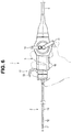
- Fig. 6 is a side view illustrating a configuration of an endoscope apparatus according to a second modification
- Fig. 7 is a side view illustrating a configuration of an endoscope apparatus according to a third modification.
- an endoscope apparatus 1 which is a bendable rigid endoscope, mainly includes a long insertion portion 2, an operation portion 3 provided so as to be continuous with a proximal end of the insertion portion 2, a light guide connector 4 to be connected to a non-illustrated light source apparatus, and a video connector 5 to be connected to a non-illustrated video system center.
- the operation portion 3 and the light guide connector 4 are connected via a universal cable 6, which is a flexible cable, and the light guide connector 4 and the video connector 5 are connected via a communication cable 7.
- a distal end portion 11 mainly formed of a metal member of, e.g., stainless steel, a flexible bending portion 12 and a rigid tube 13 that is a metal tube of, e.g., stainless steel are provided continuously in this order from the distal end side.
- the insertion portion 2 is a part to be inserted into a body, and includes, e.g., non-illustrated cables and light guides incorporated inside.
- the operation portion 3 includes angle levers 14, 15 for remotely operating the bending portion 12, various switches 16 (see Fig. 2 ) for operating, e.g., the light source apparatus or the video system center, and a finger rest/holding portion 17 that allows a finger of a user to be inserted and hooked in the finger rest/holding portion 17.
- the angle levers 14, 15 provide bending operation means that enables the bending portion 12 of the insertion portion 2 to be operated in four, up/down and right/left, directions, that is, fully circumferentially.
- the bending portion 12 may be configured so as to bend only in two, up/down, directions.
- the angle lever 14 serves to remotely operate the bending portion 12
- the angle lever 15 serves as a fixing lever for fixing a bent state of the bending portion 12.
- the above-described endoscope apparatus 1 is a bendable rigid endoscope that is what is a rigid endoscope used in a laparoscopic surgical operation, which includes an insertion portion 2, a large part other than the bending portion 12 of which is rigid.
- the finger rest/holding portion 17 includes a finger rest portion 22 having a ring-like shape, here, which is a finger rest groove into which, for example, a ring finger of a user is inserted in such a manner as indicated by the alternate long and two short dashes line in Fig. 2 , and an annular fitting portion 21 fitted to the operation portion 3 so as to be pivotable around a longitudinal axis X.
- a finger rest portion 22 having a ring-like shape, here, which is a finger rest groove into which, for example, a ring finger of a user is inserted in such a manner as indicated by the alternate long and two short dashes line in Fig. 2 , and an annular fitting portion 21 fitted to the operation portion 3 so as to be pivotable around a longitudinal axis X.
- the finger rest/holding portion 17 is fitted by putting the fitting portion 21 on a pivot holding portion 31 provided at a distal end part of the operation portion 3, the pivot holding portion 31 providing a ring pivoting shaft and having an exact circle shape in cross-section.
- the fitting portion 21 of the finger rest/holding portion 17 is fitted from the distal end side of the pivot holding portion 31 until the fitting portion 21 abuts on a distal end face of a radially-projecting bulge portion 32 formed on the proximal end side of the pivot holding portion 31.
- a round plate ring-like retainer member 35 including a hole portion formed at a center is fixed to the pivot holding portion 31 via two screws 39, here, in such a manner that the round plate ring-like retainer member 35 abuts on a distal end face of the fitting portion 21. Note that, in the hole portion of the retainer member 35, a pipe sleeve portion 33 connected to the insertion portion 2 is inserted.
- the retainer member 35 includes a recess portion 36 formed on the distal end side, and in the recess portion 36, insertion holes 37, through which the two screws 39 are inserted, respectively, are formed at two positions that are symmetrical with respect to a center point here.
- the two screws 39 are threadably connected to respective screw holes 34 formed in a distal end face of the pivot holding portion 31, via the respective insertion holes 37 of the retainer member 35. Consequently, the retainer member 35 is fixed to the pivot holding portion 31.
- a round plate ring-like decorative cover 38 is bonded to the recess portion 36 of the retainer member 35 so as to prevent exposure of the screws 39.
- a hole portion, through which the pipe sleeve portion 33 connected to the insertion portion 2 is inserted, is formed at a center.
- the distal end side of the fitting portion 21 of the finger rest/holding portion 17 abuts on the retainer member 35, and the proximal end side of the fitting portion 21 abuts on the bulge portion 32, and the fitting portion 21 is thus fitted to the distal end part of the operation portion 3 so as to be pivotable around the longitudinal axis X of the operation portion 3 and so as not to come off from the pivot holding portion 31.
- the insertion portion 2 of the endoscope apparatus 1 configured as above is introduced into, for example, an abdominal cavity via, e.g., a trocar punctured and inserted in a patient during a laparoscopic surgical operation.
- the user when a user grasps the endoscope apparatus 1 horizontally from a side, the user can grasp the operation portion 3 with a finger, for example, the ring finger of his/her hand inserted in the finger rest portion 22 of the finger rest/holding portion 17 as indicated by the alternate long and two short dashes line in Fig. 2 .
- a finger for example, the ring finger of his/her hand inserted in the finger rest portion 22 of the finger rest/holding portion 17 as indicated by the alternate long and two short dashes line in Fig. 2 .
- the insertion of the finger of his/her hand in the finger rest portion 22 of the finger rest/holding portion 17 reduces strain on the thumb supporting the weight of the endoscope apparatus 1 and thus reduces the degree of fatigue during long-time surgery.
- the finger rest/holding portion 17 is pivotable around the longitudinal axis X of the operation portion 3 and thus can be moved to a desired pivotal position that allows the user to easily grasp the finger rest/holding portion 17.
- the endoscope apparatus 1 enables enhancement in capability of holding the operation portion 3 and significant reduction in degree of fatigue of a user during a long-time operation.
- a plurality of, here, three O-shaped rings 41 which are resistive members that increase frictional resistance between the inner circumferential face of the fitting portion 21 and an outer circumferential face of the pivot holding portion 31 and adjust an amount of force required for movement around the longitudinal direction X of the operation portion 3 may be provided.
- the finger rest/holding portion 17 is less likely to be easily displaced from a desired pivotal position to which the finger rest/holding portion 17 has been moved by the user, enhancing a holding capability for maintaining the pivotal position.
- the resistive members are not limited to the O-shaped rings 41, and any of various components that provide frictional resistance enhancement such as a rubber tube may be employed.
- the inside of the fitting portion 21 of the finger rest/holding portion 17 is held in a water-tight manner even if the fitting portion 21 pivots, by an O-shaped ring 42, which is a water-tightness holding member on the retainer member 35, on the distal end side and an O-shaped ring 43, which is a water-tightness holding member abutting on the bulge portion 32, on the proximal end side.
- water-tightness holding members are not limited to the O-shaped rings 42 and 43, and any of various seal structures may be employed.
- the endoscope apparatus 1 eliminates a need to remove the finger rest/holding portion 17 from the operation portion 3 for, e.g., cleaning, disinfection and/or sterilization before and after use and enables e.g., cleaning, disinfection and/or sterilization with the finger rest/holding portion 17 fitted to the operation portion 3.
- a finger rest portion 22 of a finger rest/holding portion 17 may have a horizontally-long shape widen along a longitudinal axis X of an operation portion 3 so as to allow a user to insert a plurality of fingers, here, two fingers, for example, a ring finger and a middle finger to the finger rest portion 22 as indicated in the alternate long and two short dashes line.
- the endoscope apparatus 1 enables a position of the operation portion 3 to be more reliably held by insertion of two or more fingers to the finger rest portion 22 of the finger rest/holding portion 17 relative to insertion of one finger to the finger rest portion 22 of the finger rest/holding portion 17, without the operation portion 3 rotating (tilting) around the fingers, in addition to provision of various operation and effects described above.
- a finger rest portion 22 of a finger rest/holding portion 17 is not limited to a ring-like shape and may have a horizontal U shape having a wall portion in the angle lever 14, 15 direction, which is the proximal end direction.
- the finger rest portion 22, which is a finger rest groove, here, is open on the distal end side so as to enable, for example, a ring finger to be easily introduced from the distal end side of the endoscope apparatus 1, which is different from a ring-like shape.
- the wall portion is provided on the proximal end side in the angle lever 14, 15 direction of the finger rest portion 22 so as to allow a ring finger to be caught and allow strength to be easily put in a thumb and an index finger operating the angle levers 14, 15, and ensure the capability of holding the operation portion 3 by holding the wall portion of the finger rest portion 22, for example, between the ring finger and the middle finger.
- a hook portion 18 on which a thumb of a user is to be hooked and held may be provided between various switches 16 and an angle lever 14 of an operation portion 3 on the side substantially opposite to a position of a finger rest portion 22 of a finger rest/holding portion 17.
- the hook portion 18 is provided on the side on which a finger, here, a thumb, of a user is positioned which holds and grasps the operation portion 3 with another finger, here, e.g., a ring finger, of the user which is inserted in the finger rest portion 22 of the finger rest/holding portion 17.
- the endoscope apparatus 1 provides a further enhanced holding capability by, for example, the ring finger of the user being inserted into the finger rest portion 22 of the holding portion 17 and the thumb of the user being hooked on the hook portion 18 so as to abut on the proximal end side of the hook portion 18.
- a configuration with such elements deleted may be extracted as an aspect of the invention if such configuration can solve a problem to be solved by the invention and provide an effect of the invention.
Landscapes
- Health & Medical Sciences (AREA)
- Life Sciences & Earth Sciences (AREA)
- Physics & Mathematics (AREA)
- Surgery (AREA)
- Optics & Photonics (AREA)
- Biomedical Technology (AREA)
- Animal Behavior & Ethology (AREA)
- Radiology & Medical Imaging (AREA)
- Nuclear Medicine, Radiotherapy & Molecular Imaging (AREA)
- Engineering & Computer Science (AREA)
- Biophysics (AREA)
- Heart & Thoracic Surgery (AREA)
- Medical Informatics (AREA)
- Molecular Biology (AREA)
- Pathology (AREA)
- General Health & Medical Sciences (AREA)
- Public Health (AREA)
- Veterinary Medicine (AREA)
- Astronomy & Astrophysics (AREA)
- General Physics & Mathematics (AREA)
- Instruments For Viewing The Inside Of Hollow Bodies (AREA)
- Endoscopes (AREA)
Abstract
Description
- The present invention relates to a bendable rigid endoscope including a rigid insertion portion, such as those used in, e.g., a laparoscopic surgical operation.
- In recent years, in the medical field and the industrial field, endoscope systems for observing the inside of a body cavity or the inside of an apparatus have widely been used.
- In particular, in the medical field, various types of endoscopes such as bendable rigid endoscopes, which serve as surgical endoscopes suitable for use in observing, or performing treatment such as an operation of, the inside of an abdominal cavity by inserting an insertion portion from a hole poked in a body surface of, e.g., an abdominal part, as well as flexible endoscopes suitable for use in observing, or performing various treatment of, the inside of a digestive organ such as an esophagus, a stomach or a large bowel by inserting an insertion portion from an organ orifice such as a mouth cavity or an anus, have been in practical use.
- Among these endoscopes, for example, as disclosed in Japanese Patent Application Laid-Open Publication No.
2012-45326 - However, conventional bendable rigid endoscopes such as the one disclosed in Japanese Patent Application Laid-Open Publication No.
2012-45326 - More specifically, for example, when a user wishes to grasp a bendable rigid endoscope used in laparoscopic surgery horizontally from a side, if the user grasps the operation portion so that the back of his/her hand faces upward to prevent the wrist of the user from being strained, large strain is put on the thumb that supports the weight of the abdominal endoscope, and thus, there has been a need for reduction in degree of fatigue during a long-time operation.
- Therefore, the present invention has been made in view of the above problem, and an object of the present invention is to provide a bendable rigid endoscope that enables enhancement in capability of holding an operation portion and reduction in degree of fatigue of a user during a long-time operation.
- A bendable rigid endoscope according to an aspect of the present invention includes: a rigid insertion portion; a flexible bending portion provided at a distal end part of the insertion portion; an operation portion provided so as to be continuous with the insertion portion, an angle lever for bending the bending portion being provided at the operation portion; and a finger rest/holding portion including a finger rest groove that allows a finger of a user to be inserted to the finger rest groove when the user holds the operation portion, the finger rest/holding portion being provided on the insertion portion side of the operation portion relative to the angle lever in such a manner that the finger rest groove is pivotable around a longitudinal axis of the operation portion.
- The above present invention enables provision of a bendable rigid endoscope that enables enhancement in capability of holding an operation portion and reduction in degree of fatigue of a user during a long-time operation.
-
-
Fig. 1 is a perspective view illustrating an overall configuration of an endoscope apparatus according to an aspect of the present invention; -
Fig. 2 is a side view of a configuration of the endoscope apparatus according to the aspect of the present invention; -
Fig. 3 is a partial perspective view for describing fitting of a finger rest/holding portion to an operation portion, according to the aspect of the present invention; -
Fig. 4 is a partial cross-sectional view of a distal end part of the operation portion at which the finger rest/holding portion is provided, according to the aspect of the present invention; -
Fig. 5 is a side view illustrating a configuration of an endoscope apparatus according to a first modification of the aspect of the present invention; -
Fig. 6 is a side view illustrating a configuration of an endoscope apparatus according to a second modification of the aspect of the present invention; and -
Fig. 7 is a side view illustrating a configuration of an endoscope apparatus according to a third modification of the aspect of the present invention. - An endoscope apparatus, which is an abdominal endoscope, according to the present invention will be described below. Note that in the below description, the drawings based on the respective embodiments are schematic ones and, e.g., a relationship between a thickness and a width of each part and ratios in thickness among the respective parts are different from actual ones, and parts that are different in dimensional relationship and ratio depending on the drawings may be included in the drawings.
- First, a bendable rigid endoscope according to an aspect of the present invention will be described with reference to the drawings.
Fig. 1 is a perspective view illustrating an overall configuration of an endoscope apparatus that is a bendable rigid endoscope;Fig. 2 is a side view illustrating a configuration of the endoscope apparatus;Fig. 3 is a partial perspective view for describing fitting of a finger rest/holding portion to an operation portion;Fig. 4 is a partial cross-sectional view of a distal end part of the operation portion at which the finger rest/holding portion is provided;Fig. 5 is a side view illustrating a configuration of an endoscope apparatus according to a first modification;Fig. 6 is a side view illustrating a configuration of an endoscope apparatus according to a second modification; andFig. 7 is a side view illustrating a configuration of an endoscope apparatus according to a third modification. - As illustrated in
Fig. 1 , anendoscope apparatus 1, which is a bendable rigid endoscope, mainly includes along insertion portion 2, anoperation portion 3 provided so as to be continuous with a proximal end of theinsertion portion 2, alight guide connector 4 to be connected to a non-illustrated light source apparatus, and avideo connector 5 to be connected to a non-illustrated video system center. - Here, in the
endoscope apparatus 1, theoperation portion 3 and thelight guide connector 4 are connected via auniversal cable 6, which is a flexible cable, and thelight guide connector 4 and thevideo connector 5 are connected via acommunication cable 7. - In the
insertion portion 2, adistal end portion 11 mainly formed of a metal member of, e.g., stainless steel, aflexible bending portion 12 and arigid tube 13 that is a metal tube of, e.g., stainless steel are provided continuously in this order from the distal end side. Theinsertion portion 2 is a part to be inserted into a body, and includes, e.g., non-illustrated cables and light guides incorporated inside. - The
operation portion 3 includes angle levers 14, 15 for remotely operating thebending portion 12, various switches 16 (seeFig. 2 ) for operating, e.g., the light source apparatus or the video system center, and a finger rest/holding portion 17 that allows a finger of a user to be inserted and hooked in the finger rest/holding portion 17. - The angle levers 14, 15 provide bending operation means that enables the
bending portion 12 of theinsertion portion 2 to be operated in four, up/down and right/left, directions, that is, fully circumferentially. - Note that the
bending portion 12 may be configured so as to bend only in two, up/down, directions. In such case, theangle lever 14 serves to remotely operate thebending portion 12, and theangle lever 15 serves as a fixing lever for fixing a bent state of thebending portion 12. - The above-described
endoscope apparatus 1 according to the present embodiment is a bendable rigid endoscope that is what is a rigid endoscope used in a laparoscopic surgical operation, which includes aninsertion portion 2, a large part other than thebending portion 12 of which is rigid. - Here, a configuration of the finger rest/
holding portion 17 provided at theendoscope apparatus 1 according to the present embodiment will be described in detail below. - As illustrated in
Fig. 3 , the finger rest/holding portion 17 includes afinger rest portion 22 having a ring-like shape, here, which is a finger rest groove into which, for example, a ring finger of a user is inserted in such a manner as indicated by the alternate long and two short dashes line inFig. 2 , and anannular fitting portion 21 fitted to theoperation portion 3 so as to be pivotable around a longitudinal axis X. - The finger rest/
holding portion 17 is fitted by putting thefitting portion 21 on apivot holding portion 31 provided at a distal end part of theoperation portion 3, thepivot holding portion 31 providing a ring pivoting shaft and having an exact circle shape in cross-section. - Here, the
fitting portion 21 of the finger rest/holding portion 17 is fitted from the distal end side of thepivot holding portion 31 until thefitting portion 21 abuts on a distal end face of a radially-projectingbulge portion 32 formed on the proximal end side of thepivot holding portion 31. - Then, a round plate ring-
like retainer member 35 including a hole portion formed at a center is fixed to thepivot holding portion 31 via twoscrews 39, here, in such a manner that the round plate ring-like retainer member 35 abuts on a distal end face of thefitting portion 21. Note that, in the hole portion of theretainer member 35, apipe sleeve portion 33 connected to theinsertion portion 2 is inserted. - The
retainer member 35 includes arecess portion 36 formed on the distal end side, and in therecess portion 36,insertion holes 37, through which the twoscrews 39 are inserted, respectively, are formed at two positions that are symmetrical with respect to a center point here. - The two
screws 39 are threadably connected torespective screw holes 34 formed in a distal end face of thepivot holding portion 31, via therespective insertion holes 37 of theretainer member 35. Consequently, theretainer member 35 is fixed to thepivot holding portion 31. - Note that a round plate ring-like
decorative cover 38 is bonded to therecess portion 36 of theretainer member 35 so as to prevent exposure of thescrews 39. In thisdecorative cover 38, also, a hole portion, through which thepipe sleeve portion 33 connected to theinsertion portion 2 is inserted, is formed at a center. - As described above, the distal end side of the
fitting portion 21 of the finger rest/holding portion 17 abuts on theretainer member 35, and the proximal end side of thefitting portion 21 abuts on thebulge portion 32, and thefitting portion 21 is thus fitted to the distal end part of theoperation portion 3 so as to be pivotable around the longitudinal axis X of theoperation portion 3 and so as not to come off from thepivot holding portion 31. - The
insertion portion 2 of theendoscope apparatus 1 configured as above is introduced into, for example, an abdominal cavity via, e.g., a trocar punctured and inserted in a patient during a laparoscopic surgical operation. - In this case, when a user grasps the
endoscope apparatus 1 horizontally from a side, the user can grasp theoperation portion 3 with a finger, for example, the ring finger of his/her hand inserted in thefinger rest portion 22 of the finger rest/holding portion 17 as indicated by the alternate long and two short dashes line inFig. 2 . - Therefore, even if the user grasps the operation portion with the back of the hand facing upward, the insertion of the finger of his/her hand in the
finger rest portion 22 of the finger rest/holding portion 17 reduces strain on the thumb supporting the weight of theendoscope apparatus 1 and thus reduces the degree of fatigue during long-time surgery. - In other words, even if the user opens the hand grasping the
operation portion 3, the finger of his/her hand inserted in thefinger rest portion 22 of the finger rest/holding portion 17 is caught, and thus, the position of theendoscope apparatus 1 is held without theendoscope apparatus 1 dropping down vertically. - Furthermore, the finger rest/
holding portion 17 is pivotable around the longitudinal axis X of theoperation portion 3 and thus can be moved to a desired pivotal position that allows the user to easily grasp the finger rest/holding portion 17. - According to the above, the
endoscope apparatus 1 according to the present embodiment enables enhancement in capability of holding theoperation portion 3 and significant reduction in degree of fatigue of a user during a long-time operation. - Note that, as illustrated in
Fig. 4 , on an inner circumferential face of thefitting portion 21 of the finger rest/holding portion 17, a plurality of, here, three O-shaped rings 41, which are resistive members that increase frictional resistance between the inner circumferential face of thefitting portion 21 and an outer circumferential face of thepivot holding portion 31 and adjust an amount of force required for movement around the longitudinal direction X of theoperation portion 3 may be provided. - Consequently, the finger rest/
holding portion 17 is less likely to be easily displaced from a desired pivotal position to which the finger rest/holding portion 17 has been moved by the user, enhancing a holding capability for maintaining the pivotal position. - Here, the resistive members are not limited to the O-
shaped rings 41, and any of various components that provide frictional resistance enhancement such as a rubber tube may be employed. - Also, the inside of the
fitting portion 21 of the finger rest/holding portion 17 is held in a water-tight manner even if thefitting portion 21 pivots, by an O-shaped ring 42, which is a water-tightness holding member on theretainer member 35, on the distal end side and an O-shaped ring 43, which is a water-tightness holding member abutting on thebulge portion 32, on the proximal end side. - Here, the water-tightness holding members are not limited to the O-
shaped rings - Consequently, the
endoscope apparatus 1 eliminates a need to remove the finger rest/holding portion 17 from theoperation portion 3 for, e.g., cleaning, disinfection and/or sterilization before and after use and enables e.g., cleaning, disinfection and/or sterilization with the finger rest/holding portion 17 fitted to theoperation portion 3. - As illustrated in
Fig. 5 , afinger rest portion 22 of a finger rest/holding portion 17 may have a horizontally-long shape widen along a longitudinal axis X of anoperation portion 3 so as to allow a user to insert a plurality of fingers, here, two fingers, for example, a ring finger and a middle finger to thefinger rest portion 22 as indicated in the alternate long and two short dashes line. - With such configuration, the
endoscope apparatus 1 enables a position of theoperation portion 3 to be more reliably held by insertion of two or more fingers to thefinger rest portion 22 of the finger rest/holding portion 17 relative to insertion of one finger to thefinger rest portion 22 of the finger rest/holding portion 17, without theoperation portion 3 rotating (tilting) around the fingers, in addition to provision of various operation and effects described above. - As illustrated in
Fig. 6 , afinger rest portion 22 of a finger rest/holding portion 17 is not limited to a ring-like shape and may have a horizontal U shape having a wall portion in theangle lever finger rest portion 22, which is a finger rest groove, here, is open on the distal end side so as to enable, for example, a ring finger to be easily introduced from the distal end side of theendoscope apparatus 1, which is different from a ring-like shape. - Here, the wall portion is provided on the proximal end side in the
angle lever finger rest portion 22 so as to allow a ring finger to be caught and allow strength to be easily put in a thumb and an index finger operating the angle levers 14, 15, and ensure the capability of holding theoperation portion 3 by holding the wall portion of thefinger rest portion 22, for example, between the ring finger and the middle finger. - As illustrated in
Fig. 7 , ahook portion 18 on which a thumb of a user is to be hooked and held may be provided betweenvarious switches 16 and anangle lever 14 of anoperation portion 3 on the side substantially opposite to a position of afinger rest portion 22 of a finger rest/holdingportion 17. - In other words, the
hook portion 18 is provided on the side on which a finger, here, a thumb, of a user is positioned which holds and grasps theoperation portion 3 with another finger, here, e.g., a ring finger, of the user which is inserted in thefinger rest portion 22 of the finger rest/holdingportion 17. - Consequently, the
endoscope apparatus 1 provides a further enhanced holding capability by, for example, the ring finger of the user being inserted into thefinger rest portion 22 of the holdingportion 17 and the thumb of the user being hooked on thehook portion 18 so as to abut on the proximal end side of thehook portion 18. - The invention described in the above embodiment is not limited to the embodiment and the modifications of the embodiment, and in the practical phase, various other modifications are possible without departing from the spirit of the invention. Furthermore, the above-described embodiment includes various phases of the invention, and various aspects of the invention may be extracted by appropriate combinations of the plurality of elements disclosed.
- For example, even where some elements are deleted from all the elements indicated in the embodiment, a configuration with such elements deleted may be extracted as an aspect of the invention if such configuration can solve a problem to be solved by the invention and provide an effect of the invention.
- The present application is filed claiming priority from Japanese Patent Application No.
2015-073084
Claims (7)
- A bendable rigid endoscope comprising:a rigid insertion portion;a flexible bending portion provided at a distal end part of the insertion portion;an operation portion provided so as to be continuous with the insertion portion, an angle lever for bending the bending portion being provided at the operation portion; anda finger rest/holding portion including a finger rest groove that allows a finger of a user to be inserted to the finger rest groove when the user holds the operation portion, the finger rest/holding portion being provided on the insertion portion side of the operation portion relative to the angle lever in such a manner that the finger rest groove is pivotable around a longitudinal axis of the operation portion.
- The bendable rigid endoscope according to claim 1, wherein a resistive member that adjusts an amount of force required for movement of the finger rest groove around the longitudinal axis is provided.
- The bendable rigid endoscope according to claim 1 or 2, wherein a water-tightness holding member that holds the finger rest/holding portion and the operation portion in a water-tight manner is provided.
- The bendable rigid endoscope according to any one of claims 1 to 3, wherein the finger rest portion is formed in a ring-like shape.
- The bendable rigid endoscope according to claim 4, wherein the finger rest portion is formed in the ring-like shape that is horizontally long in the longitudinal axis direction of the operation portion so that a plurality of fingers of the user can be inserted to the finger rest portion.
- The bendable rigid endoscope according to any one of claims 1 to 3, wherein the finger rest portion is formed in a horizontal U shape, a distal end side of the finger rest portion being open.
- The bendable rigid endoscope according to any one of claims 1 to 6, comprising a hook portion provided at the operation portion, on a side on which a finger of the user is positioned, the finger holding and grasping the operation portion with another finger of the user, the other finger being inserted in the finger rest portion.
Applications Claiming Priority (2)
| Application Number | Priority Date | Filing Date | Title |
|---|---|---|---|
| JP2015073084 | 2015-03-31 | ||
| PCT/JP2015/078061 WO2016157578A1 (en) | 2015-03-31 | 2015-10-02 | Curved rigid endoscope |
Publications (2)
| Publication Number | Publication Date |
|---|---|
| EP3195785A1 true EP3195785A1 (en) | 2017-07-26 |
| EP3195785A4 EP3195785A4 (en) | 2018-04-04 |
Family
ID=57006649
Family Applications (1)
| Application Number | Title | Priority Date | Filing Date |
|---|---|---|---|
| EP15887720.9A Withdrawn EP3195785A4 (en) | 2015-03-31 | 2015-10-02 | Curved rigid endoscope |
Country Status (5)
| Country | Link |
|---|---|
| US (1) | US20170209025A1 (en) |
| EP (1) | EP3195785A4 (en) |
| JP (1) | JP6087027B1 (en) |
| CN (1) | CN107072484B (en) |
| WO (1) | WO2016157578A1 (en) |
Families Citing this family (6)
| Publication number | Priority date | Publication date | Assignee | Title |
|---|---|---|---|---|
| JP7633166B2 (en) * | 2019-01-18 | 2025-02-19 | アイピージー フォトニクス コーポレーション | Ergonomic steering wheel |
| CN109875489A (en) * | 2019-03-26 | 2019-06-14 | 江阴市人民医院 | a bronchoscope |
| EP4130844B1 (en) * | 2020-03-27 | 2026-01-28 | FUJIFILM Corporation | Endoscope |
| EP4223208A1 (en) | 2022-02-07 | 2023-08-09 | Ambu A/S | An endoscope |
| EP4566510A1 (en) | 2023-12-08 | 2025-06-11 | Karl Storz SE & Co. KG | Surgical instrument and surgical system |
| JP2026061622A (en) * | 2024-09-30 | 2026-04-09 | 富士フイルム株式会社 | Operating levers, medical devices, ultrasound probes, and endoscopes |
Family Cites Families (16)
| Publication number | Priority date | Publication date | Assignee | Title |
|---|---|---|---|---|
| JPS6240561Y2 (en) * | 1981-02-26 | 1987-10-17 | ||
| US5088998A (en) * | 1988-09-16 | 1992-02-18 | Olympus Optical Co., Ltd. | Resectoscope apparatus |
| US6033378A (en) * | 1990-02-02 | 2000-03-07 | Ep Technologies, Inc. | Catheter steering mechanism |
| US5152278A (en) * | 1990-08-28 | 1992-10-06 | Applied Medical Resources, Inc. | Surgical endoscope apparatus |
| DE9209180U1 (en) * | 1992-07-09 | 1993-11-11 | Medizin-Technische-Werkstätte Arzt- und Krankenhausbedarf Wolfgang Haag, 46487 Wesel | Handle for probes that can be inserted into endoscopes |
| JP2002112945A (en) * | 2000-10-11 | 2002-04-16 | Asahi Optical Co Ltd | Operation unit of endoscope |
| JP2002282199A (en) * | 2001-03-28 | 2002-10-02 | Asahi Optical Co Ltd | Operation unit of endoscope |
| JP2005237817A (en) * | 2004-02-27 | 2005-09-08 | Olympus Corp | Endoscope |
| JP4472382B2 (en) * | 2004-02-27 | 2010-06-02 | オリンパス株式会社 | Endoscope |
| WO2005082227A1 (en) * | 2004-02-27 | 2005-09-09 | Olympus Corporation | Endoscope and endoscope system |
| JP2006149880A (en) * | 2004-11-30 | 2006-06-15 | Olympus Medical Systems Corp | Endoscope operation unit |
| CN102711581B (en) * | 2010-12-24 | 2014-01-29 | 奥林巴斯株式会社 | Endoscopic device |
| JP5602619B2 (en) * | 2010-12-28 | 2014-10-08 | オリンパス株式会社 | Endoscope |
| US9162036B2 (en) * | 2011-12-30 | 2015-10-20 | Biosense Webster (Israel), Ltd. | Medical device control handle with multiple puller wires |
| WO2013106444A1 (en) * | 2012-01-10 | 2013-07-18 | Boston Scientific Scimed, Inc. | A steerable medical device having an imaging system |
| TWI537017B (en) * | 2012-03-13 | 2016-06-11 | 林雀虹 | Intubation assist device |
-
2015
- 2015-10-02 WO PCT/JP2015/078061 patent/WO2016157578A1/en not_active Ceased
- 2015-10-02 JP JP2016542300A patent/JP6087027B1/en active Active
- 2015-10-02 CN CN201580058280.4A patent/CN107072484B/en active Active
- 2015-10-02 EP EP15887720.9A patent/EP3195785A4/en not_active Withdrawn
-
2017
- 2017-04-10 US US15/483,204 patent/US20170209025A1/en not_active Abandoned
Also Published As
| Publication number | Publication date |
|---|---|
| CN107072484B (en) | 2018-12-14 |
| CN107072484A (en) | 2017-08-18 |
| JP6087027B1 (en) | 2017-03-01 |
| JPWO2016157578A1 (en) | 2017-04-27 |
| US20170209025A1 (en) | 2017-07-27 |
| WO2016157578A1 (en) | 2016-10-06 |
| EP3195785A4 (en) | 2018-04-04 |
Similar Documents
| Publication | Publication Date | Title |
|---|---|---|
| US20170209025A1 (en) | Bendable rigid endoscope | |
| US11311177B2 (en) | Endoscope and endoscope system | |
| JP4477519B2 (en) | Endoscope | |
| EP2512317B1 (en) | Selectively positionable camera for surgical guide tube assembly | |
| EP2105084B1 (en) | Medical apparatus | |
| JP4323441B2 (en) | Endoscope | |
| EP3155952A1 (en) | Biopsy system | |
| JP2007289703A (en) | Medical cannula and medical cannula system | |
| EP2085034A1 (en) | Endoscope treatment instrument | |
| US11006936B2 (en) | Control assemblies for medical devices and related methods of use | |
| JP2015047376A (en) | Tube device with puncture function | |
| EP2534999B1 (en) | Endoscope-holding device and endoscopic system | |
| WO2015194263A1 (en) | Guide apparatus and surgery system | |
| CN115515507A (en) | Hinge mechanism and how to use it | |
| JPWO2015174128A1 (en) | Endoscope | |
| JP3722732B2 (en) | Endoscope | |
| JP5646373B2 (en) | Endoscope | |
| JP2012065753A (en) | Surgical endoscope apparatus |
Legal Events
| Date | Code | Title | Description |
|---|---|---|---|
| STAA | Information on the status of an ep patent application or granted ep patent |
Free format text: STATUS: THE INTERNATIONAL PUBLICATION HAS BEEN MADE |
|
| PUAI | Public reference made under article 153(3) epc to a published international application that has entered the european phase |
Free format text: ORIGINAL CODE: 0009012 |
|
| STAA | Information on the status of an ep patent application or granted ep patent |
Free format text: STATUS: REQUEST FOR EXAMINATION WAS MADE |
|
| 17P | Request for examination filed |
Effective date: 20170420 |
|
| AK | Designated contracting states |
Kind code of ref document: A1 Designated state(s): AL AT BE BG CH CY CZ DE DK EE ES FI FR GB GR HR HU IE IS IT LI LT LU LV MC MK MT NL NO PL PT RO RS SE SI SK SM TR |
|
| AX | Request for extension of the european patent |
Extension state: BA ME |
|
| A4 | Supplementary search report drawn up and despatched |
Effective date: 20180306 |
|
| RIC1 | Information provided on ipc code assigned before grant |
Ipc: G02B 23/24 20060101ALI20180228BHEP Ipc: A61B 1/00 20060101AFI20180228BHEP Ipc: A61M 25/01 20060101ALI20180228BHEP |
|
| DAV | Request for validation of the european patent (deleted) | ||
| DAX | Request for extension of the european patent (deleted) | ||
| STAA | Information on the status of an ep patent application or granted ep patent |
Free format text: STATUS: EXAMINATION IS IN PROGRESS |
|
| 17Q | First examination report despatched |
Effective date: 20191023 |
|
| STAA | Information on the status of an ep patent application or granted ep patent |
Free format text: STATUS: THE APPLICATION IS DEEMED TO BE WITHDRAWN |
|
| 18D | Application deemed to be withdrawn |
Effective date: 20200303 |