EP3195738A2 - Ceramic vaporizer and electronic cigarettes having the ceramic vaporizer - Google Patents
Ceramic vaporizer and electronic cigarettes having the ceramic vaporizer Download PDFInfo
- Publication number
- EP3195738A2 EP3195738A2 EP16155412.6A EP16155412A EP3195738A2 EP 3195738 A2 EP3195738 A2 EP 3195738A2 EP 16155412 A EP16155412 A EP 16155412A EP 3195738 A2 EP3195738 A2 EP 3195738A2
- Authority
- EP
- European Patent Office
- Prior art keywords
- vaporizer
- air
- heating elements
- electronic cigarette
- ceramic
- Prior art date
- Legal status (The legal status is an assumption and is not a legal conclusion. Google has not performed a legal analysis and makes no representation as to the accuracy of the status listed.)
- Granted
Links
- 239000006200 vaporizer Substances 0.000 title claims abstract description 109
- 239000003571 electronic cigarette Substances 0.000 title claims abstract description 63
- 239000000919 ceramic Substances 0.000 title claims abstract description 60
- 239000007788 liquid Substances 0.000 claims abstract description 79
- 238000010438 heat treatment Methods 0.000 claims abstract description 67
- 239000000956 alloy Substances 0.000 claims abstract description 8
- 229910045601 alloy Inorganic materials 0.000 claims abstract description 8
- PXHVJJICTQNCMI-UHFFFAOYSA-N Nickel Chemical compound [Ni] PXHVJJICTQNCMI-UHFFFAOYSA-N 0.000 claims description 15
- BASFCYQUMIYNBI-UHFFFAOYSA-N platinum Chemical compound [Pt] BASFCYQUMIYNBI-UHFFFAOYSA-N 0.000 claims description 15
- 239000000835 fiber Substances 0.000 claims description 12
- 239000011651 chromium Substances 0.000 claims description 10
- 239000010949 copper Substances 0.000 claims description 10
- 239000010931 gold Substances 0.000 claims description 10
- 239000011572 manganese Substances 0.000 claims description 10
- 239000010955 niobium Substances 0.000 claims description 10
- 238000007789 sealing Methods 0.000 claims description 10
- 238000009413 insulation Methods 0.000 claims description 8
- 229910010293 ceramic material Inorganic materials 0.000 claims description 7
- VYZAMTAEIAYCRO-UHFFFAOYSA-N Chromium Chemical compound [Cr] VYZAMTAEIAYCRO-UHFFFAOYSA-N 0.000 claims description 5
- RYGMFSIKBFXOCR-UHFFFAOYSA-N Copper Chemical compound [Cu] RYGMFSIKBFXOCR-UHFFFAOYSA-N 0.000 claims description 5
- 229920000742 Cotton Polymers 0.000 claims description 5
- XEEYBQQBJWHFJM-UHFFFAOYSA-N Iron Chemical compound [Fe] XEEYBQQBJWHFJM-UHFFFAOYSA-N 0.000 claims description 5
- PWHULOQIROXLJO-UHFFFAOYSA-N Manganese Chemical compound [Mn] PWHULOQIROXLJO-UHFFFAOYSA-N 0.000 claims description 5
- 239000004743 Polypropylene Substances 0.000 claims description 5
- BQCADISMDOOEFD-UHFFFAOYSA-N Silver Chemical compound [Ag] BQCADISMDOOEFD-UHFFFAOYSA-N 0.000 claims description 5
- 229920004933 Terylene® Polymers 0.000 claims description 5
- XAGFODPZIPBFFR-UHFFFAOYSA-N aluminium Chemical compound [Al] XAGFODPZIPBFFR-UHFFFAOYSA-N 0.000 claims description 5
- 229910052782 aluminium Inorganic materials 0.000 claims description 5
- 229910052793 cadmium Inorganic materials 0.000 claims description 5
- BDOSMKKIYDKNTQ-UHFFFAOYSA-N cadmium atom Chemical compound [Cd] BDOSMKKIYDKNTQ-UHFFFAOYSA-N 0.000 claims description 5
- 229910052804 chromium Inorganic materials 0.000 claims description 5
- 229910017052 cobalt Inorganic materials 0.000 claims description 5
- 239000010941 cobalt Substances 0.000 claims description 5
- GUTLYIVDDKVIGB-UHFFFAOYSA-N cobalt atom Chemical compound [Co] GUTLYIVDDKVIGB-UHFFFAOYSA-N 0.000 claims description 5
- 229910052802 copper Inorganic materials 0.000 claims description 5
- PCHJSUWPFVWCPO-UHFFFAOYSA-N gold Chemical compound [Au] PCHJSUWPFVWCPO-UHFFFAOYSA-N 0.000 claims description 5
- 229910052737 gold Inorganic materials 0.000 claims description 5
- 229910052741 iridium Inorganic materials 0.000 claims description 5
- GKOZUEZYRPOHIO-UHFFFAOYSA-N iridium atom Chemical compound [Ir] GKOZUEZYRPOHIO-UHFFFAOYSA-N 0.000 claims description 5
- 229910052748 manganese Inorganic materials 0.000 claims description 5
- 229910052759 nickel Inorganic materials 0.000 claims description 5
- 229910052758 niobium Inorganic materials 0.000 claims description 5
- GUCVJGMIXFAOAE-UHFFFAOYSA-N niobium atom Chemical compound [Nb] GUCVJGMIXFAOAE-UHFFFAOYSA-N 0.000 claims description 5
- 229920001778 nylon Polymers 0.000 claims description 5
- 229910052697 platinum Inorganic materials 0.000 claims description 5
- 239000005020 polyethylene terephthalate Substances 0.000 claims description 5
- -1 polypropylene Polymers 0.000 claims description 5
- 229920001155 polypropylene Polymers 0.000 claims description 5
- 229910052702 rhenium Inorganic materials 0.000 claims description 5
- WUAPFZMCVAUBPE-UHFFFAOYSA-N rhenium atom Chemical compound [Re] WUAPFZMCVAUBPE-UHFFFAOYSA-N 0.000 claims description 5
- VSZWPYCFIRKVQL-UHFFFAOYSA-N selanylidenegallium;selenium Chemical compound [Se].[Se]=[Ga].[Se]=[Ga] VSZWPYCFIRKVQL-UHFFFAOYSA-N 0.000 claims description 5
- 229910052709 silver Inorganic materials 0.000 claims description 5
- 239000004332 silver Substances 0.000 claims description 5
- 229910052715 tantalum Inorganic materials 0.000 claims description 5
- GUVRBAGPIYLISA-UHFFFAOYSA-N tantalum atom Chemical compound [Ta] GUVRBAGPIYLISA-UHFFFAOYSA-N 0.000 claims description 5
- WFKWXMTUELFFGS-UHFFFAOYSA-N tungsten Chemical compound [W] WFKWXMTUELFFGS-UHFFFAOYSA-N 0.000 claims description 5
- 229910052721 tungsten Inorganic materials 0.000 claims description 5
- 239000010937 tungsten Substances 0.000 claims description 5
- 230000008016 vaporization Effects 0.000 claims description 4
- 230000007423 decrease Effects 0.000 claims description 3
- 238000009834 vaporization Methods 0.000 claims description 3
- SNICXCGAKADSCV-JTQLQIEISA-N (-)-Nicotine Chemical compound CN1CCC[C@H]1C1=CC=CN=C1 SNICXCGAKADSCV-JTQLQIEISA-N 0.000 description 7
- 229960002715 nicotine Drugs 0.000 description 7
- SNICXCGAKADSCV-UHFFFAOYSA-N nicotine Natural products CN1CCCC1C1=CC=CN=C1 SNICXCGAKADSCV-UHFFFAOYSA-N 0.000 description 7
- 230000000391 smoking effect Effects 0.000 description 6
- 235000019504 cigarettes Nutrition 0.000 description 4
- 239000000463 material Substances 0.000 description 4
- 230000004048 modification Effects 0.000 description 3
- 238000012986 modification Methods 0.000 description 3
- 241000208125 Nicotiana Species 0.000 description 1
- 235000002637 Nicotiana tabacum Nutrition 0.000 description 1
- 239000004480 active ingredient Substances 0.000 description 1
- 239000000443 aerosol Substances 0.000 description 1
- 239000008280 blood Substances 0.000 description 1
- 210000004369 blood Anatomy 0.000 description 1
- 210000003169 central nervous system Anatomy 0.000 description 1
- 239000000788 chromium alloy Substances 0.000 description 1
- 235000019506 cigar Nutrition 0.000 description 1
- 230000007812 deficiency Effects 0.000 description 1
- 230000000694 effects Effects 0.000 description 1
- 239000006193 liquid solution Substances 0.000 description 1
- 239000000203 mixture Substances 0.000 description 1
- 229910000623 nickel–chromium alloy Inorganic materials 0.000 description 1
- 230000003647 oxidation Effects 0.000 description 1
- 238000007254 oxidation reaction Methods 0.000 description 1
- 210000003456 pulmonary alveoli Anatomy 0.000 description 1
Images



Classifications
-
- A—HUMAN NECESSITIES
- A24—TOBACCO; CIGARS; CIGARETTES; SIMULATED SMOKING DEVICES; SMOKERS' REQUISITES
- A24F—SMOKERS' REQUISITES; MATCH BOXES; SIMULATED SMOKING DEVICES
- A24F40/00—Electrically operated smoking devices; Component parts thereof; Manufacture thereof; Maintenance or testing thereof; Charging means specially adapted therefor
- A24F40/40—Constructional details, e.g. connection of cartridges and battery parts
- A24F40/46—Shape or structure of electric heating means
-
- A—HUMAN NECESSITIES
- A24—TOBACCO; CIGARS; CIGARETTES; SIMULATED SMOKING DEVICES; SMOKERS' REQUISITES
- A24F—SMOKERS' REQUISITES; MATCH BOXES; SIMULATED SMOKING DEVICES
- A24F7/00—Mouthpieces for pipes; Mouthpieces for cigar or cigarette holders
-
- A—HUMAN NECESSITIES
- A24—TOBACCO; CIGARS; CIGARETTES; SIMULATED SMOKING DEVICES; SMOKERS' REQUISITES
- A24B—MANUFACTURE OR PREPARATION OF TOBACCO FOR SMOKING OR CHEWING; TOBACCO; SNUFF
- A24B15/00—Chemical features or treatment of tobacco; Tobacco substitutes, e.g. in liquid form
- A24B15/10—Chemical features of tobacco products or tobacco substitutes
- A24B15/16—Chemical features of tobacco products or tobacco substitutes of tobacco substitutes
- A24B15/167—Chemical features of tobacco products or tobacco substitutes of tobacco substitutes in liquid or vaporisable form, e.g. liquid compositions for electronic cigarettes
-
- A—HUMAN NECESSITIES
- A24—TOBACCO; CIGARS; CIGARETTES; SIMULATED SMOKING DEVICES; SMOKERS' REQUISITES
- A24F—SMOKERS' REQUISITES; MATCH BOXES; SIMULATED SMOKING DEVICES
- A24F40/00—Electrically operated smoking devices; Component parts thereof; Manufacture thereof; Maintenance or testing thereof; Charging means specially adapted therefor
- A24F40/10—Devices using liquid inhalable precursors
-
- A—HUMAN NECESSITIES
- A24—TOBACCO; CIGARS; CIGARETTES; SIMULATED SMOKING DEVICES; SMOKERS' REQUISITES
- A24F—SMOKERS' REQUISITES; MATCH BOXES; SIMULATED SMOKING DEVICES
- A24F40/00—Electrically operated smoking devices; Component parts thereof; Manufacture thereof; Maintenance or testing thereof; Charging means specially adapted therefor
- A24F40/40—Constructional details, e.g. connection of cartridges and battery parts
- A24F40/42—Cartridges or containers for inhalable precursors
-
- A—HUMAN NECESSITIES
- A24—TOBACCO; CIGARS; CIGARETTES; SIMULATED SMOKING DEVICES; SMOKERS' REQUISITES
- A24F—SMOKERS' REQUISITES; MATCH BOXES; SIMULATED SMOKING DEVICES
- A24F40/00—Electrically operated smoking devices; Component parts thereof; Manufacture thereof; Maintenance or testing thereof; Charging means specially adapted therefor
- A24F40/40—Constructional details, e.g. connection of cartridges and battery parts
- A24F40/48—Fluid transfer means, e.g. pumps
- A24F40/485—Valves; Apertures
-
- A—HUMAN NECESSITIES
- A61—MEDICAL OR VETERINARY SCIENCE; HYGIENE
- A61M—DEVICES FOR INTRODUCING MEDIA INTO, OR ONTO, THE BODY; DEVICES FOR TRANSDUCING BODY MEDIA OR FOR TAKING MEDIA FROM THE BODY; DEVICES FOR PRODUCING OR ENDING SLEEP OR STUPOR
- A61M15/00—Inhalators
- A61M15/0001—Details of inhalators; Constructional features thereof
- A61M15/0021—Mouthpieces therefor
-
- A—HUMAN NECESSITIES
- A61—MEDICAL OR VETERINARY SCIENCE; HYGIENE
- A61M—DEVICES FOR INTRODUCING MEDIA INTO, OR ONTO, THE BODY; DEVICES FOR TRANSDUCING BODY MEDIA OR FOR TAKING MEDIA FROM THE BODY; DEVICES FOR PRODUCING OR ENDING SLEEP OR STUPOR
- A61M15/00—Inhalators
- A61M15/06—Inhaling appliances shaped like cigars, cigarettes or pipes
-
- H—ELECTRICITY
- H05—ELECTRIC TECHNIQUES NOT OTHERWISE PROVIDED FOR
- H05B—ELECTRIC HEATING; ELECTRIC LIGHT SOURCES NOT OTHERWISE PROVIDED FOR; CIRCUIT ARRANGEMENTS FOR ELECTRIC LIGHT SOURCES, IN GENERAL
- H05B3/00—Ohmic-resistance heating
- H05B3/10—Heating elements characterised by the composition or nature of the materials or by the arrangement of the conductor
- H05B3/18—Heating elements characterised by the composition or nature of the materials or by the arrangement of the conductor the conductor being embedded in an insulating material
-
- H—ELECTRICITY
- H05—ELECTRIC TECHNIQUES NOT OTHERWISE PROVIDED FOR
- H05B—ELECTRIC HEATING; ELECTRIC LIGHT SOURCES NOT OTHERWISE PROVIDED FOR; CIRCUIT ARRANGEMENTS FOR ELECTRIC LIGHT SOURCES, IN GENERAL
- H05B3/00—Ohmic-resistance heating
- H05B3/40—Heating elements having the shape of rods or tubes
- H05B3/42—Heating elements having the shape of rods or tubes non-flexible
- H05B3/48—Heating elements having the shape of rods or tubes non-flexible heating conductor embedded in insulating material
-
- H—ELECTRICITY
- H05—ELECTRIC TECHNIQUES NOT OTHERWISE PROVIDED FOR
- H05B—ELECTRIC HEATING; ELECTRIC LIGHT SOURCES NOT OTHERWISE PROVIDED FOR; CIRCUIT ARRANGEMENTS FOR ELECTRIC LIGHT SOURCES, IN GENERAL
- H05B2203/00—Aspects relating to Ohmic resistive heating covered by group H05B3/00
- H05B2203/002—Heaters using a particular layout for the resistive material or resistive elements
-
- H—ELECTRICITY
- H05—ELECTRIC TECHNIQUES NOT OTHERWISE PROVIDED FOR
- H05B—ELECTRIC HEATING; ELECTRIC LIGHT SOURCES NOT OTHERWISE PROVIDED FOR; CIRCUIT ARRANGEMENTS FOR ELECTRIC LIGHT SOURCES, IN GENERAL
- H05B2203/00—Aspects relating to Ohmic resistive heating covered by group H05B3/00
- H05B2203/002—Heaters using a particular layout for the resistive material or resistive elements
- H05B2203/003—Heaters using a particular layout for the resistive material or resistive elements using serpentine layout
-
- H—ELECTRICITY
- H05—ELECTRIC TECHNIQUES NOT OTHERWISE PROVIDED FOR
- H05B—ELECTRIC HEATING; ELECTRIC LIGHT SOURCES NOT OTHERWISE PROVIDED FOR; CIRCUIT ARRANGEMENTS FOR ELECTRIC LIGHT SOURCES, IN GENERAL
- H05B2203/00—Aspects relating to Ohmic resistive heating covered by group H05B3/00
- H05B2203/021—Heaters specially adapted for heating liquids
Definitions
- the present invention generally relates to the field of electronic cigarette, and more particularly to ceramic vaporizers and electronic cigarettes having the ceramic vaporizers.
- smoking cigarette is harmful to smoker's health.
- the active ingredient in a cigarette is mainly nicotine.
- nicotine along with tar aerosol droplets produced in the cigarette burning, are breathed into the alveolus and absorbed quickly by the smoker.
- nicotine Once nicotine is absorbed into the blood of the smoker, nicotine then produces its effect on the receptors of the smoker's central nervous system, causing the smoker relax and enjoy an inebriety similar to that produced by an exhilarant.
- the electronic cigarette is sometimes referred as electronic vaporing device, personal vaporizer (PV), or electronic nicotine delivery system (ENDS). It is a battery-powered device which simulates tobacco smoking. It generally uses a heating element that vaporizes a liquid solution (e-liquid). Some solutions contain a mixture of nicotine and a variety of flavorings, while others release a flavored vapor without nicotine. Many are designed to simulate smoking experience, such as cigarette smoking or cigar smoking. Some of them are made with similar appearance, while others are made considerably different in appearance.
- Conventional electronic cigarettes are made with a mouthpiece assembly, a vaporizer assembly, an electric connecting assembly, and an e-liquid storage assembly.
- the mouthpiece is installed on top of the e-liquid storage assembly, and the vaporizer assembly is installed inside of the e-liquid storage assembly, and electrically connected to a DC power source through the electric connecting assembly.
- the mouthpiece assembly is connected to the vaporizer assembly and forms an air flow passage.
- the e-liquid is stored in the e-liquid storage assembly.
- the e-liquid flows through a vaporizing chamber of the heating assembly using fiber threads.
- the e-liquid in the fiber threads is then heated by a heating wire of the heating assembly and therefore vaporized.
- the vaporized e-liquid goes up to the mouthpiece such that a smoker enjoys the vaporized e-liquid.
- e-liquid makes direct contact with the heating element, it may cause certain burning smell that negatively impact user experiences.
- the present invention relates to a ceramic vaporizer for electronic cigarette.
- the ceramic vaporizer may include a cylindrical vaporizer body, and a vaporizer heater.
- the cylindrical vaporizer body has an interior surface, and an exterior surface. The interior surface forms a central vapor passage and the exterior surface forms an inside wall of an e-liquid storage device.
- the vaporizer heater is embedded inside the cylindrical vaporizer body.
- the vaporizer heater may include one or more heating elements.
- the one or more heating elements are configured to heat e-liquid stored in the e-liquid storage device and the e-liquid is in direct contact with the surfaces of the cylindrical vaporizer body.
- the one or more heating elements may include: Aluminum (Al), Chromium(Cr), Manganese (Mn), Iron (Fe), Cobalt (Co), Nickel (Ni), Copper (Cu), Zirconium (Zr), Niobium (Nb), Molybdenur (Mo), Rhenium (Re), Silver (Ag), Cadmium (Cd), Tantalum (Ta), Tungsten (W), Iridium (Ir), Platinum (Pt), Gold (Au), and alloys of these elements.
- the one or more heating elements may include one or more mesh heating elements, and one or more spiral heating elements.
- each of the one or more heating elements may include a first electrical input terminal configured to connect to a first terminal of a power supply of an electronic cigarette, and a second electrical input terminal configured to connect to a second terminal of the power supply of the electronic cigarette.
- the e-liquid storage device may include an e-liquid storage tank positioned outside of the exterior surface.
- the e-liquid storage device may include a cylindrical e-liquid storage medium positioned outside of the exterior surface.
- the cylindrical e-liquid storage medium may include cotton fibers, polypropylene fibers, terylene fibers, nylon fibers, porous ceramic materials, and any combinations of these materials.
- the present invention relates to an electronic cigarette having the ceramic vaporizer described above.
- the present invention relates to an electronic cigarette having a ceramic vaporizer.
- the ceramic vaporizer may include a cylindrical vaporizer body, and a vaporizer heater.
- the cylindrical vaporizer body may include an interior surface, and an exterior surface. The interior surface forms a central vapor passage, and the exterior surface forms an inside wall of an e-liquid storage device.
- the vaporizer heater is embedded inside the cylindrical vaporizer body.
- the vaporizer heater may include one or more heating elements.
- the one or more heating elements are configured to heat e-liquid stored in the e-liquid storage device and the e-liquid is in direct contact with the surfaces of the cylindrical vaporizer body.
- the one or more heating elements may include Aluminum (Al), Chromium(Cr), Manganese (Mn), Iron (Fe), Cobalt (Co), Nickel (Ni), Copper (Cu), Zirconium (Zr), Niobium (Nb), Molybdenur (Mo), Rhenium (Re), Silver (Ag), Cadmium (Cd), Tantalum (Ta), Tungsten (W), Iridium (Ir), Platinum (Pt), Gold (Au), and alloys of these elements.
- the one or more heating elements may include one or more mesh heating elements, and one or more spiral heating elements.
- each of the one or more heating elements may include a first electrical input terminal configured to connect to a first terminal of a power supply of the electronic cigarette, and a second electrical input terminal configured to connect to a second terminal of the power supply of the electronic cigarette.
- the electronic cigarette may include an air adjustment assembly.
- the air adjustment assembly may include an air adjustment assembly base, an air adjustment ring, and a sealing ring.
- the air adjustment assembly base may include an upper tubular portion threadedly connected to a lower outside threaded portion of the ceramic vaporizer.
- An air adjustment chamber is defined inside of the air adjustment assembly base.
- the air adjustment chamber may include a predetermined number of first air vents provided to supply air from outside to inside of the air adjustment chamber.
- the air adjustment ring is positioned outside of the upper tubular portion of the air adjustment assembly base.
- the air adjustment ring may include a predetermined number of second air vents.
- the sealing ring is configured to prevent air leak from the air adjustment chamber.
- air flow from outside to the air adjustment chamber reaches maximum capacity.
- the air flow decreases.
- the locations of the second air vents of the air adjustment ring completely misalign with the locations of the first air vents, the air flow stops.
- the electronic cigarette may also include an electric connector assembly.
- the electric connector assembly may include an electric connector base, an electrode, and an insulation cover.
- the electric connector base is attached to the air adjustment assembly and adapted for connecting the electric power supply to the one or more heating elements of the ceramic vaporizer.
- the electric connector base may include an outer thread configured to electrically connect the first terminal of the power supply of the electronic cigarette to the first electrical input terminal of the one or more heating elements.
- the electrode is configured to electrically connect the second terminal of the power supply to the second electrical input terminal of one or more heating elements.
- the insulation cover is positioned between the electric connector base and the electrode to provide insulation between the first terminal and the second terminal of the power supply of the electronic cigarette.
- the electronic cigarette may also include an electric power switch configured to allow the user to turn on and off the power supply to the electronic cigarette.
- the electronic cigarette may also include an electric power adjustment device.
- the electric power adjustment device may allow the user to adjust the electric power to control vaporization of the e-liquid.
- the e-liquid storage device may include an e-liquid storage tank positioned outside of the exterior surface of the ceramic vaporizer.
- the e-liquid storage device may include a cylindrical e-liquid storage medium positioned outside of the exterior surface.
- the cylindrical e-liquid storage medium may include cotton fibers, polypropylene fibers, terylene fibers, nylon fibers, porous ceramic materials, and any combinations of these materials.
- the electronic cigarette may also include a mouthpiece assembly.
- the mouth piece assembly may include a mouthpiece, a mouthpiece connector, and a mouthpiece sealing ring.
- the mouthpiece may include a hollow center air passage connected to the central vapor passage of the ceramic vaporizer.
- the hollow center air passage is configured to provide vaporized e-liquid to a user.
- the mouthpiece connector may include a threaded lower portion threadedly connected to a ceramic vaporizer body support.
- the mouthpiece sealing ring is configured to prevent the vaporized e-liquid to leak from the mouthpiece connector.
- first, second, third, etc. may be used herein to describe various elements, components, regions, layers and/or sections, these elements, components, regions, layers and/or sections should not be limited by these terms. These terms are only used to distinguish one element, component, region, layer or section from another element, component, region, layer or section. Thus, a first element, component, region, layer or section discussed below could be termed a second element, component, region, layer or section without departing from the teachings of the present invention.
- relative terms such as “lower” or “bottom”, “upper” or “top,” and “front” or “back” may be used herein to describe one element's relationship to another element as illustrated in the Figures. It will be understood that relative terms are intended to encompass different orientations of the device in addition to the orientation depicted in the Figures. For example, if the device in one of the figures is turned over, elements described as being on the “lower” side of other elements would then be oriented on “upper” sides of the other elements. The exemplary term “lower”, can therefore, encompasses both an orientation of “lower” and “upper,” depending of the particular orientation of the figure.
- this invention in one aspect, relates to a ceramic vaporizer 5 for electronic cigarettes.
- the present invention relates to a ceramic vaporizer 5 for electronic cigarette.
- the ceramic vaporizer 5 may include a cylindrical vaporizer body 52, and a vaporizer heater 51.
- the cylindrical vaporizer body 52 has an interior surface, and an exterior surface. The interior surface forms a central vapor passage and the exterior surface forms an inside wall of an e-liquid storage device.
- the ceramic vaporizer 5 is made of high quality ceramic material. It have very strong and durable surface.
- the vaporizer heater 51 is embedded inside the cylindrical vaporizer body 52. In certain embodiments, the vaporizer heater 51 may include one or more heating elements.
- the one or more heating elements are configured to heat e-liquid stored in the e-liquid storage device and the e-liquid is in direct contact with the surfaces of the cylindrical vaporizer body 52.
- the e-liquid is heated through the exterior surface of the ceramic vaporizer 5.
- This configuration avoid direct contact between e-liquid and heating elements and it may prevent burning smell when the e-liquid makes direct contact with the heating elements.
- the one or more heating elements are totally covered by the ceramic material and therefore it is safe and may prevent short circuit.
- the ceramic vaporizer 5 is formed in much higher temperature than it is actually used in the electronic cigarette, therefore it is safe to use.
- the heat is transferred evenly on the surface of the ceramic vaporizer 5.
- the heating elements heat the ceramic vaporizer quickly.
- the ceramic vaporizer 5 may be cooled quickly as well. The heating elements are not exposed to air so that the heating elements are prevented from oxidation. This configuration also prolongs the life of the ceramic vaporizer 5 and its heating elements.
- the one or more heating elements may include: Aluminum (Al), Chromium(Cr), Manganese (Mn), Iron (Fe), Cobalt (Co), Nickel (Ni), Copper (Cu), Zirconium (Zr), Niobium (Nb), Molybdenur (Mo), Rhenium (Re), Silver (Ag), Cadmium (Cd), Tantalum (Ta), Tungsten (W), Iridium (Ir), Platinum (Pt), Gold (Au), and alloys of these elements.
- the one or more heating elements may include certain electrothermal alloys such as Nickel Chromium alloys, OCr25AL5, OCr27AL7MO2, OCr21AL6Nb, Cr15Ni60, Cr20Ni80, and Ocr19AL3 etc.
- electrothermal alloys such as Nickel Chromium alloys, OCr25AL5, OCr27AL7MO2, OCr21AL6Nb, Cr15Ni60, Cr20Ni80, and Ocr19AL3 etc.
- the one or more heating elements may include heating wires wounded in mesh form. In another embodiment, the one or more heating elements may include heating wires wounded in spiral form.
- each of the one or more heating elements may include a first electrical input terminal configured to connect to a first terminal of a power supply of an electronic cigarette, and a second electrical input terminal configured to connect to a second terminal of the power supply of the electronic cigarette.
- the e-liquid storage device may include an e-liquid storage tank positioned outside of the exterior surface.
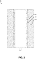
- the e-liquid storage device may include a cylindrical e-liquid storage medium 53 positioned outside of the exterior surface, as shown in FIG. 2 .
- the cylindrical e-liquid storage medium 53 may include cotton fibers, polypropylene fibers, terylene fibers, nylon fibers, porous ceramic materials, and any combinations of these materials.
- the present invention relates to an electronic cigarette having the ceramic vaporizer described above.
- the present invention relates to an electronic cigarette 10 having a ceramic vaporizer 5.
- the electronic cigarette 10 may include a mouthpiece assembly 9, an electronic cigarette body 1, a lower portion 4 of the ceramic vaporizer 5, an air adjustment assembly 8, and an electric connector assembly 6.
- the mouthpiece assembly 9 may be removed to refill e-liquid to e-liquid storage of the electronic cigarette 10.
- the electronic cigarette body 1 may include a top cover 12, and a tubular electronic cigarette body 11.
- the tubular electronic cigarette body 11 may define one or more openings to allow a user to observe level of e-liquid inside of an e-liquid storage device.
- the electronic cigarette 10 includes the ceramic vaporizer 5.
- the ceramic vaporizer 5 may include a cylindrical vaporizer body 52, and a vaporizer heater 51.
- the cylindrical vaporizer body 52 may include an interior surface, and an exterior surface. The interior surface forms a central vapor passage, and the exterior surface forms an inside wall of an e-liquid storage device.
- the vaporizer heater 51 is embedded inside the cylindrical vaporizer body.
- the vaporizer heater 51 may include one or more heating elements.
- the one or more heating elements are configured to heat e-liquid stored in the e-liquid storage device and the e-liquid is in direct contact with the surfaces of the cylindrical vaporizer body 52.
- the one or more heating elements may include Aluminum (Al), Chromium(Cr), Manganese (Mn), Iron (Fe), Cobalt (Co), Nickel (Ni), Copper (Cu), Zirconium (Zr), Niobium (Nb), Molybdenur (Mo), Rhenium (Re), Silver (Ag), Cadmium (Cd), Tantalum (Ta), Tungsten (W), Iridium (Ir), Platinum (Pt), Gold (Au), and alloys of these elements.
- the one or more heating elements may include one or more mesh heating elements, and one or more spiral heating elements.
- each of the one or more heating elements may include a first electrical input terminal configured to connect to a first terminal of a power supply of the electronic cigarette, and a second electrical input terminal configured to connect to a second terminal of the power supply of electronic cigarette.
- the electronic cigarette 10 may also include a mouthpiece assembly 9.
- the mouth piece assembly 9 may include a mouthpiece, a mouthpiece connector, and a mouthpiece sealing ring.
- the mouthpiece may include a hollow center air passage connected to the central vapor passage of the ceramic vaporizer 5.
- the hollow center air passage is configured to provide vaporized e-liquid to a user.
- the mouthpiece connector may include a threaded lower portion threadedly connected to a ceramic vaporizer body support.
- the mouthpiece sealing ring is configured to prevent the vaporized e-liquid to leak from the mouthpiece connector.
- the electronic cigarette 10 may include an air adjustment assembly 8.
- the air adjustment assembly 8 may include an air adjustment assembly base, an air adjustment ring, and a sealing ring.
- the air adjustment assembly base may include an upper tubular portion threadedly connected to a lower outside threaded portion of the ceramic vaporizer 5.
- An air adjustment chamber is defined inside of the air adjustment assembly base.
- the air adjustment chamber may include a predetermined number of first air vents provided to supply air from outside to inside of the air adjustment chamber.
- the air adjustment ring is positioned outside of the upper tubular portion of the air adjustment assembly base.
- the air adjustment ring may include a predetermined number of second air vents.
- the sealing ring is configured to prevent air leak from the air adjustment chamber.
- the electronic cigarette 10 may also include an electric connector assembly 6.
- the electric connector assembly 6 may include an electric connector base 61, an electrode 62, and an insulation cover 63, as shown in FIGs. 4 and 5 .
- the electric connector base is attached to the air adjustment assembly 8 and adapted for connecting the electric power supply to the one or more heating elements of the ceramic vaporizer 5.
- the electric connector base may include an outer thread configured to electrically connect the first terminal of the power supply of the electronic cigarette to the first electrical input terminal of the one or more heating elements.
- the electrode is configured to electrically connect the second terminal of the power supply to the second electrical input terminal of one or more heating elements.
- the insulation cover is positioned between the electric connector base and the electrode to provide insulation between the first terminal and the second terminal of the power supply of the electronic cigarette.
- the electronic cigarette 10 may also include an electric power switch configured to allow the user to turn on and off the power supply to the electronic cigarette.
- the electronic cigarette 10 may also include an electric power adjustment device.
- the electric power adjustment device may allow the user to adjust the electric power to control vaporization of the e-liquid.
- the e-liquid storage device may include an e-liquid storage tank positioned outside of the exterior surface of the ceramic vaporizer.
- the e-liquid storage device may include a cylindrical e-liquid storage medium 53 positioned outside of the exterior surface as shown in FIGs. 4 and 5 .
- the cylindrical e-liquid storage medium 53 may include cotton fibers, polypropylene fibers, terylene fibers, nylon fibers, porous ceramic materials, and any combinations of these materials.
- the ceramic vaporizer may include a cylindrical vaporizer body, and a vaporizer heater.
- the cylindrical vaporizer body has an interior surface, and an exterior surface. The interior surface forms a central vapor passage and the exterior surface forms an inside wall of an e-liquid storage device.
- the vaporizer heater is embedded inside the cylindrical vaporizer body.
- the vaporizer heater may include one or more heating elements configured to heat e-liquid stored in e-liquid storage device and e-liquid is in direct contact with surfaces of the cylindrical vaporizer body.
- the one or more heating elements may include certain electrothermal alloys.
- the one or more heating elements may include one or more mesh heating elements, and one or more spiral heating elements.
Landscapes
- Health & Medical Sciences (AREA)
- Engineering & Computer Science (AREA)
- Bioinformatics & Cheminformatics (AREA)
- Pulmonology (AREA)
- Anesthesiology (AREA)
- Biomedical Technology (AREA)
- Heart & Thoracic Surgery (AREA)
- Hematology (AREA)
- Life Sciences & Earth Sciences (AREA)
- Animal Behavior & Ethology (AREA)
- General Health & Medical Sciences (AREA)
- Public Health (AREA)
- Veterinary Medicine (AREA)
- Chemical & Material Sciences (AREA)
- Chemical Kinetics & Catalysis (AREA)
- General Chemical & Material Sciences (AREA)
- Filling Or Discharging Of Gas Storage Vessels (AREA)
- Resistance Heating (AREA)
- Catching Or Destruction (AREA)
- Table Equipment (AREA)
Abstract
Description
- The present invention generally relates to the field of electronic cigarette, and more particularly to ceramic vaporizers and electronic cigarettes having the ceramic vaporizers.
- The background description provided herein is for the purpose of generally presenting the context of the disclosure. Work of the presently named inventors, to the extent it is described in this background section, as well as aspects of the description that may not otherwise qualify as prior art at the time of filing, are neither expressly nor impliedly admitted as prior art against the present disclosure.
- It is well known that smoking cigarette is harmful to smoker's health. The active ingredient in a cigarette is mainly nicotine. During smoking, nicotine, along with tar aerosol droplets produced in the cigarette burning, are breathed into the alveolus and absorbed quickly by the smoker. Once nicotine is absorbed into the blood of the smoker, nicotine then produces its effect on the receptors of the smoker's central nervous system, causing the smoker relax and enjoy an inebriety similar to that produced by an exhilarant.
- The electronic cigarette is sometimes referred as electronic vaporing device, personal vaporizer (PV), or electronic nicotine delivery system (ENDS). It is a battery-powered device which simulates tobacco smoking. It generally uses a heating element that vaporizes a liquid solution (e-liquid). Some solutions contain a mixture of nicotine and a variety of flavorings, while others release a flavored vapor without nicotine. Many are designed to simulate smoking experience, such as cigarette smoking or cigar smoking. Some of them are made with similar appearance, while others are made considerably different in appearance.
- Conventional electronic cigarettes are made with a mouthpiece assembly, a vaporizer assembly, an electric connecting assembly, and an e-liquid storage assembly. The mouthpiece is installed on top of the e-liquid storage assembly, and the vaporizer assembly is installed inside of the e-liquid storage assembly, and electrically connected to a DC power source through the electric connecting assembly. The mouthpiece assembly is connected to the vaporizer assembly and forms an air flow passage. The e-liquid is stored in the e-liquid storage assembly. The e-liquid flows through a vaporizing chamber of the heating assembly using fiber threads. The e-liquid in the fiber threads is then heated by a heating wire of the heating assembly and therefore vaporized. The vaporized e-liquid goes up to the mouthpiece such that a smoker enjoys the vaporized e-liquid. However, when e-liquid makes direct contact with the heating element, it may cause certain burning smell that negatively impact user experiences.
- Therefore, an unaddressed need exists in the art to address the aforementioned deficiencies and inadequacies.
- In one aspect, the present invention relates to a ceramic vaporizer for electronic cigarette. In certain embodiments, the ceramic vaporizer may include a cylindrical vaporizer body, and a vaporizer heater. The cylindrical vaporizer body has an interior surface, and an exterior surface. The interior surface forms a central vapor passage and the exterior surface forms an inside wall of an e-liquid storage device. The vaporizer heater is embedded inside the cylindrical vaporizer body.
- In certain embodiments, the vaporizer heater may include one or more heating elements. The one or more heating elements are configured to heat e-liquid stored in the e-liquid storage device and the e-liquid is in direct contact with the surfaces of the cylindrical vaporizer body.
- In certain embodiments, the one or more heating elements may include: Aluminum (Al), Chromium(Cr), Manganese (Mn), Iron (Fe), Cobalt (Co), Nickel (Ni), Copper (Cu), Zirconium (Zr), Niobium (Nb), Molybdenur (Mo), Rhenium (Re), Silver (Ag), Cadmium (Cd), Tantalum (Ta), Tungsten (W), Iridium (Ir), Platinum (Pt), Gold (Au), and alloys of these elements.
- In certain embodiments, the one or more heating elements may include one or more mesh heating elements, and one or more spiral heating elements.
- In certain embodiments, each of the one or more heating elements may include a first electrical input terminal configured to connect to a first terminal of a power supply of an electronic cigarette, and a second electrical input terminal configured to connect to a second terminal of the power supply of the electronic cigarette.
- In one embodiment, the e-liquid storage device may include an e-liquid storage tank positioned outside of the exterior surface. In another embodiment, the e-liquid storage device may include a cylindrical e-liquid storage medium positioned outside of the exterior surface. The cylindrical e-liquid storage medium may include cotton fibers, polypropylene fibers, terylene fibers, nylon fibers, porous ceramic materials, and any combinations of these materials.
- In certain embodiments, the present invention relates to an electronic cigarette having the ceramic vaporizer described above.
- In another aspect, the present invention relates to an electronic cigarette having a ceramic vaporizer. In certain embodiments, the ceramic vaporizer may include a cylindrical vaporizer body, and a vaporizer heater. The cylindrical vaporizer body may include an interior surface, and an exterior surface. The interior surface forms a central vapor passage, and the exterior surface forms an inside wall of an e-liquid storage device. The vaporizer heater is embedded inside the cylindrical vaporizer body.
- In certain embodiments, the vaporizer heater may include one or more heating elements. The one or more heating elements are configured to heat e-liquid stored in the e-liquid storage device and the e-liquid is in direct contact with the surfaces of the cylindrical vaporizer body.
- In certain embodiments, the one or more heating elements may include Aluminum (Al), Chromium(Cr), Manganese (Mn), Iron (Fe), Cobalt (Co), Nickel (Ni), Copper (Cu), Zirconium (Zr), Niobium (Nb), Molybdenur (Mo), Rhenium (Re), Silver (Ag), Cadmium (Cd), Tantalum (Ta), Tungsten (W), Iridium (Ir), Platinum (Pt), Gold (Au), and alloys of these elements.
- In certain embodiments, the one or more heating elements may include one or more mesh heating elements, and one or more spiral heating elements.
- In certain embodiments, each of the one or more heating elements may include a first electrical input terminal configured to connect to a first terminal of a power supply of the electronic cigarette, and a second electrical input terminal configured to connect to a second terminal of the power supply of the electronic cigarette.
- In certain embodiments, the electronic cigarette may include an air adjustment assembly. The air adjustment assembly may include an air adjustment assembly base, an air adjustment ring, and a sealing ring. The air adjustment assembly base may include an upper tubular portion threadedly connected to a lower outside threaded portion of the ceramic vaporizer. An air adjustment chamber is defined inside of the air adjustment assembly base. The air adjustment chamber may include a predetermined number of first air vents provided to supply air from outside to inside of the air adjustment chamber. The air adjustment ring is positioned outside of the upper tubular portion of the air adjustment assembly base. The air adjustment ring may include a predetermined number of second air vents. The sealing ring is configured to prevent air leak from the air adjustment chamber.
- In certain embodiments, when a user rotates the air adjustment ring around the upper tubular portion of the air adjustment assembly base, and when the locations of the second air vents of the air adjustment ring match the locations of the first air vents, air flow from outside to the air adjustment chamber reaches maximum capacity. When the user further rotates the air adjustment ring around the upper tubular portion, the air flow decreases. When the locations of the second air vents of the air adjustment ring completely misalign with the locations of the first air vents, the air flow stops.
- In certain embodiments, the electronic cigarette may also include an electric connector assembly. The electric connector assembly may include an electric connector base, an electrode, and an insulation cover. The electric connector base is attached to the air adjustment assembly and adapted for connecting the electric power supply to the one or more heating elements of the ceramic vaporizer. The electric connector base may include an outer thread configured to electrically connect the first terminal of the power supply of the electronic cigarette to the first electrical input terminal of the one or more heating elements. The electrode is configured to electrically connect the second terminal of the power supply to the second electrical input terminal of one or more heating elements. The insulation cover is positioned between the electric connector base and the electrode to provide insulation between the first terminal and the second terminal of the power supply of the electronic cigarette.
- In one embodiment, the electronic cigarette may also include an electric power switch configured to allow the user to turn on and off the power supply to the electronic cigarette.
- In certain embodiments, the electronic cigarette may also include an electric power adjustment device. The electric power adjustment device may allow the user to adjust the electric power to control vaporization of the e-liquid.
- In certain embodiments, the e-liquid storage device may include an e-liquid storage tank positioned outside of the exterior surface of the ceramic vaporizer. In another embodiment, the e-liquid storage device may include a cylindrical e-liquid storage medium positioned outside of the exterior surface. The cylindrical e-liquid storage medium may include cotton fibers, polypropylene fibers, terylene fibers, nylon fibers, porous ceramic materials, and any combinations of these materials.
- In certain embodiments, the electronic cigarette may also include a mouthpiece assembly. The mouth piece assembly may include a mouthpiece, a mouthpiece connector, and a mouthpiece sealing ring. The mouthpiece may include a hollow center air passage connected to the central vapor passage of the ceramic vaporizer. The hollow center air passage is configured to provide vaporized e-liquid to a user. The mouthpiece connector may include a threaded lower portion threadedly connected to a ceramic vaporizer body support. The mouthpiece sealing ring is configured to prevent the vaporized e-liquid to leak from the mouthpiece connector.
- These and other aspects of the present invention will become apparent from the following description of the preferred embodiment taken in conjunction with the following drawings, although variations and modifications therein may be effected without departing from the spirit and scope of the novel concepts of the invention.
- The accompanying drawings illustrate one or more embodiments of the invention and, together with the written description, serve to explain the principles of the invention. Wherever possible, the same reference numbers are used throughout the drawings to refer to the same or like elements of an embodiment. The drawings do not limit the present invention to the specific embodiments disclosed and described herein. The drawings are not necessarily to scale, emphasis instead being placed upon clearly illustrating the principles of the invention, and wherein:
-
FIG. 1 is a cross-sectional view of a ceramic vaporizer according to certain embodiments of the present invention; -
FIG. 2 is a cross-sectional view of another ceramic vaporizer having a cylindrical e-liquid storage medium according to certain embodiments of the present invention; -
FIG. 3 is a perspective view of an electronic cigarette having a ceramic vaporizer according to certain embodiments of the present invention; -
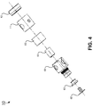
FIG. 4 is an exploded view of the electronic cigarette having the ceramic vaporizer as shown inFIG. 3 according to certain embodiments of the present invention; and -
FIG. 5 is a cross-sectional view of the electronic cigarette having the ceramic vaporizer as shown inFIG. 3 according to certain embodiments of the present invention. - The present invention will now be described more fully hereinafter with reference to the accompanying drawings, in which exemplary embodiments of the invention are shown. This invention may, however, be embodied in many different forms and should not be construed as limited to the embodiments set forth herein. Rather, these embodiments are provided so that this disclosure will be thorough and complete, and will fully convey the scope of the invention to those skilled in the art. Like reference numerals refer to like elements throughout.
- It will be understood that when an element is referred to as being "on" another element, it can be directly on the other element or intervening elements may be present therebetween. In contrast, when an element is referred to as being "directly on" another element, there are no intervening elements present. As used herein, the term "and/or" includes any and all combinations of one or more of the associated listed items.
- It will be understood that, although the terms first, second, third, etc. may be used herein to describe various elements, components, regions, layers and/or sections, these elements, components, regions, layers and/or sections should not be limited by these terms. These terms are only used to distinguish one element, component, region, layer or section from another element, component, region, layer or section. Thus, a first element, component, region, layer or section discussed below could be termed a second element, component, region, layer or section without departing from the teachings of the present invention.
- The terminology used herein is for the purpose of describing particular embodiments only and is not intended to be limiting of the invention. As used herein, the singular forms "a", "an" and "the" are intended to include the plural forms as well, unless the context clearly indicates otherwise. It will be further understood that the terms "comprises" and/or "comprising," or "includes" and/or "including" or "has" and/or "having" when used herein, specify the presence of stated features, regions, integers, steps, operations, elements, and/or components, but do not preclude the presence or addition of one or more other features, regions, integers, steps, operations, elements, components, and/or groups thereof.
- Furthermore, relative terms, such as "lower" or "bottom", "upper" or "top," and "front" or "back" may be used herein to describe one element's relationship to another element as illustrated in the Figures. It will be understood that relative terms are intended to encompass different orientations of the device in addition to the orientation depicted in the Figures. For example, if the device in one of the figures is turned over, elements described as being on the "lower" side of other elements would then be oriented on "upper" sides of the other elements. The exemplary term "lower", can therefore, encompasses both an orientation of "lower" and "upper," depending of the particular orientation of the figure. Similarly, if the device in one of the figures is turned over, elements described as "below" or "beneath" other elements would then be oriented "above" the other elements. The exemplary terms "below" or "beneath" can, therefore, encompass both an orientation of above and below.
- Unless otherwise defined, all terms (including technical and scientific terms) used herein have the same meaning as commonly understood by one of ordinary skill in the art to which this invention belongs. It will be further understood that terms, such as those defined in commonly used dictionaries, should be interpreted as having a meaning that is consistent with their meaning in the context of the relevant art and the present disclosure, and will not be interpreted in an idealized or overly formal sense unless expressly so defined herein.
- As used herein, "around", "about" or "approximately" shall generally mean within 20 percent, preferably within 10 percent, and more preferably within 5 percent of a given value or range. Numerical quantities given herein are approximates, meaning that the term "around", "about" or "approximately" can be inferred if not expressly stated.
- Many specific details are provided in the following descriptions to make the present invention be fully understood, but the present invention may also be implemented by using other manners different from those described herein, so that the present invention is not limited by the specific embodiments disclosed in the following.
- The description will be made as to the embodiments of the present invention in conjunction with the accompanying drawings
FIGs. 1 through 5 . In accordance with the purposes of this invention, as embodied and broadly described herein, this invention, in one aspect, relates to a ceramic vaporizer 5 for electronic cigarettes. - In one aspect, the present invention relates to a ceramic vaporizer 5 for electronic cigarette. Referring now to
FIG. 1 , a cross-sectional view of a ceramic vaporizer 5 is shown according to certain embodiments of the present invention. The ceramic vaporizer 5 may include acylindrical vaporizer body 52, and avaporizer heater 51. Thecylindrical vaporizer body 52 has an interior surface, and an exterior surface. The interior surface forms a central vapor passage and the exterior surface forms an inside wall of an e-liquid storage device. The ceramic vaporizer 5 is made of high quality ceramic material. It have very strong and durable surface. Thevaporizer heater 51 is embedded inside thecylindrical vaporizer body 52. In certain embodiments, thevaporizer heater 51 may include one or more heating elements. The one or more heating elements are configured to heat e-liquid stored in the e-liquid storage device and the e-liquid is in direct contact with the surfaces of thecylindrical vaporizer body 52. The e-liquid is heated through the exterior surface of the ceramic vaporizer 5. This configuration avoid direct contact between e-liquid and heating elements and it may prevent burning smell when the e-liquid makes direct contact with the heating elements. The one or more heating elements are totally covered by the ceramic material and therefore it is safe and may prevent short circuit. The ceramic vaporizer 5 is formed in much higher temperature than it is actually used in the electronic cigarette, therefore it is safe to use. The heat is transferred evenly on the surface of the ceramic vaporizer 5. On one hand, the heating elements heat the ceramic vaporizer quickly. On the other hand, the ceramic vaporizer 5 may be cooled quickly as well. The heating elements are not exposed to air so that the heating elements are prevented from oxidation. This configuration also prolongs the life of the ceramic vaporizer 5 and its heating elements. - In certain embodiments, the one or more heating elements may include: Aluminum (Al), Chromium(Cr), Manganese (Mn), Iron (Fe), Cobalt (Co), Nickel (Ni), Copper (Cu), Zirconium (Zr), Niobium (Nb), Molybdenur (Mo), Rhenium (Re), Silver (Ag), Cadmium (Cd), Tantalum (Ta), Tungsten (W), Iridium (Ir), Platinum (Pt), Gold (Au), and alloys of these elements.
- In certain embodiments, the one or more heating elements may include certain electrothermal alloys such as Nickel Chromium alloys, OCr25AL5, OCr27AL7MO2, OCr21AL6Nb, Cr15Ni60, Cr20Ni80, and Ocr19AL3 etc.
- In one embodiment, the one or more heating elements may include heating wires wounded in mesh form. In another embodiment, the one or more heating elements may include heating wires wounded in spiral form.
- In certain embodiments, each of the one or more heating elements may include a first electrical input terminal configured to connect to a first terminal of a power supply of an electronic cigarette, and a second electrical input terminal configured to connect to a second terminal of the power supply of the electronic cigarette.
- In one embodiment, the e-liquid storage device may include an e-liquid storage tank positioned outside of the exterior surface. In another embodiment, the e-liquid storage device may include a cylindrical
e-liquid storage medium 53 positioned outside of the exterior surface, as shown inFIG. 2 . The cylindricale-liquid storage medium 53 may include cotton fibers, polypropylene fibers, terylene fibers, nylon fibers, porous ceramic materials, and any combinations of these materials. - In certain embodiments, the present invention relates to an electronic cigarette having the ceramic vaporizer described above.
- In another aspect, the present invention relates to an
electronic cigarette 10 having a ceramic vaporizer 5. Referring now toFIGs. 3 ,4 , and5 , a perspective view, an exploded view and a cross-sectional view of theelectronic cigarette 10 having the ceramic vaporizer 5 are shown, respectively, according to certain embodiments of the present invention. Theelectronic cigarette 10 may include amouthpiece assembly 9, anelectronic cigarette body 1, alower portion 4 of the ceramic vaporizer 5, anair adjustment assembly 8, and anelectric connector assembly 6. In certain embodiments, themouthpiece assembly 9 may be removed to refill e-liquid to e-liquid storage of theelectronic cigarette 10. Theelectronic cigarette body 1 may include atop cover 12, and a tubularelectronic cigarette body 11. In certain embodiments, the tubularelectronic cigarette body 11 may define one or more openings to allow a user to observe level of e-liquid inside of an e-liquid storage device. - In certain embodiments, the
electronic cigarette 10 includes the ceramic vaporizer 5. The ceramic vaporizer 5 may include acylindrical vaporizer body 52, and avaporizer heater 51. Thecylindrical vaporizer body 52 may include an interior surface, and an exterior surface. The interior surface forms a central vapor passage, and the exterior surface forms an inside wall of an e-liquid storage device. Thevaporizer heater 51 is embedded inside the cylindrical vaporizer body. - In certain embodiments, the
vaporizer heater 51 may include one or more heating elements. The one or more heating elements are configured to heat e-liquid stored in the e-liquid storage device and the e-liquid is in direct contact with the surfaces of thecylindrical vaporizer body 52. - In certain embodiments, the one or more heating elements may include Aluminum (Al), Chromium(Cr), Manganese (Mn), Iron (Fe), Cobalt (Co), Nickel (Ni), Copper (Cu), Zirconium (Zr), Niobium (Nb), Molybdenur (Mo), Rhenium (Re), Silver (Ag), Cadmium (Cd), Tantalum (Ta), Tungsten (W), Iridium (Ir), Platinum (Pt), Gold (Au), and alloys of these elements.
- In certain embodiments, the one or more heating elements may include one or more mesh heating elements, and one or more spiral heating elements.
- In certain embodiments, each of the one or more heating elements may include a first electrical input terminal configured to connect to a first terminal of a power supply of the electronic cigarette, and a second electrical input terminal configured to connect to a second terminal of the power supply of electronic cigarette.
- In certain embodiments, the
electronic cigarette 10 may also include amouthpiece assembly 9. Themouth piece assembly 9 may include a mouthpiece, a mouthpiece connector, and a mouthpiece sealing ring. The mouthpiece may include a hollow center air passage connected to the central vapor passage of the ceramic vaporizer 5. The hollow center air passage is configured to provide vaporized e-liquid to a user. The mouthpiece connector may include a threaded lower portion threadedly connected to a ceramic vaporizer body support. The mouthpiece sealing ring is configured to prevent the vaporized e-liquid to leak from the mouthpiece connector. - In certain embodiments, the
electronic cigarette 10 may include anair adjustment assembly 8. Theair adjustment assembly 8 may include an air adjustment assembly base, an air adjustment ring, and a sealing ring. The air adjustment assembly base may include an upper tubular portion threadedly connected to a lower outside threaded portion of the ceramic vaporizer 5. An air adjustment chamber is defined inside of the air adjustment assembly base. The air adjustment chamber may include a predetermined number of first air vents provided to supply air from outside to inside of the air adjustment chamber. The air adjustment ring is positioned outside of the upper tubular portion of the air adjustment assembly base. The air adjustment ring may include a predetermined number of second air vents. The sealing ring is configured to prevent air leak from the air adjustment chamber. - When a user rotates the air adjustment ring around the upper tubular portion of the air adjustment assembly base, and when the locations of the second air vents of the air adjustment ring match the locations of the first air vents, air flow from outside to the air adjustment chamber reaches maximum capacity as indicated by a dashed arrow in
FIG. 5 . The air inside the air adjustment chamber may flow upwards when the user sucks air through themouthpiece assembly 9 as indicated by the upward arrow inFIG. 5 . When the air pass through the central vapor passage, the air becomes vapor and the vapor flows upward to the user through themouthpiece assembly 9. When the user further rotates the air adjustment ring around the upper tubular portion, the air flow decreases. When the locations of the second air vents of the air adjustment ring completely misalign with the locations of the first air vents, the air flow stops. - In certain embodiments, the
electronic cigarette 10 may also include anelectric connector assembly 6. Theelectric connector assembly 6 may include anelectric connector base 61, anelectrode 62, and aninsulation cover 63, as shown inFIGs. 4 and5 . The electric connector base is attached to theair adjustment assembly 8 and adapted for connecting the electric power supply to the one or more heating elements of the ceramic vaporizer 5. The electric connector base may include an outer thread configured to electrically connect the first terminal of the power supply of the electronic cigarette to the first electrical input terminal of the one or more heating elements. The electrode is configured to electrically connect the second terminal of the power supply to the second electrical input terminal of one or more heating elements. The insulation cover is positioned between the electric connector base and the electrode to provide insulation between the first terminal and the second terminal of the power supply of the electronic cigarette. - In one embodiment, the
electronic cigarette 10 may also include an electric power switch configured to allow the user to turn on and off the power supply to the electronic cigarette. - In certain embodiments, the
electronic cigarette 10 may also include an electric power adjustment device. The electric power adjustment device may allow the user to adjust the electric power to control vaporization of the e-liquid. - In certain embodiments, the e-liquid storage device may include an e-liquid storage tank positioned outside of the exterior surface of the ceramic vaporizer. In another embodiment, the e-liquid storage device may include a cylindrical
e-liquid storage medium 53 positioned outside of the exterior surface as shown inFIGs. 4 and5 . The cylindricale-liquid storage medium 53 may include cotton fibers, polypropylene fibers, terylene fibers, nylon fibers, porous ceramic materials, and any combinations of these materials. - The foregoing description of the exemplary embodiments of the invention has been presented only for the purposes of illustration and description and is not intended to be exhaustive or to limit the invention to the precise forms disclosed. Many modifications and variations are possible in light of the above teaching.
- The embodiments were chosen and described in order to explain the principles of the invention and their practical application so as to activate others skilled in the art to utilize the invention and various embodiments and with various modifications as are suited to the particular use contemplated. Alternative embodiments will become apparent to those skilled in the art to which the present invention pertains without departing from its spirit and scope. Accordingly, the scope of the present invention is defined by the appended claims, the foregoing description and the exemplary embodiments described therein, and accompanying drawings.
- Certain aspects of present invention relate to a ceramic vaporizer for electronic cigarette and electronic cigarettes having the ceramic vaporizer. In certain embodiments, the ceramic vaporizer may include a cylindrical vaporizer body, and a vaporizer heater. The cylindrical vaporizer body has an interior surface, and an exterior surface. The interior surface forms a central vapor passage and the exterior surface forms an inside wall of an e-liquid storage device. The vaporizer heater is embedded inside the cylindrical vaporizer body. The vaporizer heater may include one or more heating elements configured to heat e-liquid stored in e-liquid storage device and e-liquid is in direct contact with surfaces of the cylindrical vaporizer body. The one or more heating elements may include certain electrothermal alloys. In certain embodiments, the one or more heating elements may include one or more mesh heating elements, and one or more spiral heating elements.
Claims (14)
- A ceramic vaporizer comprising:a cylindrical vaporizer body having an interior surface, and an exterior surface, wherein the interior surface forms a central vapor passage, and the exterior surface forms an inside wall of an e-liquid storage device; anda vaporizer heater embedded inside the cylindrical vaporizer body.
- The ceramic vaporizer of claim 1, wherein the vaporizer heater comprises one or more heating elements configured to heat e-liquid in direct contact with the surfaces of the cylindrical vaporizer body.
- The ceramic vaporizer of claim 2, wherein the one or more heating elements comprise:aluminum (Al);Chromium(Cr);Manganese (Mn);Iron (Fe);Cobalt (Co);Nickel (Ni);Copper (Cu);Zirconium (Zr);Niobium (Nb);Molybdenur (Mo);Rhenium (Re);Silver (Ag);Cadmium(Cd);Tantalum (Ta);Tungsten (W);Iridium (Ir);Platinum (Pt);Gold (Au); andalloys thereof.
- The ceramic vaporizer of claim 2 or 3, wherein the one or more heating elements comprise:one or more mesh heating elements; andone or more spiral heating elements.
- The ceramic vaporizer of one of claims 2 to 4, wherein each of the one or more heating elements comprises:a first electrical input terminal configured to be connect to a first terminal of a power supply of an electronic cigarette; anda second electrical input terminal configured to connect to a second terminal of the power supply of the electronic cigarette.
- The ceramic vaporizer of one of claims 1 to 5,
wherein the e-liquid storage device comprises an e-liquid storage tank outside of the exterior surface. - The ceramic vaporizer of claim 1, wherein the e-liquid storage device comprises a cylindrical e-liquid storage medium positioned outside of the exterior surface.
- The ceramic vaporizer of claim 7, wherein the cylindrical e-liquid storage medium comprises:cotton fibers;polypropylene fibers;terylene fibers;nylon fibers;porous ceramic materials; andcombinations thereof.
- An electronic cigarette comprising the ceramic vaporizer of one of claims 1 to 8.
- The electronic cigarette of claim 9, further comprising an air adjustment assembly having:an air adjustment assembly base having an upper tubular portion threadedly connected to a lower outside threaded portion of the ceramic vaporizer, an air adjustment chamber defined inside of the air adjustment assembly base, and a plurality of first air vents;an air adjustment ring disposed outside of the upper tubular portion of the air adjustment assembly base, wherein the air adjustment ring comprises a plurality of second air vents; anda sealing ring configured to prevent air leak from the air adjustment assembly,wherein when a user rotates the air adjustment ring around the upper tubular portion of the air adjustment assembly base, and when the locations of the plurality of second air vents of the air adjustment ring match the locations of the plurality of first air vents, air flow from outside to the air adjustment chamber reaches maximum capacity, and when the user further rotates the air adjustment ring around the upper tubular portion, the air flow decreases, and when the locations of the plurality of second air vents of the air adjustment ring completely misalign with the locations of the plurality of first air vents, the air flow stops.
- The electronic cigarette of claim 10, further comprising an electric connector assembly, wherein the electric connector assembly comprises:an electric connector base attached to the air adjustment assembly and adapted for connecting the power supply to the one or more heating elements of the ceramic vaporizer, wherein the electric connector base comprises an outer thread configured to electrically connect a first terminal of the power supply of the electronic cigarette to the first electrical input terminal of the one or more heating elements;an electrode configured to electrically connect the second terminal of the power supply to the second electrical input terminal of one or more heating elements; andan insulation cover positioned between the electric connector base and the electrode to provide insulation between the first terminal and the second terminal of the power supply of the electronic cigarette.
- The electronic cigarette of claim 10 or 11, further comprising an electric power switch configured to allow the user to turn on and off the power supply to the electronic cigarette.
- The electronic cigarette of one of claims 10 to 12, further comprising an electric power adjustment device configured to allow the user to adjust the electric power to control vaporization of the e-liquid.
- The electronic cigarette of one of claims 9 to 13, further comprising a mouthpiece assembly having:a mouthpiece having a hollow center air passage connected to the central vapor passage of the ceramic vaporizer and configured to provide vaporized e-liquid to a user;a mouthpiece connector having a threaded lower portion threadedly connected to a ceramic vaporizer body support; anda mouthpiece sealing ring configured to prevent the vaporized e-liquid to leak from the mouthpiece connector.
Applications Claiming Priority (1)
| Application Number | Priority Date | Filing Date | Title |
|---|---|---|---|
| PCT/CN2016/071499 WO2017124334A1 (en) | 2016-01-20 | 2016-01-20 | Ceramic vaporizer and electronic cigarettes having the ceramic vaporizer |
Publications (3)
| Publication Number | Publication Date |
|---|---|
| EP3195738A2 true EP3195738A2 (en) | 2017-07-26 |
| EP3195738A3 EP3195738A3 (en) | 2017-08-02 |
| EP3195738B1 EP3195738B1 (en) | 2018-09-19 |
Family
ID=55353102
Family Applications (1)
| Application Number | Title | Priority Date | Filing Date |
|---|---|---|---|
| EP16155412.6A Active EP3195738B1 (en) | 2016-01-20 | 2016-02-12 | Electronic cigarette having a ceramic vaporizer |
Country Status (8)
| Country | Link |
|---|---|
| US (1) | US10834965B2 (en) |
| EP (1) | EP3195738B1 (en) |
| JP (1) | JP2018504886A (en) |
| KR (1) | KR20180040059A (en) |
| CA (1) | CA2920933C (en) |
| DK (1) | DK3195738T3 (en) |
| ES (1) | ES2691970T3 (en) |
| WO (1) | WO2017124334A1 (en) |
Cited By (22)
| Publication number | Priority date | Publication date | Assignee | Title |
|---|---|---|---|---|
| EP3216359A1 (en) * | 2016-05-27 | 2017-09-13 | Shenzhen First Union Technology Co., Ltd. | Atomizer and electronic cigarette having same |
| USD825102S1 (en) | 2016-07-28 | 2018-08-07 | Juul Labs, Inc. | Vaporizer device with cartridge |
| US10045567B2 (en) | 2013-12-23 | 2018-08-14 | Juul Labs, Inc. | Vaporization device systems and methods |
| US10045568B2 (en) | 2013-12-23 | 2018-08-14 | Juul Labs, Inc. | Vaporization device systems and methods |
| US10058130B2 (en) | 2013-12-23 | 2018-08-28 | Juul Labs, Inc. | Cartridge for use with a vaporizer device |
| US10076139B2 (en) | 2013-12-23 | 2018-09-18 | Juul Labs, Inc. | Vaporizer apparatus |
| US10104915B2 (en) | 2013-12-23 | 2018-10-23 | Juul Labs, Inc. | Securely attaching cartridges for vaporizer devices |
| US10111470B2 (en) | 2013-12-23 | 2018-10-30 | Juul Labs, Inc. | Vaporizer apparatus |
| USD836541S1 (en) | 2016-06-23 | 2018-12-25 | Pax Labs, Inc. | Charging device |
| USD842536S1 (en) | 2016-07-28 | 2019-03-05 | Juul Labs, Inc. | Vaporizer cartridge |
| US10244793B2 (en) | 2005-07-19 | 2019-04-02 | Juul Labs, Inc. | Devices for vaporization of a substance |
| US10279934B2 (en) | 2013-03-15 | 2019-05-07 | Juul Labs, Inc. | Fillable vaporizer cartridge and method of filling |
| USD849996S1 (en) | 2016-06-16 | 2019-05-28 | Pax Labs, Inc. | Vaporizer cartridge |
| USD851830S1 (en) | 2016-06-23 | 2019-06-18 | Pax Labs, Inc. | Combined vaporizer tamp and pick tool |
| US10405582B2 (en) | 2016-03-10 | 2019-09-10 | Pax Labs, Inc. | Vaporization device with lip sensing |
| US10512282B2 (en) | 2014-12-05 | 2019-12-24 | Juul Labs, Inc. | Calibrated dose control |
| WO2020048437A1 (en) * | 2018-09-03 | 2020-03-12 | 湖南中烟工业有限责任公司 | Atomizer and electronic cigarette |
| USD887632S1 (en) | 2017-09-14 | 2020-06-16 | Pax Labs, Inc. | Vaporizer cartridge |
| US10865001B2 (en) | 2016-02-11 | 2020-12-15 | Juul Labs, Inc. | Fillable vaporizer cartridge and method of filling |
| EP3965529A1 (en) * | 2020-09-07 | 2022-03-09 | Shenzhen Eigate Technology Co., Ltd. | Ceramic atomizer |
| US11369757B2 (en) | 2016-09-22 | 2022-06-28 | Juul Labs, Inc. | Leak-resistant vaporizer device |
| US11611223B2 (en) | 2018-10-19 | 2023-03-21 | Juul Labs, Inc. | Charging adapter for vaporizer device |
Families Citing this family (14)
| Publication number | Priority date | Publication date | Assignee | Title |
|---|---|---|---|---|
| US12048329B2 (en) * | 2018-09-14 | 2024-07-30 | Imperial Tobacco Limited | Consumable for a smoking substitute device |
| US11311049B2 (en) | 2018-11-20 | 2022-04-26 | Altria Client Services Llc | Air intake assembly |
| US11445759B2 (en) | 2018-11-20 | 2022-09-20 | Altria Client Services Llc | E-vaping device |
| US11304448B2 (en) | 2018-11-20 | 2022-04-19 | Altria Client Services Llc | Vaporizer assembly |
| US11071326B2 (en) | 2018-11-20 | 2021-07-27 | Altria Client Services Llc | E-vaping device |
| GB201905442D0 (en) * | 2019-04-17 | 2019-05-29 | Nicoventures Trading Ltd | Aerosol provision system |
| CN112321330B (en) * | 2019-07-31 | 2022-06-07 | 湖北中烟工业有限责任公司 | A kind of ceramic heating element based on multi-subgroup elements and its preparation method and use |
| KR102351158B1 (en) * | 2019-10-30 | 2022-01-13 | (주)인터플렉스 | Cartridge pulverizer for electronic cigarette |
| KR20210052200A (en) * | 2019-10-30 | 2021-05-10 | 주식회사 이엠텍 | Ceramic heater sturucture for microparticle generator |
| WO2021086111A1 (en) * | 2019-10-30 | 2021-05-06 | 주식회사 이엠텍 | Ceramic heater for fine particle generating device |
| CN115413243B (en) | 2019-12-23 | 2024-08-27 | Pax实验室公司 | Evaporator box |
| WO2021128115A1 (en) * | 2019-12-26 | 2021-07-01 | 丁风云 | Atomizer for electronic cigarette, and electronic cigarette |
| US11839239B2 (en) | 2020-08-12 | 2023-12-12 | DES Products Ltd. | Adjustable airflow cartridge for electronic vaporizer |
| USD1028336S1 (en) | 2021-06-22 | 2024-05-21 | Pax Labs, Inc. | Vaporizer cartridge |
Family Cites Families (17)
| Publication number | Priority date | Publication date | Assignee | Title |
|---|---|---|---|---|
| EP0845220B1 (en) * | 1996-06-17 | 2003-09-03 | Japan Tobacco Inc. | Flavor producing article |
| WO2014198157A1 (en) * | 2013-06-13 | 2014-12-18 | Shenzhen Kanger Technology Co., Ltd. | Ceramic heating elements for electronic cigarettes |
| CN202407080U (en) * | 2011-12-21 | 2012-09-05 | 深圳市五轮电子有限公司 | Electronic cigarette atomizing device |
| CN202603608U (en) * | 2012-05-17 | 2012-12-19 | 深圳市康尔科技有限公司 | Electronic cigarette |
| US9271529B2 (en) * | 2013-02-05 | 2016-03-01 | Atmos Nation Llc | Portable vaporization apparatus |
| TWI651055B (en) * | 2013-10-08 | 2019-02-21 | 傑提國際公司 | Aerosol transferring adapter for an aerosol generating device and method for transferring aerosol within an aerosol generating device |
| US20150272218A1 (en) * | 2014-03-27 | 2015-10-01 | Shenzhen Smoore Technology Limited | Electronic cigarette |
| WO2016000201A1 (en) * | 2014-07-01 | 2016-01-07 | 深圳市康尔科技有限公司 | Electronic cigarette heating assembly |
| CN106714594B (en) * | 2014-09-30 | 2019-05-17 | 惠州市吉瑞科技有限公司 | Atomizing components and electronic cigarettes |
| WO2016061859A1 (en) * | 2014-10-21 | 2016-04-28 | 朱晓春 | Heating component for electronic cigarette atomizer |
| CN204317492U (en) * | 2014-11-14 | 2015-05-13 | 深圳市合元科技有限公司 | Be applicable to atomising device and the electronic cigarette of fluid matrix |
| CN204259828U (en) * | 2014-12-17 | 2015-04-15 | 朱晓春 | Novel electronic cigarette atomizer |
| DE202015006397U1 (en) * | 2014-12-31 | 2015-12-07 | UTVG Global IP B.V. | Personal electronic delivery system |
| WO2017031472A1 (en) * | 2015-08-19 | 2017-02-23 | David Guo | Electronic cigarette/vaporizer atomizer thereof |
| CN105054308A (en) * | 2015-08-20 | 2015-11-18 | 深圳瀚星翔科技有限公司 | Heating wire assembly, atomizer and electronic cigarette |
| EP3685687B1 (en) * | 2015-10-21 | 2023-06-14 | Shenzhen Smoore Technology Limited | Electronic cigarette |
| US10092036B2 (en) * | 2015-12-28 | 2018-10-09 | Rai Strategic Holdings, Inc. | Aerosol delivery device including a housing and a coupler |
-
2016
- 2016-01-20 JP JP2016518717A patent/JP2018504886A/en active Pending
- 2016-01-20 WO PCT/CN2016/071499 patent/WO2017124334A1/en not_active Ceased
- 2016-01-20 KR KR1020167006017A patent/KR20180040059A/en not_active Ceased
- 2016-01-20 US US14/906,565 patent/US10834965B2/en active Active
- 2016-01-20 CA CA2920933A patent/CA2920933C/en active Active
- 2016-02-12 EP EP16155412.6A patent/EP3195738B1/en active Active
- 2016-02-12 ES ES16155412.6T patent/ES2691970T3/en active Active
- 2016-02-12 DK DK16155412.6T patent/DK3195738T3/en active
Non-Patent Citations (1)
| Title |
|---|
| None |
Cited By (46)
| Publication number | Priority date | Publication date | Assignee | Title |
|---|---|---|---|---|
| US10244793B2 (en) | 2005-07-19 | 2019-04-02 | Juul Labs, Inc. | Devices for vaporization of a substance |
| US10638792B2 (en) | 2013-03-15 | 2020-05-05 | Juul Labs, Inc. | Securely attaching cartridges for vaporizer devices |
| US10279934B2 (en) | 2013-03-15 | 2019-05-07 | Juul Labs, Inc. | Fillable vaporizer cartridge and method of filling |
| US10111470B2 (en) | 2013-12-23 | 2018-10-30 | Juul Labs, Inc. | Vaporizer apparatus |
| US10117465B2 (en) | 2013-12-23 | 2018-11-06 | Juul Labs, Inc. | Vaporization device systems and methods |
| US10058124B2 (en) | 2013-12-23 | 2018-08-28 | Juul Labs, Inc. | Vaporization device systems and methods |
| US10058130B2 (en) | 2013-12-23 | 2018-08-28 | Juul Labs, Inc. | Cartridge for use with a vaporizer device |
| US10070669B2 (en) | 2013-12-23 | 2018-09-11 | Juul Labs, Inc. | Cartridge for use with a vaporizer device |
| US10076139B2 (en) | 2013-12-23 | 2018-09-18 | Juul Labs, Inc. | Vaporizer apparatus |
| US10104915B2 (en) | 2013-12-23 | 2018-10-23 | Juul Labs, Inc. | Securely attaching cartridges for vaporizer devices |
| US11752283B2 (en) | 2013-12-23 | 2023-09-12 | Juul Labs, Inc. | Vaporization device systems and methods |
| US10117466B2 (en) | 2013-12-23 | 2018-11-06 | Juul Labs, Inc. | Vaporization device systems and methods |
| US10058129B2 (en) | 2013-12-23 | 2018-08-28 | Juul Labs, Inc. | Vaporization device systems and methods |
| US10159282B2 (en) | 2013-12-23 | 2018-12-25 | Juul Labs, Inc. | Cartridge for use with a vaporizer device |
| US10912331B2 (en) | 2013-12-23 | 2021-02-09 | Juul Labs, Inc. | Vaporization device systems and methods |
| US10201190B2 (en) | 2013-12-23 | 2019-02-12 | Juul Labs, Inc. | Cartridge for use with a vaporizer device |
| US10667560B2 (en) | 2013-12-23 | 2020-06-02 | Juul Labs, Inc. | Vaporizer apparatus |
| US10045568B2 (en) | 2013-12-23 | 2018-08-14 | Juul Labs, Inc. | Vaporization device systems and methods |
| US10264823B2 (en) | 2013-12-23 | 2019-04-23 | Juul Labs, Inc. | Vaporization device systems and methods |
| US10045567B2 (en) | 2013-12-23 | 2018-08-14 | Juul Labs, Inc. | Vaporization device systems and methods |
| US10701975B2 (en) | 2013-12-23 | 2020-07-07 | Juul Labs, Inc. | Vaporization device systems and methods |
| US10512282B2 (en) | 2014-12-05 | 2019-12-24 | Juul Labs, Inc. | Calibrated dose control |
| US10865001B2 (en) | 2016-02-11 | 2020-12-15 | Juul Labs, Inc. | Fillable vaporizer cartridge and method of filling |
| US10405582B2 (en) | 2016-03-10 | 2019-09-10 | Pax Labs, Inc. | Vaporization device with lip sensing |
| EP3216359A1 (en) * | 2016-05-27 | 2017-09-13 | Shenzhen First Union Technology Co., Ltd. | Atomizer and electronic cigarette having same |
| USD929036S1 (en) | 2016-06-16 | 2021-08-24 | Pax Labs, Inc. | Vaporizer cartridge and device assembly |
| USD849996S1 (en) | 2016-06-16 | 2019-05-28 | Pax Labs, Inc. | Vaporizer cartridge |
| USD913583S1 (en) | 2016-06-16 | 2021-03-16 | Pax Labs, Inc. | Vaporizer device |
| USD836541S1 (en) | 2016-06-23 | 2018-12-25 | Pax Labs, Inc. | Charging device |
| USD851830S1 (en) | 2016-06-23 | 2019-06-18 | Pax Labs, Inc. | Combined vaporizer tamp and pick tool |
| USD825102S1 (en) | 2016-07-28 | 2018-08-07 | Juul Labs, Inc. | Vaporizer device with cartridge |
| USD842536S1 (en) | 2016-07-28 | 2019-03-05 | Juul Labs, Inc. | Vaporizer cartridge |
| US11759580B2 (en) | 2016-09-22 | 2023-09-19 | Juul Labs, Inc. | Leak-resistant vaporizer device |
| US12023434B2 (en) | 2016-09-22 | 2024-07-02 | Pax Labs, Inc. | Leak-resistant vaporizer device |
| US11369757B2 (en) | 2016-09-22 | 2022-06-28 | Juul Labs, Inc. | Leak-resistant vaporizer device |
| US11369756B2 (en) | 2016-09-22 | 2022-06-28 | Juul Labs, Inc. | Leak-resistant vaporizer device |
| US11369755B2 (en) | 2016-09-22 | 2022-06-28 | Juul Labs, Inc. | Leak-resistant vaporizer device |
| US12311099B2 (en) | 2016-09-22 | 2025-05-27 | Pax Labs, Inc. | Leak-resistant vaporizer device |
| US11660403B2 (en) | 2016-09-22 | 2023-05-30 | Juul Labs, Inc. | Leak-resistant vaporizer device |
| US12226567B2 (en) | 2016-09-22 | 2025-02-18 | Pax Labs, Inc. | Leak-resistant vaporizer device |
| US11766527B2 (en) | 2016-09-22 | 2023-09-26 | Juul Labs, Inc. | Leak-resistant vaporizer device |
| USD887632S1 (en) | 2017-09-14 | 2020-06-16 | Pax Labs, Inc. | Vaporizer cartridge |
| WO2020048437A1 (en) * | 2018-09-03 | 2020-03-12 | 湖南中烟工业有限责任公司 | Atomizer and electronic cigarette |
| US11871791B2 (en) | 2018-09-03 | 2024-01-16 | China Tobacco Hunan Industrial Co., Ltd. | Atomizer and electronic cigarette with an air input amount adjustable by rotating a mouthpiece |
| US11611223B2 (en) | 2018-10-19 | 2023-03-21 | Juul Labs, Inc. | Charging adapter for vaporizer device |
| EP3965529A1 (en) * | 2020-09-07 | 2022-03-09 | Shenzhen Eigate Technology Co., Ltd. | Ceramic atomizer |
Also Published As
| Publication number | Publication date |
|---|---|
| CA2920933C (en) | 2020-03-24 |
| WO2017124334A1 (en) | 2017-07-27 |
| JP2018504886A (en) | 2018-02-22 |
| DK3195738T3 (en) | 2018-11-05 |
| US10834965B2 (en) | 2020-11-17 |
| EP3195738B1 (en) | 2018-09-19 |
| US20180310615A1 (en) | 2018-11-01 |
| EP3195738A3 (en) | 2017-08-02 |
| CA2920933A1 (en) | 2017-07-20 |
| KR20180040059A (en) | 2018-04-19 |
| ES2691970T3 (en) | 2018-11-29 |
Similar Documents
| Publication | Publication Date | Title |
|---|---|---|
| US10834965B2 (en) | Ceramic vaporizer and electronic cigarettes having the ceramic vaporizer | |
| CA2920973C (en) | Ceramic vaporizer with replaceable e-liquid storage medium and electronic cigarettes having the same | |
| KR102625040B1 (en) | Non-combustible smoking devices and their elements | |
| US9795168B2 (en) | Heating assemblies for E-cigarette vaporizers | |
| JP7175893B2 (en) | Non-combustible smoking systems, devices and elements thereof | |
| US9861134B2 (en) | Heating assembly for electronic cigarette vaporizer | |
| US9980517B2 (en) | Top refillable electronic cigarettes | |
| US20160157522A1 (en) | Vaporizer and electronic cigarettes having the vaporizer | |
| US9883699B2 (en) | Heating element for replaceable vaporizer assembly and electronic cigarettes | |
| EP3031339A1 (en) | Top refillable electronic cigarettes | |
| US11583002B2 (en) | Electronic cigarettes having vaporizers with U shaped air path and methods of using the same | |
| KR102661609B1 (en) | Non-combustible smoking device and its elements | |
| US20200196676A1 (en) | Heating elements and dual-use electronic cigarettes having the heating elements | |
| US20190000143A1 (en) | Vertical millipore vaporizer assembly and electronic cigarettes having the same | |
| US10757979B2 (en) | Electromagnetic vaporizer and electronic cigarettes having the same | |
| US20190006866A1 (en) | Millipore vaporizer assembly and electronic cigarettes having the same | |
| US9826781B1 (en) | E-liquid flow control mechanism and electronic cigarette having the same | |
| US20170367405A1 (en) | Connector having multiple threads and electronic cigarettes having the connector |
Legal Events
| Date | Code | Title | Description |
|---|---|---|---|
| PUAI | Public reference made under article 153(3) epc to a published international application that has entered the european phase |
Free format text: ORIGINAL CODE: 0009012 |
|
| STAA | Information on the status of an ep patent application or granted ep patent |
Free format text: STATUS: REQUEST FOR EXAMINATION WAS MADE |
|
| PUAL | Search report despatched |
Free format text: ORIGINAL CODE: 0009013 |
|
| 17P | Request for examination filed |
Effective date: 20160212 |
|
| AK | Designated contracting states |
Kind code of ref document: A2 Designated state(s): AL AT BE BG CH CY CZ DE DK EE ES FI FR GB GR HR HU IE IS IT LI LT LU LV MC MK MT NL NO PL PT RO RS SE SI SK SM TR |
|
| AX | Request for extension of the european patent |
Extension state: BA ME |
|
| AK | Designated contracting states |
Kind code of ref document: A3 Designated state(s): AL AT BE BG CH CY CZ DE DK EE ES FI FR GB GR HR HU IE IS IT LI LT LU LV MC MK MT NL NO PL PT RO RS SE SI SK SM TR |
|
| AX | Request for extension of the european patent |
Extension state: BA ME |
|
| RIC1 | Information provided on ipc code assigned before grant |
Ipc: A24F 47/00 20060101AFI20170627BHEP |
|
| GRAP | Despatch of communication of intention to grant a patent |
Free format text: ORIGINAL CODE: EPIDOSNIGR1 |
|
| STAA | Information on the status of an ep patent application or granted ep patent |
Free format text: STATUS: GRANT OF PATENT IS INTENDED |
|
| INTG | Intention to grant announced |
Effective date: 20180420 |
|
| GRAS | Grant fee paid |
Free format text: ORIGINAL CODE: EPIDOSNIGR3 |
|
| GRAA | (expected) grant |
Free format text: ORIGINAL CODE: 0009210 |
|
| STAA | Information on the status of an ep patent application or granted ep patent |
Free format text: STATUS: THE PATENT HAS BEEN GRANTED |
|
| AK | Designated contracting states |
Kind code of ref document: B1 Designated state(s): AL AT BE BG CH CY CZ DE DK EE ES FI FR GB GR HR HU IE IS IT LI LT LU LV MC MK MT NL NO PL PT RO RS SE SI SK SM TR |
|
| REG | Reference to a national code |
Ref country code: GB Ref legal event code: FG4D |
|
| REG | Reference to a national code |
Ref country code: CH Ref legal event code: NV Representative=s name: BOVARD AG PATENT- UND MARKENANWAELTE, CH Ref country code: CH Ref legal event code: EP |
|
| REG | Reference to a national code |
Ref country code: AT Ref legal event code: REF Ref document number: 1042235 Country of ref document: AT Kind code of ref document: T Effective date: 20181015 |
|
| REG | Reference to a national code |
Ref country code: IE Ref legal event code: FG4D |
|
| REG | Reference to a national code |
Ref country code: DE Ref legal event code: R096 Ref document number: 602016005617 Country of ref document: DE |
|
| REG | Reference to a national code |
Ref country code: NL Ref legal event code: FP |
|
| REG | Reference to a national code |
Ref country code: DK Ref legal event code: T3 Effective date: 20181022 |
|
| REG | Reference to a national code |
Ref country code: ES Ref legal event code: FG2A Ref document number: 2691970 Country of ref document: ES Kind code of ref document: T3 Effective date: 20181129 |
|
| PG25 | Lapsed in a contracting state [announced via postgrant information from national office to epo] |
Ref country code: SE Free format text: LAPSE BECAUSE OF FAILURE TO SUBMIT A TRANSLATION OF THE DESCRIPTION OR TO PAY THE FEE WITHIN THE PRESCRIBED TIME-LIMIT Effective date: 20180919 Ref country code: FI Free format text: LAPSE BECAUSE OF FAILURE TO SUBMIT A TRANSLATION OF THE DESCRIPTION OR TO PAY THE FEE WITHIN THE PRESCRIBED TIME-LIMIT Effective date: 20180919 Ref country code: NO Free format text: LAPSE BECAUSE OF FAILURE TO SUBMIT A TRANSLATION OF THE DESCRIPTION OR TO PAY THE FEE WITHIN THE PRESCRIBED TIME-LIMIT Effective date: 20181219 Ref country code: LT Free format text: LAPSE BECAUSE OF FAILURE TO SUBMIT A TRANSLATION OF THE DESCRIPTION OR TO PAY THE FEE WITHIN THE PRESCRIBED TIME-LIMIT Effective date: 20180919 Ref country code: RS Free format text: LAPSE BECAUSE OF FAILURE TO SUBMIT A TRANSLATION OF THE DESCRIPTION OR TO PAY THE FEE WITHIN THE PRESCRIBED TIME-LIMIT Effective date: 20180919 Ref country code: BG Free format text: LAPSE BECAUSE OF FAILURE TO SUBMIT A TRANSLATION OF THE DESCRIPTION OR TO PAY THE FEE WITHIN THE PRESCRIBED TIME-LIMIT Effective date: 20181219 Ref country code: GR Free format text: LAPSE BECAUSE OF FAILURE TO SUBMIT A TRANSLATION OF THE DESCRIPTION OR TO PAY THE FEE WITHIN THE PRESCRIBED TIME-LIMIT Effective date: 20181220 |
|
| REG | Reference to a national code |
Ref country code: LT Ref legal event code: MG4D |
|
| PG25 | Lapsed in a contracting state [announced via postgrant information from national office to epo] |
Ref country code: HR Free format text: LAPSE BECAUSE OF FAILURE TO SUBMIT A TRANSLATION OF THE DESCRIPTION OR TO PAY THE FEE WITHIN THE PRESCRIBED TIME-LIMIT Effective date: 20180919 Ref country code: AL Free format text: LAPSE BECAUSE OF FAILURE TO SUBMIT A TRANSLATION OF THE DESCRIPTION OR TO PAY THE FEE WITHIN THE PRESCRIBED TIME-LIMIT Effective date: 20180919 Ref country code: LV Free format text: LAPSE BECAUSE OF FAILURE TO SUBMIT A TRANSLATION OF THE DESCRIPTION OR TO PAY THE FEE WITHIN THE PRESCRIBED TIME-LIMIT Effective date: 20180919 |
|
| REG | Reference to a national code |
Ref country code: AT Ref legal event code: MK05 Ref document number: 1042235 Country of ref document: AT Kind code of ref document: T Effective date: 20180919 |
|
| PG25 | Lapsed in a contracting state [announced via postgrant information from national office to epo] |
Ref country code: CZ Free format text: LAPSE BECAUSE OF FAILURE TO SUBMIT A TRANSLATION OF THE DESCRIPTION OR TO PAY THE FEE WITHIN THE PRESCRIBED TIME-LIMIT Effective date: 20180919 Ref country code: RO Free format text: LAPSE BECAUSE OF FAILURE TO SUBMIT A TRANSLATION OF THE DESCRIPTION OR TO PAY THE FEE WITHIN THE PRESCRIBED TIME-LIMIT Effective date: 20180919 Ref country code: PL Free format text: LAPSE BECAUSE OF FAILURE TO SUBMIT A TRANSLATION OF THE DESCRIPTION OR TO PAY THE FEE WITHIN THE PRESCRIBED TIME-LIMIT Effective date: 20180919 Ref country code: EE Free format text: LAPSE BECAUSE OF FAILURE TO SUBMIT A TRANSLATION OF THE DESCRIPTION OR TO PAY THE FEE WITHIN THE PRESCRIBED TIME-LIMIT Effective date: 20180919 Ref country code: IS Free format text: LAPSE BECAUSE OF FAILURE TO SUBMIT A TRANSLATION OF THE DESCRIPTION OR TO PAY THE FEE WITHIN THE PRESCRIBED TIME-LIMIT Effective date: 20190119 Ref country code: AT Free format text: LAPSE BECAUSE OF FAILURE TO SUBMIT A TRANSLATION OF THE DESCRIPTION OR TO PAY THE FEE WITHIN THE PRESCRIBED TIME-LIMIT Effective date: 20180919 |
|
| PG25 | Lapsed in a contracting state [announced via postgrant information from national office to epo] |
Ref country code: SK Free format text: LAPSE BECAUSE OF FAILURE TO SUBMIT A TRANSLATION OF THE DESCRIPTION OR TO PAY THE FEE WITHIN THE PRESCRIBED TIME-LIMIT Effective date: 20180919 Ref country code: SM Free format text: LAPSE BECAUSE OF FAILURE TO SUBMIT A TRANSLATION OF THE DESCRIPTION OR TO PAY THE FEE WITHIN THE PRESCRIBED TIME-LIMIT Effective date: 20180919 Ref country code: PT Free format text: LAPSE BECAUSE OF FAILURE TO SUBMIT A TRANSLATION OF THE DESCRIPTION OR TO PAY THE FEE WITHIN THE PRESCRIBED TIME-LIMIT Effective date: 20190119 |
|
| REG | Reference to a national code |
Ref country code: DE Ref legal event code: R097 Ref document number: 602016005617 Country of ref document: DE |
|
| PLBE | No opposition filed within time limit |
Free format text: ORIGINAL CODE: 0009261 |
|
| STAA | Information on the status of an ep patent application or granted ep patent |
Free format text: STATUS: NO OPPOSITION FILED WITHIN TIME LIMIT |
|
| 26N | No opposition filed |
Effective date: 20190620 |
|
| PG25 | Lapsed in a contracting state [announced via postgrant information from national office to epo] |
Ref country code: LU Free format text: LAPSE BECAUSE OF NON-PAYMENT OF DUE FEES Effective date: 20190212 Ref country code: MC Free format text: LAPSE BECAUSE OF FAILURE TO SUBMIT A TRANSLATION OF THE DESCRIPTION OR TO PAY THE FEE WITHIN THE PRESCRIBED TIME-LIMIT Effective date: 20180919 Ref country code: SI Free format text: LAPSE BECAUSE OF FAILURE TO SUBMIT A TRANSLATION OF THE DESCRIPTION OR TO PAY THE FEE WITHIN THE PRESCRIBED TIME-LIMIT Effective date: 20180919 |
|
| PGFP | Annual fee paid to national office [announced via postgrant information from national office to epo] |
Ref country code: ES Payment date: 20200322 Year of fee payment: 5 Ref country code: NL Payment date: 20200219 Year of fee payment: 5 Ref country code: DK Payment date: 20200224 Year of fee payment: 5 Ref country code: DE Payment date: 20191115 Year of fee payment: 5 Ref country code: IE Payment date: 20200219 Year of fee payment: 5 Ref country code: IT Payment date: 20200225 Year of fee payment: 5 |
|
| PGFP | Annual fee paid to national office [announced via postgrant information from national office to epo] |
Ref country code: BE Payment date: 20200219 Year of fee payment: 5 Ref country code: CH Payment date: 20200219 Year of fee payment: 5 |
|
| PG25 | Lapsed in a contracting state [announced via postgrant information from national office to epo] |
Ref country code: MT Free format text: LAPSE BECAUSE OF NON-PAYMENT OF DUE FEES Effective date: 20190212 |
|
| PGFP | Annual fee paid to national office [announced via postgrant information from national office to epo] |
Ref country code: TR Payment date: 20200212 Year of fee payment: 5 Ref country code: FR Payment date: 20200219 Year of fee payment: 5 |
|
| PG25 | Lapsed in a contracting state [announced via postgrant information from national office to epo] |
Ref country code: CY Free format text: LAPSE BECAUSE OF FAILURE TO SUBMIT A TRANSLATION OF THE DESCRIPTION OR TO PAY THE FEE WITHIN THE PRESCRIBED TIME-LIMIT Effective date: 20180919 |
|
| PG25 | Lapsed in a contracting state [announced via postgrant information from national office to epo] |
Ref country code: HU Free format text: LAPSE BECAUSE OF FAILURE TO SUBMIT A TRANSLATION OF THE DESCRIPTION OR TO PAY THE FEE WITHIN THE PRESCRIBED TIME-LIMIT; INVALID AB INITIO Effective date: 20160212 |
|
| REG | Reference to a national code |
Ref country code: DE Ref legal event code: R119 Ref document number: 602016005617 Country of ref document: DE |
|
| REG | Reference to a national code |
Ref country code: DK Ref legal event code: EBP Effective date: 20210228 |
|
| REG | Reference to a national code |
Ref country code: BE Ref legal event code: MM Effective date: 20210228 |
|
| PG25 | Lapsed in a contracting state [announced via postgrant information from national office to epo] |
Ref country code: LI Free format text: LAPSE BECAUSE OF NON-PAYMENT OF DUE FEES Effective date: 20210228 Ref country code: CH Free format text: LAPSE BECAUSE OF NON-PAYMENT OF DUE FEES Effective date: 20210228 |
|
| REG | Reference to a national code |
Ref country code: NL Ref legal event code: MM Effective date: 20210301 |
|
| PG25 | Lapsed in a contracting state [announced via postgrant information from national office to epo] |
Ref country code: NL Free format text: LAPSE BECAUSE OF NON-PAYMENT OF DUE FEES Effective date: 20210301 |
|
| PG25 | Lapsed in a contracting state [announced via postgrant information from national office to epo] |
Ref country code: IE Free format text: LAPSE BECAUSE OF NON-PAYMENT OF DUE FEES Effective date: 20210212 Ref country code: FR Free format text: LAPSE BECAUSE OF NON-PAYMENT OF DUE FEES Effective date: 20210228 Ref country code: DK Free format text: LAPSE BECAUSE OF NON-PAYMENT OF DUE FEES Effective date: 20210228 Ref country code: DE Free format text: LAPSE BECAUSE OF NON-PAYMENT OF DUE FEES Effective date: 20210901 |
|
| PG25 | Lapsed in a contracting state [announced via postgrant information from national office to epo] |
Ref country code: IT Free format text: LAPSE BECAUSE OF NON-PAYMENT OF DUE FEES Effective date: 20210212 |
|
| PGFP | Annual fee paid to national office [announced via postgrant information from national office to epo] |
Ref country code: GB Payment date: 20220221 Year of fee payment: 7 |
|
| REG | Reference to a national code |
Ref country code: ES Ref legal event code: FD2A Effective date: 20220510 |
|
| PG25 | Lapsed in a contracting state [announced via postgrant information from national office to epo] |
Ref country code: MK Free format text: LAPSE BECAUSE OF FAILURE TO SUBMIT A TRANSLATION OF THE DESCRIPTION OR TO PAY THE FEE WITHIN THE PRESCRIBED TIME-LIMIT Effective date: 20180919 |
|
| PG25 | Lapsed in a contracting state [announced via postgrant information from national office to epo] |
Ref country code: ES Free format text: LAPSE BECAUSE OF NON-PAYMENT OF DUE FEES Effective date: 20210213 Ref country code: BE Free format text: LAPSE BECAUSE OF NON-PAYMENT OF DUE FEES Effective date: 20210228 |
|
| GBPC | Gb: european patent ceased through non-payment of renewal fee |
Effective date: 20230212 |
|
| PG25 | Lapsed in a contracting state [announced via postgrant information from national office to epo] |
Ref country code: GB Free format text: LAPSE BECAUSE OF NON-PAYMENT OF DUE FEES Effective date: 20230212 |
|
| PG25 | Lapsed in a contracting state [announced via postgrant information from national office to epo] |
Ref country code: GB Free format text: LAPSE BECAUSE OF NON-PAYMENT OF DUE FEES Effective date: 20230212 |