EP3195585B1 - Enablement and disablement of cameras - Google Patents
Enablement and disablement of cameras Download PDFInfo
- Publication number
- EP3195585B1 EP3195585B1 EP14900877.3A EP14900877A EP3195585B1 EP 3195585 B1 EP3195585 B1 EP 3195585B1 EP 14900877 A EP14900877 A EP 14900877A EP 3195585 B1 EP3195585 B1 EP 3195585B1
- Authority
- EP
- European Patent Office
- Prior art keywords
- camera
- button
- disable
- enable
- state
- Prior art date
- Legal status (The legal status is an assumption and is not a legal conclusion. Google has not performed a legal analysis and makes no representation as to the accuracy of the status listed.)
- Active
Links
Images



Classifications
-
- H—ELECTRICITY
- H04—ELECTRIC COMMUNICATION TECHNIQUE
- H04N—PICTORIAL COMMUNICATION, e.g. TELEVISION
- H04N23/00—Cameras or camera modules comprising electronic image sensors; Control thereof
- H04N23/60—Control of cameras or camera modules
- H04N23/62—Control of parameters via user interfaces
-
- H—ELECTRICITY
- H04—ELECTRIC COMMUNICATION TECHNIQUE
- H04N—PICTORIAL COMMUNICATION, e.g. TELEVISION
- H04N5/00—Details of television systems
- H04N5/76—Television signal recording
- H04N5/765—Interface circuits between an apparatus for recording and another apparatus
- H04N5/77—Interface circuits between an apparatus for recording and another apparatus between a recording apparatus and a television camera
-
- G—PHYSICS
- G06—COMPUTING OR CALCULATING; COUNTING
- G06F—ELECTRIC DIGITAL DATA PROCESSING
- G06F21/00—Security arrangements for protecting computers, components thereof, programs or data against unauthorised activity
- G06F21/50—Monitoring users, programs or devices to maintain the integrity of platforms, e.g. of processors, firmware or operating systems
- G06F21/57—Certifying or maintaining trusted computer platforms, e.g. secure boots or power-downs, version controls, system software checks, secure updates or assessing vulnerabilities
- G06F21/572—Secure firmware programming, e.g. of basic input output system [BIOS]
-
- G—PHYSICS
- G06—COMPUTING OR CALCULATING; COUNTING
- G06F—ELECTRIC DIGITAL DATA PROCESSING
- G06F21/00—Security arrangements for protecting computers, components thereof, programs or data against unauthorised activity
- G06F21/50—Monitoring users, programs or devices to maintain the integrity of platforms, e.g. of processors, firmware or operating systems
- G06F21/57—Certifying or maintaining trusted computer platforms, e.g. secure boots or power-downs, version controls, system software checks, secure updates or assessing vulnerabilities
- G06F21/575—Secure boot
-
- G—PHYSICS
- G06—COMPUTING OR CALCULATING; COUNTING
- G06F—ELECTRIC DIGITAL DATA PROCESSING
- G06F21/00—Security arrangements for protecting computers, components thereof, programs or data against unauthorised activity
- G06F21/60—Protecting data
- G06F21/62—Protecting access to data via a platform, e.g. using keys or access control rules
- G06F21/629—Protecting access to data via a platform, e.g. using keys or access control rules to features or functions of an application
-
- G—PHYSICS
- G06—COMPUTING OR CALCULATING; COUNTING
- G06F—ELECTRIC DIGITAL DATA PROCESSING
- G06F21/00—Security arrangements for protecting computers, components thereof, programs or data against unauthorised activity
- G06F21/70—Protecting specific internal or peripheral components, in which the protection of a component leads to protection of the entire computer
-
- G—PHYSICS
- G06—COMPUTING OR CALCULATING; COUNTING
- G06F—ELECTRIC DIGITAL DATA PROCESSING
- G06F21/00—Security arrangements for protecting computers, components thereof, programs or data against unauthorised activity
- G06F21/70—Protecting specific internal or peripheral components, in which the protection of a component leads to protection of the entire computer
- G06F21/82—Protecting input, output or interconnection devices
-
- G—PHYSICS
- G06—COMPUTING OR CALCULATING; COUNTING
- G06F—ELECTRIC DIGITAL DATA PROCESSING
- G06F9/00—Arrangements for program control, e.g. control units
- G06F9/06—Arrangements for program control, e.g. control units using stored programs, i.e. using an internal store of processing equipment to receive or retain programs
- G06F9/44—Arrangements for executing specific programs
- G06F9/4401—Bootstrapping
-
- H—ELECTRICITY
- H04—ELECTRIC COMMUNICATION TECHNIQUE
- H04N—PICTORIAL COMMUNICATION, e.g. TELEVISION
- H04N23/00—Cameras or camera modules comprising electronic image sensors; Control thereof
-
- H—ELECTRICITY
- H04—ELECTRIC COMMUNICATION TECHNIQUE
- H04N—PICTORIAL COMMUNICATION, e.g. TELEVISION
- H04N23/00—Cameras or camera modules comprising electronic image sensors; Control thereof
- H04N23/60—Control of cameras or camera modules
- H04N23/65—Control of camera operation in relation to power supply
Definitions
- US 2010/191947 A1 discloses a mobile terminal having a BIOS setup procedure allowing a user to enable or disable devices of the mobile terminal.
- US 2011/016335 A1 discloses a power switch mechanism for manual switching of the power supply status of a camera, to assure user control of the power supply status.
- US 2005/068423 A1 discloses a computer provided with a privacy lens cover.
- Electronic devices may include a camera that records images (still and/or video). User of such electronic devices may utilize these images with applications such as, for example, video conferencing, email, and instant messaging. Unfortunately, however, hackers or other unauthorized persons may enable the camera on such an electronic device without a user's knowledge or permission. If this occurs, the camera may be utilized by such hackers or other unauthorized persons to record images of the end user and/or the location (e.g., home, office, car, etc.) in which the end user is utilizing the electronic device. These recorded images may be used, transmitted, forwarded., sent, distributed and/or displayed without the user's knowledge or permission. This may cause security, privacy and/or other concerns for at least some of the users of such electronic devices.
- One way in which a camera of an electronic device may be disabled is to utilize a moveable door or other cover that blocks light from entering the lens of the camera to prevent recordation of images.
- One potential issue with such moveable doors or covers is that they may require an electronic device to have a certain minimum thickness. This minimum thickness may prevent utilization of such moveable doors or covers in at least some electronic devices that are designed to be thin such as, for example, some tablets and phones.
- Moveable doors or covers may also add to the overall cost of an electronic device which, at least some end users may not be able to afford or be willing to pay.
- Another way in which a camera of an electronic device may be disabled is to utilize opaque tape to block light from entering the lens of the camera to prevent recordation of images.
- opaque tape One potential issue with such opaque tape, however, is that, when removed, it may leave a residue on the lens of the camera which may degrade the quality (e.g., sharpness, contrast, color, etc.) of the images recorded by the camera.
- Another potential issue with such opaque tape is that it may not be readily available to an end user when he or she wants to disable the camera of his or her electronic device.
- An additional potential issue with such opaque tape is that it may inadvertently be placed over other components of an electronic device such as, for example, a microphone or speaker, thereby interfering with the operation of an electronic device.
- An additional way in which a camera of an electronic device may be disabled is to utilize a driver (e.g., machine-readable instructions) of the camera to disable the camera to prevent recordation of images.
- a driver e.g., machine-readable instructions
- a potential issue with the use of such camera driver to disable the camera is that such camera driver can be hacked or otherwise compromised to enable the camera on such an electronic device without a user's knowledge or permission.
- Example implementations directed to securely disabling, as well as enabling, a camera of an electronic device are shown in FIGs. 1 ⁇ 10 . These example implementations illustrated in FIGs. 1 ⁇ 10 also attempt to address the above-described potential technical challenges associated with other possible approaches to disable the camera of an electronic device.
- the term “electronic device” represents, but is not necessarily limited to, a computer, server, tablet, monitor, phone, personal digital assistant, kiosk, television, display, or combination thereof.
- the term “camera” represent, but is not necessarily limited to, a device that records images, still and/or video, by utilizing a lens assembly, shutter, associated electronics, and a photosensitive member or film. Examples of a photosensitive member include, but are not limited to, a charge-coupled device (CCD) or a complementary metal-oxide semiconductor (CMOS).
- CCD charge-coupled device
- CMOS complementary metal-oxide semiconductor
- processor represents, but is not necessarily limited to, an instruction execution system such as a computer-based system, an application specific integrated circuit (ASIC), a computing device, a hardware and/or machine-readable instruction system, or any combination thereof, that can fetch or obtain the logic from a machine-readable non-transitory storage medium and execute the instructions contained thereon.
- ASIC application specific integrated circuit
- processor can also include any controller, state-machine, microprocessor, logic control circuitry, cloud-based utility, service or feature, any other analogue, digital and/or mechanical implementation thereof, or any combination of the forgoing.
- a processor may be a component of a distributed system.
- the term “distributed system” represents, but is not necessarily limited to, multiple processors and machine-readable non-transitory storage media in different locations or systems that communicate via a network, such as the cloud.
- the term “cloud” represents, but is not necessarily limited to, computing resources (hardware and/or machine readable instructions) that are delivered as a service over a networlk (such as the internet),
- machine-readable non-transitory storage medium represents, but is not necessarily limited to, any medium that can contain, store, retain, or maintain programs, code scripts, information, and/or data.
- a machine-readable non-transitory storage medium may include any one of many physical media such as, for example, electronic, magnetic, optical, electromagnetic, or semiconductor media.
- a machine-readable non-transitory storage medium may be a component of a distributed system.
- suitable machine-readable non-transitory storage media include, but are not limited to, a magnetic computer diskette such as floppy diskettes or hard drives, magnetic tape, a read-only memory (ROM), an erasable programmable read-only memory (EPROM), a flash drive or memory, a compact disc (CD), a digital video disk (DVD), or a memristor.
- a magnetic computer diskette such as floppy diskettes or hard drives
- magnetic tape such as floppy diskettes or hard drives
- ROM read-only memory
- EPROM erasable programmable read-only memory
- flash drive or memory such as compact disc (CD), a digital video disk (DVD), or a memristor.
- CD compact disc
- DVD digital video disk
- memristor memristor
- BIOS basic input and output system
- BIOS basic input and output system
- persistent memory e.g ., ROM. EPROM, flash drive, etc.
- the term “button” represents, but is not necessarily limited to, a mechanical, electrical, or electromechanical device that is actuable between at least two positions, states, or conditions. Examples of a button include, but are not necessarily limited to, a capacitive sensor, a pushbutton, a key, a photodiode, a proximity sensor, and an inductive sensor.
- the term "input device” represents, but is not necessarily limited to, a peripheral and any related driver or machine readable instructions used to provide data and/or control signals to an electronic device and/or components (e.g., a camera) thereof.
- Examples of an input device include, but are not limited to, a keyboard, keypad, mouse, pointer, trackball, or joystick.
- apparatus 10 may be part of an electronic device (not shown in FIG. 1 ). Apparatus 10 may be utilized to securely enable and disable a camera, as provided herein.
- apparatus 10 includes a camera 12 to record an image and a basic input and output system engine 14 coupled to camera 12, for example by a Universal Serial Bus (USB) interface, as generally indicated by arrow 16.
- Basic input and output system engine 14 includes a first state to enable camera 12 to record an image, a second state to disable camera 12, and a third state that allows camera 12 to be enabled and disabled indpendent of basic input and output system engine 14.
- Basic input and output system engine 14 may represent any circuitry, processor, executable instructions, application programming interfaces (APIs), machine-readable non-transitory storage medium, or any combination thereof, that provides the above-described first, second, and third states.
- APIs application programming interfaces
- apparatus 10 also includes a button 18 coupled to basic input and output system engine 14, as generally indicated by arrow 20.
- Button 18 is actuable between an on condition to enable camera 12 to record an image when basic input and output system engine 14 is in the third state and an off condition to disable camera 12 when basic input and output system engine 14 is in the third state.
- One way in which button 18 may disable camera 12 in the off condition is to remove power to camera 12. It should be noted, that in this example of apparatus 10, button 18 has no effect on camera 12 when basic input and output system engine 14 is in either the first or second states.
- This feature of basic input and output system engine 14 provides a first high level of security to disable camera 10 that helps to prevent hacking to enable camera 10.
- This feature of basic input and output system engine 14 also provides a first high level of security to enable camera 10 that helps to prevent hacking to disable camera 10.
- apparatus 10 also includes an input device 22 both to selectively enable camera 12 to record an image when button 18 is in the on condition and disable camera 12 when button 18 is in the on condition.
- This selectivity may be provided, for example, by allowing a user to choose to enable or disable camera 12 via input device 22.
- input device 22 has no effect on camera 12 when button 18 is in the off condition.
- This feature of button 18 provides a second level of security to disable camera 10 that helps to prevent hacking of to enable camera 10.
- a third level of security is also provided by input device 22 itself which can selectively enable and disable camera 12.
- apparatus 10 may also include a controller 26 to securely enable and disable camera 12.
- Controller 26 is coupled to camera 12, as generally indicated by arrow 28, and to basic input and output system engine 14, as generally indicated by arrow 30.
- controller 26 is also coupled to button 18 and to input device 22.
- Controller 26 may include, for example, a Super I/O controller, a Southbridge controller, or other type of embedded controller and may be coupled to camera 12, for example, via a secure General Purpose Input/Output (GPIO) interface.
- GPIO General Purpose Input/Output
- apparatus 10 may include an indicator 32 coupled to camera 12, as generally indicated by arrow 34, to signify whether camera 12 is enabled or disabled.
- Indicator 32 may include, for example, a light source, a buzzer, a multicolored light emitting diode (LED), or multiple different colored LEDs.
- apparatus 10 may additionally include a computer 36 that is coupled to Basic Input and Output System Engine 14, as generally indicated by double-headed arrow 38.
- apparatus 10 may additionally include a processor 40 and a machine-readable non-transitory storage medium 42 including instructions executable by processor 40, as generally indicated by double-headed arrow 44, to disable camera 12 via button 18, as generally indicated by arrow 46, and/or to disable camera 12 via input device 22, as generally indicater by arrow 48.
- Non-transitory storage medium 42 may also include additional instructions exucutable by processor 12 to enable camera 12 via button 18 and/or input device 22.
- Processor 40 and non-transitory storage medium 42 may be components of an electronic device 50.
- basic input and output system engine 14 of apparatus 10 may include a processor 52 and a machine-readable non-transitory storage medium 54 including instructions executable by processor 52, as generally indicated by double-headed arrow 56, to enable camera 12 and todisable camera 12.
- Machine-readable non-transitory storage medium 54 also includes instructions executable by processor 52 to allow camera 12 to be enabled and disabled by, for example, button 18 and input device 22 when basic input and output system engine 14 is in the third state, as discussed above.
- Method 58 may be utilized to securely enable and disable a camera, as provided herein.
- method 58 may be utilized in apparatus 10.
- method 58 starts or begins 60 by providing a first state to enable a camera to record an image, as indicated by block 62, providing a second state to disable the camera, as indicated by block 64, and providing a third state to permit the camera to be enabled and disabled, as indicated by block 66.
- Blocks 62, 64, and 66 may be for example, by a basic input and output system engine, such as basic input and output system engine 14.
- Method 58 continues by actuating a button in the third state to an on positon to enable the camera to record an image or an off position to disable the camera, as indicated by block 68.
- One way in which the button may disable the camera in the off condition is to remove power to the camera.
- Method 58 further continues by generating a signal via an input device in the on position of the button to enable the camera to record an image or disable the camera, as indicated by block 70. Method 58 then ends 72.
- method 58 may include indicating whether the camera is enabled or disabled, as shown in block 74.
- method 58 may include executing instructions on a machine-readable non-transitory storage medium via a processor to enable the camera to record an image in the on position of the button and to disable the camera in the off position of the button, as indicated by block 76.
- Method 58 may alternatively or additionally include executing instructions on a machine-readable non-transitory storage medium via a processor to generate the signal via the input device to enable the camera to record an image or disable the camera, as indicated by block 78.
- the first state to enable a camera to record an image may include a first setting
- the second state to disable the camera may include a second setting
- the third state to permit the camera to be enabled and disabled may include a third setting.
- method 58 may further include executing instructions on a machine-redable non-transitory storage medium via a processor to provide the first setting to enable a camera to record an image, provide the second setting to disable the camera, and provide the third setting to permit the camera to be enabled and disabled, as indicated by block 80.
- FIG. 8 An example of a machine-readable non-transitory storage medium 82 including instructions executable by a processor 84, as generally indicated by double-headed arrow 86, is shown in FIG. 8 .
- the instructions on non-transitory storage medium 82 may be executed by processor 84 to securely enable and disable a camera, as provided herein.
- the instructions on non-transitory storage medium 82 may be utilized in apparatus 10.
- the instructions on non-transitory storage medium 82 may perform at least one of the elements of method 58.
- non-transitory storage medium 82 includes instructions 88 executable by processor 84 to provide a user interface to allow selection of a first setting to allow the camera to be enabled and disabled.
- non-transitory storage medium 82 includes instructions 90 executable by processor 84 to enable the camera to record an image in response to actuation of a button to an on position when the third setting is selected and instructions 92 to disable the camera in response to actuation of the button to an off position when the third setting is selected.
- non-transitory storage medium 82 includes instructions 94 executable by processor 84 to disable the camera in response to a signal from an input device when the button is in the on position.
- non-transitory storage medium 82 may include instructions 96 executable by processor 84 to actuate an indicator to signify whether the camera is enabled or disabled,
- FIG. 10 An example of a flowchart 98 is shown in FIG. 10 .
- Flowchart 98 represents a way or technique to securely enable and disable a camera, as provided herein.
- apparatus 10, method 58 and/or the instructions on machine-readable non-transitory storage medium 82 may utilize at least a portion of the technique illustrated in flowchart 98.
- flowchart 98 starts 100 by determining whether a Basic Input and Output System (BIOS) used to at least partially control a camera is disabled 102. If yes, then the camera is disabled 104, all indicator is actuated 106 to indicate that the camera is disabled, and flowchart 98 ends 108.
- BIOS Basic Input and Output System
- BIOS Basic Input and Output System
- BIOS Basic Input and Output System
- flowchart 98 continues by determining whether the Basic Input and Output System (BIOS) is enabled 110. If yes, then the camera is enabled 112, an indicator is actuated 114 to indicate the camera is enabled, and flowchart 98 ends 108. If the Basic Input and Output System (BIOS) used to at least partially control a camera is not enabled, then flowchart 98 continues as if the Basic Input and Output System (BIOS) is normal 116 (e.g., neither specifically set to enable or disable the camera).
- BIOS Basic Input and Output System
- Flowchart 98 continues by determining whether a button is disabled 118. It the button is disabled, then the camera is disabled 104, an indicator is actuated 106 to indicate that the camera is disabled, and flowchart 98 ends 108. If the button is not disabled, then flowchart 98 continues by determining whether an input device is disabled 120. If the input device is disabled, then the camera is disabled 104, an indicator is actuated 106 to indicate that the camera is disabled, and flowchart 98 ends 108. If the input device is not disabled, then the camera 112, an indicator is actuated 114 to indicate that the camera is enabled, and flowchart 98 ends 108.
Landscapes
- Engineering & Computer Science (AREA)
- Theoretical Computer Science (AREA)
- Software Systems (AREA)
- Computer Hardware Design (AREA)
- General Engineering & Computer Science (AREA)
- Computer Security & Cryptography (AREA)
- Physics & Mathematics (AREA)
- General Physics & Mathematics (AREA)
- Signal Processing (AREA)
- Multimedia (AREA)
- Health & Medical Sciences (AREA)
- Bioethics (AREA)
- General Health & Medical Sciences (AREA)
- Human Computer Interaction (AREA)
- Studio Devices (AREA)
- User Interface Of Digital Computer (AREA)
Description
- Consumers appreciate quality and value in their devices. They also appreciate ease of use and flexibility in configuring such devices. Designers and manufacturers of these devices may, therefore, endeavor to create and supply solutions that are directed to these objectives. More particularly, various attempts have been made to control access to cameras in such devices.
- Anonymous: "Lenovo Thinkpad W500 turning off the Integrated Camera", 29 November 2009, XP055458922, Retrieved from the Internet: URL: https://vmko mbath.wordpress.com/ 2009/11/29/lenovo-thinkpad-w500-turning-off-the-integrated-camera/ discloses an apparatus in accordance with the preamble of claim 1, in which any of a BIOS, device manager or hardware profile can be used to disable a camera.
-
US 2010/191947 A1 discloses a mobile terminal having a BIOS setup procedure allowing a user to enable or disable devices of the mobile terminal. -
US 2011/016335 A1 discloses a power switch mechanism for manual switching of the power supply status of a camera, to assure user control of the power supply status. -
US 2005/068423 A1 discloses a computer provided with a privacy lens cover. - The following detailed description references the drawings, wherein:
-
FIG. 1 is an example of an apparatus in accordance with an implementation. -
FIG. 2 is an example of additional elements of the apparatus ofFIG. 1 in accordance with an implementation. -
FIG. 3 is another example of an additional element of the apparatus ofFIG. 1 in accordance with an implementation. -
FIG. 4 is a further example of additional elements of the apparatus ofFIG. 1 in accordance with an implementation. -
FIG. 5 is yet a further example of additional elements of the apparatus ofFIG. 1 in accordance with an implementation. -
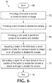
FIG. 6 is an example of a method in accordance with an implementation. -
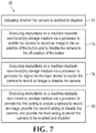
FIG. 7 is an example of additional elements of the method ofFIG. 6 in accordance with an implementation. -
FIG. 8 is an example of a machine-readable non-transitory storage medium including instructions executable by a processor in accordance with an implementation. -
FIG. 9 is an example of additional instructions executable by a processor included on or in the machine- redable non-transitory storage medium ofFIG. 8 in accordance with an implementation. -
FIG. 10 is an example of a flowchart in accordance with an implementation. - Electronic devices may include a camera that records images (still and/or video). User of such electronic devices may utilize these images with applications such as, for example, video conferencing, email, and instant messaging. Unfortunately, however, hackers or other unauthorized persons may enable the camera on such an electronic device without a user's knowledge or permission. If this occurs, the camera may be utilized by such hackers or other unauthorized persons to record images of the end user and/or the location (e.g., home, office, car, etc.) in which the end user is utilizing the electronic device. These recorded images may be used, transmitted, forwarded., sent, distributed and/or displayed without the user's knowledge or permission. This may cause security, privacy and/or other concerns for at least some of the users of such electronic devices.
- One way in which a camera of an electronic device may be disabled is to utilize a moveable door or other cover that blocks light from entering the lens of the camera to prevent recordation of images. One potential issue with such moveable doors or covers, however, is that they may require an electronic device to have a certain minimum thickness. This minimum thickness may prevent utilization of such moveable doors or covers in at least some electronic devices that are designed to be thin such as, for example, some tablets and phones. Moveable doors or covers may also add to the overall cost of an electronic device which, at least some end users may not be able to afford or be willing to pay.
- Another way in which a camera of an electronic device may be disabled is to utilize opaque tape to block light from entering the lens of the camera to prevent recordation of images. One potential issue with such opaque tape, however, is that, when removed, it may leave a residue on the lens of the camera which may degrade the quality (e.g., sharpness, contrast, color, etc.) of the images recorded by the camera. Another potential issue with such opaque tape is that it may not be readily available to an end user when he or she wants to disable the camera of his or her electronic device. An additional potential issue with such opaque tape is that it may inadvertently be placed over other components of an electronic device such as, for example, a microphone or speaker, thereby interfering with the operation of an electronic device.
- An additional way in which a camera of an electronic device may be disabled is to utilize a driver (e.g., machine-readable instructions) of the camera to disable the camera to prevent recordation of images. A potential issue with the use of such camera driver to disable the camera is that such camera driver can be hacked or otherwise compromised to enable the camera on such an electronic device without a user's knowledge or permission.
- Example implementations directed to securely disabling, as well as enabling, a camera of an electronic device are shown in
FIGs. 1∼10 . These example implementations illustrated inFIGs. 1∼10 also attempt to address the above-described potential technical challenges associated with other possible approaches to disable the camera of an electronic device. - As used herein, the term "electronic device" represents, but is not necessarily limited to, a computer, server, tablet, monitor, phone, personal digital assistant, kiosk, television, display, or combination thereof. As used herein, the term "camera" represent, but is not necessarily limited to, a device that records images, still and/or video, by utilizing a lens assembly, shutter, associated electronics, and a photosensitive member or film. Examples of a photosensitive member include, but are not limited to, a charge-coupled device (CCD) or a complementary metal-oxide semiconductor (CMOS).
- As used herein, the term "processor" represents, but is not necessarily limited to, an instruction execution system such as a computer-based system, an application specific integrated circuit (ASIC), a computing device, a hardware and/or machine-readable instruction system, or any combination thereof, that can fetch or obtain the logic from a machine-readable non-transitory storage medium and execute the instructions contained thereon. "Processor" can also include any controller, state-machine, microprocessor, logic control circuitry, cloud-based utility, service or feature, any other analogue, digital and/or mechanical implementation thereof, or any combination of the forgoing. A processor may be a component of a distributed system.
- As used herein, the term "distributed system" represents, but is not necessarily limited to, multiple processors and machine-readable non-transitory storage media in different locations or systems that communicate via a network, such as the cloud. As used herein, the term "cloud" represents, but is not necessarily limited to, computing resources (hardware and/or machine readable instructions) that are delivered as a service over a networlk (such as the internet),
- As used herein, the term "machine-readable non-transitory storage medium" represents, but is not necessarily limited to, any medium that can contain, store, retain, or maintain programs, code scripts, information, and/or data. A machine-readable non-transitory storage medium may include any one of many physical media such as, for example, electronic, magnetic, optical, electromagnetic, or semiconductor media. A machine-readable non-transitory storage medium may be a component of a distributed system. More specific examples of suitable machine-readable non-transitory storage media include, but are not limited to, a magnetic computer diskette such as floppy diskettes or hard drives, magnetic tape, a read-only memory (ROM), an erasable programmable read-only memory (EPROM), a flash drive or memory, a compact disc (CD), a digital video disk (DVD), or a memristor.
- As used herein, the term "basic input and output system" (BIOS) represent, but is not necessarily limited to, a set of executable instructions in persistent memory (e.g., ROM. EPROM, flash drive, etc.) that control input and output operations of an electronic device and/or components (e.g., a camera) thereof. As used herein, the term "button" represents, but is not necessarily limited to, a mechanical, electrical, or electromechanical device that is actuable between at least two positions, states, or conditions. Examples of a button include, but are not necessarily limited to, a capacitive sensor, a pushbutton, a key, a photodiode, a proximity sensor, and an inductive sensor.
- As used herein, the term "input device" represents, but is not necessarily limited to, a peripheral and any related driver or machine readable instructions used to provide data and/or control signals to an electronic device and/or components (e.g., a camera) thereof. Examples of an input device include, but are not limited to, a keyboard, keypad, mouse, pointer, trackball, or joystick. As used herein, the terms "include", "includes", "including", "have", "has", "having" and variations thereof, mean the same as the terms "comprise", "comprises", and "comprising" or appropriate variations thereof.
- An example of an
apparatus 10 is shown inFIG. 1 .Apparatus 10 may be part of an electronic device (not shown inFIG. 1 ).Apparatus 10 may be utilized to securely enable and disable a camera, as provided herein. As can be seen inFIG. 1 ,apparatus 10 includes acamera 12 to record an image and a basic input andoutput system engine 14 coupled tocamera 12, for example by a Universal Serial Bus (USB) interface, as generally indicated byarrow 16. Basic input andoutput system engine 14 includes a first state to enablecamera 12 to record an image, a second state to disablecamera 12, and a third state that allowscamera 12 to be enabled and disabled indpendent of basic input andoutput system engine 14. Basic input andoutput system engine 14 may represent any circuitry, processor, executable instructions, application programming interfaces (APIs), machine-readable non-transitory storage medium, or any combination thereof, that provides the above-described first, second, and third states. - As can additionally be seen in
FIG. 1 ,apparatus 10 also includes abutton 18 coupled to basic input andoutput system engine 14, as generally indicated byarrow 20.Button 18 is actuable between an on condition to enablecamera 12 to record an image when basic input andoutput system engine 14 is in the third state and an off condition to disablecamera 12 when basic input andoutput system engine 14 is in the third state. One way in whichbutton 18 may disablecamera 12 in the off condition is to remove power tocamera 12. It should be noted, that in this example ofapparatus 10,button 18 has no effect oncamera 12 when basic input andoutput system engine 14 is in either the first or second states. This feature of basic input andoutput system engine 14 provides a first high level of security to disablecamera 10 that helps to prevent hacking to enablecamera 10. This feature of basic input andoutput system engine 14 also provides a first high level of security to enablecamera 10 that helps to prevent hacking to disablecamera 10. - As can further be seen in
FIG. 1 ,apparatus 10 also includes aninput device 22 both to selectively enablecamera 12 to record an image whenbutton 18 is in the on condition and disablecamera 12 whenbutton 18 is in the on condition. This selectivity may be provided, for example, by allowing a user to choose to enable or disablecamera 12 viainput device 22. It should be noted, that in this example ofapparatus 10,input device 22 has no effect oncamera 12 whenbutton 18 is in the off condition. This feature ofbutton 18 provides a second level of security to disablecamera 10 that helps to prevent hacking of to enablecamera 10. A third level of security is also provided byinput device 22 itself which can selectively enable and disablecamera 12. - An example of an additional element of apparatus is shown in
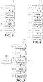
FIG. 2 . As can be seen inFIG. 2 ,apparatus 10 may also include acontroller 26 to securely enable and disablecamera 12.Controller 26 is coupled tocamera 12, as generally indicated byarrow 28, and to basic input andoutput system engine 14, as generally indicated byarrow 30. Although not shown inFIG. 2 ,controller 26 is also coupled tobutton 18 and to inputdevice 22.Controller 26 may include, for example, a Super I/O controller, a Southbridge controller, or other type of embedded controller and may be coupled tocamera 12, for example, via a secure General Purpose Input/Output (GPIO) interface. - Another example of additional elements of
apparatus 10 is shown inFIG. 3 . As can be seen inFIG. 3 ,apparatus 10 may include anindicator 32 coupled tocamera 12, as generally indicated byarrow 34, to signify whethercamera 12 is enabled or disabled.Indicator 32 may include, for example, a light source, a buzzer, a multicolored light emitting diode (LED), or multiple different colored LEDs. As can also be seen inFIG. 3 ,apparatus 10 may additionally include acomputer 36 that is coupled to Basic Input andOutput System Engine 14, as generally indicated by double-headedarrow 38. - A further example of additional elements of
apparatus 10 is shown inFIG. 4 . As can be seen inFIG. 4 ,apparatus 10 may additionally include aprocessor 40 and a machine-readablenon-transitory storage medium 42 including instructions executable byprocessor 40, as generally indicated by double-headedarrow 44, to disablecamera 12 viabutton 18, as generally indicated byarrow 46, and/or to disablecamera 12 viainput device 22, as generally indicater byarrow 48.Non-transitory storage medium 42 may also include additional instructions exucutable byprocessor 12 to enablecamera 12 viabutton 18 and/orinput device 22.Processor 40 andnon-transitory storage medium 42 may be components of anelectronic device 50. - Yet a further example of additional elements of
apparatus 10 is shown inFIG. 5 . As can be seen inFIG. 5 , basic input andoutput system engine 14 ofapparatus 10 may include aprocessor 52 and a machine-readablenon-transitory storage medium 54 including instructions executable byprocessor 52, as generally indicated by double-headedarrow 56, to enablecamera 12 andtodisable camera 12. Machine-readablenon-transitory storage medium 54 also includes instructions executable byprocessor 52 to allowcamera 12 to be enabled and disabled by, for example,button 18 andinput device 22 when basic input andoutput system engine 14 is in the third state, as discussed above. - An example of a
method 58 is shown inFIG. 6 .Method 58 may be utilized to securely enable and disable a camera, as provided herein. For example, at least a portion ofmethod 58 may be utilized inapparatus 10. As can be seen inFIG. 6 ,method 58 starts or begins 60 by providing a first state to enable a camera to record an image, as indicated byblock 62, providing a second state to disable the camera, as indicated byblock 64, and providing a third state to permit the camera to be enabled and disabled, as indicated byblock 66.Blocks output system engine 14. -
Method 58 continues by actuating a button in the third state to an on positon to enable the camera to record an image or an off position to disable the camera, as indicated byblock 68. One way in which the button may disable the camera in the off condition is to remove power to the camera.Method 58 further continues by generating a signal via an input device in the on position of the button to enable the camera to record an image or disable the camera, as indicated byblock 70.Method 58 then ends 72. - An example of additional elements of
method 58 is shown inFIG. 7 . As can be seen inFIG. 7 ,method 58 may include indicating whether the camera is enabled or disabled, as shown inblock 74. Alternatively or additionally,method 58 may include executing instructions on a machine-readable non-transitory storage medium via a processor to enable the camera to record an image in the on position of the button and to disable the camera in the off position of the button, as indicated byblock 76.Method 58 may alternatively or additionally include executing instructions on a machine-readable non-transitory storage medium via a processor to generate the signal via the input device to enable the camera to record an image or disable the camera, as indicated byblock 78. - The first state to enable a camera to record an image may include a first setting, the second state to disable the camera may include a second setting, and the third state to permit the camera to be enabled and disabled may include a third setting. In such cases,
method 58 may further include executing instructions on a machine-redable non-transitory storage medium via a processor to provide the first setting to enable a camera to record an image, provide the second setting to disable the camera, and provide the third setting to permit the camera to be enabled and disabled, as indicated byblock 80. - An example of a machine-readable
non-transitory storage medium 82 including instructions executable by aprocessor 84, as generally indicated by double-headedarrow 86, is shown inFIG. 8 . The instructions onnon-transitory storage medium 82 may be executed byprocessor 84 to securely enable and disable a camera, as provided herein. For example, the instructions onnon-transitory storage medium 82 may be utilized inapparatus 10. As another example, the instructions onnon-transitory storage medium 82 may perform at least one of the elements ofmethod 58. - As can be seen in
FIG. 8 ,non-transitory storage medium 82 includesinstructions 88 executable byprocessor 84 to provide a user interface to allow selection of a first setting to allow the camera to be enabled and disabled. As can also be seen inFIG. 8 ,non-transitory storage medium 82 includesinstructions 90 executable byprocessor 84 to enable the camera to record an image in response to actuation of a button to an on position when the third setting is selected andinstructions 92 to disable the camera in response to actuation of the button to an off position when the third setting is selected. As can additionally be seen inFIG. 8 ,non-transitory storage medium 82 includesinstructions 94 executable byprocessor 84 to disable the camera in response to a signal from an input device when the button is in the on position. - An example of additional instructions executable by
processor 84 included on or in machine-readablenon-transitory storage medium 82 is shown inFIG. 9 . As can be seen inFIG. 9 ,non-transitory storage medium 82 may includeinstructions 96 executable byprocessor 84 to actuate an indicator to signify whether the camera is enabled or disabled, - An example of a flowchart 98 is shown in
FIG. 10 . Flowchart 98 represents a way or technique to securely enable and disable a camera, as provided herein. For example,apparatus 10,method 58 and/or the instructions on machine-readablenon-transitory storage medium 82 may utilize at least a portion of the technique illustrated in flowchart 98. As can be seen inFIG. 10 , flowchart 98 starts 100 by determining whether a Basic Input and Output System (BIOS) used to at least partially control a camera is disabled 102. If yes, then the camera is disabled 104, all indicator is actuated 106 to indicate that the camera is disabled, and flowchart 98 ends 108. If the Basic Input and Output System (BIOS) used to at least partially control the camera is not disabled, then flowchart 98 continues by determining whether the Basic Input and Output System (BIOS) is enabled 110. If yes, then the camera is enabled 112, an indicator is actuated 114 to indicate the camera is enabled, and flowchart 98 ends 108. If the Basic Input and Output System (BIOS) used to at least partially control a camera is not enabled, then flowchart 98 continues as if the Basic Input and Output System (BIOS) is normal 116 (e.g., neither specifically set to enable or disable the camera). - Flowchart 98 continues by determining whether a button is disabled 118. It the button is disabled, then the camera is disabled 104, an indicator is actuated 106 to indicate that the camera is disabled, and flowchart 98 ends 108. If the button is not disabled, then flowchart 98 continues by determining whether an input device is disabled 120. If the input device is disabled, then the camera is disabled 104, an indicator is actuated 106 to indicate that the camera is disabled, and flowchart 98 ends 108. If the input device is not disabled, then the
camera 112, an indicator is actuated 114 to indicate that the camera is enabled, and flowchart 98 ends 108. - Although several drawings have been described and illustrated in detail, it is to be understood that the same are intended by way of illustration and example. These examples are not intended to be exhausitive or to be limited to the precise form disclosed. Modifications, additions, and variations may well be apparent.
- Additionally, reference to an element in the singular is not intended to mean one, unless explicitly so stated, but rather means at least one. Furthermore, unless specifically stated, any method elements, flowchart elements and/or instructions of a machine-readable non-transitory storage medium are not limited to the or order described illustrated. Moreover, no element or component is intended to be dedicated to the pubic regardless of whether the element or component is explicitly recited in the following claims.
Claims (14)
- An apparatus (10), comprising:a camera (12) to record an image;a basic input and output system engine (14) including a first state to enable the camera (12) to record an image and a second state to disable the camera; andan input device (22) both to selectively enable the camera (12) to record an image and disable the camera; characterised in that:the apparatus further comprises a button (18) actuable between on and off conditions;the first state of the basic input and output system engine (14) is arranged to enable the camera (12) regardless of the condition of the button (18), the second state of the basic input and output system engine is arranged to disable the camera regardless of the condition of the button, and the basic input and output system engine includes a third state that allows the camera to be enabled and disabled by actuating the button; andthe input device (22) is effective when the basic input and output system engine (14) is in the third state and when the button (18) is in the on condition.
- The apparatus (10) of Claim 1, further comprising a controller (26) coupled to the camera (12), the basic input and output system engine (14), the button (18), and the input device (22) to securely enable and disable the camera.
- The apparatus (10) of Claim 1, further comprising an indicator (32) to signify whether the camera (12) is enabled or disabled.
- The apparatus (10) of Claim 1, wherein the button (18) includes a capacitive sensor.
- The apparatus (10) of Claim 1, further comprising a computer (36).
- The apparatus (10) of Claim 1, further comprising a processor (40) and a machine-readable non- transitory storage medium (42) including instructions executable by the processor to enable the camera (12) to record an image via the input device (22) and to disable the camera via one of the input device and the button (18).
- The apparatus (10) of Claim 1, wherein the basic input and output system engine (14) includes a processor (52) and a machine-readable non-transitory storage medium (54) including instructions executable by the processor to enable the camera (12) to record an image, to disable the camera, and to allow the camera to be enabled and disabled.
- A method (58), comprising:providing a button (18) actuable between an on condition and an off condition;providing (62) a basic input and output system engine (14) with a first state to enable a camera (12) to record an image regardless of the condition of the button (18);providing (64) the basic input and output system engine (14) with a second state to disable the camera (12) regardless of the condition of the button (18);providing (66) the basic input and output system engine (14) with a third state to permit the camera (12) to be enabled and disabled by actuating the button (18);actuating (68) the button (18) in the third state to one of the on position to enable the camera (12) to record an image and the off position to disable the camera; andgenerating a signal via an input device (22) in the third state and in the on position of the button (18) to one of enable the camera (12) to record an image and disable the camera.
- The method (58) of Claim 8, further comprising indicating (74) whether the camera (12) is enabled or disabled.
- The method (58) of Claim 8, further comprising executing instructions on a machine-readable non-transitory storage medium (42) via a processor (40) to enable the camera (12) to record an image in the on position of the button (18) and to disable the camera in the off position of the button.
- The method (58) of Claim 8, further comprising executing instructions on a machine-readable non-transitory storage medium (42) via a processor (40) to generate the signal via the input device (22) to one of enable the camera (12) to record an image and disable the camera.
- The method (58) of Claim 8, wherein providing the first state to enable the camera (12) to record an image includes a first setting, providing the second state to disable the camera includes a second setting, and providing the third state to permit the camera to be enabled and disabled includes a third setting, and further comprising executing instructions on a machine-readable non-transitory storage medium (42, 54, 82) via a processor (40, 52, 84) to provide the first setting to enable the camera to record an image, provide the second setting to disable the camera, and provide the third setting to permit the camera to be enabled and disabled.
- A machine-readable non-transitory storage medium (82) comprising instructions for controlling a basic input and output system engine (14), a camera (12) and a button (18) actuable between on and off positions, the instructions executable by a processor (84) to:provide (88) a user interface to allow selection of one of a first setting in which the basic input and output system engine has a first state to enable a camera to record an image regardless of the condition of the button, a second setting in which the basic input and output system engine has a second state to disable the camera regardless of the condition of the button, and a third setting in which the basic input and output system engine has a third state to allow the camera to be enabled and disabled by actuating the button (18);enable (90) the camera (12) to record an image in response to actuation of the button (18) to an on position when the third setting is selected;disable (92) the camera (12) in response to actuation of the button (18) to an off position when the third setting is selected; anddisable (94) the camera (12) in response to a signal from an input device (22) when the basic input and output system engine is in the third state and the button is in the on position.
- The machine-readable non-transitory storage medium (82) of Claim 13, further comprising instructions (96) executable by the processor (84) to actuate an indicator (32) to signify whether the camera (12) is enabled or disabled.
Applications Claiming Priority (1)
| Application Number | Priority Date | Filing Date | Title |
|---|---|---|---|
| PCT/US2014/052855 WO2016032453A1 (en) | 2014-08-27 | 2014-08-27 | Enablement and disablement of cameras |
Publications (3)
| Publication Number | Publication Date |
|---|---|
| EP3195585A1 EP3195585A1 (en) | 2017-07-26 |
| EP3195585A4 EP3195585A4 (en) | 2018-04-25 |
| EP3195585B1 true EP3195585B1 (en) | 2019-03-20 |
Family
ID=55400174
Family Applications (1)
| Application Number | Title | Priority Date | Filing Date |
|---|---|---|---|
| EP14900877.3A Active EP3195585B1 (en) | 2014-08-27 | 2014-08-27 | Enablement and disablement of cameras |
Country Status (4)
| Country | Link |
|---|---|
| US (2) | US10051176B2 (en) |
| EP (1) | EP3195585B1 (en) |
| CN (1) | CN107079091B (en) |
| WO (1) | WO2016032453A1 (en) |
Families Citing this family (8)
| Publication number | Priority date | Publication date | Assignee | Title |
|---|---|---|---|---|
| AU2015224396A1 (en) * | 2015-09-08 | 2017-03-23 | Canon Kabushiki Kaisha | Camera-driven work flow synchronisation |
| US20170263254A1 (en) * | 2016-03-10 | 2017-09-14 | lntel IP Corporation | Malware-proof privacy indicator |
| CN110192193A (en) * | 2017-01-19 | 2019-08-30 | 惠普发展公司有限责任合伙企业 | Secret protection equipment |
| US10616470B2 (en) * | 2017-08-31 | 2020-04-07 | Snap Inc. | Wearable electronic device with hardware secured camera |
| WO2019117920A1 (en) * | 2017-12-14 | 2019-06-20 | Hewlett-Packard Development Company, L.P. | Enabling access to capturing devices by basic input and output systems (bios) |
| KR102503440B1 (en) * | 2018-04-12 | 2023-02-27 | 삼성전자주식회사 | An electronic device obtaining an security image using security processing module |
| EP3814781B1 (en) | 2018-06-28 | 2025-08-06 | Hewlett-Packard Development Company, L.P. | Power consumption monitorings of peripheral devices |
| CN117473578A (en) * | 2022-07-22 | 2024-01-30 | 华为技术有限公司 | Methods and related devices for controlling components |
Family Cites Families (18)
| Publication number | Priority date | Publication date | Assignee | Title |
|---|---|---|---|---|
| US6501380B1 (en) | 2000-11-10 | 2002-12-31 | Lucent Technologies Inc. | Probabilistic theft deterrence |
| CN101242493B (en) | 2003-05-20 | 2011-01-12 | 松下电器产业株式会社 | camera system |
| US7548255B2 (en) * | 2003-09-30 | 2009-06-16 | Microsoft Corporation | Method and system for capturing video on a personal computer |
| US7272403B2 (en) * | 2005-12-02 | 2007-09-18 | International Business Machines Corporation | Selective enablement and disablement of a mobile communications device based upon location |
| CN1991660A (en) * | 2005-12-30 | 2007-07-04 | 联想(北京)有限公司 | Switch unit for integration apparatus of data processing equipment |
| US7414529B2 (en) * | 2006-08-04 | 2008-08-19 | International Business Machines Corporation | Disablement of camera functionality for a portable device |
| US7706837B2 (en) * | 2006-09-01 | 2010-04-27 | Research In Motion Limited | Disabling operation of a camera on a handheld mobile communication device based upon enabling or disabling devices |
| KR20080060046A (en) * | 2006-12-26 | 2008-07-01 | 엘지전자 주식회사 | System equipped with photographing means |
| US20080270652A1 (en) * | 2007-04-30 | 2008-10-30 | Jeffrey Kevin Jeansonne | System and method of tamper-resistant control |
| TW200920105A (en) | 2007-10-31 | 2009-05-01 | Mitac Int Corp | Handheld device having independently operating camera and method thereof |
| TW200943043A (en) | 2008-04-14 | 2009-10-16 | Asustek Comp Inc | Power control method applied to embeded WebCAM of notebook computer |
| KR101537699B1 (en) | 2009-01-29 | 2015-07-20 | 엘지전자 주식회사 | Mobile terminal and method for controlling device access thereof |
| TWI482044B (en) * | 2009-07-14 | 2015-04-21 | Wistron Corp | Computer device and ip camera power control method for preventing unauthorized use of a picture-taking function |
| CN101980099B (en) * | 2010-09-27 | 2012-12-19 | 鸿富锦精密工业(深圳)有限公司 | Electronic device with camera protection function and method |
| DE202011107699U1 (en) | 2011-11-09 | 2012-01-24 | Fujitsu Technology Solutions Intellectual Property Gmbh | display device |
| CN103229138A (en) * | 2011-11-28 | 2013-07-31 | Lg电子株式会社 | Method, recording medium, and electronic device for reducing boot time |
| US8988532B2 (en) * | 2012-02-29 | 2015-03-24 | High Sec Labs Ltd. | Secure video camera device |
| TWI502314B (en) | 2012-07-11 | 2015-10-01 | Wistron Corp | Portable electronic device |
-
2014
- 2014-08-27 US US15/506,623 patent/US10051176B2/en active Active
- 2014-08-27 WO PCT/US2014/052855 patent/WO2016032453A1/en not_active Ceased
- 2014-08-27 EP EP14900877.3A patent/EP3195585B1/en active Active
- 2014-08-27 CN CN201480082884.8A patent/CN107079091B/en active Active
-
2018
- 2018-08-13 US US16/102,236 patent/US10250798B2/en not_active Expired - Fee Related
Non-Patent Citations (1)
| Title |
|---|
| None * |
Also Published As
| Publication number | Publication date |
|---|---|
| CN107079091A (en) | 2017-08-18 |
| US20170289443A1 (en) | 2017-10-05 |
| WO2016032453A1 (en) | 2016-03-03 |
| EP3195585A1 (en) | 2017-07-26 |
| US20180352147A1 (en) | 2018-12-06 |
| CN107079091B (en) | 2020-08-11 |
| US10051176B2 (en) | 2018-08-14 |
| EP3195585A4 (en) | 2018-04-25 |
| US10250798B2 (en) | 2019-04-02 |
Similar Documents
| Publication | Publication Date | Title |
|---|---|---|
| US10250798B2 (en) | Enablement and disablement of cameras | |
| EP3136648B1 (en) | Method and device for determining control authority on user device | |
| US9723222B2 (en) | Mobile terminal with a camera and method for capturing an image by the mobile terminal in self-photography mode | |
| EP3089065B1 (en) | Method and device for permission management | |
| EP3188066B1 (en) | A method and an apparatus for managing an application | |
| EP3220602B1 (en) | Method and device for accessing smart camera | |
| CN110995929A (en) | Terminal control method, device, terminal and storage medium | |
| US20160187997A1 (en) | Method and device for controlling application | |
| CN114642015B (en) | Wearable safety data device | |
| CN105119790B (en) | Apparatus control method and device | |
| EP3178029B1 (en) | Mobile device, method for displaying screen thereof, wearable device, method for driving the same, and computer-readable recording medium | |
| EP2924552B1 (en) | Method and mobile terminal for executing user instructions | |
| WO2017185569A1 (en) | Method of clearing memory, device, and electronic apparatus | |
| CN105141806B (en) | The display methods and device of image file | |
| CN106453527A (en) | Account sharing method and equipment | |
| WO2018049610A1 (en) | Permission control method and device | |
| CN105653903A (en) | Application program authority management method and device | |
| EP2765482A1 (en) | Handheld electronic apparatus and operation method thereof | |
| CN106790018B (en) | Resource sharing playing method and device | |
| CN105868624A (en) | Application program authority management method and device | |
| RU2679719C2 (en) | Method and device for controlling working condition | |
| EP3255575A1 (en) | Application triggering method and device | |
| CN111722919B (en) | Method and device for running background application program, storage medium and electronic equipment | |
| CN108037912A (en) | Show the method, apparatus of page info | |
| WO2018049611A1 (en) | Permission control method and device |
Legal Events
| Date | Code | Title | Description |
|---|---|---|---|
| STAA | Information on the status of an ep patent application or granted ep patent |
Free format text: STATUS: THE INTERNATIONAL PUBLICATION HAS BEEN MADE |
|
| PUAI | Public reference made under article 153(3) epc to a published international application that has entered the european phase |
Free format text: ORIGINAL CODE: 0009012 |
|
| STAA | Information on the status of an ep patent application or granted ep patent |
Free format text: STATUS: REQUEST FOR EXAMINATION WAS MADE |
|
| 17P | Request for examination filed |
Effective date: 20170228 |
|
| AK | Designated contracting states |
Kind code of ref document: A1 Designated state(s): AL AT BE BG CH CY CZ DE DK EE ES FI FR GB GR HR HU IE IS IT LI LT LU LV MC MK MT NL NO PL PT RO RS SE SI SK SM TR |
|
| AX | Request for extension of the european patent |
Extension state: BA ME |
|
| DAX | Request for extension of the european patent (deleted) | ||
| A4 | Supplementary search report drawn up and despatched |
Effective date: 20180322 |
|
| RIC1 | Information provided on ipc code assigned before grant |
Ipc: G06F 21/70 20130101ALI20180316BHEP Ipc: H04N 5/77 20060101ALI20180316BHEP Ipc: H04N 5/232 20060101AFI20180316BHEP Ipc: G06F 21/57 20130101ALI20180316BHEP Ipc: G06F 9/4401 20180101ALI20180316BHEP Ipc: H04N 5/225 20060101ALI20180316BHEP |
|
| GRAP | Despatch of communication of intention to grant a patent |
Free format text: ORIGINAL CODE: EPIDOSNIGR1 |
|
| RIC1 | Information provided on ipc code assigned before grant |
Ipc: G06F 9/4401 20180101ALI20181109BHEP Ipc: G06F 21/62 20130101ALI20181109BHEP Ipc: H04N 5/225 20060101ALI20181109BHEP Ipc: G06F 21/57 20130101ALI20181109BHEP Ipc: G06F 21/70 20130101ALI20181109BHEP Ipc: H04N 5/77 20060101ALI20181109BHEP Ipc: H04N 5/232 20060101AFI20181109BHEP |
|
| STAA | Information on the status of an ep patent application or granted ep patent |
Free format text: STATUS: GRANT OF PATENT IS INTENDED |
|
| INTG | Intention to grant announced |
Effective date: 20181220 |
|
| GRAS | Grant fee paid |
Free format text: ORIGINAL CODE: EPIDOSNIGR3 |
|
| RIC1 | Information provided on ipc code assigned before grant |
Ipc: G06F 21/62 20130101ALI20181109BHEP Ipc: H04N 5/225 20060101ALI20181109BHEP Ipc: G06F 9/4401 20180101ALI20181109BHEP Ipc: G06F 21/70 20130101ALI20181109BHEP Ipc: H04N 5/232 20060101AFI20181109BHEP Ipc: H04N 5/77 20060101ALI20181109BHEP Ipc: G06F 21/57 20130101ALI20181109BHEP |
|
| GRAA | (expected) grant |
Free format text: ORIGINAL CODE: 0009210 |
|
| STAA | Information on the status of an ep patent application or granted ep patent |
Free format text: STATUS: THE PATENT HAS BEEN GRANTED |
|
| AK | Designated contracting states |
Kind code of ref document: B1 Designated state(s): AL AT BE BG CH CY CZ DE DK EE ES FI FR GB GR HR HU IE IS IT LI LT LU LV MC MK MT NL NO PL PT RO RS SE SI SK SM TR |
|
| REG | Reference to a national code |
Ref country code: GB Ref legal event code: FG4D |
|
| REG | Reference to a national code |
Ref country code: CH Ref legal event code: EP |
|
| REG | Reference to a national code |
Ref country code: DE Ref legal event code: R096 Ref document number: 602014043468 Country of ref document: DE |
|
| REG | Reference to a national code |
Ref country code: AT Ref legal event code: REF Ref document number: 1111716 Country of ref document: AT Kind code of ref document: T Effective date: 20190415 |
|
| REG | Reference to a national code |
Ref country code: IE Ref legal event code: FG4D |
|
| RAP2 | Party data changed (patent owner data changed or rights of a patent transferred) |
Owner name: HEWLETT-PACKARD DEVELOPMENT COMPANY, L.P. |
|
| REG | Reference to a national code |
Ref country code: NL Ref legal event code: MP Effective date: 20190320 |
|
| PG25 | Lapsed in a contracting state [announced via postgrant information from national office to epo] |
Ref country code: LT Free format text: LAPSE BECAUSE OF FAILURE TO SUBMIT A TRANSLATION OF THE DESCRIPTION OR TO PAY THE FEE WITHIN THE PRESCRIBED TIME-LIMIT Effective date: 20190320 Ref country code: SE Free format text: LAPSE BECAUSE OF FAILURE TO SUBMIT A TRANSLATION OF THE DESCRIPTION OR TO PAY THE FEE WITHIN THE PRESCRIBED TIME-LIMIT Effective date: 20190320 Ref country code: FI Free format text: LAPSE BECAUSE OF FAILURE TO SUBMIT A TRANSLATION OF THE DESCRIPTION OR TO PAY THE FEE WITHIN THE PRESCRIBED TIME-LIMIT Effective date: 20190320 Ref country code: NO Free format text: LAPSE BECAUSE OF FAILURE TO SUBMIT A TRANSLATION OF THE DESCRIPTION OR TO PAY THE FEE WITHIN THE PRESCRIBED TIME-LIMIT Effective date: 20190620 |
|
| REG | Reference to a national code |
Ref country code: LT Ref legal event code: MG4D |
|
| PG25 | Lapsed in a contracting state [announced via postgrant information from national office to epo] |
Ref country code: LV Free format text: LAPSE BECAUSE OF FAILURE TO SUBMIT A TRANSLATION OF THE DESCRIPTION OR TO PAY THE FEE WITHIN THE PRESCRIBED TIME-LIMIT Effective date: 20190320 Ref country code: GR Free format text: LAPSE BECAUSE OF FAILURE TO SUBMIT A TRANSLATION OF THE DESCRIPTION OR TO PAY THE FEE WITHIN THE PRESCRIBED TIME-LIMIT Effective date: 20190621 Ref country code: HR Free format text: LAPSE BECAUSE OF FAILURE TO SUBMIT A TRANSLATION OF THE DESCRIPTION OR TO PAY THE FEE WITHIN THE PRESCRIBED TIME-LIMIT Effective date: 20190320 Ref country code: NL Free format text: LAPSE BECAUSE OF FAILURE TO SUBMIT A TRANSLATION OF THE DESCRIPTION OR TO PAY THE FEE WITHIN THE PRESCRIBED TIME-LIMIT Effective date: 20190320 Ref country code: RS Free format text: LAPSE BECAUSE OF FAILURE TO SUBMIT A TRANSLATION OF THE DESCRIPTION OR TO PAY THE FEE WITHIN THE PRESCRIBED TIME-LIMIT Effective date: 20190320 Ref country code: BG Free format text: LAPSE BECAUSE OF FAILURE TO SUBMIT A TRANSLATION OF THE DESCRIPTION OR TO PAY THE FEE WITHIN THE PRESCRIBED TIME-LIMIT Effective date: 20190620 |
|
| REG | Reference to a national code |
Ref country code: AT Ref legal event code: MK05 Ref document number: 1111716 Country of ref document: AT Kind code of ref document: T Effective date: 20190320 |
|
| PG25 | Lapsed in a contracting state [announced via postgrant information from national office to epo] |
Ref country code: AL Free format text: LAPSE BECAUSE OF FAILURE TO SUBMIT A TRANSLATION OF THE DESCRIPTION OR TO PAY THE FEE WITHIN THE PRESCRIBED TIME-LIMIT Effective date: 20190320 Ref country code: ES Free format text: LAPSE BECAUSE OF FAILURE TO SUBMIT A TRANSLATION OF THE DESCRIPTION OR TO PAY THE FEE WITHIN THE PRESCRIBED TIME-LIMIT Effective date: 20190320 Ref country code: PT Free format text: LAPSE BECAUSE OF FAILURE TO SUBMIT A TRANSLATION OF THE DESCRIPTION OR TO PAY THE FEE WITHIN THE PRESCRIBED TIME-LIMIT Effective date: 20190720 Ref country code: CZ Free format text: LAPSE BECAUSE OF FAILURE TO SUBMIT A TRANSLATION OF THE DESCRIPTION OR TO PAY THE FEE WITHIN THE PRESCRIBED TIME-LIMIT Effective date: 20190320 Ref country code: RO Free format text: LAPSE BECAUSE OF FAILURE TO SUBMIT A TRANSLATION OF THE DESCRIPTION OR TO PAY THE FEE WITHIN THE PRESCRIBED TIME-LIMIT Effective date: 20190320 Ref country code: SK Free format text: LAPSE BECAUSE OF FAILURE TO SUBMIT A TRANSLATION OF THE DESCRIPTION OR TO PAY THE FEE WITHIN THE PRESCRIBED TIME-LIMIT Effective date: 20190320 Ref country code: EE Free format text: LAPSE BECAUSE OF FAILURE TO SUBMIT A TRANSLATION OF THE DESCRIPTION OR TO PAY THE FEE WITHIN THE PRESCRIBED TIME-LIMIT Effective date: 20190320 Ref country code: IT Free format text: LAPSE BECAUSE OF FAILURE TO SUBMIT A TRANSLATION OF THE DESCRIPTION OR TO PAY THE FEE WITHIN THE PRESCRIBED TIME-LIMIT Effective date: 20190320 |
|
| PG25 | Lapsed in a contracting state [announced via postgrant information from national office to epo] |
Ref country code: PL Free format text: LAPSE BECAUSE OF FAILURE TO SUBMIT A TRANSLATION OF THE DESCRIPTION OR TO PAY THE FEE WITHIN THE PRESCRIBED TIME-LIMIT Effective date: 20190320 Ref country code: SM Free format text: LAPSE BECAUSE OF FAILURE TO SUBMIT A TRANSLATION OF THE DESCRIPTION OR TO PAY THE FEE WITHIN THE PRESCRIBED TIME-LIMIT Effective date: 20190320 |
|
| PG25 | Lapsed in a contracting state [announced via postgrant information from national office to epo] |
Ref country code: IS Free format text: LAPSE BECAUSE OF FAILURE TO SUBMIT A TRANSLATION OF THE DESCRIPTION OR TO PAY THE FEE WITHIN THE PRESCRIBED TIME-LIMIT Effective date: 20190720 Ref country code: AT Free format text: LAPSE BECAUSE OF FAILURE TO SUBMIT A TRANSLATION OF THE DESCRIPTION OR TO PAY THE FEE WITHIN THE PRESCRIBED TIME-LIMIT Effective date: 20190320 |
|
| REG | Reference to a national code |
Ref country code: DE Ref legal event code: R097 Ref document number: 602014043468 Country of ref document: DE |
|
| PLBE | No opposition filed within time limit |
Free format text: ORIGINAL CODE: 0009261 |
|
| STAA | Information on the status of an ep patent application or granted ep patent |
Free format text: STATUS: NO OPPOSITION FILED WITHIN TIME LIMIT |
|
| PG25 | Lapsed in a contracting state [announced via postgrant information from national office to epo] |
Ref country code: DK Free format text: LAPSE BECAUSE OF FAILURE TO SUBMIT A TRANSLATION OF THE DESCRIPTION OR TO PAY THE FEE WITHIN THE PRESCRIBED TIME-LIMIT Effective date: 20190320 |
|
| 26N | No opposition filed |
Effective date: 20200102 |
|
| PG25 | Lapsed in a contracting state [announced via postgrant information from national office to epo] |
Ref country code: SI Free format text: LAPSE BECAUSE OF FAILURE TO SUBMIT A TRANSLATION OF THE DESCRIPTION OR TO PAY THE FEE WITHIN THE PRESCRIBED TIME-LIMIT Effective date: 20190320 |
|
| PG25 | Lapsed in a contracting state [announced via postgrant information from national office to epo] |
Ref country code: TR Free format text: LAPSE BECAUSE OF FAILURE TO SUBMIT A TRANSLATION OF THE DESCRIPTION OR TO PAY THE FEE WITHIN THE PRESCRIBED TIME-LIMIT Effective date: 20190320 |
|
| PG25 | Lapsed in a contracting state [announced via postgrant information from national office to epo] |
Ref country code: MC Free format text: LAPSE BECAUSE OF FAILURE TO SUBMIT A TRANSLATION OF THE DESCRIPTION OR TO PAY THE FEE WITHIN THE PRESCRIBED TIME-LIMIT Effective date: 20190320 Ref country code: LU Free format text: LAPSE BECAUSE OF NON-PAYMENT OF DUE FEES Effective date: 20190827 Ref country code: CH Free format text: LAPSE BECAUSE OF NON-PAYMENT OF DUE FEES Effective date: 20190831 Ref country code: LI Free format text: LAPSE BECAUSE OF NON-PAYMENT OF DUE FEES Effective date: 20190831 |
|
| REG | Reference to a national code |
Ref country code: BE Ref legal event code: MM Effective date: 20190831 |
|
| PG25 | Lapsed in a contracting state [announced via postgrant information from national office to epo] |
Ref country code: IE Free format text: LAPSE BECAUSE OF NON-PAYMENT OF DUE FEES Effective date: 20190827 |
|
| PG25 | Lapsed in a contracting state [announced via postgrant information from national office to epo] |
Ref country code: BE Free format text: LAPSE BECAUSE OF NON-PAYMENT OF DUE FEES Effective date: 20190831 |
|
| PG25 | Lapsed in a contracting state [announced via postgrant information from national office to epo] |
Ref country code: CY Free format text: LAPSE BECAUSE OF FAILURE TO SUBMIT A TRANSLATION OF THE DESCRIPTION OR TO PAY THE FEE WITHIN THE PRESCRIBED TIME-LIMIT Effective date: 20190320 |
|
| PG25 | Lapsed in a contracting state [announced via postgrant information from national office to epo] |
Ref country code: HU Free format text: LAPSE BECAUSE OF FAILURE TO SUBMIT A TRANSLATION OF THE DESCRIPTION OR TO PAY THE FEE WITHIN THE PRESCRIBED TIME-LIMIT; INVALID AB INITIO Effective date: 20140827 Ref country code: MT Free format text: LAPSE BECAUSE OF FAILURE TO SUBMIT A TRANSLATION OF THE DESCRIPTION OR TO PAY THE FEE WITHIN THE PRESCRIBED TIME-LIMIT Effective date: 20190320 |
|
| PG25 | Lapsed in a contracting state [announced via postgrant information from national office to epo] |
Ref country code: MK Free format text: LAPSE BECAUSE OF FAILURE TO SUBMIT A TRANSLATION OF THE DESCRIPTION OR TO PAY THE FEE WITHIN THE PRESCRIBED TIME-LIMIT Effective date: 20190320 |
|
| REG | Reference to a national code |
Ref country code: DE Ref legal event code: R079 Ref document number: 602014043468 Country of ref document: DE Free format text: PREVIOUS MAIN CLASS: H04N0005232000 Ipc: H04N0023600000 |
|
| PGFP | Annual fee paid to national office [announced via postgrant information from national office to epo] |
Ref country code: GB Payment date: 20230720 Year of fee payment: 10 |
|
| PGFP | Annual fee paid to national office [announced via postgrant information from national office to epo] |
Ref country code: FR Payment date: 20230720 Year of fee payment: 10 |
|
| GBPC | Gb: european patent ceased through non-payment of renewal fee |
Effective date: 20240827 |
|
| PG25 | Lapsed in a contracting state [announced via postgrant information from national office to epo] |
Ref country code: GB Free format text: LAPSE BECAUSE OF NON-PAYMENT OF DUE FEES Effective date: 20240827 |
|
| PG25 | Lapsed in a contracting state [announced via postgrant information from national office to epo] |
Ref country code: FR Free format text: LAPSE BECAUSE OF NON-PAYMENT OF DUE FEES Effective date: 20240831 |
|
| PGFP | Annual fee paid to national office [announced via postgrant information from national office to epo] |
Ref country code: DE Payment date: 20250724 Year of fee payment: 12 |