EP3195279B1 - Detecting uv-fluorescent indicia with a camera - Google Patents
Detecting uv-fluorescent indicia with a camera Download PDFInfo
- Publication number
- EP3195279B1 EP3195279B1 EP15778791.2A EP15778791A EP3195279B1 EP 3195279 B1 EP3195279 B1 EP 3195279B1 EP 15778791 A EP15778791 A EP 15778791A EP 3195279 B1 EP3195279 B1 EP 3195279B1
- Authority
- EP
- European Patent Office
- Prior art keywords
- image
- indicia
- camera
- light
- flash
- Prior art date
- Legal status (The legal status is an assumption and is not a legal conclusion. Google has not performed a legal analysis and makes no representation as to the accuracy of the status listed.)
- Active
Links
Images








Classifications
-
- G—PHYSICS
- G07—CHECKING-DEVICES
- G07D—HANDLING OF COINS OR VALUABLE PAPERS, e.g. TESTING, SORTING BY DENOMINATIONS, COUNTING, DISPENSING, CHANGING OR DEPOSITING
- G07D7/00—Testing specially adapted to determine the identity or genuineness of valuable papers or for segregating those which are unacceptable, e.g. banknotes that are alien to a currency
- G07D7/06—Testing specially adapted to determine the identity or genuineness of valuable papers or for segregating those which are unacceptable, e.g. banknotes that are alien to a currency using wave or particle radiation
- G07D7/12—Visible light, infrared or ultraviolet radiation
- G07D7/1205—Testing spectral properties
-
- G—PHYSICS
- G06—COMPUTING OR CALCULATING; COUNTING
- G06K—GRAPHICAL DATA READING; PRESENTATION OF DATA; RECORD CARRIERS; HANDLING RECORD CARRIERS
- G06K7/00—Methods or arrangements for sensing record carriers, e.g. for reading patterns
- G06K7/10—Methods or arrangements for sensing record carriers, e.g. for reading patterns by electromagnetic radiation, e.g. optical sensing; by corpuscular radiation
- G06K7/10544—Methods or arrangements for sensing record carriers, e.g. for reading patterns by electromagnetic radiation, e.g. optical sensing; by corpuscular radiation by scanning of the records by radiation in the optical part of the electromagnetic spectrum
- G06K7/10712—Fixed beam scanning
- G06K7/10722—Photodetector array or CCD scanning
- G06K7/10732—Light sources
-
- G—PHYSICS
- G06—COMPUTING OR CALCULATING; COUNTING
- G06K—GRAPHICAL DATA READING; PRESENTATION OF DATA; RECORD CARRIERS; HANDLING RECORD CARRIERS
- G06K19/00—Record carriers for use with machines and with at least a part designed to carry digital markings
- G06K19/06—Record carriers for use with machines and with at least a part designed to carry digital markings characterised by the kind of the digital marking, e.g. shape, nature, code
- G06K19/06009—Record carriers for use with machines and with at least a part designed to carry digital markings characterised by the kind of the digital marking, e.g. shape, nature, code with optically detectable marking
-
- G—PHYSICS
- G06—COMPUTING OR CALCULATING; COUNTING
- G06K—GRAPHICAL DATA READING; PRESENTATION OF DATA; RECORD CARRIERS; HANDLING RECORD CARRIERS
- G06K7/00—Methods or arrangements for sensing record carriers, e.g. for reading patterns
- G06K7/10—Methods or arrangements for sensing record carriers, e.g. for reading patterns by electromagnetic radiation, e.g. optical sensing; by corpuscular radiation
- G06K7/10544—Methods or arrangements for sensing record carriers, e.g. for reading patterns by electromagnetic radiation, e.g. optical sensing; by corpuscular radiation by scanning of the records by radiation in the optical part of the electromagnetic spectrum
- G06K7/10821—Methods or arrangements for sensing record carriers, e.g. for reading patterns by electromagnetic radiation, e.g. optical sensing; by corpuscular radiation by scanning of the records by radiation in the optical part of the electromagnetic spectrum further details of bar or optical code scanning devices
- G06K7/1095—Methods or arrangements for sensing record carriers, e.g. for reading patterns by electromagnetic radiation, e.g. optical sensing; by corpuscular radiation by scanning of the records by radiation in the optical part of the electromagnetic spectrum further details of bar or optical code scanning devices the scanner comprising adaptations for scanning a record carrier that is displayed on a display-screen or the like
-
- G—PHYSICS
- G07—CHECKING-DEVICES
- G07D—HANDLING OF COINS OR VALUABLE PAPERS, e.g. TESTING, SORTING BY DENOMINATIONS, COUNTING, DISPENSING, CHANGING OR DEPOSITING
- G07D7/00—Testing specially adapted to determine the identity or genuineness of valuable papers or for segregating those which are unacceptable, e.g. banknotes that are alien to a currency
- G07D7/06—Testing specially adapted to determine the identity or genuineness of valuable papers or for segregating those which are unacceptable, e.g. banknotes that are alien to a currency using wave or particle radiation
- G07D7/12—Visible light, infrared or ultraviolet radiation
- G07D7/128—Viewing devices
-
- H—ELECTRICITY
- H04—ELECTRIC COMMUNICATION TECHNIQUE
- H04N—PICTORIAL COMMUNICATION, e.g. TELEVISION
- H04N23/00—Cameras or camera modules comprising electronic image sensors; Control thereof
- H04N23/56—Cameras or camera modules comprising electronic image sensors; Control thereof provided with illuminating means
-
- G—PHYSICS
- G06—COMPUTING OR CALCULATING; COUNTING
- G06K—GRAPHICAL DATA READING; PRESENTATION OF DATA; RECORD CARRIERS; HANDLING RECORD CARRIERS
- G06K7/00—Methods or arrangements for sensing record carriers, e.g. for reading patterns
- G06K7/10—Methods or arrangements for sensing record carriers, e.g. for reading patterns by electromagnetic radiation, e.g. optical sensing; by corpuscular radiation
- G06K2007/10524—Hand-held scanners
Definitions
- This invention relates in general to authentication of objects having fluorescent indicia and in particular to authentication of objects using a cell phone.
- UV ultraviolet
- the security information is invisible under normal, visible lighting but is revealed when a UV light source is used, such as a UV flashlight.
- the product or document of interest is authenticated by revealing the invisible indicia with the UV flashlight and visually verifying the image or human-readable text or code that is revealed. While this can be an effective security feature, the authentication process has limitations.
- mobile devices are extremely useful when conducting investigations. It is also useful to be able to acquire images of indicia, display such images and analyze them with mobile devices.
- smart phones include useful sensors, flashes for light exposures, and microprocessors for processing data and images.
- such devices are designed to detect visible indicia and are not suitable for detecting covert invisible indicia.
- the data can be printed in the form of a machine-readable code rather than a human-readable code, for example a linear or two-dimensional bar code. It is therefore useful to be able to quickly and conveniently decode a revealed, covert machine-readable code to be able to quickly authenticate the item. Again, in these cases, a UV flashlight is insufficient to support the required workflow.
- phosphorescent materials can be used to create invisible indicia.
- Phosphorescent materials not only have a signature wavelength of light that is emitted, they also have a signature rate of decay of that emission. It is well known that rates of decay can be determined by measuring the intensity of emission at varying time points. It is also well known that the wavelength of emission and rate of decay of emission are characteristics that can be used to identify phosphorescent materials.
- DE 10 2011 077904 A discloses an illumination unit which illuminates a document arranged in camera space surrounded by housing, by a controller coupled with an interface.
- a receiving unit is arranged at outer side, to receive a mobile phone equipped with a camera.
- a camera lens is arranged at front side of opening formed in housing, for detecting the document in the camera space.
- the interface is connected to an interface of mobile phone, to control the illumination unit by an application executed in a processor unit of mobile phone.
- a system for detecting UV-light-fluorescent indicia with a camera includes a camera flash that emits visible light, a conversion device mounted over the camera flash that converts the emitted visible light to UV light, and a sensor that captures a visible- light image of the indicia after the indicia is exposed to the U V light.
- the conversion device comprises a photovoltaic device that converts the visible light emitted by the camera flash to electrical power, and a UV lamp that converts the electric power to UV light.
- the conversion device can also contain a capacitor.
- the conversion device can be affixed to the camera in any of a number of ways including via adhesives, mechanical hardware, and magnets.
- the conversion device can also be incorporated into a case or a shell that is attached to the camera, for example in a manner similar to cases and shells that are used with mobile phones (also referred to as cell phones and smart phones) or tablet devices.
- the method can further involve analyzing the captured image with a microprocessor, using the microprocessor to compare the analyzed image to stored, reference, or standard information to determine a match, and then authenticating the image if there is a match. By association, if the image is authentic then so is the item having the image.
- the system can further be configured for displaying the captured image with a display on the camera and comparing the displayed image to a stored or reference or standard image and authenticating the image (and therefore item) if there is a match.
- the system can further be configured for transmitting the captured image from the camera to a remote computer for comparison to a stored, reference or standard image and authenticating the image (and therefore item) if there is a match.
- the result of the authentication audit can then be transmitted back to the camera.
- the camera, flash, sensor, microprocessor and memory are components of a cell phone or smart phone.
- the UV-light-fluorescent indicia comprise a plurality of UV-responsive materials that can differ in their characteristic response to UV illumination.
- the response characteristic can be color of emitted light, brightness (or luminance) of emitted light, or rate of decay of emitted light.
- the indicia can be an image, text, a graphic element, a bar code, or a logo.
- the present invention will be directed in particular to elements forming part of, or in cooperation more directly with the apparatus in accordance with the present invention. It is to be understood that elements not specifically shown or described may take various forms well known to those skilled in the art.
- FIG. 1 shows a schematic representation of a camera 18 comprising a flash 20, a sensor 22, a microprocessor 26, and a memory 28.
- a visible-to-UV light conversion device 24 Mounted in front of the flash is a visible-to-UV light conversion device 24. This device transforms the incident visible light 15 from the flash 20 into UV light 16.
- the conversion device 24 can be attached to the camera 18 by way of a clamp, magnet, adhesive, shell, or sleeve or other methods of attachment.
- the emitted UV light 16 exposes an object 12 with invisible indicia 14.
- the indicia 14 absorb UV light and emit visible light 17.
- the visible light is captured by the sensor 22 thus capturing a digital image of the indicia 14.
- the digital image is read by the microprocessor 26 and stored in the memory 28.
- the microprocessor 26 can, for example, be used to compare the captured image to a stored reference image of an authentic object and the authentication process is based on the similarity of the captured image and the stored reference image.
- the invisible indicia could also be printed in the form of a machine readable code, for example a one or two-dimensional barcode. Examples of these barcodes are Data Matrix barcodes, QR-codes, linear barcode formats like 2 of 5 or code-128.
- the microprocessor analyzes the image of the invisible indicia and decodes the barcode using a decoding algorithm. Barcode decoding algorithms are well known and widely available.
- the decoded data are used to authenticate the object, by, for example, comparing the code value to stored values of valid codes.
- indicia can be authenticated by comparing a captured image of the indicia to a stored reference image.
- the captured image can be analyzed, for example by processor 26, to extract information from the captured image and the extracted information compared to reference information to authenticate the indicia if a match is found.
- luminescence The emission of light by a material or substance that has absorbed light, usually of a different wavelength, is referred to as luminescence.
- Two categories of luminescence are fluorescence and phosphorescence. Fluorescence is characterized by nearly immediate reradiation that ceases instantly when the incident light stops. Reradiation that continues for a noticeable time after the incident light has stopped is referred to as phosphorescence. Certain materials can also change color upon exposure to light. This effect is called photochromism. Copper-activated zinc sulfide or rate earth-doped strontium aluminates are examples of materials that exhibit phosphorescence with long phosphorescence lifetimes.
- FIG. 2 shows a schematic representation of the visible-to-UV light conversion device 24. It includes a photovoltaic device 30 that converts the incident visible light 15 into electrical energy. This photovoltaic device 30 is connected via electrical connections 34 to a UV lamp 32. The UV lamp 32 uses the electrical energy supplied by the photovoltaic device 30 to generate UV light. A light shield 36 blocks visible light and prevents it from reaching the object 12.
- An example of a UV lamp is the UV LED, part number XSL-370-3E, supplied by Roithner Lasertechnik GmbH, Vienna, Austria. This LED emits UV light of 370 nm wavelength when supplied with a typical voltage of 3.3 V at a current of 1 mA.
- a typical single silicon photocell used as a photovoltaic device 30 has an output voltage of just 0.6 V (open circuit). At peak power, output voltages are typically 15-20% lower. Therefore, in such an embodiment the output voltage of a single silicon photocell is insufficient to operate the UV LED.
- Another way to increase the voltage of a photovoltaic cell is to connect several photovoltaic cells in series. While most of the serially connected photovoltaic devices are large area solar cells and therefore unsuitable to collect the light in close proximity from the small flash of a camera 18, a few devices exist that consist of serially connected photovoltaic devices with a small active area.
- One example of such a device is a 4V output photo cell, part number CPC1842N, by Clare Inc, Beverly, MA. This device is rated to produce 4V/0.1mA under direct sunlight. It has an active area of 3.5 mm by 2.7 mm, which is comparable in size to the active area of a white LED flash used in most smart phone cameras.
- FIG. 3 shows the transient voltage obtained from CPC1842N connected to a resistive load of 3.3 kOhm.
- the flash Prior to image capture the flash operates at a reduced current (torch mode) to assist focusing.
- the flash operates at a higher current for a duration of 40 milliseconds.
- the voltage measured at the output of the photovoltaic device is 3.45V. This equates to a current of 1.04 mA flowing through the 3.3 kOhm load resistor.
- This experiment demonstrates that the voltage and current output of the photovoltaic device is sufficient to operate the UV LED XSL-370-3E.
- FIG. 4 shows a representation of a code captured with the Samsung Galaxy S3 smart phone with attached visible-to-UV light conversion device 24.
- the object 12 is a piece of paper with indicia printed with a UV-to-red fluorescent ink available as KODAK NEXPRESS Red Fluorescing Dry Ink from Eastman Kodak, Rochester, NY.
- the indicia are invisible under normal, visible light, but fluoresce under UV light to emit red light that can be detected by the sensor 22 in the camera 18.
- the captured image can be analyzed and decoded by a QR decoder.
- the result of the decoding of the image in FIG. 4 is the string http://www.kodak.com/go/nexpress.
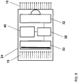
- FIG. 5 shows a variant of the visible-to-UV light conversion device 24 that incorporates control electronics 38 and energy storage 40 (capacitor or rechargeable battery) in addition to the components shown in FIG. 2 .
- the purpose of this addition is to capture the light of the flash that is emitted during the focusing operation, convert it to electrical energy using the photovoltaic device 30 and store the converted electrical energy in the energy storage device 40. During image capture, this energy is added to the energy that is available from the flash during image capture and used to power the UV lamp.
- the control electronics control energy capture, storage and release. The difference in the light intensities of the flash and torch mode, when translated into voltage or current by the photovoltaic device can be used to distinguish the energy collection and storage from the energy release phases of the focusing and image capture process.
- FIG. 6 shows the front side 100 and back side 101 of a smart phone.
- a display 110 is located on the front side.
- the back side comprises camera 18 and flash 20.
- the captured image of the object 12 containing invisible indicia 14 can be displayed on the display 110 in order to enable the operator to compare the displayed image to an expected standard and to ensure that converted light from the flash 20 reaches the object 12.
- the smart phone also contains a wireless transmitter and receiver allowing bidirectional wireless data transmission 120 with a remote computer 122, for example via a local area network, Bluetooth connection, or a cellular telephony network. This network connection allows the device to transmit the captured image to a remote computer where it is analyzed and compared to a standard to determine a match.
- the invisible indicia comprise a machine readable code
- it can be decoded by the microprocessor of the smart phone and the decoded data is sent via the wireless network to the remote computer to be compared to stored values of authentic objects.
- the result of the analysis by the remote computer can be transmitted back to the smart phone and displayed to the operator.
- the local microprocessor 26 in the camera 18 performs the comparison to reference data stored in the local memory 28 to authenticate the object.
- FIG. 7 shows the visible-to-UV light conversion device 24 placed over the flash 20.
- FIG. 8 is a schematic representation of an object 12 wherein the indicia consist of two UV-responsive materials 130 and 132 that are each spatially arranged in a pattern.
- the two materials 130 and 132 have a different response to the incident UV light and can differ in their color of emission, brightness of emission, rate of decay of emission, or a combination of these properties. Brightness of emission is also referred to as luminance.
- material 130 could be a UV-to-green emissive material with a long lifetime of emission whereas material 132 could be a UV-to-red emissive material with a short lifetime of emission.
- UV-responsive materials can be in the form of inks, dyes, pigments, molecules, or particles.
- FIG. 9 is a schematic representation of an object 12 wherein the indicia consist of two UV-responsive materials 130 and 132 that are randomly distributed.
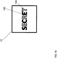
- FIG. 10 is a schematic representation of an object 12 wherein the indicia consist of two UV-responsive materials 130 and 132 printed to form parts of a text.
- the UV-responsive materials in the indicia can form an image, a color image, a pattern, graphic element, random arrangement, or text.
- FIG. 11 is a schematic representation of a sequence of image captures of the object 12 in FIG. 10 wherein the first image 150 is captured with the sensor when the flash is not operated.
- the second image is captured when the flash is operated and the third image is captured after the second image capture when the flash is not operated.
- the three images are acquired at regular intervals, although they could be acquired at irregular intervals.
- Many cameras have a mode of operation that allows image capture to occur in a burst mode, that is, multiple images are captured in rapid succession.
- a burst mode can apply to either the flash (multiple flashes in rapid succession) or to image capture (multiple images captured in rapid succession).
- the flash burst mode can control the flash 20 to operate at regular intervals or at irregular intervals.
- the image burst mode can control the sensor 22 to operate at regular intervals or at irregular intervals.
- the indicia are invisible because there is no incident UV light from the visible-to-UV light conversion device 24 (because the flash 20 was not operated).
- the second image 152 the indicia 14 are visible because the flash 20 is operated and the visible-to-UV light conversion device 24 is illuminating the object 12 with UV light.
- the last image 154 that is acquired without flash, the indicia 14 are partly visible, because one of the UV-responsive materials 130 has an emission lifetime that is longer than the time between the capture of images 152 and 154 whereas the other UV-responsive material 132 has an emission lifetime that is shorter than the time between the capture of images 152 and 154.
- UV-responsive materials with a long emission lifetime are rare-earth-doped strontium aluminates or copper-activated zinc sulfide.
- materials with a short emission lifetime include UV fluorescent dyes such as 7-hydroxycoumarin, CAS RN 93-35-6 or Disodium 2,2'-([1,1'-biphenyl]-4,4'-diyldivinylene)bis(benzenesulphonate) CAS RN 27344-41-8 .
- Materials with intermediate emission lifetimes include europium chelates such as Eu[(3-thenoyltrifluoroacetonate) 3 (H 2 O) 2 ] CAS RN 21392-96-1 .
- FIG. 12 is a schematic representation of a sequence of image captures of the object 12 in FIG. 10 where the first image 160 is captured with the sensor when the flash 20 is not operated.
- the second and third images 162, 164 are captured when the flash 20 is operated.
- the indicia 14 are invisible because there is no incident UV light from the visible-to-UV light conversion device 24.
- the second and third image 162 and 164 the indicia 14 are visible because the flash 20 is operated, and the visible-to-UV light conversion device 24 is illuminating the object 12 with UV light.
- the two UV light responsive materials 130, 132 differ in their response to UV illumination. Material 130 reacts instantly to the exciting UV radiation reaching a stationary value of brightness in images 162 and 164.
- UV light responsive material 132 reacts slowly to the incident UV radiation and builds up emission intensity over time. Therefore the brightness of UV-responsive material 132 is higher in captured image 164 than image 162.
- brightness (or emission intensity) differences are depicted by representing the indicia 14 with a normal font for the less bright state of the characters "R", "T", and the first "E” in image 162 and a bold font for those same characters in the brighter state of image 164.
- FIG. 13 shows the time behavior of the emission of two UV-responsive materials undergoing two sequential flash exposures. Illustrated are the moments in time corresponding to the first flash exposure 140, the first image acquisition 141, the second flash exposure 142, the second image acquisition 143, and a third image acquisition 145.
- a threshold value 136 indicates the emission intensity level above which the pixel is considered in the on or 1 state and below which the pixel is considered to be in the off or 0 state.
- a microprocessor e.g. microprocessor 26 in FIG. 1
- a microprocessor can analyze the image for emission intensity and determine the binary value, 1 or 0, for example by comparing the pixel emission intensity level to the threshold value 136.
- the pixels that represent material 132 are on whereas the pixels that represent material 130 are off.
- the pixels that represent both material 132 and 130 are on because material 130 with the long emission lifetime retains some emission intensity from the first flash exposure 140 and consequently the second flash exposure 142 increases the emission intensity above the threshold level 136.
- the pixels that represent material 130 are on because material 130 with the long emission lifetime retains some emission intensity from the first and second flash exposures 140, 142.
- the material 132 has decayed below the threshold level 136.
- a comparison of the pixels in the three images makes it possible to distinguish indicia on an object that contain both types of UV-responsive materials from an object with indicia that are composed of just one of the UV-responsive materials or none at all.
- Authentication can depend on the location of the pixels of material 130 and pixels of material 132 in all three images.
- both the location and the temporal sequence of pixels form an authentication code dependent upon the sequence and timing of the flashes and the image captures. Note that, in this example, the image captures are at irregular intervals.
- more than two flashes are used in sequence and more than two or more than three image captures are employed to authenticate an object 12.
- material 130 could require three flashes to emit light with an intensity greater than the threshold level 136.
- authentication can depend upon the presence of the different UV-responsive material, their rate of decay in response to UV-light exposure, to a pre-determined sequence of UV-light exposures, and to a pre-determined sequence of image captures.
- the UV-light exposures and image captures can be at regular intervals or irregular intervals.
- Image captures can be made immediately after a flash or independently of a flash. The sequence and timing of flashes and image captures can be used to control temporal material emission and thus to determine authenticity.
- the different materials can be located at spatially distinct locations, as in FIGS. 8-12 .
- the different materials are located in a visually common location. As the materials acquire energy or decay at different rates, the light emission at the visually common location can change color. For example, referring to FIG. 12 , if material 130 emits red light and material 132 emits green light in response to UV illumination, the visually common location would change over time from green (green material 132 only) to yellow (both red and green materials 130, 132) to red (only red material 130).
- the first captured image can be used to determine the number and timing of subsequent flash exposures and image captures.
- the first image can be analyzed to determine information that is then used to find flash and image capture timing information for subsequent flashes and image captures and to find authentication information, for example in a lookup table in memory 28.
- the time until a second flash or image capture can depend upon information extracted from an image capture with a flash at a first time.
Landscapes
- Physics & Mathematics (AREA)
- General Health & Medical Sciences (AREA)
- Toxicology (AREA)
- Health & Medical Sciences (AREA)
- General Physics & Mathematics (AREA)
- Engineering & Computer Science (AREA)
- Electromagnetism (AREA)
- Theoretical Computer Science (AREA)
- Artificial Intelligence (AREA)
- Computer Vision & Pattern Recognition (AREA)
- Spectroscopy & Molecular Physics (AREA)
- Multimedia (AREA)
- Signal Processing (AREA)
- Investigating, Analyzing Materials By Fluorescence Or Luminescence (AREA)
- Inspection Of Paper Currency And Valuable Securities (AREA)
Description
- This invention relates in general to authentication of objects having fluorescent indicia and in particular to authentication of objects using a cell phone.
- Applying invisible covert marks and indicia to products, product packaging, documents and printed materials is a well established method for authenticating products and thus combating counterfeiting. In addition, when variable invisible information is printed, batch-level and item-level tracking of products can be accomplished in a covert manner. Common covert marking materials are ultraviolet (UV) fluorescent inks. The security information is invisible under normal, visible lighting but is revealed when a UV light source is used, such as a UV flashlight. The product or document of interest is authenticated by revealing the invisible indicia with the UV flashlight and visually verifying the image or human-readable text or code that is revealed. While this can be an effective security feature, the authentication process has limitations.
- When authenticating products and documents in the field, it is desirable for investigators to perform their audits in a covert manner, often without handling the item to be authenticated or using extraneous or unusual devices to reveal the covert indicia. It is therefore useful to be able to authenticate an item from some distance, not require the revealing device be in close proximity to the product, and to use revealing devices that are commonplace and inconspicuous.
- During investigations, it is often the case that many items need to be authenticated sequentially, and the results of the authentication audit transmitted to another location. It is therefore useful to be able to automate the method for recording and storing the results and to have a convenient means for transmitting the results once collected. In these cases, a UV flashlight alone is not adequate to support the required workflow.
- It is also sometimes desirable to have an immediate response to a positive or negative authentication audit. It is therefore useful to have a system that can not only transmit the results of an authentication audit, but also receive a response to the authentication.
- Because acquiring information in the field is frequently a requirement, mobile devices are extremely useful when conducting investigations. It is also useful to be able to acquire images of indicia, display such images and analyze them with mobile devices. For example, smart phones include useful sensors, flashes for light exposures, and microprocessors for processing data and images. However, such devices are designed to detect visible indicia and are not suitable for detecting covert invisible indicia.
- It is also often desirable to encode a large amount of data in invisible indicia, for example an item-level serialized number. To reduce the amount of space required to print the data or to speed up reading the printed information, the data can be printed in the form of a machine-readable code rather than a human-readable code, for example a linear or two-dimensional bar code. It is therefore useful to be able to quickly and conveniently decode a revealed, covert machine-readable code to be able to quickly authenticate the item. Again, in these cases, a UV flashlight is insufficient to support the required workflow.
- In addition to fluorescent materials, phosphorescent materials can be used to create invisible indicia. Phosphorescent materials not only have a signature wavelength of light that is emitted, they also have a signature rate of decay of that emission. It is well known that rates of decay can be determined by measuring the intensity of emission at varying time points. It is also well known that the wavelength of emission and rate of decay of emission are characteristics that can be used to identify phosphorescent materials.
-
DE 10 2011 077904 A discloses an illumination unit which illuminates a document arranged in camera space surrounded by housing, by a controller coupled with an interface. A receiving unit is arranged at outer side, to receive a mobile phone equipped with a camera. A camera lens is arranged at front side of opening formed in housing, for detecting the document in the camera space. The interface is connected to an interface of mobile phone, to control the illumination unit by an application executed in a processor unit of mobile phone. An independent claim is included for a method for administrative review of security document. - In accordance with the present invention, a system as set forth in
claim 1 is provided. Further embodiments are inter alia disclosed in the dependent claims. In particular, briefly, according to one aspect of the present invention, a system for detecting UV-light-fluorescent indicia with a camera includes a camera flash that emits visible light, a conversion device mounted over the camera flash that converts the emitted visible light to UV light, and a sensor that captures a visible- light image of the indicia after the indicia is exposed to the U V light. - In another embodiment of the present invention the conversion device comprises a photovoltaic device that converts the visible light emitted by the camera flash to electrical power, and a UV lamp that converts the electric power to UV light. The conversion device can also contain a capacitor.
- The conversion device can be affixed to the camera in any of a number of ways including via adhesives, mechanical hardware, and magnets. The conversion device can also be incorporated into a case or a shell that is attached to the camera, for example in a manner similar to cases and shells that are used with mobile phones (also referred to as cell phones and smart phones) or tablet devices.
- According to another aspect of the present invention, the method can further involve analyzing the captured image with a microprocessor, using the microprocessor to compare the analyzed image to stored, reference, or standard information to determine a match, and then authenticating the image if there is a match. By association, if the image is authentic then so is the item having the image.
- According to another aspect of the present invention, the system can further be configured for displaying the captured image with a display on the camera and comparing the displayed image to a stored or reference or standard image and authenticating the image (and therefore item) if there is a match.
- According to another aspect of the present invention, the system can further be configured for transmitting the captured image from the camera to a remote computer for comparison to a stored, reference or standard image and authenticating the image (and therefore item) if there is a match. The result of the authentication audit can then be transmitted back to the camera.
- In one embodiment of the present invention the camera, flash, sensor, microprocessor and memory are components of a cell phone or smart phone.
- According to an aspect of the present invention the UV-light-fluorescent indicia comprise a plurality of UV-responsive materials that can differ in their characteristic response to UV illumination. The response characteristic can be color of emitted light, brightness (or luminance) of emitted light, or rate of decay of emitted light. The indicia can be an image, text, a graphic element, a bar code, or a logo.
- The invention and its objects and advantages will become more apparent in the detailed description of the preferred embodiment presented below.
-
-
FIG. 1 is a schematic representation of a camera comprising a flash, a sensor, a microprocessor and memory; -
FIG. 2 is a schematic representation of the visible-to-UV light conversion device; -
FIG. 3 is a plot showing the transient voltage obtained from a specific photo cell connected to a resistive load of 3.3 kOhm over time; -
FIG. 4 is a representation of a code captured with a smart phone with attached visible-to-UV light conversion device; -
FIG. 5 is a schematic representing a variant of the visible-to-UV light conversion device that incorporates control electronics and energy storage in addition to the components shown inFIG. 2 ; -
FIG. 6 is a schematic representation of the front and back sides of a smart phone indicating the display, camera and flash; -
FIG. 7 is a schematic of the visible-to-UV light conversion device placed over the flash of a smart phone; -
FIG. 8 is a schematic representation of an object wherein the indicia consist of two UV-responsive materials and that are spatially arranged in a pattern; -
FIG. 9 is a schematic representation of an object wherein the indicia consist of two UV-responsive materials that are randomly distributed; -
FIG. 10 is a schematic representation of an object wherein the indicia consist of two UV-responsive materials printed to form parts of a text string; -
FIG. 11 is a schematic representation of a sequence of image captures of the object inFIG. 10 wherein the first and third images are captured with the sensor when the camera flash is not operated, and the second image is captured when the flash is operated; -
FIG. 12 is a schematic representation of a sequence of image captures of the object ofFIG. 10 where the first image is captured with the sensor when the camera flash is not operated and the second and third images are captured when the flash is operated; and -
FIG. 13 is a plot of the time behavior of the emission of two UV responsive materials undergoing two sequential flash exposures and representations of the corresponding images captured at specified times. - The present invention will be directed in particular to elements forming part of, or in cooperation more directly with the apparatus in accordance with the present invention. It is to be understood that elements not specifically shown or described may take various forms well known to those skilled in the art.
-
FIG. 1 shows a schematic representation of acamera 18 comprising aflash 20, asensor 22, amicroprocessor 26, and amemory 28. Mounted in front of the flash is a visible-to-UVlight conversion device 24. This device transforms the incident visible light 15 from theflash 20 intoUV light 16. Theconversion device 24 can be attached to thecamera 18 by way of a clamp, magnet, adhesive, shell, or sleeve or other methods of attachment. The emittedUV light 16 exposes anobject 12 withinvisible indicia 14. Theindicia 14 absorb UV light and emitvisible light 17. The visible light is captured by thesensor 22 thus capturing a digital image of theindicia 14. The digital image is read by themicroprocessor 26 and stored in thememory 28. - The
microprocessor 26 can, for example, be used to compare the captured image to a stored reference image of an authentic object and the authentication process is based on the similarity of the captured image and the stored reference image. The invisible indicia could also be printed in the form of a machine readable code, for example a one or two-dimensional barcode. Examples of these barcodes are Data Matrix barcodes, QR-codes, linear barcode formats like 2 of 5 or code-128. The microprocessor analyzes the image of the invisible indicia and decodes the barcode using a decoding algorithm. Barcode decoding algorithms are well known and widely available. The decoded data are used to authenticate the object, by, for example, comparing the code value to stored values of valid codes. Thus, indicia (and objects) can be authenticated by comparing a captured image of the indicia to a stored reference image. Alternatively, the captured image can be analyzed, for example byprocessor 26, to extract information from the captured image and the extracted information compared to reference information to authenticate the indicia if a match is found. - The emission of light by a material or substance that has absorbed light, usually of a different wavelength, is referred to as luminescence. Two categories of luminescence are fluorescence and phosphorescence. Fluorescence is characterized by nearly immediate reradiation that ceases instantly when the incident light stops. Reradiation that continues for a noticeable time after the incident light has stopped is referred to as phosphorescence. Certain materials can also change color upon exposure to light. This effect is called photochromism. Copper-activated zinc sulfide or rate earth-doped strontium aluminates are examples of materials that exhibit phosphorescence with long phosphorescence lifetimes.
-
FIG. 2 shows a schematic representation of the visible-to-UVlight conversion device 24. It includes aphotovoltaic device 30 that converts the incidentvisible light 15 into electrical energy. Thisphotovoltaic device 30 is connected viaelectrical connections 34 to aUV lamp 32. TheUV lamp 32 uses the electrical energy supplied by thephotovoltaic device 30 to generate UV light. Alight shield 36 blocks visible light and prevents it from reaching theobject 12. An example of a UV lamp is the UV LED, part number XSL-370-3E, supplied by Roithner Lasertechnik GmbH, Vienna, Austria. This LED emits UV light of 370 nm wavelength when supplied with a typical voltage of 3.3 V at a current of 1 mA. - In an embodiment, a typical single silicon photocell used as a
photovoltaic device 30 has an output voltage of just 0.6 V (open circuit). At peak power, output voltages are typically 15-20% lower. Therefore, in such an embodiment the output voltage of a single silicon photocell is insufficient to operate the UV LED. Mechanisms exist to increase voltages at the expense of current by employing voltage multipliers. These circuits first convert the supply DC voltage to a pulsed or AC voltage and then use charge pumps made of diodes and rectifiers, or transformers to generate the higher voltage. The use of a voltage multiplier, however, adds complexity and size to the visible-to-UV conversion device 24. - Another way to increase the voltage of a photovoltaic cell is to connect several photovoltaic cells in series. While most of the serially connected photovoltaic devices are large area solar cells and therefore unsuitable to collect the light in close proximity from the small flash of a
camera 18, a few devices exist that consist of serially connected photovoltaic devices with a small active area. One example of such a device is a 4V output photo cell, part number CPC1842N, by Clare Inc, Beverly, MA. This device is rated to produce 4V/0.1mA under direct sunlight. It has an active area of 3.5 mm by 2.7 mm, which is comparable in size to the active area of a white LED flash used in most smart phone cameras. Tests were conducted using this device mounted in front of and facing the flash LED of a Samsung Galaxy S3 smart phone (Samsung Electronics, South Korea) in order to determine the electrical voltage and current that can be obtained during the image capture using the smart phone flash.FIG. 3 shows the transient voltage obtained from CPC1842N connected to a resistive load of 3.3 kOhm. Prior to image capture the flash operates at a reduced current (torch mode) to assist focusing. During image capture, the flash operates at a higher current for a duration of 40 milliseconds. During this flash, the voltage measured at the output of the photovoltaic device is 3.45V. This equates to a current of 1.04 mA flowing through the 3.3 kOhm load resistor. This experiment demonstrates that the voltage and current output of the photovoltaic device is sufficient to operate the UV LED XSL-370-3E. -
FIG. 4 shows a representation of a code captured with the Samsung Galaxy S3 smart phone with attached visible-to-UVlight conversion device 24. Theobject 12 is a piece of paper with indicia printed with a UV-to-red fluorescent ink available as KODAK NEXPRESS Red Fluorescing Dry Ink from Eastman Kodak, Rochester, NY. The indicia are invisible under normal, visible light, but fluoresce under UV light to emit red light that can be detected by thesensor 22 in thecamera 18. The captured image can be analyzed and decoded by a QR decoder. The result of the decoding of the image inFIG. 4 is the string http://www.kodak.com/go/nexpress. -
FIG. 5 shows a variant of the visible-to-UVlight conversion device 24 that incorporatescontrol electronics 38 and energy storage 40 (capacitor or rechargeable battery) in addition to the components shown inFIG. 2 . The purpose of this addition is to capture the light of the flash that is emitted during the focusing operation, convert it to electrical energy using thephotovoltaic device 30 and store the converted electrical energy in theenergy storage device 40. During image capture, this energy is added to the energy that is available from the flash during image capture and used to power the UV lamp. The control electronics control energy capture, storage and release. The difference in the light intensities of the flash and torch mode, when translated into voltage or current by the photovoltaic device can be used to distinguish the energy collection and storage from the energy release phases of the focusing and image capture process. -
FIG. 6 shows thefront side 100 and backside 101 of a smart phone. Adisplay 110 is located on the front side. The back side comprisescamera 18 andflash 20. The captured image of theobject 12 containinginvisible indicia 14 can be displayed on thedisplay 110 in order to enable the operator to compare the displayed image to an expected standard and to ensure that converted light from theflash 20 reaches theobject 12. The smart phone also contains a wireless transmitter and receiver allowing bidirectionalwireless data transmission 120 with aremote computer 122, for example via a local area network, Bluetooth connection, or a cellular telephony network. This network connection allows the device to transmit the captured image to a remote computer where it is analyzed and compared to a standard to determine a match. Alternatively, if the invisible indicia comprise a machine readable code, it can be decoded by the microprocessor of the smart phone and the decoded data is sent via the wireless network to the remote computer to be compared to stored values of authentic objects. The result of the analysis by the remote computer can be transmitted back to the smart phone and displayed to the operator. In another embodiment, thelocal microprocessor 26 in thecamera 18 performs the comparison to reference data stored in thelocal memory 28 to authenticate the object. -
FIG. 7 shows the visible-to-UVlight conversion device 24 placed over theflash 20. -
FIG. 8 is a schematic representation of anobject 12 wherein the indicia consist of two UV-responsive materials materials material 130 could be a UV-to-green emissive material with a long lifetime of emission whereasmaterial 132 could be a UV-to-red emissive material with a short lifetime of emission. UV-responsive materials can be in the form of inks, dyes, pigments, molecules, or particles. -
FIG. 9 is a schematic representation of anobject 12 wherein the indicia consist of two UV-responsive materials -
FIG. 10 is a schematic representation of anobject 12 wherein the indicia consist of two UV-responsive materials - Thus, in various embodiments, the UV-responsive materials in the indicia can form an image, a color image, a pattern, graphic element, random arrangement, or text.
-
FIG. 11 is a schematic representation of a sequence of image captures of theobject 12 inFIG. 10 wherein thefirst image 150 is captured with the sensor when the flash is not operated. The second image is captured when the flash is operated and the third image is captured after the second image capture when the flash is not operated. The three images are acquired at regular intervals, although they could be acquired at irregular intervals. Many cameras have a mode of operation that allows image capture to occur in a burst mode, that is, multiple images are captured in rapid succession. As used herein, a burst mode can apply to either the flash (multiple flashes in rapid succession) or to image capture (multiple images captured in rapid succession). The flash burst mode can control theflash 20 to operate at regular intervals or at irregular intervals. Likewise, the image burst mode can control thesensor 22 to operate at regular intervals or at irregular intervals. In thefirst image 150, the indicia are invisible because there is no incident UV light from the visible-to-UV light conversion device 24 (because theflash 20 was not operated). In thesecond image 152, theindicia 14 are visible because theflash 20 is operated and the visible-to-UVlight conversion device 24 is illuminating theobject 12 with UV light. In thelast image 154 that is acquired without flash, theindicia 14 are partly visible, because one of the UV-responsive materials 130 has an emission lifetime that is longer than the time between the capture ofimages responsive material 132 has an emission lifetime that is shorter than the time between the capture ofimages -
FIG. 12 is a schematic representation of a sequence of image captures of theobject 12 inFIG. 10 where thefirst image 160 is captured with the sensor when theflash 20 is not operated. The second andthird images flash 20 is operated. In thefirst image 160, theindicia 14 are invisible because there is no incident UV light from the visible-to-UVlight conversion device 24. In the second andthird image indicia 14 are visible because theflash 20 is operated, and the visible-to-UVlight conversion device 24 is illuminating theobject 12 with UV light. However, the two UV lightresponsive materials Material 130 reacts instantly to the exciting UV radiation reaching a stationary value of brightness inimages responsive material 132 reacts slowly to the incident UV radiation and builds up emission intensity over time. Therefore the brightness of UV-responsive material 132 is higher in capturedimage 164 thanimage 162. InFIG. 12 brightness (or emission intensity) differences are depicted by representing theindicia 14 with a normal font for the less bright state of the characters "R", "T", and the first "E" inimage 162 and a bold font for those same characters in the brighter state ofimage 164. -
FIG. 13 shows the time behavior of the emission of two UV-responsive materials undergoing two sequential flash exposures. Illustrated are the moments in time corresponding to thefirst flash exposure 140, thefirst image acquisition 141, thesecond flash exposure 142, thesecond image acquisition 143, and athird image acquisition 145. On the emission intensity axis, athreshold value 136 indicates the emission intensity level above which the pixel is considered in the on or 1 state and below which the pixel is considered to be in the off or 0 state. A microprocessor (e.g. microprocessor 26 inFIG. 1 ) with appropriate software can analyze the image for emission intensity and determine the binary value, 1 or 0, for example by comparing the pixel emission intensity level to thethreshold value 136. In the image corresponding to thefirst image acquisition 141 after thefirst flash 140 the pixels that representmaterial 132 are on whereas the pixels that representmaterial 130 are off. In the image corresponding to thesecond image acquisition 143 the pixels that represent bothmaterial material 130 with the long emission lifetime retains some emission intensity from thefirst flash exposure 140 and consequently thesecond flash exposure 142 increases the emission intensity above thethreshold level 136. In the image corresponding to thethird image acquisition 145 the pixels that representmaterial 130 are on becausematerial 130 with the long emission lifetime retains some emission intensity from the first andsecond flash exposures material 132 has decayed below thethreshold level 136. A comparison of the pixels in the three images makes it possible to distinguish indicia on an object that contain both types of UV-responsive materials from an object with indicia that are composed of just one of the UV-responsive materials or none at all. Authentication can depend on the location of the pixels ofmaterial 130 and pixels ofmaterial 132 in all three images. Thus, both the location and the temporal sequence of pixels form an authentication code dependent upon the sequence and timing of the flashes and the image captures. Note that, in this example, the image captures are at irregular intervals. - In further embodiments, more than two flashes are used in sequence and more than two or more than three image captures are employed to authenticate an
object 12. Forexample material 130 could require three flashes to emit light with an intensity greater than thethreshold level 136. - Thus, in various embodiments of the present invention, authentication can depend upon the presence of the different UV-responsive material, their rate of decay in response to UV-light exposure, to a pre-determined sequence of UV-light exposures, and to a pre-determined sequence of image captures. The UV-light exposures and image captures can be at regular intervals or irregular intervals. Image captures can be made immediately after a flash or independently of a flash. The sequence and timing of flashes and image captures can be used to control temporal material emission and thus to determine authenticity.
- The different materials can be located at spatially distinct locations, as in
FIGS. 8-12 . In another embodiment, the different materials are located in a visually common location. As the materials acquire energy or decay at different rates, the light emission at the visually common location can change color. For example, referring toFIG. 12 , ifmaterial 130 emits red light andmaterial 132 emits green light in response to UV illumination, the visually common location would change over time from green (green material 132 only) to yellow (both red andgreen materials 130, 132) to red (only red material 130). - In an unclaimed embodiment, the first captured image can be used to determine the number and timing of subsequent flash exposures and image captures. The first image can be analyzed to determine information that is then used to find flash and image capture timing information for subsequent flashes and image captures and to find authentication information, for example in a lookup table in
memory 28. Thus, the time until a second flash or image capture can depend upon information extracted from an image capture with a flash at a first time. -
- 12
- object
- 14
- UV light fluorescent indicia
- 15
- visible light
- 16
- incident UV light
- 17
- reflected visible light
- 18
- camera
- 20
- flash
- 22
- sensor
- 24
- visible-to-UV light conversion device
- 26
- microprocessor
- 28
- memory
- 30
- photovoltaic device
- 32
- UV lamp
- 34
- electrical connection
- 36
- light shield
- 38
- control electronics
- 40
- energy storage (capacitor or rechargeable battery)
- 100
- mobile device with digital camera (smart phone) - front side
- 101
- mobile device with digital camera (smart phone) - back side
- 110
- display
- 120
- data transmission (external communication, local area network communication, or cellular telephony communication)
- 122
- remote computer
- 130
- UV responsive particle with first response
- 132
- UV responsive particle with second response
- 136
- threshold emission intensity level
- 140
- first flash exposure
- 141
- first image acquisition
- 142
- second flash exposure
- 143
- second image acquisition
- 145
- third image acquisition
- 150
- first image when the flash is not operated
- 152
- second image when flash is operated
- 154
- third image when flash is not operated
- 160
- first image when the flash is not operated
- 162
- second image when flash is operated
- 164
- third image when flash is operated
Claims (15)
- A system configured to detect UV-light-fluorescent indicia (14) with a camera (18) comprising:a camera flash (20) configured to emit visible light;a conversion device (24) mounted over the camera flash (20) which is configured to convert the emitted visible light to UV light and to direct the UV light onto the indicia (14); anda sensor (22) configured to capture a visible-light image of the indicia (14) after the indicia (14) is exposed to the UV light.
- The system of claim 1 wherein the conversion device (24) comprises:a photovoltaic device (30) configured to convert the visible light emitted by the camera flash (20) to electrical power; anda UV lamp (32)configured to convert the electric power to UV light.
- The system of claim 1 further comprising:
a microprocessor (26) configured to analyze the captured image, to compare the analyzed image to stored information, and to authenticate the captured image if it matches the stored information, including software for comparing the elements of the image to a threshold for determining a binary value. - The system of claim 1 further comprising:
a display (110) configured to display the captured image and indicating authenticity if the displayed captured image matches a standard. - The system of claim 1 further comprising:a first transmitter configured to transmit captured image information from the camera (18) to a remote computer; wherein the remote computer is configured to authenticate the transmitted information if the transmitted information matches a standard;a second transmitter configured to transmit the authentication back to the camera (18);a receiver in the camera (18) configured to receive the authentication; andan indicator on the camera (18) configured to indicate authenticity.
- The system of claim 1 wherein the system is configured to detect the indicia (14) based on a plurality of UV-responsive particles that are spatially arranged therein.
- The system of claim 1 wherein the system is configured to detect the indicia (14) based on a plurality of UV-responsive particles that each have a different fluorescent response to UV light.
- The system of claim 7 wherein the different fluorescent response is color of emission.
- The system of claim 1 wherein the system is configured to detect the indicia (14) based on a plurality of UV-responsive particles that each has a different luminance
- The system of claim 1 wherein the system comprises an image-capture burst mode function in the camera (18) configured to capture a sequence of images of the indicia (14) with the sensor (22), and wherein the system is configured to detect indicia (14) based on a plurality of UV-responsive particles with different decay rates.
- The system of claim 10 wherein the camera (18) further includes a microprocessor (26) configured to analyze the sequence of images, or compares detected elements in the image.
- The system of claim 10 wherein the sensor (22) includes a mode configured to capture at least one image when the flash is not operated.
- The system of claim 1 wherein the system is configured to detect the indicia (14) based on an image, text, graphic element, bar code or logo.
- The system of claim 1 wherein the camera (18) is a cell-phone camera (18) or smart phone camera (18) and further includes means for external communication, local area network communication, or cellular telephony communication.
- The system of claim 1 wherein the system is configured to detect indicia(14) which change color over time.
Applications Claiming Priority (2)
| Application Number | Priority Date | Filing Date | Title |
|---|---|---|---|
| US14/488,374 US20160078265A1 (en) | 2014-09-17 | 2014-09-17 | System for detecting uv-fluorescent indica with a camera |
| PCT/US2015/049560 WO2016044074A1 (en) | 2014-09-17 | 2015-09-11 | Detecting uv-fluorescent indicia with a camera |
Publications (2)
| Publication Number | Publication Date |
|---|---|
| EP3195279A1 EP3195279A1 (en) | 2017-07-26 |
| EP3195279B1 true EP3195279B1 (en) | 2019-12-11 |
Family
ID=54292898
Family Applications (1)
| Application Number | Title | Priority Date | Filing Date |
|---|---|---|---|
| EP15778791.2A Active EP3195279B1 (en) | 2014-09-17 | 2015-09-11 | Detecting uv-fluorescent indicia with a camera |
Country Status (3)
| Country | Link |
|---|---|
| US (1) | US20160078265A1 (en) |
| EP (1) | EP3195279B1 (en) |
| WO (1) | WO2016044074A1 (en) |
Families Citing this family (4)
| Publication number | Priority date | Publication date | Assignee | Title |
|---|---|---|---|---|
| US9767337B2 (en) * | 2015-09-30 | 2017-09-19 | Hand Held Products, Inc. | Indicia reader safety |
| TWI742100B (en) * | 2016-07-06 | 2021-10-11 | 瑞士商西克帕控股有限公司 | Method for authenticating a security marking utilizing long afterglow emission, and security marking comprising one or more afterglow compound |
| WO2022030430A1 (en) | 2020-08-07 | 2022-02-10 | 大日本印刷株式会社 | Printed matter manufacturing method, thermal transfer printing device, determination system, and printed matter |
| JP7686982B2 (en) * | 2021-01-18 | 2025-06-03 | 株式会社リコー | Apparatus and method for assisting in fraud verification |
Family Cites Families (5)
| Publication number | Priority date | Publication date | Assignee | Title |
|---|---|---|---|---|
| EP0543058A1 (en) * | 1991-11-21 | 1993-05-26 | Klaus Henning Dipl.-Ing. Steiger | Forged money detector |
| US6771357B1 (en) * | 2000-03-20 | 2004-08-03 | Sel, Inc. | False note detecting device and an electric bulb for use in detecting a false note |
| CA2728338A1 (en) * | 2008-06-23 | 2009-12-30 | Graphic Security Systems Corporation | Object authentication using a programmable image acquisition device |
| US20120235785A1 (en) * | 2011-03-17 | 2012-09-20 | Motorola Mobility, Inc. | Wireless communication device and method with intelligent authentication |
| DE102011077904B4 (en) * | 2011-06-21 | 2021-05-27 | Bundesdruckerei Gmbh | Checking attachment and method for checking a security document |
-
2014
- 2014-09-17 US US14/488,374 patent/US20160078265A1/en not_active Abandoned
-
2015
- 2015-09-11 EP EP15778791.2A patent/EP3195279B1/en active Active
- 2015-09-11 WO PCT/US2015/049560 patent/WO2016044074A1/en not_active Ceased
Non-Patent Citations (1)
| Title |
|---|
| None * |
Also Published As
| Publication number | Publication date |
|---|---|
| EP3195279A1 (en) | 2017-07-26 |
| WO2016044074A1 (en) | 2016-03-24 |
| US20160078265A1 (en) | 2016-03-17 |
Similar Documents
| Publication | Publication Date | Title |
|---|---|---|
| US20170278334A1 (en) | System for Authenticating an Object | |
| US20160078307A1 (en) | System for authenticating an object | |
| US20160078028A1 (en) | Detecting uv-fluorescent materials with a camera | |
| US6603871B2 (en) | First-order authentication system | |
| US7938331B2 (en) | Method and system for anti-counterfeit barcode label | |
| EP3504665B1 (en) | Reading invisible barcodes and other invisible insignia using physically unmodified smartphone | |
| CN103797521A (en) | Device for the mobile recognition of a document | |
| KR20190021246A (en) | A security label authentication method using long afterglow emission and a security label comprising at least one afterglow compound | |
| US20160078265A1 (en) | System for detecting uv-fluorescent indica with a camera | |
| US20190226990A1 (en) | Luminescent Security Feature and Method and Device for Examining It | |
| CN111699517A (en) | Method for checking the authenticity and/or integrity of a security document having a printed security feature, security feature and facility for verification | |
| US10318775B2 (en) | Authenticable digital code and associated systems and methods | |
| JP2004127235A (en) | Optoelectronic document reading apparatus and method for reading a mark | |
| CN111989721B (en) | Method for verifying emissive material-based security features | |
| EP2704465A1 (en) | Item authentication | |
| US20040183004A1 (en) | Method and device for identification and authentication of an object | |
| KR20210045254A (en) | Authentification device and method for security pattern | |
| US8653445B2 (en) | Method for viewing invisible indicia | |
| RU131222U1 (en) | DEVICE FOR DETECTING PROTECTIVE ELEMENTS IN THE PROCESS OF MONITORING THE AUTHENTICITY OF SECURITIES AND DOCUMENTS | |
| US20260004311A1 (en) | Phosphorescent authentication devices, systems, and methods | |
| JP2007072713A (en) | Discrimination method and discrimination device | |
| US20220138445A1 (en) | Remote infrared ink reader and authenticator | |
| US20220082502A1 (en) | System and method for mobile device phosphor excitation and detection | |
| RU77125U1 (en) | MOBILE TERMINAL FOR COMMUNICATION WITH THE BANKNOTES DETECTOR FUNCTION | |
| US20210049432A1 (en) | Method and system for item marking and identification |
Legal Events
| Date | Code | Title | Description |
|---|---|---|---|
| STAA | Information on the status of an ep patent application or granted ep patent |
Free format text: STATUS: THE INTERNATIONAL PUBLICATION HAS BEEN MADE |
|
| PUAI | Public reference made under article 153(3) epc to a published international application that has entered the european phase |
Free format text: ORIGINAL CODE: 0009012 |
|
| STAA | Information on the status of an ep patent application or granted ep patent |
Free format text: STATUS: REQUEST FOR EXAMINATION WAS MADE |
|
| 17P | Request for examination filed |
Effective date: 20170411 |
|
| AK | Designated contracting states |
Kind code of ref document: A1 Designated state(s): AL AT BE BG CH CY CZ DE DK EE ES FI FR GB GR HR HU IE IS IT LI LT LU LV MC MK MT NL NO PL PT RO RS SE SI SK SM TR |
|
| AX | Request for extension of the european patent |
Extension state: BA ME |
|
| DAV | Request for validation of the european patent (deleted) | ||
| DAX | Request for extension of the european patent (deleted) | ||
| REG | Reference to a national code |
Ref country code: DE Ref legal event code: R079 Ref document number: 602015043513 Country of ref document: DE Free format text: PREVIOUS MAIN CLASS: G07D0007120000 Ipc: G07D0007121000 |
|
| RIC1 | Information provided on ipc code assigned before grant |
Ipc: G07D 7/121 20160101AFI20190528BHEP Ipc: G07D 7/1205 20160101ALI20190528BHEP Ipc: G06K 19/06 20060101ALI20190528BHEP Ipc: G07D 7/128 20160101ALI20190528BHEP Ipc: G06K 7/10 20060101ALI20190528BHEP Ipc: H04N 5/225 20060101ALI20190528BHEP |
|
| GRAP | Despatch of communication of intention to grant a patent |
Free format text: ORIGINAL CODE: EPIDOSNIGR1 |
|
| STAA | Information on the status of an ep patent application or granted ep patent |
Free format text: STATUS: GRANT OF PATENT IS INTENDED |
|
| INTG | Intention to grant announced |
Effective date: 20190705 |
|
| GRAS | Grant fee paid |
Free format text: ORIGINAL CODE: EPIDOSNIGR3 |
|
| GRAA | (expected) grant |
Free format text: ORIGINAL CODE: 0009210 |
|
| STAA | Information on the status of an ep patent application or granted ep patent |
Free format text: STATUS: THE PATENT HAS BEEN GRANTED |
|
| RIN1 | Information on inventor provided before grant (corrected) |
Inventor name: COK, RONALD Inventor name: BOSE, JUDITH Inventor name: PAWLIK, THOMAS Inventor name: BLISH, NELSON |
|
| RAP1 | Party data changed (applicant data changed or rights of an application transferred) |
Owner name: SMARTRAC SOLUTIONS, INC. |
|
| AK | Designated contracting states |
Kind code of ref document: B1 Designated state(s): AL AT BE BG CH CY CZ DE DK EE ES FI FR GB GR HR HU IE IS IT LI LT LU LV MC MK MT NL NO PL PT RO RS SE SI SK SM TR |
|
| REG | Reference to a national code |
Ref country code: GB Ref legal event code: FG4D |
|
| REG | Reference to a national code |
Ref country code: CH Ref legal event code: EP |
|
| REG | Reference to a national code |
Ref country code: AT Ref legal event code: REF Ref document number: 1212959 Country of ref document: AT Kind code of ref document: T Effective date: 20191215 |
|
| REG | Reference to a national code |
Ref country code: DE Ref legal event code: R096 Ref document number: 602015043513 Country of ref document: DE |
|
| REG | Reference to a national code |
Ref country code: IE Ref legal event code: FG4D |
|
| REG | Reference to a national code |
Ref country code: NL Ref legal event code: MP Effective date: 20191211 |
|
| REG | Reference to a national code |
Ref country code: LT Ref legal event code: MG4D |
|
| PG25 | Lapsed in a contracting state [announced via postgrant information from national office to epo] |
Ref country code: SE Free format text: LAPSE BECAUSE OF FAILURE TO SUBMIT A TRANSLATION OF THE DESCRIPTION OR TO PAY THE FEE WITHIN THE PRESCRIBED TIME-LIMIT Effective date: 20191211 Ref country code: LV Free format text: LAPSE BECAUSE OF FAILURE TO SUBMIT A TRANSLATION OF THE DESCRIPTION OR TO PAY THE FEE WITHIN THE PRESCRIBED TIME-LIMIT Effective date: 20191211 Ref country code: BG Free format text: LAPSE BECAUSE OF FAILURE TO SUBMIT A TRANSLATION OF THE DESCRIPTION OR TO PAY THE FEE WITHIN THE PRESCRIBED TIME-LIMIT Effective date: 20200311 Ref country code: FI Free format text: LAPSE BECAUSE OF FAILURE TO SUBMIT A TRANSLATION OF THE DESCRIPTION OR TO PAY THE FEE WITHIN THE PRESCRIBED TIME-LIMIT Effective date: 20191211 Ref country code: NO Free format text: LAPSE BECAUSE OF FAILURE TO SUBMIT A TRANSLATION OF THE DESCRIPTION OR TO PAY THE FEE WITHIN THE PRESCRIBED TIME-LIMIT Effective date: 20200311 Ref country code: LT Free format text: LAPSE BECAUSE OF FAILURE TO SUBMIT A TRANSLATION OF THE DESCRIPTION OR TO PAY THE FEE WITHIN THE PRESCRIBED TIME-LIMIT Effective date: 20191211 Ref country code: GR Free format text: LAPSE BECAUSE OF FAILURE TO SUBMIT A TRANSLATION OF THE DESCRIPTION OR TO PAY THE FEE WITHIN THE PRESCRIBED TIME-LIMIT Effective date: 20200312 |
|
| PG25 | Lapsed in a contracting state [announced via postgrant information from national office to epo] |
Ref country code: RS Free format text: LAPSE BECAUSE OF FAILURE TO SUBMIT A TRANSLATION OF THE DESCRIPTION OR TO PAY THE FEE WITHIN THE PRESCRIBED TIME-LIMIT Effective date: 20191211 Ref country code: HR Free format text: LAPSE BECAUSE OF FAILURE TO SUBMIT A TRANSLATION OF THE DESCRIPTION OR TO PAY THE FEE WITHIN THE PRESCRIBED TIME-LIMIT Effective date: 20191211 |
|
| PG25 | Lapsed in a contracting state [announced via postgrant information from national office to epo] |
Ref country code: AL Free format text: LAPSE BECAUSE OF FAILURE TO SUBMIT A TRANSLATION OF THE DESCRIPTION OR TO PAY THE FEE WITHIN THE PRESCRIBED TIME-LIMIT Effective date: 20191211 |
|
| PG25 | Lapsed in a contracting state [announced via postgrant information from national office to epo] |
Ref country code: NL Free format text: LAPSE BECAUSE OF FAILURE TO SUBMIT A TRANSLATION OF THE DESCRIPTION OR TO PAY THE FEE WITHIN THE PRESCRIBED TIME-LIMIT Effective date: 20191211 Ref country code: ES Free format text: LAPSE BECAUSE OF FAILURE TO SUBMIT A TRANSLATION OF THE DESCRIPTION OR TO PAY THE FEE WITHIN THE PRESCRIBED TIME-LIMIT Effective date: 20191211 Ref country code: PT Free format text: LAPSE BECAUSE OF FAILURE TO SUBMIT A TRANSLATION OF THE DESCRIPTION OR TO PAY THE FEE WITHIN THE PRESCRIBED TIME-LIMIT Effective date: 20200506 Ref country code: RO Free format text: LAPSE BECAUSE OF FAILURE TO SUBMIT A TRANSLATION OF THE DESCRIPTION OR TO PAY THE FEE WITHIN THE PRESCRIBED TIME-LIMIT Effective date: 20191211 Ref country code: CZ Free format text: LAPSE BECAUSE OF FAILURE TO SUBMIT A TRANSLATION OF THE DESCRIPTION OR TO PAY THE FEE WITHIN THE PRESCRIBED TIME-LIMIT Effective date: 20191211 Ref country code: EE Free format text: LAPSE BECAUSE OF FAILURE TO SUBMIT A TRANSLATION OF THE DESCRIPTION OR TO PAY THE FEE WITHIN THE PRESCRIBED TIME-LIMIT Effective date: 20191211 |
|
| PG25 | Lapsed in a contracting state [announced via postgrant information from national office to epo] |
Ref country code: SK Free format text: LAPSE BECAUSE OF FAILURE TO SUBMIT A TRANSLATION OF THE DESCRIPTION OR TO PAY THE FEE WITHIN THE PRESCRIBED TIME-LIMIT Effective date: 20191211 Ref country code: IS Free format text: LAPSE BECAUSE OF FAILURE TO SUBMIT A TRANSLATION OF THE DESCRIPTION OR TO PAY THE FEE WITHIN THE PRESCRIBED TIME-LIMIT Effective date: 20200411 Ref country code: SM Free format text: LAPSE BECAUSE OF FAILURE TO SUBMIT A TRANSLATION OF THE DESCRIPTION OR TO PAY THE FEE WITHIN THE PRESCRIBED TIME-LIMIT Effective date: 20191211 |
|
| REG | Reference to a national code |
Ref country code: DE Ref legal event code: R097 Ref document number: 602015043513 Country of ref document: DE |
|
| REG | Reference to a national code |
Ref country code: AT Ref legal event code: MK05 Ref document number: 1212959 Country of ref document: AT Kind code of ref document: T Effective date: 20191211 |
|
| PLBE | No opposition filed within time limit |
Free format text: ORIGINAL CODE: 0009261 |
|
| STAA | Information on the status of an ep patent application or granted ep patent |
Free format text: STATUS: NO OPPOSITION FILED WITHIN TIME LIMIT |
|
| PG25 | Lapsed in a contracting state [announced via postgrant information from national office to epo] |
Ref country code: DK Free format text: LAPSE BECAUSE OF FAILURE TO SUBMIT A TRANSLATION OF THE DESCRIPTION OR TO PAY THE FEE WITHIN THE PRESCRIBED TIME-LIMIT Effective date: 20191211 |
|
| 26N | No opposition filed |
Effective date: 20200914 |
|
| PG25 | Lapsed in a contracting state [announced via postgrant information from national office to epo] |
Ref country code: SI Free format text: LAPSE BECAUSE OF FAILURE TO SUBMIT A TRANSLATION OF THE DESCRIPTION OR TO PAY THE FEE WITHIN THE PRESCRIBED TIME-LIMIT Effective date: 20191211 Ref country code: AT Free format text: LAPSE BECAUSE OF FAILURE TO SUBMIT A TRANSLATION OF THE DESCRIPTION OR TO PAY THE FEE WITHIN THE PRESCRIBED TIME-LIMIT Effective date: 20191211 |
|
| PG25 | Lapsed in a contracting state [announced via postgrant information from national office to epo] |
Ref country code: PL Free format text: LAPSE BECAUSE OF FAILURE TO SUBMIT A TRANSLATION OF THE DESCRIPTION OR TO PAY THE FEE WITHIN THE PRESCRIBED TIME-LIMIT Effective date: 20191211 |
|
| REG | Reference to a national code |
Ref country code: GB Ref legal event code: 732E Free format text: REGISTERED BETWEEN 20210225 AND 20210303 |
|
| PG25 | Lapsed in a contracting state [announced via postgrant information from national office to epo] |
Ref country code: MC Free format text: LAPSE BECAUSE OF FAILURE TO SUBMIT A TRANSLATION OF THE DESCRIPTION OR TO PAY THE FEE WITHIN THE PRESCRIBED TIME-LIMIT Effective date: 20191211 |
|
| REG | Reference to a national code |
Ref country code: CH Ref legal event code: PL |
|
| REG | Reference to a national code |
Ref country code: BE Ref legal event code: MM Effective date: 20200930 |
|
| REG | Reference to a national code |
Ref country code: DE Ref legal event code: R082 Ref document number: 602015043513 Country of ref document: DE Representative=s name: PATENTANWAELTE OLBRICHT, BUCHHOLD, KEULERTZ PA, DE Ref country code: DE Ref legal event code: R081 Ref document number: 602015043513 Country of ref document: DE Owner name: AUTHENTIX, INC. (N. D. GES. D. STAATES DELAWAR, US Free format text: FORMER OWNER: SMARTRAC SOLUTIONS, INC., WESTERVILLE, OH, US |
|
| PG25 | Lapsed in a contracting state [announced via postgrant information from national office to epo] |
Ref country code: LU Free format text: LAPSE BECAUSE OF NON-PAYMENT OF DUE FEES Effective date: 20200911 |
|
| PG25 | Lapsed in a contracting state [announced via postgrant information from national office to epo] |
Ref country code: LI Free format text: LAPSE BECAUSE OF NON-PAYMENT OF DUE FEES Effective date: 20200930 Ref country code: IE Free format text: LAPSE BECAUSE OF NON-PAYMENT OF DUE FEES Effective date: 20200911 Ref country code: CH Free format text: LAPSE BECAUSE OF NON-PAYMENT OF DUE FEES Effective date: 20200930 Ref country code: BE Free format text: LAPSE BECAUSE OF NON-PAYMENT OF DUE FEES Effective date: 20200930 |
|
| PG25 | Lapsed in a contracting state [announced via postgrant information from national office to epo] |
Ref country code: TR Free format text: LAPSE BECAUSE OF FAILURE TO SUBMIT A TRANSLATION OF THE DESCRIPTION OR TO PAY THE FEE WITHIN THE PRESCRIBED TIME-LIMIT Effective date: 20191211 Ref country code: MT Free format text: LAPSE BECAUSE OF FAILURE TO SUBMIT A TRANSLATION OF THE DESCRIPTION OR TO PAY THE FEE WITHIN THE PRESCRIBED TIME-LIMIT Effective date: 20191211 Ref country code: CY Free format text: LAPSE BECAUSE OF FAILURE TO SUBMIT A TRANSLATION OF THE DESCRIPTION OR TO PAY THE FEE WITHIN THE PRESCRIBED TIME-LIMIT Effective date: 20191211 |
|
| PG25 | Lapsed in a contracting state [announced via postgrant information from national office to epo] |
Ref country code: MK Free format text: LAPSE BECAUSE OF FAILURE TO SUBMIT A TRANSLATION OF THE DESCRIPTION OR TO PAY THE FEE WITHIN THE PRESCRIBED TIME-LIMIT Effective date: 20191211 |
|
| PGFP | Annual fee paid to national office [announced via postgrant information from national office to epo] |
Ref country code: DE Payment date: 20240820 Year of fee payment: 10 |
|
| PGFP | Annual fee paid to national office [announced via postgrant information from national office to epo] |
Ref country code: GB Payment date: 20240820 Year of fee payment: 10 |
|
| PGFP | Annual fee paid to national office [announced via postgrant information from national office to epo] |
Ref country code: FR Payment date: 20240820 Year of fee payment: 10 |
|
| PGFP | Annual fee paid to national office [announced via postgrant information from national office to epo] |
Ref country code: IT Payment date: 20240820 Year of fee payment: 10 |