EP3195199B1 - Interfacing an event based system with a frame based processing system - Google Patents
Interfacing an event based system with a frame based processing system Download PDFInfo
- Publication number
- EP3195199B1 EP3195199B1 EP15763134.2A EP15763134A EP3195199B1 EP 3195199 B1 EP3195199 B1 EP 3195199B1 EP 15763134 A EP15763134 A EP 15763134A EP 3195199 B1 EP3195199 B1 EP 3195199B1
- Authority
- EP
- European Patent Office
- Prior art keywords
- event
- events
- processing system
- frame
- sensor
- Prior art date
- Legal status (The legal status is an assumption and is not a legal conclusion. Google has not performed a legal analysis and makes no representation as to the accuracy of the status listed.)
- Active
Links
Images


Classifications
-
- G—PHYSICS
- G06—COMPUTING OR CALCULATING; COUNTING
- G06V—IMAGE OR VIDEO RECOGNITION OR UNDERSTANDING
- G06V10/00—Arrangements for image or video recognition or understanding
- G06V10/10—Image acquisition
-
- G—PHYSICS
- G06—COMPUTING OR CALCULATING; COUNTING
- G06F—ELECTRIC DIGITAL DATA PROCESSING
- G06F18/00—Pattern recognition
- G06F18/20—Analysing
- G06F18/24—Classification techniques
-
- G—PHYSICS
- G06—COMPUTING OR CALCULATING; COUNTING
- G06V—IMAGE OR VIDEO RECOGNITION OR UNDERSTANDING
- G06V10/00—Arrangements for image or video recognition or understanding
- G06V10/20—Image preprocessing
Definitions
- Certain aspects of the present disclosure generally relate to neural system engineering and, more particularly, to systems and methods for interfacing an event based system with a frame based processing system.
- An event-driven object detection system may use a sensor, such as a dynamic vision sensor (DVS), to detect moving objects, such as faces or cars. Furthermore, the event-driven object detection system may classify the detected objects in real time based on prior training. In some cases, it is desirable to interface an event based system with a frame based processing system to process the detected events.
- a sensor such as a dynamic vision sensor (DVS)
- VFS dynamic vision sensor
- the event-driven object detection system may classify the detected objects in real time based on prior training.
- EP 2 574 511 A1 discusses event-based camera detection systems and analysis with novel algorithms to facilitate road surface condition analysis.
- a method for interfacing an event based processing system with a frame based processing system includes converting multiple events into a frame.
- the events are generated from an event sensor.
- the method also includes inputting the frame into the frame based processing system.
- Another aspect of the present disclosure is directed to an apparatus including means for converting multiple events into a frame as set out in claim 3.
- the events are generated from an event sensor.
- the apparatus also includes means for inputting the frame into the frame based processing system.
- a computer program product for interfacing an event based processing system with a frame based processing system is disclosed as set out in claim 5.
- the computer program product has a non-transitory computer-readable medium with non-transitory program code recorded thereon.
- the program code is executed by a processor and includes program code to convert multiple events into a frame. In one configuration, the events are generated from an event sensor.
- the program code also includes program code to input the frame into the frame based processing system.
- An event-driven object detection system may use a sensor, such as a dynamic vision sensor (DVS), to detect moving objects, such as faces or cars. Furthermore, the event-driven object detection system may classify the detected objects in real time based on prior training. The computations in the system may be triggered by sensor events.
- the event-driven object detection system may be referred to as the detection system.
- a detections system may process an image when an event is generated. That is, the detection system does not perform processing when events are not output from the sensor. Moreover, the processing load scales linearly with the sensor event rate.
- the detection system 100 comprises various modules for processing data.
- the detection system may include a sensor 110, such as a dynamic vision sensor, an event-driven sort time spatial discrete Fourier transformer (DFT) 120, an event-driven feature extractor 130, and a classifier 140.
- a sensor 110 such as a dynamic vision sensor
- DFT event-driven sort time spatial discrete Fourier transformer
- the senor 110 is configured to detect events. Specifically, the events may be generated from a change in intensity of a detected pixel.
- the sensor 110 may be a DVS128 sensor from iniLabs.
- the output of the sensor may be a polarized, coordinate-addressed event train ⁇ (tk; pk; uk; vk) ⁇ , where tk's and pk's are time stamps and polarities of events and ( ⁇ k; vk) are the pixel coordinates of event tk.
- ⁇ is the Kroenecker delta
- ⁇ (.) is the Dirac delta function.
- w (- t ) ⁇ ( t ) exp ( - ⁇ 0 t) is an exponential short-time window function.
- the eSTsDFT 120 computes the value of X ⁇ ( t ) at each sensor event ⁇ t k ⁇ .
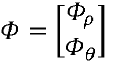
- ⁇ ⁇ ⁇ ⁇ ⁇ is a binary matrix of size 64 x (128 x 128), which contains two components of size 32 x (128 x 128), corresponding to 32 radial and 32 angular power bins.
- the event-driven feature extractor 130 computes the value of y(t) at the end of every sensor event packet that contains on the order of 100 to 200 events.
- eSVM event-driven support vector classifier
- the classifier 140 computes the value of z(t) at the end of every sensor event packet that occurs at least ⁇ t min since the last classification.
- TABLE 1 specifies mathematical description of the input/output objects to and from the modules/components of the system.
- TABLES 2 and 3 provide the constant and state variables used for the event-driven short-time spatial DFT.
- TABLE 4 is pseudo-code for a single iteration of the detection system during which an event packet of length K is processed from the DVS.
- TABLE 3 State variable Type Dimension Description t real K ⁇ 1 Event packet time stamp vector p -1,1 K ⁇ 1 Event packet polarity vector ⁇ 1,...,128 K ⁇ 1 Event packet horizontal coordinate vector v 1,...,128 K ⁇ 1 Event packet vertical coordinate vector X complex 128 ⁇ 128 Short-time spatial DFT matrix y real 64 ⁇ 1 Feature vector z categorical 1 ⁇ 1 Class label t current real 1 ⁇ 1 Current event time t last real 1 ⁇ 1 Last event time t classify real 1 ⁇ 1 Last classifiication time
- an event based processing system may use a sensor, such as a dynamic vision sensor (DVS), to detect moving objects, such as people or cars.
- the sensor such as the dynamic vision sensor, detects the change in luminance such that at least one event may be an indication that the luminance has changed at a particular location.
- the event-driven object detection system may classify the detected objects in real time based on prior training.
- the event based processing system may output one or more detected events.
- events may be referred to as pixel events.
- a frame based processing system classifies objects detected in a frame, such as a picture.
- a frame may be processed by a frame based processing system, such as a Support Vector Machine (SVM) classifier.
- SVM Support Vector Machine
- the events output by the event based object detection system may not be processed by a frame based processing system.
- the frame based processing system may be referred to as a frame based classifier.
- a frame based processing system may be specified for an event based object detection system. Because the desired input of the frame based processing system may not be compatible with the output of the event based object detection system, an interface may be specified to convert event based outputs to a frame input. The converting of the events may be performed in real time as events are received or when a specific number of events have been received.
- the event based object detection system may be referred to as the event based system or the event based processing system.
- a timing interface is specified to generate a frame by aggregating events received over a predetermined time. Furthermore, the aggregated events are input into the frame based classifier from the interface. The specific time period may be dynamically modified based on desired results and/or processing load.
- an event number interface is specified to generate a frame by aggregating a specific number of events into a frame. The specific number of events may be dynamically modified based on desired results and/or processing load.
- the interface is dynamically selected. That is, the interface may dynamically switch between aggregating events for a specific time period into the frame and aggregating a specific number of events into the frame, and vice versa. The switching may be initiated based on desired results and/or processing load.
- aspects of the present disclosure are not limited to image processing and may also be applied to other sensors, such as audio sensors.
- audio frequencies or other audio characteristics may be detected by an event based object detection system and may be input to a frame based processing system or an equivalent type of processing system.
- a filter may be defined between the output of the event based object detection system and the input to the interface.
- the filter may be specified to filter (i.e., drop) specific events, such as events from specific areas that are not important, events from areas that produce an increased amount of noise, and/or events that satisfy other conditions.
- the downstream processing block determines that a number of events from a specific region have exceeded a threshold.
- the filtering of events to drop subsequent events from the specific region may be specified by the downstream processing block.
- the region may refer to a spatial area that produces events and/or a specific event generator, such as a specific vehicle that generates events.
- the filter is not limited to filtering events that are visual and may also filter audio, temporal, or other events.
- the filter may drop events occurring in a specific spectral frequency, such as an audio frequency, and/or the filter may drop events occurring at a specific time period. Additionally, events from a specific region or all events may be dropped when the processing load of the system exceeds a threshold and/or when another condition is satisfied.
- a specific area may have produced events that are greater than a threshold. Therefore, because the system has already received a specific number of events, the system may no longer desire to receive additional events from a specific region.
- the filter may be specified to filter events from specific regions.
- a downstream processing block such as the frame based classifier, may desire to only classify events from one or more specific regions. Therefore, the filter may filter all or some events that are different from desired region(s).
- FIGURE 2 illustrates an example of an interface according to an aspect of the present disclosure.
- an event may be generated at an event generator 202.
- the event generator may be a sensor, such as a camera, or other device that processes events.
- the events may be events generated from pixels received at a camera.
- the events are input to the interface 204.
- the interface may dynamically select between a timing interface and an event number interface to generate a frame.
- the generated frame is output to a classifier 206, such as frame based processing system.
- an optional filter 208 may be defined between the event generator 202 and the interface 204. As previously discussed, the filter 208 may be used to filter all events or specific events.
- FIGURE 3 illustrates a flow diagram 300 for interfacing an event based system with a frame based processing system in accordance with aspects of the present disclosure.
- the system converts multiple events into a frame.
- the events may be generated from an event sensor.
- the system inputs the frame into the frame based processing system, such as a classifier.
- FIGURE 4 is a diagram illustrating an example of a hardware implementation for an apparatus 400 employing a processing system 414 for interfacing an event based system with a frame based system.
- the processing system 414 may be implemented with a bus architecture, represented generally by the bus 424.
- the bus 424 may include any number of interconnecting buses and bridges depending on the specific application of the processing system 414 and the overall design constraints.
- the bus 424 links together various circuits including one or more processors and/or hardware modules, represented by the processor 422 the modules 402, 404, and the computer-readable medium 426.
- the bus 424 may also link various other circuits such as timing sources, peripherals, voltage regulators, and power management circuits, which are well known in the art, and therefore, will not be described any further.
- the apparatus includes a processing system 414 coupled to a transceiver 430.
- the transceiver 430 is coupled to one or more antennas 420.
- the transceiver 430 enables communicating with various other apparatus over a transmission medium.
- the processing system 414 includes a processor 422 coupled to a computer-readable medium 426.
- the processor 422 is responsible for general processing, including the execution of software stored on the computer-readable medium 426.
- the software when executed by the processor 422, causes the processing system 414 to perform the various functions described for any particular apparatus.
- the computer-readable medium 426 may also be used for storing data that is manipulated by the processor 422 when executing software.
- the processing system 414 includes a converting module 402 for converting events, generated from an event sensor, into a frame.
- the processing system 414 also includes an inputting module 404 for inputting the frame into the frame based processing system.
- the modules may be software modules running in the processor 422, resident/stored in the computer-readable medium 426, one or more hardware modules coupled to the processor 422, or some combination thereof.
- an interface 204 is configured for interfacing an event based processing system with a frame based processing system.
- the interface 204 may include means for converting and means for inputting.
- the converting means may be the converting module 402 configured to perform the functions recited by the converting means.
- the interface 204 is also configured to include a means for inputting.
- the inputting means may be the inputting module 404 configured to perform the functions recited by the inputting means.
- the aforementioned means may be any module or any apparatus configured to perform the functions recited by the aforementioned means.
- the various operations of methods described above may be performed by any suitable means capable of performing the corresponding functions.
- the means may include various hardware and/or software component(s) and/or module(s), including, but not limited to, a circuit, an application specific integrated circuit (ASIC), or processor.
- ASIC application specific integrated circuit
- determining encompasses a wide variety of actions. For example, “determining” may include calculating, computing, processing, deriving, investigating, looking up (e.g., looking up in a table, a database or another data structure), ascertaining and the like. Additionally, “determining” may include receiving (e.g., receiving information), accessing (e.g., accessing data in a memory) and the like. Furthermore, “determining” may include resolving, selecting, choosing, establishing and the like.
- a phrase referring to "at least one of' a list of items refers to any combination of those items, including single members.
- "at least one of: a, b, or c” is intended to cover: a, b, c, a-b, a-c, b-c, and a-b-c.
- DSP digital signal processor
- ASIC application specific integrated circuit
- FPGA field programmable gate array signal
- PLD programmable logic device
- a general-purpose processor may be a microprocessor, but in the alternative, the processor may be any commercially available processor, controller, microcontroller or state machine.
- a processor may also be implemented as a combination of computing devices, e.g., a combination of a DSP and a microprocessor, a plurality of microprocessors, one or more microprocessors in conjunction with a DSP core, or any other such configuration.
- a software module may reside in any form of storage medium that is known in the art. Some examples of storage media that may be used include random access memory (RAM), read only memory (ROM), flash memory, erasable programmable read-only memory (EPROM), electrically erasable programmable read-only memory (EEPROM), registers, a hard disk, a removable disk, a CD-ROM and so forth.
- RAM random access memory
- ROM read only memory
- EPROM erasable programmable read-only memory
- EEPROM electrically erasable programmable read-only memory
- registers a hard disk, a removable disk, a CD-ROM and so forth.
- a software module may comprise a single instruction, or many instructions, and may be distributed over several different code segments, among different programs, and across multiple storage media.
- a storage medium may be coupled to a processor such that the processor can read information from, and write information to, the storage medium. In the alternative, the storage medium may be integral to the processor.
- an example hardware configuration may comprise a processing system in a device.
- the processing system may be implemented with a bus architecture.
- the bus may include any number of interconnecting buses and bridges depending on the specific application of the processing system and the overall design constraints.
- the bus may link together various circuits including a processor, machine-readable media, and a bus interface.
- the bus interface may be used to connect a network adapter, among other things, to the processing system via the bus.
- the network adapter may be used to implement signal processing functions.
- a user interface e.g., keypad, display, mouse, joystick, etc.
- the bus may also link various other circuits such as timing sources, peripherals, voltage regulators, power management circuits, and the like, which are well known in the art, and therefore, will not be described any further.
- the processor may be responsible for managing the bus and general processing, including the execution of software stored on the machine-readable media.
- the processor may be implemented with one or more general-purpose and/or special-purpose processors. Examples include microprocessors, microcontrollers, DSP processors, and other circuitry that can execute software.
- Software shall be construed broadly to mean instructions, data, or any combination thereof, whether referred to as software, firmware, middleware, microcode, hardware description language, or otherwise.
- Machine-readable media may include, by way of example, random access memory (RAM), flash memory, read only memory (ROM), programmable read-only memory (PROM), erasable programmable read-only memory (EPROM), electrically erasable programmable Read-only memory (EEPROM), registers, magnetic disks, optical disks, hard drives, or any other suitable storage medium, or any combination thereof.
- RAM random access memory
- ROM read only memory
- PROM programmable read-only memory
- EPROM erasable programmable read-only memory
- EEPROM electrically erasable programmable Read-only memory
- registers magnetic disks, optical disks, hard drives, or any other suitable storage medium, or any combination thereof.
- the machine-readable media may be embodied in a computer-program product.
- the computer-program product may comprise packaging materials.
- the machine-readable media may be part of the processing system separate from the processor.
- the machine-readable media, or any portion thereof may be external to the processing system.
- the machine-readable media may include a transmission line, a carrier wave modulated by data, and/or a computer product separate from the device, all which may be accessed by the processor through the bus interface.
- the machine-readable media, or any portion thereof may be integrated into the processor, such as the case may be with cache and/or general register files.
- the various components discussed may be described as having a specific location, such as a local component, they may also be configured in various ways, such as certain components being configured as part of a distributed computing system.
- the processing system may be configured as a general-purpose processing system with one or more microprocessors providing the processor functionality and external memory providing at least a portion of the machine-readable media, all linked together with other supporting circuitry through an external bus architecture.
- the processing system may comprise one or more neuromorphic processors for implementing the neuron models and models of neural systems described herein.
- the processing system may be implemented with an application specific integrated circuit (ASIC) with the processor, the bus interface, the user interface, supporting circuitry, and at least a portion of the machine-readable media integrated into a single chip, or with one or more field programmable gate arrays (FPGAs), programmable logic devices (PLDs), controllers, state machines, gated logic, discrete hardware components, or any other suitable circuitry, or any combination of circuits that can perform the various functionality described throughout this disclosure.
- ASIC application specific integrated circuit
- FPGAs field programmable gate arrays
- PLDs programmable logic devices
- controllers state machines, gated logic, discrete hardware components, or any other suitable circuitry, or any combination of circuits that can perform the various functionality described throughout this disclosure.
- the machine-readable media may comprise a number of software modules.
- the software modules include instructions that, when executed by the processor, cause the processing system to perform various functions.
- the software modules may include a transmission module and a receiving module.
- Each software module may reside in a single storage device or be distributed across multiple storage devices.
- a software module may be loaded into RAM from a hard drive when a triggering event occurs.
- the processor may load some of the instructions into cache to increase access speed.
- One or more cache lines may then be loaded into a general register file for execution by the processor.
- Computer-readable media include both computer storage media and communication media including any medium that facilitates transfer of a computer program from one place to another.
- a storage medium may be any available medium that can be accessed by a computer.
- such computer-readable media can comprise RAM, ROM, EEPROM, CD-ROM or other optical disk storage, magnetic disk storage or other magnetic storage devices, or any other medium that can be used to carry or store desired program code in the form of instructions or data structures and that can be accessed by a computer.
- any connection is properly termed a computer-readable medium.
- Disk and disc include compact disc (CD), laser disc, optical disc, digital versatile disc (DVD), floppy disk, and Blu-ray® disc where disks usually reproduce data magnetically, while discs reproduce data optically with lasers.
- computer-readable media may comprise non-transitory computer-readable media (e.g., tangible media).
- computer-readable media may comprise transitory computer- readable media (e.g., a signal). Combinations of the above should also be included within the scope of computer-readable media.
- certain aspects may comprise a computer program product for performing the operations presented herein.
- a computer program product may comprise a computer-readable medium having instructions stored (and/or encoded) thereon, the instructions being executable by one or more processors to perform the operations described herein.
- the computer program product may include packaging material.
- modules and/or other appropriate means for performing the methods and techniques described herein can be downloaded and/or otherwise obtained by a user terminal and/or base station as applicable.
- a user terminal and/or base station can be coupled to a server to facilitate the transfer of means for performing the methods described herein.
- various methods described herein can be provided via storage means (e.g., RAM, ROM, a physical storage medium such as a compact disc (CD) or floppy disk, etc.), such that a user terminal and/or base station can obtain the various methods upon coupling or providing the storage means to the device.
- storage means e.g., RAM, ROM, a physical storage medium such as a compact disc (CD) or floppy disk, etc.
- CD compact disc
- floppy disk etc.
- any other suitable technique for providing the methods and techniques described herein to a device can be utilized.
Landscapes
- Engineering & Computer Science (AREA)
- Theoretical Computer Science (AREA)
- Physics & Mathematics (AREA)
- General Physics & Mathematics (AREA)
- Multimedia (AREA)
- Data Mining & Analysis (AREA)
- Bioinformatics & Cheminformatics (AREA)
- Evolutionary Biology (AREA)
- Evolutionary Computation (AREA)
- Computer Vision & Pattern Recognition (AREA)
- General Engineering & Computer Science (AREA)
- Bioinformatics & Computational Biology (AREA)
- Artificial Intelligence (AREA)
- Life Sciences & Earth Sciences (AREA)
- Image Analysis (AREA)
- Image Processing (AREA)
Description
- Certain aspects of the present disclosure generally relate to neural system engineering and, more particularly, to systems and methods for interfacing an event based system with a frame based processing system.
- An event-driven object detection system may use a sensor, such as a dynamic vision sensor (DVS), to detect moving objects, such as faces or cars. Furthermore, the event-driven object detection system may classify the detected objects in real time based on prior training. In some cases, it is desirable to interface an event based system with a frame based processing system to process the detected events.
- "Address-Event Imagers for Sensor Networks: Evaluation and Modeling" by Teixeira T. et. al. In: Information Processing in Sensor Networks, 2006, International Coference of Nashvile, pp 458-466 discusses address-event image sensors as a solution to, amongst other things, privacy issues raised by the deployment of cameras in everyday environments. "Vision without Frames: A Semiotic Paradigm of Event Based Computer Vision" by Benosman R. In: Biosemiotics, 2010, Vol. 3, No. 1, pp. 1-16 discusses methods of implementation of an event-based processing system. "A 128128 120 dB 15 s Latency Asynchronous Temporal Contrast Vision Sensor" by Litchtsteiner P. et. al. In: Journal of Solid-State Circuits, 2008, Vol. 43, No. 2, pp. 566-576 discusses vision sensor whose pixels respond asynchronously to relative changes in intensity. "Ground Truth Evaluation for Event-Based Silicon Retina Stereo Data" by Kogler J. et. al. In: Conference on Computer Vision and Pattern Recognition Workshops, 2003, pp. 649-656 discusses means of mitigating stereo vision problems in event-based processing systems.
-
EP 2 574 511 A1 discusses event-based camera detection systems and analysis with novel algorithms to facilitate road surface condition analysis. - In one aspect of the present disclosure, a method for interfacing an event based processing system with a frame based processing system is disclosed as set out in claim 1. The method includes converting multiple events into a frame. In one configuration, the events are generated from an event sensor. The method also includes inputting the frame into the frame based processing system.
- Another aspect of the present disclosure is directed to an apparatus including means for converting multiple events into a frame as set out in claim 3. In one configuration, the events are generated from an event sensor. The apparatus also includes means for inputting the frame into the frame based processing system.
- In another aspect of the present disclosure, a computer program product for interfacing an event based processing system with a frame based processing system is disclosed as set out in claim 5. The computer program product has a non-transitory computer-readable medium with non-transitory program code recorded thereon. The program code is executed by a processor and includes program code to convert multiple events into a frame. In one configuration, the events are generated from an event sensor. The program code also includes program code to input the frame into the frame based processing system.
- Additional features and advantages of the disclosure will be described below. Other aspects of the present invention can be found in the dependent claims. The novel features, which are believed to be characteristic of the disclosure, both as to its organization and method of operation, together with further objects and advantages, will be better understood from the following description when considered in connection with the accompanying figures.
- The features, nature, and advantages of the present disclosure will become more apparent from the detailed description set forth below when taken in conjunction with the drawings in which like reference characters identify correspondingly throughout.
-
FIGURE 1 illustrates an example of components of an event-driven object-detection system in accordance with certain aspects of the present disclosure. -
FIGURE 2 illustrates an example of an interface between an event based processing system and a frame based processing system. -
FIGURE 3 is a flow diagram illustrating a method for interfacing an event based processing system with a frame based processing system in accordance with an aspect of the present disclosure. -
FIGURE 4 is a block diagram illustrating different modules/means/components in an exemplary apparatus. - The detailed description includes specific details for the purpose of providing a thorough understanding of the various concepts. However, it will be apparent to those skilled in the art that these concepts may be practiced without these specific details. In some instances, well-known structures and components are shown in block diagram form in order to avoid obscuring such concepts.
- The word "exemplary" is used herein to mean "serving as an example, instance, or illustration." Any aspect described herein as "exemplary" is not necessarily to be construed as preferred or advantageous over other aspects.
- An event-driven object detection system may use a sensor, such as a dynamic vision sensor (DVS), to detect moving objects, such as faces or cars. Furthermore, the event-driven object detection system may classify the detected objects in real time based on prior training. The computations in the system may be triggered by sensor events. The event-driven object detection system may be referred to as the detection system.
- According to aspects of the present disclosure, a detections system may process an image when an event is generated. That is, the detection system does not perform processing when events are not output from the sensor. Moreover, the processing load scales linearly with the sensor event rate.
- The
detection system 100 comprises various modules for processing data. As an example, as shown inFIGURE 1 , the detection system may include asensor 110, such as a dynamic vision sensor, an event-driven sort time spatial discrete Fourier transformer (DFT) 120, an event-drivenfeature extractor 130, and aclassifier 140. - In one configuration, the
sensor 110 is configured to detect events. Specifically, the events may be generated from a change in intensity of a detected pixel. For example, thesensor 110 may be a DVS128 sensor from iniLabs. The sensor array may have a size of N x N (N = 128) of which each pixel is a level-crossing sampler of log-luminance in time. The temporal resolution of the pixel is on the order of ten micro seconds. The output of the sensor may be a polarized, coordinate-addressed event train {(tk; pk; uk; vk)}, where tk's and pk's are time stamps and polarities of events and (µk; vk) are the pixel coordinates of event tk. Here tk ∈ R, pk ∈ {-1,1} and µk, vk ∈ {1, ...,128}. - The pixel response functions may be defined as:


- The event-driven spatial DFT (eSTsDFT) 120 receives an event train {(tk; pk; µk; vk)} as an input and outputs a real-time complex N x N (N = 128) matrix of spatial DFT:

- Here


- Furthermore, w(-t) = θ(t) exp (- ω 0 t) is an exponential short-time window function. The
eSTsDFT 120 computes the value of X̃(t) at each sensor event {tk}. - The event-drive feature extractor (eFE) 130 reduces the dimensionality of the output of the
eSTsDFT 120 from N x N x 2 (N = 128) to L = 64 (i.e., from 128 complex numbers to 64 real numbers). Specifically, the L features are binned instantaneous spectral power of X̃(t), y(t) = ϕ(X̃ * (t)X̃(t)) where * is the conjugate transpose and ϕ () is a log-linear transformation function, which is computed as follows. - X̃ * X̃ may be written as a 128 x 128 dimensional vector x and the linear function ϕ(), may be expressed as a matrix multiplication followed by a logarithm y = log(Φx), where
- The event-driven
feature extractor 130 computes the value of y(t) at the end of every sensor event packet that contains on the order of 100 to 200 events. - The
classifier 140, such as an event-driven support vector classifier (eSVM), computes a time-varying class label function z(t) based on the real-time feature vector y(t) extracted by theeFE 130, i.e., z(t) = ψ(y(t)), by virtue of a support vector machine with a Gaussian radial basis function (RBF) as kernels. - The
classifier 140 computes the value of z(t) at the end of every sensor event packet that occurs at least Δtmin since the last classification. As described below, TABLE 1 specifies mathematical description of the input/output objects to and from the modules/components of the system.
- TABLES 2 and 3 provide the constant and state variables used for the event-driven short-time spatial DFT. TABLE 4 is pseudo-code for a single iteration of the detection system during which an event packet of length K is processed from the DVS.

TABLE 3 State variable Type Dimension Description t real K × 1 Event packet time stamp vector p -1,1 K × 1 Event packet polarity vector µ 1,...,128 K × 1 Event packet horizontal coordinate vector v 1,...,128 K × 1 Event packet vertical coordinate vector X complex 128 × 128 Short-time spatial DFT matrix y real 64 × 1 Feature vector z categorical 1 × 1 Class label t current real 1 × 1 Current event time t last real 1 × 1 Last event time t classify real 1 × 1 Last classifiication time 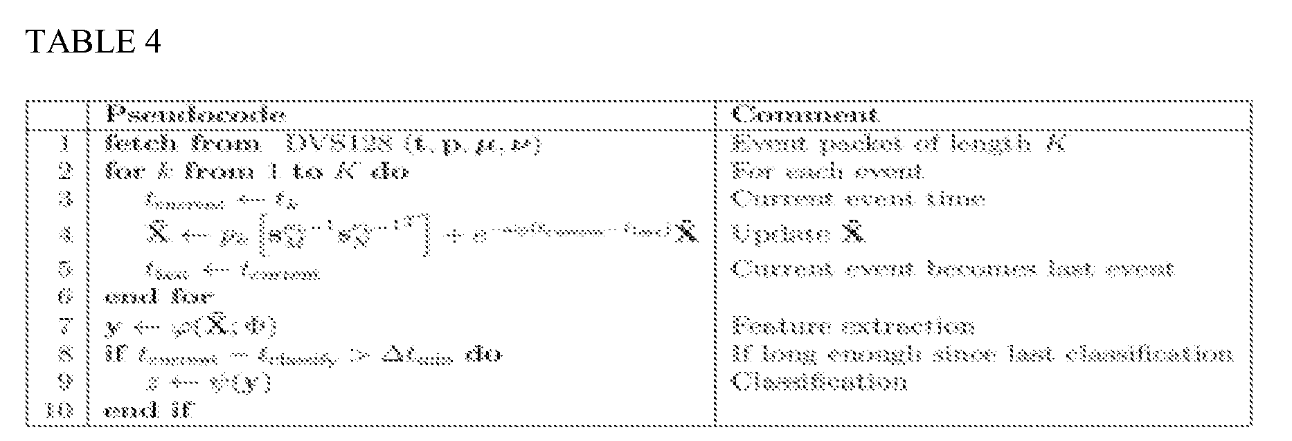
- As previously discussed, an event based processing system may use a sensor, such as a dynamic vision sensor (DVS), to detect moving objects, such as people or cars. For example, the sensor, such as the dynamic vision sensor, detects the change in luminance such that at least one event may be an indication that the luminance has changed at a particular location. Furthermore, the event-driven object detection system may classify the detected objects in real time based on prior training. Thus, the event based processing system may output one or more detected events. In the present application, events may be referred to as pixel events.
- Furthermore, a frame based processing system classifies objects detected in a frame, such as a picture. A frame may be processed by a frame based processing system, such as a Support Vector Machine (SVM) classifier. In a conventional system, the events output by the event based object detection system may not be processed by a frame based processing system. The frame based processing system may be referred to as a frame based classifier.
- Still, in some cases, a frame based processing system may be specified for an event based object detection system. Because the desired input of the frame based processing system may not be compatible with the output of the event based object detection system, an interface may be specified to convert event based outputs to a frame input. The converting of the events may be performed in real time as events are received or when a specific number of events have been received. The event based object detection system may be referred to as the event based system or the event based processing system.
- In one configuration, a timing interface is specified to generate a frame by aggregating events received over a predetermined time. Furthermore, the aggregated events are input into the frame based classifier from the interface. The specific time period may be dynamically modified based on desired results and/or processing load. In another configuration, an event number interface is specified to generate a frame by aggregating a specific number of events into a frame. The specific number of events may be dynamically modified based on desired results and/or processing load.
- Furthermore, in one configuration, the interface is dynamically selected. That is, the interface may dynamically switch between aggregating events for a specific time period into the frame and aggregating a specific number of events into the frame, and vice versa. The switching may be initiated based on desired results and/or processing load.
- It should be noted that aspects of the present disclosure are not limited to image processing and may also be applied to other sensors, such as audio sensors. For example, audio frequencies or other audio characteristics may be detected by an event based object detection system and may be input to a frame based processing system or an equivalent type of processing system.
- Additionally, or alternatively, in one configuration, a filter may be defined between the output of the event based object detection system and the input to the interface. The filter may be specified to filter (i.e., drop) specific events, such as events from specific areas that are not important, events from areas that produce an increased amount of noise, and/or events that satisfy other conditions. In one configuration, the downstream processing block determines that a number of events from a specific region have exceeded a threshold. Thus, the filtering of events to drop subsequent events from the specific region may be specified by the downstream processing block. The region may refer to a spatial area that produces events and/or a specific event generator, such as a specific vehicle that generates events.
- It should be noted that the filter is not limited to filtering events that are visual and may also filter audio, temporal, or other events. For example, the filter may drop events occurring in a specific spectral frequency, such as an audio frequency, and/or the filter may drop events occurring at a specific time period. Additionally, events from a specific region or all events may be dropped when the processing load of the system exceeds a threshold and/or when another condition is satisfied.
- For example, a specific area may have produced events that are greater than a threshold. Therefore, because the system has already received a specific number of events, the system may no longer desire to receive additional events from a specific region. Thus, the filter may be specified to filter events from specific regions. As another example, a downstream processing block, such as the frame based classifier, may desire to only classify events from one or more specific regions. Therefore, the filter may filter all or some events that are different from desired region(s).
-
FIGURE 2 illustrates an example of an interface according to an aspect of the present disclosure. As shown inFIGURE 2 , an event may be generated at anevent generator 202. The event generator may be a sensor, such as a camera, or other device that processes events. For example, the events may be events generated from pixels received at a camera. Furthermore, the events are input to theinterface 204. As previously discussed, the interface may dynamically select between a timing interface and an event number interface to generate a frame. Moreover, the generated frame is output to aclassifier 206, such as frame based processing system. Additionally, as shown inFIGURE 2 , anoptional filter 208 may be defined between theevent generator 202 and theinterface 204. As previously discussed, thefilter 208 may be used to filter all events or specific events. -
FIGURE 3 illustrates a flow diagram 300 for interfacing an event based system with a frame based processing system in accordance with aspects of the present disclosure. As show inFIGURE 3 , atblock 302, the system converts multiple events into a frame. The events may be generated from an event sensor. Furthermore, atblock 304, the system inputs the frame into the frame based processing system, such as a classifier. -
FIGURE 4 is a diagram illustrating an example of a hardware implementation for anapparatus 400 employing aprocessing system 414 for interfacing an event based system with a frame based system. Theprocessing system 414 may be implemented with a bus architecture, represented generally by thebus 424. Thebus 424 may include any number of interconnecting buses and bridges depending on the specific application of theprocessing system 414 and the overall design constraints. Thebus 424 links together various circuits including one or more processors and/or hardware modules, represented by theprocessor 422 themodules readable medium 426. Thebus 424 may also link various other circuits such as timing sources, peripherals, voltage regulators, and power management circuits, which are well known in the art, and therefore, will not be described any further. - The apparatus includes a
processing system 414 coupled to atransceiver 430. Thetransceiver 430 is coupled to one ormore antennas 420. Thetransceiver 430 enables communicating with various other apparatus over a transmission medium. Theprocessing system 414 includes aprocessor 422 coupled to a computer-readable medium 426. Theprocessor 422 is responsible for general processing, including the execution of software stored on the computer-readable medium 426. The software, when executed by theprocessor 422, causes theprocessing system 414 to perform the various functions described for any particular apparatus. The computer-readable medium 426 may also be used for storing data that is manipulated by theprocessor 422 when executing software. - The
processing system 414 includes a convertingmodule 402 for converting events, generated from an event sensor, into a frame. Theprocessing system 414 also includes aninputting module 404 for inputting the frame into the frame based processing system. The modules may be software modules running in theprocessor 422, resident/stored in the computer-readable medium 426, one or more hardware modules coupled to theprocessor 422, or some combination thereof. - In one configuration, an
interface 204 is configured for interfacing an event based processing system with a frame based processing system. Theinterface 204 may include means for converting and means for inputting. In one aspect, the converting means may be the convertingmodule 402 configured to perform the functions recited by the converting means. Theinterface 204 is also configured to include a means for inputting. In one aspect, the inputting means may be the inputtingmodule 404 configured to perform the functions recited by the inputting means. In another aspect, the aforementioned means may be any module or any apparatus configured to perform the functions recited by the aforementioned means. - The various operations of methods described above may be performed by any suitable means capable of performing the corresponding functions. The means may include various hardware and/or software component(s) and/or module(s), including, but not limited to, a circuit, an application specific integrated circuit (ASIC), or processor. Generally, where there are operations illustrated in the figures, those operations may have corresponding counterpart means-plus-function components with similar numbering.
- As used herein, the term "determining" encompasses a wide variety of actions. For example, "determining" may include calculating, computing, processing, deriving, investigating, looking up (e.g., looking up in a table, a database or another data structure), ascertaining and the like. Additionally, "determining" may include receiving (e.g., receiving information), accessing (e.g., accessing data in a memory) and the like. Furthermore, "determining" may include resolving, selecting, choosing, establishing and the like.
- As used herein, a phrase referring to "at least one of' a list of items refers to any combination of those items, including single members. As an example, "at least one of: a, b, or c" is intended to cover: a, b, c, a-b, a-c, b-c, and a-b-c.
- The various illustrative logical blocks, modules and circuits described in connection with the present disclosure may be implemented or performed with a general purpose processor, a digital signal processor (DSP), an application specific integrated circuit (ASIC), a field programmable gate array signal (FPGA) or other programmable logic device (PLD), discrete gate or transistor logic, discrete hardware components or any combination thereof designed to perform the functions described herein. A general-purpose processor may be a microprocessor, but in the alternative, the processor may be any commercially available processor, controller, microcontroller or state machine. A processor may also be implemented as a combination of computing devices, e.g., a combination of a DSP and a microprocessor, a plurality of microprocessors, one or more microprocessors in conjunction with a DSP core, or any other such configuration.
- The steps of a method or algorithm described in connection with the present disclosure may be embodied directly in hardware, in a software module executed by a processor, or in a combination of the two. A software module may reside in any form of storage medium that is known in the art. Some examples of storage media that may be used include random access memory (RAM), read only memory (ROM), flash memory, erasable programmable read-only memory (EPROM), electrically erasable programmable read-only memory (EEPROM), registers, a hard disk, a removable disk, a CD-ROM and so forth. A software module may comprise a single instruction, or many instructions, and may be distributed over several different code segments, among different programs, and across multiple storage media. A storage medium may be coupled to a processor such that the processor can read information from, and write information to, the storage medium. In the alternative, the storage medium may be integral to the processor.
- The functions described may be implemented in hardware, software, firmware, or any combination thereof. If implemented in hardware, an example hardware configuration may comprise a processing system in a device. The processing system may be implemented with a bus architecture. The bus may include any number of interconnecting buses and bridges depending on the specific application of the processing system and the overall design constraints. The bus may link together various circuits including a processor, machine-readable media, and a bus interface. The bus interface may be used to connect a network adapter, among other things, to the processing system via the bus. The network adapter may be used to implement signal processing functions. For certain aspects, a user interface (e.g., keypad, display, mouse, joystick, etc.) may also be connected to the bus. The bus may also link various other circuits such as timing sources, peripherals, voltage regulators, power management circuits, and the like, which are well known in the art, and therefore, will not be described any further.
- The processor may be responsible for managing the bus and general processing, including the execution of software stored on the machine-readable media. The processor may be implemented with one or more general-purpose and/or special-purpose processors. Examples include microprocessors, microcontrollers, DSP processors, and other circuitry that can execute software. Software shall be construed broadly to mean instructions, data, or any combination thereof, whether referred to as software, firmware, middleware, microcode, hardware description language, or otherwise. Machine-readable media may include, by way of example, random access memory (RAM), flash memory, read only memory (ROM), programmable read-only memory (PROM), erasable programmable read-only memory (EPROM), electrically erasable programmable Read-only memory (EEPROM), registers, magnetic disks, optical disks, hard drives, or any other suitable storage medium, or any combination thereof. The machine-readable media may be embodied in a computer-program product. The computer-program product may comprise packaging materials.
- In a hardware implementation, the machine-readable media may be part of the processing system separate from the processor. However, as those skilled in the art will readily appreciate, the machine-readable media, or any portion thereof, may be external to the processing system. By way of example, the machine-readable media may include a transmission line, a carrier wave modulated by data, and/or a computer product separate from the device, all which may be accessed by the processor through the bus interface. Alternatively, or in addition, the machine-readable media, or any portion thereof, may be integrated into the processor, such as the case may be with cache and/or general register files. Although the various components discussed may be described as having a specific location, such as a local component, they may also be configured in various ways, such as certain components being configured as part of a distributed computing system.
- The processing system may be configured as a general-purpose processing system with one or more microprocessors providing the processor functionality and external memory providing at least a portion of the machine-readable media, all linked together with other supporting circuitry through an external bus architecture. Alternatively, the processing system may comprise one or more neuromorphic processors for implementing the neuron models and models of neural systems described herein. As another alternative, the processing system may be implemented with an application specific integrated circuit (ASIC) with the processor, the bus interface, the user interface, supporting circuitry, and at least a portion of the machine-readable media integrated into a single chip, or with one or more field programmable gate arrays (FPGAs), programmable logic devices (PLDs), controllers, state machines, gated logic, discrete hardware components, or any other suitable circuitry, or any combination of circuits that can perform the various functionality described throughout this disclosure. Those skilled in the art will recognize how best to implement the described functionality for the processing system depending on the particular application and the overall design constraints imposed on the overall system.
- The machine-readable media may comprise a number of software modules. The software modules include instructions that, when executed by the processor, cause the processing system to perform various functions. The software modules may include a transmission module and a receiving module. Each software module may reside in a single storage device or be distributed across multiple storage devices. By way of example, a software module may be loaded into RAM from a hard drive when a triggering event occurs. During execution of the software module, the processor may load some of the instructions into cache to increase access speed. One or more cache lines may then be loaded into a general register file for execution by the processor. When referring to the functionality of a software module below, it will be understood that such functionality is implemented by the processor when executing instructions from that software module.
- If implemented in software, the functions may be stored or transmitted over as one or more instructions or code on a computer-readable medium. Computer-readable media include both computer storage media and communication media including any medium that facilitates transfer of a computer program from one place to another. A storage medium may be any available medium that can be accessed by a computer. By way of example, and not limitation, such computer-readable media can comprise RAM, ROM, EEPROM, CD-ROM or other optical disk storage, magnetic disk storage or other magnetic storage devices, or any other medium that can be used to carry or store desired program code in the form of instructions or data structures and that can be accessed by a computer. Also, any connection is properly termed a computer-readable medium. For example, if the software is transmitted from a website, server, or other remote source using a coaxial cable, fiber optic cable, twisted pair, digital subscriber line (DSL), or wireless technologies such as infrared (IR), radio, and microwave, then the coaxial cable, fiber optic cable, twisted pair, DSL, or wireless technologies such as infrared, radio, and microwave are included in the definition of medium. Disk and disc, as used herein, include compact disc (CD), laser disc, optical disc, digital versatile disc (DVD), floppy disk, and Blu-ray® disc where disks usually reproduce data magnetically, while discs reproduce data optically with lasers. Thus, in some aspects computer-readable media may comprise non-transitory computer-readable media (e.g., tangible media). In addition, for other aspects computer-readable media may comprise transitory computer- readable media (e.g., a signal). Combinations of the above should also be included within the scope of computer-readable media.
- Thus, certain aspects may comprise a computer program product for performing the operations presented herein. For example, such a computer program product may comprise a computer-readable medium having instructions stored (and/or encoded) thereon, the instructions being executable by one or more processors to perform the operations described herein. For certain aspects, the computer program product may include packaging material.
- Further, it should be appreciated that modules and/or other appropriate means for performing the methods and techniques described herein can be downloaded and/or otherwise obtained by a user terminal and/or base station as applicable. For example, such a device can be coupled to a server to facilitate the transfer of means for performing the methods described herein. Alternatively, various methods described herein can be provided via storage means (e.g., RAM, ROM, a physical storage medium such as a compact disc (CD) or floppy disk, etc.), such that a user terminal and/or base station can obtain the various methods upon coupling or providing the storage means to the device. Moreover, any other suitable technique for providing the methods and techniques described herein to a device can be utilized.
Claims (5)
- A method of interfacing an event based processing system with a frame based processing system, comprising:receiving at a filter (208) an event stream (202) generated from an event sensor (110), wherein each event in the event stream is generated from a change in intensity of a detected pixel, and wherein each event is associated with a time stamp and pixel coordinates;removing, at the filter that receives the event stream generated from the event sensor, an event that is generated in a specific region of a sensor array of the event sensor, wherein the event is removed when a number of already received events generated in the specific region has exceeded a threshold;converting a plurality of events, received from the event stream output from the filter into a frame, wherein the plurality of events are aggregated for a specific time period into the frame, or a specific number of events of the plurality of events are aggregated into the frame; andinputting the frame into the frame based processing system (206).
- The method of claim 1, in which at least one event of the plurality of events is an indication from a vision sensor that a luminance has changed at a particular location.
- An apparatus for interfacing an event based processing system with a frame based processing system, the apparatus comprising:means for receiving at a filter (208) an event stream (202) generated from an event sensor (110), wherein each event in the event stream is generated from a change in intensity of a detected pixel, and wherein each event is associated with a time stamp and pixel coordinatesmeans for removing, at the filter that receives the event stream generated from the event sensor, an event from the event stream generated in a specific region of a sensor array of the event sensor, wherein the event is removed when a number of already received events generated in the specific region has exceeded a threshold;means for converting a plurality of events, received from the event stream output from the filter, into a frame, wherein the plurality of events are aggregated for a specific time period into the frame or a specific number of events of the plurality of events are aggregated into the frame; andmeans for inputting the frame into the frame based processing system (206).
- The apparatus of claim 3, in which at least one event of the plurality of events is an indication from a vision sensor that a luminance has changed at a particular location.
- A non-transitory computer-readable medium having program code recorded thereon for interfacing an event based processing system with a frame based processing system, the program code being executed by a processor and comprising: program code to perform the method of any of claims 1 to 2.
Applications Claiming Priority (3)
| Application Number | Priority Date | Filing Date | Title |
|---|---|---|---|
| US201462051145P | 2014-09-16 | 2014-09-16 | |
| US14/622,736 US10147024B2 (en) | 2014-09-16 | 2015-02-13 | Interfacing an event based system with a frame based processing system |
| PCT/US2015/046066 WO2016043918A1 (en) | 2014-09-16 | 2015-08-20 | Interfacing an event based system with a frame based processing system |
Publications (2)
| Publication Number | Publication Date |
|---|---|
| EP3195199A1 EP3195199A1 (en) | 2017-07-26 |
| EP3195199B1 true EP3195199B1 (en) | 2021-03-31 |
Family
ID=55455050
Family Applications (1)
| Application Number | Title | Priority Date | Filing Date |
|---|---|---|---|
| EP15763134.2A Active EP3195199B1 (en) | 2014-09-16 | 2015-08-20 | Interfacing an event based system with a frame based processing system |
Country Status (5)
| Country | Link |
|---|---|
| US (1) | US10147024B2 (en) |
| EP (1) | EP3195199B1 (en) |
| JP (1) | JP6602851B2 (en) |
| CN (1) | CN106716449B (en) |
| WO (1) | WO2016043918A1 (en) |
Families Citing this family (22)
| Publication number | Priority date | Publication date | Assignee | Title |
|---|---|---|---|---|
| FR3020699A1 (en) * | 2014-04-30 | 2015-11-06 | Centre Nat Rech Scient | METHOD OF FOLLOWING SHAPE IN A SCENE OBSERVED BY AN ASYNCHRONOUS LIGHT SENSOR |
| US10062151B2 (en) * | 2016-01-21 | 2018-08-28 | Samsung Electronics Co., Ltd. | Image deblurring method and apparatus |
| US10198660B2 (en) * | 2016-01-27 | 2019-02-05 | Samsung Electronics Co. Ltd. | Method and apparatus for event sampling of dynamic vision sensor on image formation |
| GB201612528D0 (en) * | 2016-07-19 | 2016-08-31 | Machines With Vision Ltd | Vehicle localisation using the ground or road surface |
| US10855927B2 (en) | 2017-03-08 | 2020-12-01 | Samsung Electronics Co., Ltd. | Event detecting device including an event signal generator and an output signal generator |
| US10516841B2 (en) | 2017-03-08 | 2019-12-24 | Samsung Electronics Co., Ltd. | Pixel, pixel driving circuit, and vision sensor including the same |
| CN111247801B (en) * | 2017-09-28 | 2022-06-14 | 苹果公司 | System and method for event camera data processing |
| EP3506622A1 (en) | 2017-12-26 | 2019-07-03 | Prophesee | Method for outputting a signal from an event based sensor, and event-based sensor using such method |
| JP7034837B2 (en) * | 2018-06-01 | 2022-03-14 | 株式会社デンソーアイティーラボラトリ | 3D convolution arithmetic unit, visual odometry system, and 3D convolution program |
| KR102683294B1 (en) * | 2018-09-10 | 2024-07-10 | 삼성전자주식회사 | Electronic apparatus for recognizing an object and controlling method thereof |
| DE102018215952B3 (en) * | 2018-09-19 | 2020-01-30 | Volkswagen Aktiengesellschaft | Generation of neuromorphic and frame-based video images |
| US11818475B2 (en) * | 2018-09-28 | 2023-11-14 | Sony Corporation | Data processing device, data processing method, and program |
| KR102656177B1 (en) | 2019-02-11 | 2024-04-12 | 삼성전자주식회사 | Sensor for accumulating signal |
| EP3694202A1 (en) * | 2019-02-11 | 2020-08-12 | Prophesee | Method of processing a series of events received asynchronously from an array of pixels of an event-based light sensor |
| CN109948725B (en) * | 2019-03-28 | 2021-09-10 | 清华大学 | Neural network target detection device based on address-event expression |
| CN110427823B (en) * | 2019-06-28 | 2021-12-21 | 北京大学 | Joint target detection method and device based on video frame and pulse array signal |
| US11694304B2 (en) | 2019-11-26 | 2023-07-04 | Samsung Electronics Co., Ltd. | Jointly learning visual motion and confidence from local patches in event cameras |
| KR20220076944A (en) | 2020-12-01 | 2022-06-08 | 삼성전자주식회사 | Vision sensor, image processing device comprising thereof and operating method of vision sensor |
| US12003894B1 (en) | 2020-12-29 | 2024-06-04 | Waymo Llc | Systems, methods, and apparatus for event detection |
| JP2022108329A (en) | 2021-01-13 | 2022-07-26 | ソニーセミコンダクタソリューションズ株式会社 | Information processing device, information processing system, information processing method and program |
| US20240246241A1 (en) * | 2021-06-03 | 2024-07-25 | Sony Group Corporation | Information processing apparatus, information processing system, and information processing method |
| EP4202767A1 (en) * | 2021-12-22 | 2023-06-28 | GrAl Matter Labs S.A.S. | Neuron core synchronization |
Family Cites Families (14)
| Publication number | Priority date | Publication date | Assignee | Title |
|---|---|---|---|---|
| US7426301B2 (en) | 2004-06-28 | 2008-09-16 | Mitsubishi Electric Research Laboratories, Inc. | Usual event detection in a video using object and frame features |
| AT504582B1 (en) * | 2006-11-23 | 2008-12-15 | Arc Austrian Res Centers Gmbh | METHOD FOR GENERATING AN IMAGE IN ELECTRONIC FORM, PICTURE ELEMENT FOR AN IMAGE SENSOR FOR GENERATING AN IMAGE AND PICTOR SENSOR |
| DE102007050568A1 (en) | 2007-08-04 | 2009-02-05 | Continental Teves Ag & Co. Ohg | Method and device for object recognition in an image |
| US8200595B1 (en) | 2008-06-11 | 2012-06-12 | Fair Isaac Corporation | Determing a disposition of sensor-based events using decision trees with splits performed on decision keys |
| US9569531B2 (en) | 2008-06-23 | 2017-02-14 | Sri International | System and method for multi-agent event detection and recognition |
| US20120106854A1 (en) | 2010-10-28 | 2012-05-03 | Feng Tang | Event classification of images from fusion of classifier classifications |
| FR2975251B1 (en) * | 2011-05-12 | 2015-12-04 | Univ Pierre Et Marie Curie Paris 6 | METHOD AND DEVICE FOR CONTROLLING A VISION ASSIST DEVICE |
| KR101976048B1 (en) * | 2011-08-25 | 2019-05-09 | 코넬 유니버시티 | Retinal encoder for machine vision |
| EP2574511B1 (en) * | 2011-09-30 | 2016-03-16 | Honda Research Institute Europe GmbH | Analyzing road surfaces |
| FR2985065B1 (en) * | 2011-12-21 | 2014-01-10 | Univ Paris Curie | OPTICAL FLOAT ESTIMATING METHOD FROM LIGHT ASYNCHRONOUS SENSOR |
| CN103258427B (en) * | 2013-04-24 | 2015-03-11 | 北京工业大学 | Urban expressway traffic real-time monitoring system and method based on information physical network |
| EP2887009A1 (en) * | 2013-12-23 | 2015-06-24 | Universität Zürich | Method for reconstructing a surface using spatially structured light and a dynamic vision sensor |
| FR3020699A1 (en) * | 2014-04-30 | 2015-11-06 | Centre Nat Rech Scient | METHOD OF FOLLOWING SHAPE IN A SCENE OBSERVED BY AN ASYNCHRONOUS LIGHT SENSOR |
| CN104021378B (en) * | 2014-06-07 | 2017-06-30 | 北京联合大学 | Traffic lights real-time identification method based on space time correlation Yu priori |
-
2015
- 2015-02-13 US US14/622,736 patent/US10147024B2/en active Active
- 2015-08-20 WO PCT/US2015/046066 patent/WO2016043918A1/en not_active Ceased
- 2015-08-20 EP EP15763134.2A patent/EP3195199B1/en active Active
- 2015-08-20 CN CN201580049482.2A patent/CN106716449B/en active Active
- 2015-08-20 JP JP2017514427A patent/JP6602851B2/en active Active
Non-Patent Citations (1)
| Title |
|---|
| None * |
Also Published As
| Publication number | Publication date |
|---|---|
| CN106716449B (en) | 2020-09-18 |
| US10147024B2 (en) | 2018-12-04 |
| US20160078321A1 (en) | 2016-03-17 |
| JP6602851B2 (en) | 2019-11-06 |
| CN106716449A (en) | 2017-05-24 |
| WO2016043918A1 (en) | 2016-03-24 |
| EP3195199A1 (en) | 2017-07-26 |
| JP2017530467A (en) | 2017-10-12 |
Similar Documents
| Publication | Publication Date | Title |
|---|---|---|
| US10147024B2 (en) | Interfacing an event based system with a frame based processing system | |
| US9846677B2 (en) | Event-based spatial transformation | |
| US9883122B2 (en) | Event-based down sampling | |
| US9008365B2 (en) | Systems and methods for pedestrian detection in images | |
| US20160148078A1 (en) | Convolutional Neural Network Using a Binarized Convolution Layer | |
| EP2916264B1 (en) | Multi range object detection device and method | |
| EP2919162A1 (en) | Image processing apparatus and image processing method | |
| US20210034907A1 (en) | System and method for textual analysis of images | |
| Gnanavel et al. | Abnormal event detection in crowded video scenes | |
| CN105303163A (en) | Method and detection device for target detection | |
| Kiaee et al. | Using GLCM features in Haar wavelet transformed space for moving object classification | |
| Lee et al. | HOG feature extractor circuit for real-time human and vehicle detection | |
| Al-Hmouz et al. | License plate localization using a statistical analysis of Discrete Fourier Transform signal | |
| Patil et al. | An approach of understanding human activity recognition and detection for video surveillance using HOG descriptor and SVM classifier | |
| Kausar et al. | Two-wheeled vehicle detection using two-step and single-step deep learning models | |
| Imah et al. | Violent crowd flow detection from surveillance cameras using deep transfer learning–gated recurrent unit | |
| CN114494754B (en) | Workshop sundry detection method, device, terminal and storage medium | |
| Azad et al. | Real-time human face detection in noisy images based on skin color fusion model and eye detection | |
| Sahoo et al. | Indian sign language recognition using ensemble based classifier combination | |
| Madhavan et al. | Violence Detection from CCTV Footage Using Optical Flow and Deep Learning in Inconsistent Weather and Lighting Conditions | |
| Bazmi et al. | Increasing the Accuracy of Detection and Recognition in Visual Surveillance. | |
| Pantopoulou et al. | On the hardware implementation performance, of face recognition techniques, for digital forensics | |
| Halim et al. | The use of mathematical morphology and template matching in automatic malaysian car plate number recognition | |
| Fenyi et al. | Colored Edge Detection Using Thresholding Techniques | |
| Bukała et al. | The impact of distortions on the image recognition with histograms of oriented gradients |
Legal Events
| Date | Code | Title | Description |
|---|---|---|---|
| STAA | Information on the status of an ep patent application or granted ep patent |
Free format text: STATUS: THE INTERNATIONAL PUBLICATION HAS BEEN MADE |
|
| PUAI | Public reference made under article 153(3) epc to a published international application that has entered the european phase |
Free format text: ORIGINAL CODE: 0009012 |
|
| STAA | Information on the status of an ep patent application or granted ep patent |
Free format text: STATUS: REQUEST FOR EXAMINATION WAS MADE |
|
| 17P | Request for examination filed |
Effective date: 20170131 |
|
| AK | Designated contracting states |
Kind code of ref document: A1 Designated state(s): AL AT BE BG CH CY CZ DE DK EE ES FI FR GB GR HR HU IE IS IT LI LT LU LV MC MK MT NL NO PL PT RO RS SE SI SK SM TR |
|
| AX | Request for extension of the european patent |
Extension state: BA ME |
|
| DAV | Request for validation of the european patent (deleted) | ||
| DAX | Request for extension of the european patent (deleted) | ||
| STAA | Information on the status of an ep patent application or granted ep patent |
Free format text: STATUS: EXAMINATION IS IN PROGRESS |
|
| 17Q | First examination report despatched |
Effective date: 20190411 |
|
| GRAP | Despatch of communication of intention to grant a patent |
Free format text: ORIGINAL CODE: EPIDOSNIGR1 |
|
| STAA | Information on the status of an ep patent application or granted ep patent |
Free format text: STATUS: GRANT OF PATENT IS INTENDED |
|
| INTG | Intention to grant announced |
Effective date: 20201027 |
|
| GRAS | Grant fee paid |
Free format text: ORIGINAL CODE: EPIDOSNIGR3 |
|
| GRAA | (expected) grant |
Free format text: ORIGINAL CODE: 0009210 |
|
| STAA | Information on the status of an ep patent application or granted ep patent |
Free format text: STATUS: THE PATENT HAS BEEN GRANTED |
|
| AK | Designated contracting states |
Kind code of ref document: B1 Designated state(s): AL AT BE BG CH CY CZ DE DK EE ES FI FR GB GR HR HU IE IS IT LI LT LU LV MC MK MT NL NO PL PT RO RS SE SI SK SM TR |
|
| REG | Reference to a national code |
Ref country code: GB Ref legal event code: FG4D Ref country code: CH Ref legal event code: EP |
|
| REG | Reference to a national code |
Ref country code: DE Ref legal event code: R096 Ref document number: 602015067484 Country of ref document: DE Ref country code: AT Ref legal event code: REF Ref document number: 1377766 Country of ref document: AT Kind code of ref document: T Effective date: 20210415 |
|
| REG | Reference to a national code |
Ref country code: IE Ref legal event code: FG4D |
|
| REG | Reference to a national code |
Ref country code: LT Ref legal event code: MG9D |
|
| PG25 | Lapsed in a contracting state [announced via postgrant information from national office to epo] |
Ref country code: NO Free format text: LAPSE BECAUSE OF FAILURE TO SUBMIT A TRANSLATION OF THE DESCRIPTION OR TO PAY THE FEE WITHIN THE PRESCRIBED TIME-LIMIT Effective date: 20210630 Ref country code: BG Free format text: LAPSE BECAUSE OF FAILURE TO SUBMIT A TRANSLATION OF THE DESCRIPTION OR TO PAY THE FEE WITHIN THE PRESCRIBED TIME-LIMIT Effective date: 20210630 Ref country code: FI Free format text: LAPSE BECAUSE OF FAILURE TO SUBMIT A TRANSLATION OF THE DESCRIPTION OR TO PAY THE FEE WITHIN THE PRESCRIBED TIME-LIMIT Effective date: 20210331 Ref country code: HR Free format text: LAPSE BECAUSE OF FAILURE TO SUBMIT A TRANSLATION OF THE DESCRIPTION OR TO PAY THE FEE WITHIN THE PRESCRIBED TIME-LIMIT Effective date: 20210331 |
|
| PG25 | Lapsed in a contracting state [announced via postgrant information from national office to epo] |
Ref country code: SE Free format text: LAPSE BECAUSE OF FAILURE TO SUBMIT A TRANSLATION OF THE DESCRIPTION OR TO PAY THE FEE WITHIN THE PRESCRIBED TIME-LIMIT Effective date: 20210331 Ref country code: RS Free format text: LAPSE BECAUSE OF FAILURE TO SUBMIT A TRANSLATION OF THE DESCRIPTION OR TO PAY THE FEE WITHIN THE PRESCRIBED TIME-LIMIT Effective date: 20210331 Ref country code: LV Free format text: LAPSE BECAUSE OF FAILURE TO SUBMIT A TRANSLATION OF THE DESCRIPTION OR TO PAY THE FEE WITHIN THE PRESCRIBED TIME-LIMIT Effective date: 20210331 |
|
| REG | Reference to a national code |
Ref country code: NL Ref legal event code: MP Effective date: 20210331 |
|
| REG | Reference to a national code |
Ref country code: AT Ref legal event code: MK05 Ref document number: 1377766 Country of ref document: AT Kind code of ref document: T Effective date: 20210331 |
|
| PG25 | Lapsed in a contracting state [announced via postgrant information from national office to epo] |
Ref country code: CZ Free format text: LAPSE BECAUSE OF FAILURE TO SUBMIT A TRANSLATION OF THE DESCRIPTION OR TO PAY THE FEE WITHIN THE PRESCRIBED TIME-LIMIT Effective date: 20210331 Ref country code: EE Free format text: LAPSE BECAUSE OF FAILURE TO SUBMIT A TRANSLATION OF THE DESCRIPTION OR TO PAY THE FEE WITHIN THE PRESCRIBED TIME-LIMIT Effective date: 20210331 Ref country code: LT Free format text: LAPSE BECAUSE OF FAILURE TO SUBMIT A TRANSLATION OF THE DESCRIPTION OR TO PAY THE FEE WITHIN THE PRESCRIBED TIME-LIMIT Effective date: 20210331 Ref country code: NL Free format text: LAPSE BECAUSE OF FAILURE TO SUBMIT A TRANSLATION OF THE DESCRIPTION OR TO PAY THE FEE WITHIN THE PRESCRIBED TIME-LIMIT Effective date: 20210331 Ref country code: AT Free format text: LAPSE BECAUSE OF FAILURE TO SUBMIT A TRANSLATION OF THE DESCRIPTION OR TO PAY THE FEE WITHIN THE PRESCRIBED TIME-LIMIT Effective date: 20210331 Ref country code: SM Free format text: LAPSE BECAUSE OF FAILURE TO SUBMIT A TRANSLATION OF THE DESCRIPTION OR TO PAY THE FEE WITHIN THE PRESCRIBED TIME-LIMIT Effective date: 20210331 |
|
| REG | Reference to a national code |
Ref country code: DE Ref legal event code: R079 Ref document number: 602015067484 Country of ref document: DE Free format text: PREVIOUS MAIN CLASS: G06K0009200000 Ipc: G06V0030140000 |
|
| PG25 | Lapsed in a contracting state [announced via postgrant information from national office to epo] |
Ref country code: PT Free format text: LAPSE BECAUSE OF FAILURE TO SUBMIT A TRANSLATION OF THE DESCRIPTION OR TO PAY THE FEE WITHIN THE PRESCRIBED TIME-LIMIT Effective date: 20210802 Ref country code: PL Free format text: LAPSE BECAUSE OF FAILURE TO SUBMIT A TRANSLATION OF THE DESCRIPTION OR TO PAY THE FEE WITHIN THE PRESCRIBED TIME-LIMIT Effective date: 20210331 Ref country code: SK Free format text: LAPSE BECAUSE OF FAILURE TO SUBMIT A TRANSLATION OF THE DESCRIPTION OR TO PAY THE FEE WITHIN THE PRESCRIBED TIME-LIMIT Effective date: 20210331 Ref country code: RO Free format text: LAPSE BECAUSE OF FAILURE TO SUBMIT A TRANSLATION OF THE DESCRIPTION OR TO PAY THE FEE WITHIN THE PRESCRIBED TIME-LIMIT Effective date: 20210331 Ref country code: IS Free format text: LAPSE BECAUSE OF FAILURE TO SUBMIT A TRANSLATION OF THE DESCRIPTION OR TO PAY THE FEE WITHIN THE PRESCRIBED TIME-LIMIT Effective date: 20210731 |
|
| REG | Reference to a national code |
Ref country code: DE Ref legal event code: R097 Ref document number: 602015067484 Country of ref document: DE |
|
| PG25 | Lapsed in a contracting state [announced via postgrant information from national office to epo] |
Ref country code: DK Free format text: LAPSE BECAUSE OF FAILURE TO SUBMIT A TRANSLATION OF THE DESCRIPTION OR TO PAY THE FEE WITHIN THE PRESCRIBED TIME-LIMIT Effective date: 20210331 Ref country code: ES Free format text: LAPSE BECAUSE OF FAILURE TO SUBMIT A TRANSLATION OF THE DESCRIPTION OR TO PAY THE FEE WITHIN THE PRESCRIBED TIME-LIMIT Effective date: 20210331 Ref country code: AL Free format text: LAPSE BECAUSE OF FAILURE TO SUBMIT A TRANSLATION OF THE DESCRIPTION OR TO PAY THE FEE WITHIN THE PRESCRIBED TIME-LIMIT Effective date: 20210331 |
|
| PLBE | No opposition filed within time limit |
Free format text: ORIGINAL CODE: 0009261 |
|
| STAA | Information on the status of an ep patent application or granted ep patent |
Free format text: STATUS: NO OPPOSITION FILED WITHIN TIME LIMIT |
|
| 26N | No opposition filed |
Effective date: 20220104 |
|
| REG | Reference to a national code |
Ref country code: CH Ref legal event code: PL |
|
| PG25 | Lapsed in a contracting state [announced via postgrant information from national office to epo] |
Ref country code: MC Free format text: LAPSE BECAUSE OF FAILURE TO SUBMIT A TRANSLATION OF THE DESCRIPTION OR TO PAY THE FEE WITHIN THE PRESCRIBED TIME-LIMIT Effective date: 20210331 |
|
| REG | Reference to a national code |
Ref country code: BE Ref legal event code: MM Effective date: 20210831 |
|
| PG25 | Lapsed in a contracting state [announced via postgrant information from national office to epo] |
Ref country code: LI Free format text: LAPSE BECAUSE OF NON-PAYMENT OF DUE FEES Effective date: 20210831 Ref country code: CH Free format text: LAPSE BECAUSE OF NON-PAYMENT OF DUE FEES Effective date: 20210831 |
|
| PG25 | Lapsed in a contracting state [announced via postgrant information from national office to epo] |
Ref country code: IS Free format text: LAPSE BECAUSE OF FAILURE TO SUBMIT A TRANSLATION OF THE DESCRIPTION OR TO PAY THE FEE WITHIN THE PRESCRIBED TIME-LIMIT Effective date: 20210731 Ref country code: LU Free format text: LAPSE BECAUSE OF NON-PAYMENT OF DUE FEES Effective date: 20210820 |
|
| PG25 | Lapsed in a contracting state [announced via postgrant information from national office to epo] |
Ref country code: IT Free format text: LAPSE BECAUSE OF FAILURE TO SUBMIT A TRANSLATION OF THE DESCRIPTION OR TO PAY THE FEE WITHIN THE PRESCRIBED TIME-LIMIT Effective date: 20210331 Ref country code: IE Free format text: LAPSE BECAUSE OF NON-PAYMENT OF DUE FEES Effective date: 20210820 Ref country code: BE Free format text: LAPSE BECAUSE OF NON-PAYMENT OF DUE FEES Effective date: 20210831 |
|
| PG25 | Lapsed in a contracting state [announced via postgrant information from national office to epo] |
Ref country code: HU Free format text: LAPSE BECAUSE OF FAILURE TO SUBMIT A TRANSLATION OF THE DESCRIPTION OR TO PAY THE FEE WITHIN THE PRESCRIBED TIME-LIMIT; INVALID AB INITIO Effective date: 20150820 |
|
| PG25 | Lapsed in a contracting state [announced via postgrant information from national office to epo] |
Ref country code: CY Free format text: LAPSE BECAUSE OF FAILURE TO SUBMIT A TRANSLATION OF THE DESCRIPTION OR TO PAY THE FEE WITHIN THE PRESCRIBED TIME-LIMIT Effective date: 20210331 |
|
| PG25 | Lapsed in a contracting state [announced via postgrant information from national office to epo] |
Ref country code: GR Free format text: LAPSE BECAUSE OF FAILURE TO SUBMIT A TRANSLATION OF THE DESCRIPTION OR TO PAY THE FEE WITHIN THE PRESCRIBED TIME-LIMIT Effective date: 20210331 |
|
| PG25 | Lapsed in a contracting state [announced via postgrant information from national office to epo] |
Ref country code: MK Free format text: LAPSE BECAUSE OF FAILURE TO SUBMIT A TRANSLATION OF THE DESCRIPTION OR TO PAY THE FEE WITHIN THE PRESCRIBED TIME-LIMIT Effective date: 20210331 |
|
| PG25 | Lapsed in a contracting state [announced via postgrant information from national office to epo] |
Ref country code: MT Free format text: LAPSE BECAUSE OF FAILURE TO SUBMIT A TRANSLATION OF THE DESCRIPTION OR TO PAY THE FEE WITHIN THE PRESCRIBED TIME-LIMIT Effective date: 20210331 |
|
| PGFP | Annual fee paid to national office [announced via postgrant information from national office to epo] |
Ref country code: DE Payment date: 20240709 Year of fee payment: 10 |
|
| PGFP | Annual fee paid to national office [announced via postgrant information from national office to epo] |
Ref country code: GB Payment date: 20240711 Year of fee payment: 10 |
|
| PGFP | Annual fee paid to national office [announced via postgrant information from national office to epo] |
Ref country code: FR Payment date: 20240710 Year of fee payment: 10 |
|
| PG25 | Lapsed in a contracting state [announced via postgrant information from national office to epo] |
Ref country code: TR Free format text: LAPSE BECAUSE OF FAILURE TO SUBMIT A TRANSLATION OF THE DESCRIPTION OR TO PAY THE FEE WITHIN THE PRESCRIBED TIME-LIMIT Effective date: 20210331 |
|
| REG | Reference to a national code |
Ref country code: DE Ref legal event code: R119 Ref document number: 602015067484 Country of ref document: DE |
|
| GBPC | Gb: european patent ceased through non-payment of renewal fee |
Effective date: 20250820 |