EP3194216B1 - Flexible battery cover with integral lid, method of construction thereof, and method of enclosing a battery therewith - Google Patents
Flexible battery cover with integral lid, method of construction thereof, and method of enclosing a battery therewith Download PDFInfo
- Publication number
- EP3194216B1 EP3194216B1 EP15760556.9A EP15760556A EP3194216B1 EP 3194216 B1 EP3194216 B1 EP 3194216B1 EP 15760556 A EP15760556 A EP 15760556A EP 3194216 B1 EP3194216 B1 EP 3194216B1
- Authority
- EP
- European Patent Office
- Prior art keywords
- wall
- lid
- fastener
- flexible
- hinge
- Prior art date
- Legal status (The legal status is an assumption and is not a legal conclusion. Google has not performed a legal analysis and makes no representation as to the accuracy of the status listed.)
- Active
Links
Images




Classifications
-
- H—ELECTRICITY
- H01—ELECTRIC ELEMENTS
- H01M—PROCESSES OR MEANS, e.g. BATTERIES, FOR THE DIRECT CONVERSION OF CHEMICAL ENERGY INTO ELECTRICAL ENERGY
- H01M50/00—Constructional details or processes of manufacture of the non-active parts of electrochemical cells other than fuel cells, e.g. hybrid cells
- H01M50/20—Mountings; Secondary casings or frames; Racks, modules or packs; Suspension devices; Shock absorbers; Transport or carrying devices; Holders
- H01M50/271—Lids or covers for the racks or secondary casings
- H01M50/273—Lids or covers for the racks or secondary casings characterised by the material
- H01M50/282—Lids or covers for the racks or secondary casings characterised by the material having a layered structure
-
- H—ELECTRICITY
- H01—ELECTRIC ELEMENTS
- H01M—PROCESSES OR MEANS, e.g. BATTERIES, FOR THE DIRECT CONVERSION OF CHEMICAL ENERGY INTO ELECTRICAL ENERGY
- H01M10/00—Secondary cells; Manufacture thereof
- H01M10/60—Heating or cooling; Temperature control
- H01M10/62—Heating or cooling; Temperature control specially adapted for specific applications
- H01M10/625—Vehicles
-
- B—PERFORMING OPERATIONS; TRANSPORTING
- B60—VEHICLES IN GENERAL
- B60R—VEHICLES, VEHICLE FITTINGS, OR VEHICLE PARTS, NOT OTHERWISE PROVIDED FOR
- B60R16/00—Electric or fluid circuits specially adapted for vehicles and not otherwise provided for; Arrangement of elements of electric or fluid circuits specially adapted for vehicles and not otherwise provided for
- B60R16/02—Electric or fluid circuits specially adapted for vehicles and not otherwise provided for; Arrangement of elements of electric or fluid circuits specially adapted for vehicles and not otherwise provided for electric constitutive elements
- B60R16/04—Arrangement of batteries
-
- H—ELECTRICITY
- H01—ELECTRIC ELEMENTS
- H01M—PROCESSES OR MEANS, e.g. BATTERIES, FOR THE DIRECT CONVERSION OF CHEMICAL ENERGY INTO ELECTRICAL ENERGY
- H01M10/00—Secondary cells; Manufacture thereof
- H01M10/60—Heating or cooling; Temperature control
- H01M10/61—Types of temperature control
- H01M10/613—Cooling or keeping cold
-
- H—ELECTRICITY
- H01—ELECTRIC ELEMENTS
- H01M—PROCESSES OR MEANS, e.g. BATTERIES, FOR THE DIRECT CONVERSION OF CHEMICAL ENERGY INTO ELECTRICAL ENERGY
- H01M10/00—Secondary cells; Manufacture thereof
- H01M10/60—Heating or cooling; Temperature control
- H01M10/64—Heating or cooling; Temperature control characterised by the shape of the cells
- H01M10/647—Prismatic or flat cells, e.g. pouch cells
-
- H—ELECTRICITY
- H01—ELECTRIC ELEMENTS
- H01M—PROCESSES OR MEANS, e.g. BATTERIES, FOR THE DIRECT CONVERSION OF CHEMICAL ENERGY INTO ELECTRICAL ENERGY
- H01M10/00—Secondary cells; Manufacture thereof
- H01M10/60—Heating or cooling; Temperature control
- H01M10/65—Means for temperature control structurally associated with the cells
- H01M10/658—Means for temperature control structurally associated with the cells by thermal insulation or shielding
-
- H—ELECTRICITY
- H01—ELECTRIC ELEMENTS
- H01M—PROCESSES OR MEANS, e.g. BATTERIES, FOR THE DIRECT CONVERSION OF CHEMICAL ENERGY INTO ELECTRICAL ENERGY
- H01M50/00—Constructional details or processes of manufacture of the non-active parts of electrochemical cells other than fuel cells, e.g. hybrid cells
- H01M50/20—Mountings; Secondary casings or frames; Racks, modules or packs; Suspension devices; Shock absorbers; Transport or carrying devices; Holders
- H01M50/233—Mountings; Secondary casings or frames; Racks, modules or packs; Suspension devices; Shock absorbers; Transport or carrying devices; Holders characterised by physical properties of casings or racks, e.g. dimensions
- H01M50/24—Mountings; Secondary casings or frames; Racks, modules or packs; Suspension devices; Shock absorbers; Transport or carrying devices; Holders characterised by physical properties of casings or racks, e.g. dimensions adapted for protecting batteries from their environment, e.g. from corrosion
-
- H—ELECTRICITY
- H01—ELECTRIC ELEMENTS
- H01M—PROCESSES OR MEANS, e.g. BATTERIES, FOR THE DIRECT CONVERSION OF CHEMICAL ENERGY INTO ELECTRICAL ENERGY
- H01M50/00—Constructional details or processes of manufacture of the non-active parts of electrochemical cells other than fuel cells, e.g. hybrid cells
- H01M50/20—Mountings; Secondary casings or frames; Racks, modules or packs; Suspension devices; Shock absorbers; Transport or carrying devices; Holders
- H01M50/262—Mountings; Secondary casings or frames; Racks, modules or packs; Suspension devices; Shock absorbers; Transport or carrying devices; Holders with fastening means, e.g. locks
-
- H—ELECTRICITY
- H01—ELECTRIC ELEMENTS
- H01M—PROCESSES OR MEANS, e.g. BATTERIES, FOR THE DIRECT CONVERSION OF CHEMICAL ENERGY INTO ELECTRICAL ENERGY
- H01M2220/00—Batteries for particular applications
- H01M2220/20—Batteries in motive systems, e.g. vehicle, ship, plane
-
- Y—GENERAL TAGGING OF NEW TECHNOLOGICAL DEVELOPMENTS; GENERAL TAGGING OF CROSS-SECTIONAL TECHNOLOGIES SPANNING OVER SEVERAL SECTIONS OF THE IPC; TECHNICAL SUBJECTS COVERED BY FORMER USPC CROSS-REFERENCE ART COLLECTIONS [XRACs] AND DIGESTS
- Y02—TECHNOLOGIES OR APPLICATIONS FOR MITIGATION OR ADAPTATION AGAINST CLIMATE CHANGE
- Y02E—REDUCTION OF GREENHOUSE GAS [GHG] EMISSIONS, RELATED TO ENERGY GENERATION, TRANSMISSION OR DISTRIBUTION
- Y02E60/00—Enabling technologies; Technologies with a potential or indirect contribution to GHG emissions mitigation
- Y02E60/10—Energy storage using batteries
Definitions
- This invention relates generally to battery covers, and more particularly to flexible, insulative battery covers.
- a thermal insulator is generally needed to insulate a battery, such as a vehicle battery, from thermal degradation.
- Rigid plastic covers are commonly used to protect batteries; however, they are relatively heavy, and in addition, typically do not protect a battery against thermal conditions. Accordingly, rigid plastic covers generally do not provide the degree of insulation required to protect the battery against thermal degradation, thereby allowing the useful life of the battery to be reduced.
- rigid plastic battery covers are inflexible, generally bulky and cumbersome to ship, and in addition, occupy valuable storage space, thereby increasing shipping and inventory cost.
- a flexible, insulative battery cover is provided as defined in the appended claims.
- the cover includes a flexible, tabular textile wall having a cavity extending between a bottom end and an open top end of the wall.
- the cover further includes a flexible textile lid having a free end and an opposite end attached to the wall via a hinge, with the lid being pivotal via the hinge between an open position, exposing the open top end of the wall, and a closed position, substantially closing off the top end.
- the cover includes a fastener fixed to the lid adjacent the free end, with the fastener being configured for releasable attachment to an elongate fastener member of the vehicle battery assembly.
- the textile wall and lid may include an intermediate nonwoven layer sandwiched between opposite nonwoven scrim layers.
- the nonwoven scrim layers may be spun bond layers.
- the spun bond layers may be constructed at least in part from heat-meltable fibers.
- the lid may have a pair of openings, with one of the openings being adjacent the fixed end of the lid and the other of the openings being adjacent the free end of the lid.
- a vehicle battery and insulative cover assembly is provided as defined in the appended claims.
- the assembly includes a pair of elongate fastener members and an elongate clamp bracket having openings configured for receipt of the fastener members therethrough.
- the assembly further includes a flexible, tubular textile wall having a cavity extending between a bottom end and an open top find of the wall.
- a flexible textile lid having a free end and an opposite end is attached to the wall via a hinge. The lid is pivotal via the hinge between an open position, exposing the open top end of the wall, and a closed position, substantially closing off the.
- a fastener is fixed to the lid adjacent the free end. The fastener is configured for releasable attachment to one of the elongate fastener members, thereby releasably maintaining the lid in the closed position to provide optimal protection to the enclosed battery.
- a method of constructing a battery cover for a vehicle batter assembly includes forming a flexible, tubular textile wall to provide a cavity extending between & bottom end and an open top end of the wall. Further, providing a flexible textile lid having a free end and an opposite end attached to the wall via a hinge, with the lid being pivotal via the hinge between an open position, exposing the open top end of the wall, and a closed position, substantially closing off the top end. Further yet, fixing a fastener to the lid adjacent the free end of the lid, with the fastener being configured to for releasable attachment to an elongate fastener member of the vehicle battery assembly.
- a method of enclosing a battery in a battery cover includes providing a flexible one piece, insulative battery cover.
- the cover is provided including a flexible, circumferentially continuous textile wall bounding a cavity that extends between a bottom end of the wall and an open top end of the wall.
- the cover further includes a flexible textile lid, wherein the lid is hingedly attached to the wall at a fixed end and extends to a free end opposite the fixed end.
- the cover is further provided with a fastener adjacent the free end.
- the method further includes disposing a battery in the cavity, and extending fastener members, such as J-hooks, along opposite outer sides of the wall.
- the method further includes folding the lid from an open position to a closed position, whereupon the fastener members extend through corresponding openings in the lid of the cover. Then, the method includes operably fastening the fastener to one of the fastener members to substantially close the top end of the cover to fully conceal the battery within the cavity. Then, a bracket can be disposed on the fastener members and fastened thereto to fix the enclosed battery to the vehicle.
- Figures 1 and 2 illustrates a one-piece flexible, textile battery cover, referred to hereafter as cover 10, constructed in accordance with one aspect of the invention shown disposed about a vehicle battery 11 to form an assembly providing thermal protection about the peripheral sides and top of the battery 11,
- the cover 10 is formed having a flexible, one-piece wall 12, such that the cover 10 can be handled and disposed about the battery 11 as a single piece of material.
- the wall 12 is formed having tubular configured sidewalls, and thus, is circumferentially continuous about its peripheral sides and extends between a top end 13 and an opposite bottom end 15.
- the wall 12 has a nonwoven intermediate layer 14 to provide the desired thermal protection, and further includes opposite outer layers 16, 18 sandwiching the intermediate layer 14 therebetween.
- the cover 10 further includes a flexible textile top, also referred to as lid 20.
- the lid 20 is fixed to the wall 12 adjacent the top end 13 of the wall 12 at a fixed end 22 of the lid 20, wherein the lid 20 extends to a free end 24 opposite the fixed end 22.
- the lid 20 is operable to fold, such as via a living hinge 25 (understood in the art to be an integral hinge formed in the material itself, such as via a creased or reduced thickness region, for example), over the open top end 13 of the wall 12, thereby closing the open top end 13 to fully cover the battery 11 within a cavity 26 of the cover 10 and provide complete, enhanced and optimal thermal protection to the battery 11, while at the same time providing fall and completely encapsulated protection to the battery 11 against environmental elements, e.g. fluids and debris contaminants.
- the cover 10 With the entirety of the fabric forming the cover 10 being highly flexible, the cover 10 is able to be readily compacted or generally flattened for shipping and storage purposes, thereby occupying minimal space in shipping and storage, which ultimately results in reduced shipping and storage costs.
- the cover is lightweight, thereby minimizing the weight added by the cover 10 to the vehicle.
- the cover 10 is readily renewable, and thus, reduces the impact on landfills, and is economical in manufacture and installation.
- the intermediate layer 14 can be constructed from green materials, with the green materials being provided from at least one of a blend of comminuted cardboard, natural fibers, recycled materials and/or waste stream materials, and can further include heat-settable fibers and/or heat-meltable textile fibers.
- the natural fibers can be provided from any suitable natural fibers, such as jute, kenaf, hemp and the like, and also from any suitable recycled materials and/or waste stream materials.
- the green materials can also be provided as any mixture of Asian (an inferior grade of cardboard commonly produced in Asian countries, e.g.
- a method of recycling cardboard materials for use in manufacturing vehicle components negates the need to separate inferior, low-grade cardboard materials, including Asian cardboard, from higher grade cardboard, such as that manufactured in the U.S. Accordingly, piles, bundles, or mixtures of standard high grade cardboard material from cardboard containers can be readily recycled in combination with the Asian cardboard without concern of separating the two types of cardboard materials from one another.
- the content of the cardboard, whether mixed or 100% Asian is preferably between about 25-99 weight percent of the total web weight, depending on the desired characteristics of the cover 10, as desired. Generally, about 25% recycled material in a new product is needed in order to be considered a "Recycled" product.
- heat-meltable and/or heat-settable material is included in the textile intermediate layer 14, it can be provided, for example, as a low temperature melt polymeric material, such as fibers of polyethylene, PET or Nylon, It should be recognized that other low melt polymeric materials could be used, such as thermoplastic bi-component fibers whose outer sheath, such as polypropylene, for example, melts when heated above its melting point, while the inner core can be a heat-settable material than retains a heat-set shape.
- the low melt material when melted, fuses with the mixture of any textile natural fibers present and the cardboard fibers and with remaining binders from the recycled cardboard materials.
- the melting point of the outer portion of a PET low melt bi-component fiber may be approximately 110°C - 180°C as compared to the core melting at 250°C.
- Persons skilled in the art will recognize that other coatings or fillers and filler fibers may be used in place of low melt fibers to achieve the desired result.
- the heat-meltable and thermally bondable textile material is provided having a suitable wt% content of the wall 12, such as about 10 wt% or more, by way of example and without limitation, to allow any free edges of the wall 12, such as side edges, to be bonded to one another to form the wall having welded seams, and the desired configuration, shown here, by way of example and without limitation, as being generally rectangular. It should be recognized that the wt% of heat-meltable material could be less than 10%, depending on the materials and bonding process used.
- the heat-meltable fibers are preferably provided from recycled plastic materials, such as recycled carpet or shredded PET rags, for example. Accordingly, the use of these recycled materials reduces the amount of materials being sent to landfills.
- the process for constructing the nonwoven textile intermediate layer 14 includes mixing or blending the nonwoven materials, which as discussed, can include green materials, e.g. natural fibers, with the heat-meltable fibers and forming a web of the blended materials.
- the webbing process which may be performed in an air-lay process, for example, on a Rando machine, or in a carding process, forms a homogenously mixed natural fiber/meltable fiber mat or web, with the green material and fibers being randomly oriented.
- the web upon forming the web, the web is consolidated to bind the green and fibrous materials to one another, such as via a mechanical, chemical and/or thermal process.
- the web can be heated, such as in an oven, to a temperature suitable to at least partially melt the heat-meltable fibers, thereby thermally bonding the blend of green materials with the heat-meltable fibers.
- the web can be subjected to a needling process to entwine the green materials and fibers with one another and/or to a chemical process wherein a chemical binder is utilized to bond the green materials and fibers together.
- the web is formed into a nonwoven sheet of intermixed and intertwined fibers, wherein the nonwoven sheet attains a desired thickness.
- the outer layers 16, 18 can be bonded to the opposite sides of the intermediate layer 14 to complete the formation of the material of the wall 12.
- the outer layers 16, 18 can be formed of any suitable material desired to provide protection to the battery 11 against environmental elements, including engine fluids and water.
- the outer layers 16, 18 can be provided as fluid impervious or substantially impervious layers of material, such as from scrim layers of nonwoven material, wherein the outer layers 16, 18 can be formed as relatively thin spun bond layers, as compared to the thicker intermediate layer 14.
- the outer layers 16, 18 can be formed, at least in part, from polypropylene.
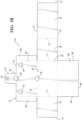
- the wall material can be cut to form the desired size, single, monolithic piece of material that forms the desired configuration of the wall 12, such as shown in Figures 3A and 3B , by way of example and without limitation.
- sides 29 of the planar wall of material are folded appropriately, such as via living side hinges 31, whereupon any free edges needing to be fixed to one another are brought into abutting relation with one another.
- the free edges brought into abutment with one another are readily fixed to one another under, such as via bonding under the application of suitable heat, e.g.
- side edges 27 of the wall 12 can be fixed to one another via one of the aforementioned fixation mechanisms to form a circumferentially continuous, tubular wall structure of the cover 10 bounding the cavity 26.
- the wall 12 is configured having its circumferentially continuous peripheral sides 29 extending between the opposite top and bottom ends 13, 15, wherein at least the top end 13 is open to allow disposal of the battery into the cavity 26.
- the lid 20 could be cut as a single, monolithic piece of material with the peripheral sidewalls 29, as shown in Figures 3A and 3B , or, the lid 20 could be cut as a separate piece of material, and then fixed to one of the upper edges of a sides 29 to form the fixed end 22, such as discussed above, namely, via one of the aforementioned fixation mechanisms, by way of example and without limitation.
- a plurality of through openings 28, 30, 32, 33 are formed in the wall 12, such as in a cutting operation, and are shown as being formed, at least in part, in the lid 20, for example,
- the openings 28, 30, 32 can be formed in the lid 20 prior to fixing the lid 20 to the wall 12,
- One of the openings 28 is adjacent the hinge 25 at the fixed end 22 and another opening 30 is adjacent the opposite free end 24.
- another opening 32 is formed in an extension portion, also referred to as closure flap 34, of the lid 20.
- the flap 34 is shown having a reduced width relative to the full width of the lid 20, by way of example, such that the flap 34 extends outwardly from the free end 24.
- the closure flap 34 is foldable, such as via a living hinge 35, to extend along one of the peripheral sides 29 of the wall 12 to facilitate fastening and maintaining the lid 20 in its closed position.
- the opening 28 adjacent the fixed end 22 of the lid 20 is provided to allow a first elongate fastener member, such as an elongate bolt member or J-hook 36 (known term in the art of vehicle batteries to identify a generally J-shaped fastener, rod or bolt having a J-shaped end configured to loop under the battery or support platform thereof and an opposite, straight threaded end configured for receipt of a threaded nut), to extend therethrough, while the opening 30 adjacent the opposite free end 24 is provided to allow a second elongate fastener member, such as another J-hook 38, to extend therethrough, Accordingly, it should be recognized that the J-hooks 36, 38 run along opposite sides of the cover 10 and battery 11.
- a first elongate fastener member such as an elongate bolt member or J-hook 36 (known term in the art of vehicle batteries to identify a generally J-shaped fastener, rod or bolt having a J-shaped end configured to loop under the battery or support platform thereof and an opposite, straight threaded end configured for
- the openings 33 are provided to accommodate battery terminals 35, such that the terminals 35 are free to pass through the cover 10 in a close fit. It should be recognized that the openings 33 could be provided in a location outer than as shown, depending on the intended use. Meanwhile, as shown in Figure 4 , the opening 32 is provided to facilitate attaching a fastener 40 to the closure flap 34. It should be recognized that the fastener 40 could be fixed to the closure flap 34 without an opening, such as via adhesive bonding, though, this would require additional processes and bonding materials.
- the mechanism shown in Figure 4 is preferred, as the fastener 40 can simply be disposed in snap-fit fashion into the opening 32 along the direction of arrow A, whereupon a pair of spring members or spring fingers 42 function to retain the fastener 40, shown as a spring clip style fastener, in place.
- the fingers 42 upon being compressed radially inwardly and pressed through the opening 32, automatically expand radially outwardly into snap-fit abutment with an inwardly facing side surface 44 of the wall 12 and a flange 46 of the one piece fastener 40 is pressed against an outwardly facing side surface 48 of the wall 12. Accordingly, no extra materials or processes, other than pressing spring fingers 42 of the fastener 40 through the opening 32, are required to fix the fastener 40 to the closure flap 34.
- the battery 11 is placed into the cavity 26 and the J-hooks 36, 38 are placed to extend along opposite sides 29 of the wall 12, Then, the lid 20 is folded about the living hinge 25 over the open top end 13 to cover and conceal the battery 11, whereupon portions of the J-hooks 36, 38 are guided through their respective openings 28, 30 in the lid 20. Further, as shown in Figure 1 , while closing the lid 20, side flaps 49 of the lid 20, if provided for added protection, can be disposed inwardly of opposite sides 29 of the wall 12 to provide added protection to the battery 11.
- the fastener 40 facing inwardly toward the wall 12, is able to be simply and readily fastened via clipped action to the J-hook 38 via spring clip fingers 52, as shown in Figure 4 . Accordingly, assembly of the cover 10, including the lid 20, provides complete coverage about outwardly and upwardly exposed areas of the battery 11, with the bottom of the battery 11 being shielded by shelf 56 upon which the battery 11 rests, with only a single fastener 40 being needed to fix the cover 10 about the battery 11.
- the cover 10 can be formed with an integral bottom 58 formed as a monolithic piece of material with the remaining portion of the cover, as shown in Figure 3B , where the bottom 58 can have side edges 60, with at least one or all of the side edges 60 being fixed, such as being bonded via welded seams, as discussed above, by way of example and without limitation, to abutting bottom ends 15 of the sides 29,
- the remaining installation of the battery 11 with the vehicle can be completed by fastening a standard elongate battery clamp bracket 54 having openings configured for receipt of upper ends of the fastener members 36, 38 therethrough, wherein the bracket 54 generally extends across the width of the battery, whereupon threaded nuts are threaded to the upper end of the J-hooks 36, 38 to press the bracket 54 downwardly, as is known, against the lid 20 of the cover 10, thereby completing the cover-battery assembly.
Landscapes
- Chemical & Material Sciences (AREA)
- Chemical Kinetics & Catalysis (AREA)
- Electrochemistry (AREA)
- General Chemical & Material Sciences (AREA)
- Engineering & Computer Science (AREA)
- Manufacturing & Machinery (AREA)
- Mechanical Engineering (AREA)
- Battery Mounting, Suspending (AREA)
Description
- This invention relates generally to battery covers, and more particularly to flexible, insulative battery covers.
- A thermal insulator is generally needed to insulate a battery, such as a vehicle battery, from thermal degradation. Rigid plastic covers are commonly used to protect batteries; however, they are relatively heavy, and in addition, typically do not protect a battery against thermal conditions. Accordingly, rigid plastic covers generally do not provide the degree of insulation required to protect the battery against thermal degradation, thereby allowing the useful life of the battery to be reduced. In addition, rigid plastic battery covers are inflexible, generally bulky and cumbersome to ship, and in addition, occupy valuable storage space, thereby increasing shipping and inventory cost.
- In addition to rigid plastic covers, generally tubular, nonwoven mats are also used to cover the sides of batteries, wherein the nonwoven mats having open ends, thereby leaving the bottom and top of the battery exposed to environmental conditions. In addition, it is known to cover a top of the battery with a separate piece of material, however, this introduces significant added cost, as a plurality of fasteners are needed to secure the separate piece of material to the nonwoven mat surrounding the sides of the battery. In addition, further cost is added due to the need to inventory separate battery cover components, including the separate pieces of baiter cover materials, as well as the fasteners.
US 4255502 discloses a flexible, fabric cover for automobile batteries.JP S58 110976 U - According to one aspect of the invention, a flexible, insulative battery cover is provided as defined in the appended claims. The cover includes a flexible, tabular textile wall having a cavity extending between a bottom end and an open top end of the wall. The cover further includes a flexible textile lid having a free end and an opposite end attached to the wall via a hinge, with the lid being pivotal via the hinge between an open position, exposing the open top end of the wall, and a closed position, substantially closing off the top end. Further yet, the cover includes a fastener fixed to the lid adjacent the free end, with the fastener being configured for releasable attachment to an elongate fastener member of the vehicle battery assembly.
- The textile wall and lid may include an intermediate nonwoven layer sandwiched between opposite nonwoven scrim layers.
- The nonwoven scrim layers may be spun bond layers.
- The spun bond layers may be constructed at least in part from heat-meltable fibers.
- The lid may have a pair of openings, with one of the openings being adjacent the fixed end of the lid and the other of the openings being adjacent the free end of the lid.
- In accordance with another aspect of the invention, a vehicle battery and insulative cover assembly is provided as defined in the appended claims. The assembly includes a pair of elongate fastener members and an elongate clamp bracket having openings configured for receipt of the fastener members therethrough. The assembly further includes a flexible, tubular textile wall having a cavity extending between a bottom end and an open top find of the wall. A flexible textile lid having a free end and an opposite end is attached to the wall via a hinge. The lid is pivotal via the hinge between an open position, exposing the open top end of the wall, and a closed position, substantially closing off the. Further, a fastener is fixed to the lid adjacent the free end. The fastener is configured for releasable attachment to one of the elongate fastener members, thereby releasably maintaining the lid in the closed position to provide optimal protection to the enclosed battery.
- In accordance with another aspect of the invention, a method of constructing a battery cover for a vehicle batter assembly is provided as defined in the appended claims. The method includes forming a flexible, tubular textile wall to provide a cavity extending between & bottom end and an open top end of the wall. Further, providing a flexible textile lid having a free end and an opposite end attached to the wall via a hinge, with the lid being pivotal via the hinge between an open position, exposing the open top end of the wall, and a closed position, substantially closing off the top end. Further yet, fixing a fastener to the lid adjacent the free end of the lid, with the fastener being configured to for releasable attachment to an elongate fastener member of the vehicle battery assembly.
- In accordance with another aspect of the invention, a method of enclosing a battery in a battery cover is provided as defined in the appended claims. The method includes providing a flexible one piece, insulative battery cover. The cover is provided including a flexible, circumferentially continuous textile wall bounding a cavity that extends between a bottom end of the wall and an open top end of the wall. The cover further includes a flexible textile lid, wherein the lid is hingedly attached to the wall at a fixed end and extends to a free end opposite the fixed end. The cover is further provided with a fastener adjacent the free end. The method further includes disposing a battery in the cavity, and extending fastener members, such as J-hooks, along opposite outer sides of the wall. Then, the method further includes folding the lid from an open position to a closed position, whereupon the fastener members extend through corresponding openings in the lid of the cover. Then, the method includes operably fastening the fastener to one of the fastener members to substantially close the top end of the cover to fully conceal the battery within the cavity. Then, a bracket can be disposed on the fastener members and fastened thereto to fix the enclosed battery to the vehicle.
- These and other aspects, features and advantages of the present invention will become more readily appreciated when considered in connection with the following detailed description of presently preferred embodiments and best mode, appended claims and accompanying drawings, in which:
-
Figure 1 is a perspective view of a one piece, insulative battery cover constructed in accordance with one aspect of the invention shown with a lid of the cover in an open position with a battery disposed in a cavity of the cover; -
Figure 2 is perspective view of the battery cover ofFigure 1 shown disposed within a vehicle in a dosed position with a clamp member fastened to a pair of fastener member J-hooks; -
Figure 3A is a plan view of a flat sheet of material formed into a predetermined configuration, in accordance with one aspect of the invention, with the material shown in an initial fabrication state prior to folding portions of the material into a batter cover; -
Figure 3B is a view similar toFigures 3 A of a flat sheet of material formed into a predetermined configuration, in accordance with another aspect of the invention, with the material shown in an initial fabrication state prior to folding portions of the material into a batter cover; and -
Figure 4 is a cross-sectional view taken generally along the line 4-4 ofFigure 2 showing a fastener of the battery cover fastened to one of the fastener member J-hooks. - Referring in more detail to the drawings,
Figures 1 and2 illustrates a one-piece flexible, textile battery cover, referred to hereafter ascover 10, constructed in accordance with one aspect of the invention shown disposed about a vehicle battery 11 to form an assembly providing thermal protection about the peripheral sides and top of the battery 11, Thecover 10 is formed having a flexible, one-piece wall 12, such that thecover 10 can be handled and disposed about the battery 11 as a single piece of material. Thewall 12 is formed having tubular configured sidewalls, and thus, is circumferentially continuous about its peripheral sides and extends between atop end 13 and an opposite bottom end 15. Thewall 12, as best shown inFigure 4 , has a nonwoven intermediate layer 14 to provide the desired thermal protection, and further includes opposite outer layers 16, 18 sandwiching the intermediate layer 14 therebetween. Thecover 10 further includes a flexible textile top, also referred to aslid 20. Thelid 20 is fixed to thewall 12 adjacent thetop end 13 of thewall 12 at a fixedend 22 of thelid 20, wherein thelid 20 extends to a free end 24 opposite the fixedend 22. Thelid 20 is operable to fold, such as via a living hinge 25 (understood in the art to be an integral hinge formed in the material itself, such as via a creased or reduced thickness region, for example), over theopen top end 13 of thewall 12, thereby closing theopen top end 13 to fully cover the battery 11 within a cavity 26 of thecover 10 and provide complete, enhanced and optimal thermal protection to the battery 11, while at the same time providing fall and completely encapsulated protection to the battery 11 against environmental elements, e.g. fluids and debris contaminants. With the entirety of the fabric forming thecover 10 being highly flexible, thecover 10 is able to be readily compacted or generally flattened for shipping and storage purposes, thereby occupying minimal space in shipping and storage, which ultimately results in reduced shipping and storage costs. Further, the cover is lightweight, thereby minimizing the weight added by thecover 10 to the vehicle. In addition, thecover 10 is readily renewable, and thus, reduces the impact on landfills, and is economical in manufacture and installation. - The intermediate layer 14 can be constructed from green materials, with the green materials being provided from at least one of a blend of comminuted cardboard, natural fibers, recycled materials and/or waste stream materials, and can further include heat-settable fibers and/or heat-meltable textile fibers. The natural fibers can be provided from any suitable natural fibers, such as jute, kenaf, hemp and the like, and also from any suitable recycled materials and/or waste stream materials. The green materials can also be provided as any mixture of Asian (an inferior grade of cardboard commonly produced in Asian countries, e.g. China and Korea and shipped into the U.S., which is typically considered non-recyclable by various state environment agencies heretofore, such as in Connecticut, New Hampshire and Massachusetts) and standard cardboard material (that made from wood, such as pine, which is typical in the U.S.). Because recyclers typically allow only 5% Asian cardboard mixed with the "Standard Cardboard", the focus of this patent is on recycled cardboard with between 5% and 100% Asian cardboard. This "Standard" and "Asian" mixture will hereafter be referred to as "mixed Asian cardboard". As such, a method of recycling cardboard materials for use in manufacturing vehicle components, in accordance with one aspect of the invention, negates the need to separate inferior, low-grade cardboard materials, including Asian cardboard, from higher grade cardboard, such as that manufactured in the U.S. Accordingly, piles, bundles, or mixtures of standard high grade cardboard material from cardboard containers can be readily recycled in combination with the Asian cardboard without concern of separating the two types of cardboard materials from one another. The content of the cardboard, whether mixed or 100% Asian, is preferably between about 25-99 weight percent of the total web weight, depending on the desired characteristics of the
cover 10, as desired. Generally, about 25% recycled material in a new product is needed in order to be considered a "Recycled" product. - If heat-meltable and/or heat-settable material is included in the textile intermediate layer 14, it can be provided, for example, as a low temperature melt polymeric material, such as fibers of polyethylene, PET or Nylon, It should be recognized that other low melt polymeric materials could be used, such as thermoplastic bi-component fibers whose outer sheath, such as polypropylene, for example, melts when heated above its melting point, while the inner core can be a heat-settable material than retains a heat-set shape. The low melt material, when melted, fuses with the mixture of any textile natural fibers present and the cardboard fibers and with remaining binders from the recycled cardboard materials. As an example, the melting point of the outer portion of a PET low melt bi-component fiber may be approximately 110°C - 180°C as compared to the core melting at 250°C. Persons skilled in the art will recognize that other coatings or fillers and filler fibers may be used in place of low melt fibers to achieve the desired result.
- The heat-meltable and thermally bondable textile material is provided having a suitable wt% content of the
wall 12, such as about 10 wt% or more, by way of example and without limitation, to allow any free edges of thewall 12, such as side edges, to be bonded to one another to form the wall having welded seams, and the desired configuration, shown here, by way of example and without limitation, as being generally rectangular. It should be recognized that the wt% of heat-meltable material could be less than 10%, depending on the materials and bonding process used. The heat-meltable fibers are preferably provided from recycled plastic materials, such as recycled carpet or shredded PET rags, for example. Accordingly, the use of these recycled materials reduces the amount of materials being sent to landfills. - The process for constructing the nonwoven textile intermediate layer 14 includes mixing or blending the nonwoven materials, which as discussed, can include green materials, e.g. natural fibers, with the heat-meltable fibers and forming a web of the blended materials. The webbing process, which may be performed in an air-lay process, for example, on a Rando machine, or in a carding process, forms a homogenously mixed natural fiber/meltable fiber mat or web, with the green material and fibers being randomly oriented.
- Then, upon forming the web, the web is consolidated to bind the green and fibrous materials to one another, such as via a mechanical, chemical and/or thermal process. For example, the web can be heated, such as in an oven, to a temperature suitable to at least partially melt the heat-meltable fibers, thereby thermally bonding the blend of green materials with the heat-meltable fibers. Otherwise, or in addition, the web can be subjected to a needling process to entwine the green materials and fibers with one another and/or to a chemical process wherein a chemical binder is utilized to bond the green materials and fibers together. Regardless of the consolidating process selected, the web is formed into a nonwoven sheet of intermixed and intertwined fibers, wherein the nonwoven sheet attains a desired thickness.
- Then, upon forming and cooling the nonwoven sheet 14, the outer layers 16, 18 can be bonded to the opposite sides of the intermediate layer 14 to complete the formation of the material of the
wall 12. The outer layers 16, 18 can be formed of any suitable material desired to provide protection to the battery 11 against environmental elements, including engine fluids and water. As such, the outer layers 16, 18 can be provided as fluid impervious or substantially impervious layers of material, such as from scrim layers of nonwoven material, wherein the outer layers 16, 18 can be formed as relatively thin spun bond layers, as compared to the thicker intermediate layer 14. By way of example and without limitation, the outer layers 16, 18 can be formed, at least in part, from polypropylene. Then, upon completing construction of the wall material, the wall material can be cut to form the desired size, single, monolithic piece of material that forms the desired configuration of thewall 12, such as shown inFigures 3A and3B , by way of example and without limitation. Then, sides 29 of the planar wall of material are folded appropriately, such as via living side hinges 31, whereupon any free edges needing to be fixed to one another are brought into abutting relation with one another. The free edges brought into abutment with one another are readily fixed to one another under, such as via bonding under the application of suitable heat, e.g. welded, such as in an ultrasonic welding process, or by a suitable adhesive or fastener, for example, By way of example and without limitation, side edges 27 of thewall 12 can be fixed to one another via one of the aforementioned fixation mechanisms to form a circumferentially continuous, tubular wall structure of thecover 10 bounding the cavity 26. As such, thewall 12 is configured having its circumferentially continuous peripheral sides 29 extending between the opposite top and bottom ends 13, 15, wherein at least thetop end 13 is open to allow disposal of the battery into the cavity 26. It is contemplated herein that thelid 20 could be cut as a single, monolithic piece of material with the peripheral sidewalls 29, as shown inFigures 3A and3B , or, thelid 20 could be cut as a separate piece of material, and then fixed to one of the upper edges of a sides 29 to form thefixed end 22, such as discussed above, namely, via one of the aforementioned fixation mechanisms, by way of example and without limitation. - Upon forming the overall planar geometry of the
wall 12, including thelid 20, a plurality of throughopenings wall 12, such as in a cutting operation, and are shown as being formed, at least in part, in thelid 20, for example, Of course, if thelid 20 is constructed separately from thewall 12, theopenings 28, 30, 32 can be formed in thelid 20 prior to fixing thelid 20 to thewall 12, One of the openings 28 is adjacent the hinge 25 at thefixed end 22 and another opening 30 is adjacent the opposite free end 24. Further yet, anotheropening 32 is formed in an extension portion, also referred to asclosure flap 34, of thelid 20. Theflap 34 is shown having a reduced width relative to the full width of thelid 20, by way of example, such that theflap 34 extends outwardly from the free end 24. Upon closing thelid 20, theclosure flap 34 is foldable, such as via aliving hinge 35, to extend along one of the peripheral sides 29 of thewall 12 to facilitate fastening and maintaining thelid 20 in its closed position. The opening 28 adjacent thefixed end 22 of thelid 20 is provided to allow a first elongate fastener member, such as an elongate bolt member or J-hook 36 (known term in the art of vehicle batteries to identify a generally J-shaped fastener, rod or bolt having a J-shaped end configured to loop under the battery or support platform thereof and an opposite, straight threaded end configured for receipt of a threaded nut), to extend therethrough, while the opening 30 adjacent the opposite free end 24 is provided to allow a second elongate fastener member, such as another J-hook 38, to extend therethrough, Accordingly, it should be recognized that the J-hooks 36, 38 run along opposite sides of thecover 10 and battery 11. Theopenings 33 are provided to accommodatebattery terminals 35, such that theterminals 35 are free to pass through thecover 10 in a close fit. It should be recognized that theopenings 33 could be provided in a location outer than as shown, depending on the intended use. Meanwhile, as shown inFigure 4 , theopening 32 is provided to facilitate attaching a fastener 40 to theclosure flap 34. It should be recognized that the fastener 40 could be fixed to theclosure flap 34 without an opening, such as via adhesive bonding, though, this would require additional processes and bonding materials. Accordingly, the mechanism shown inFigure 4 is preferred, as the fastener 40 can simply be disposed in snap-fit fashion into theopening 32 along the direction of arrow A, whereupon a pair of spring members or spring fingers 42 function to retain the fastener 40, shown as a spring clip style fastener, in place. The fingers 42, upon being compressed radially inwardly and pressed through theopening 32, automatically expand radially outwardly into snap-fit abutment with an inwardly facing side surface 44 of thewall 12 and a flange 46 of the one piece fastener 40 is pressed against an outwardly facing side surface 48 of thewall 12. Accordingly, no extra materials or processes, other than pressing spring fingers 42 of the fastener 40 through theopening 32, are required to fix the fastener 40 to theclosure flap 34. - Upon completing construction of the
cover 10, the battery 11 is placed into the cavity 26 and the J-hooks 36, 38 are placed to extend along opposite sides 29 of thewall 12, Then, thelid 20 is folded about the living hinge 25 over the opentop end 13 to cover and conceal the battery 11, whereupon portions of the J-hooks 36, 38 are guided through their respective openings 28, 30 in thelid 20. Further, as shown inFigure 1 , while closing thelid 20, side flaps 49 of thelid 20, if provided for added protection, can be disposed inwardly of opposite sides 29 of thewall 12 to provide added protection to the battery 11. Then, the fastener 40, facing inwardly toward thewall 12, is able to be simply and readily fastened via clipped action to the J-hook 38 via spring clip fingers 52, as shown inFigure 4 . Accordingly, assembly of thecover 10, including thelid 20, provides complete coverage about outwardly and upwardly exposed areas of the battery 11, with the bottom of the battery 11 being shielded byshelf 56 upon which the battery 11 rests, with only a single fastener 40 being needed to fix thecover 10 about the battery 11. Of course, thecover 10 can be formed with an integral bottom 58 formed as a monolithic piece of material with the remaining portion of the cover, as shown inFigure 3B , where the bottom 58 can have side edges 60, with at least one or all of the side edges 60 being fixed, such as being bonded via welded seams, as discussed above, by way of example and without limitation, to abutting bottom ends 15 of the sides 29, With the battery 11 being fully enclosed in thecover 10, the remaining installation of the battery 11 with the vehicle can be completed by fastening a standard elongate battery clamp bracket 54 having openings configured for receipt of upper ends of thefastener members 36, 38 therethrough, wherein the bracket 54 generally extends across the width of the battery, whereupon threaded nuts are threaded to the upper end of the J-hooks 36, 38 to press the bracket 54 downwardly, as is known, against thelid 20 of thecover 10, thereby completing the cover-battery assembly. - Obviously, many modifications and variations of the present invention are possible in light of the above teachings, It is, therefore, to be understood that within the scope of the appended claims and any claims ultimately allowed, the invention may be practiced otherwise than as specifically described.
Claims (13)
- A vehicle battery and insulative cover assembly, comprising;a flexible, tubular textile wall (12) having a cavity (26) extending between a bottom end (15) and an open top end (13) of said wall (12);a flexible textile lid (20) having a free end (24) and an opposite end (22) attached to said wall via a hinge (25), said lid (20) being pivotal via said hinge (25) between an open position, exposing said open top end (13) of said wall (12), and a closed position, substantially closing off said top end (13);characterized bya pair of elongate fastener members (36, 38); an elongate clamp bracket (54) having openings configured for receipt of said fastener members therethrough; anda fastener (40) fixed to said lid (20) adjacent said free end (24), said fastener (40) being configured for releasable attachment to one of said elongate fastener members (36, 38).
- The assembly of claim 1 wherein said wall (12) and said lid (20) are a monolithic piece material with said hinge (25) being a living hinge (25).
- The assembly of claim 2 wherein said wall (12) and said lid (20) having a nonwoven intermediate layer sandwiched between substantially impervious outer layers.
- The assembly of claim 1 wherein said wall (12) has a plurality of through openings (28, 30), a first of said openings (28, 30) being adjacent said hinge (25) and a second of said openings (28, 30) being adjacent said free end (24), wherein said first and second openings (28, 30) are configured for receipt of separate ones of said elongate fastener members (36, 38) therethrough.
- The assembly of claim 1 wherein said lid (20) has a flap (34) foldable to extend along a side of said tubular wall (12) via a living hinge (35), said fastener (40) being fixed to said flap (34).
- The assembly of claim 1 wherein said fastener (40) has spring clip fingers (52) for snapping attachment to said one of said elongate fastener members (36, 38).
- The assembly of claim 1 wherein said lid (20) has a pair of side flaps (50) configured for receipt in said cavity (26) inside said wall (12).
- A flexible, insulative battery cover (10) for use in a vehicle battery and insulative cover assembly according to claim 1, the cover (10) comprising:a flexible, tubular textile wall (12) having a cavity (26) extending between a bottom end (15) and an open top end (13) of said wall (12);a flexible textile lid (20) having a free end (24) and an opposite end (22) attached to said wall via a hinge (25), said lid (20) being pivotal via said hinge (25) between an open position, exposing said open top end (13) of said wall (12), and a closed position, substantially closing off said top end (13);characterized bya fastener (40) fixed to said lid (20) adjacent said free end (24),wherein said wall (12) has a plurality of through openings (28, 30) including a first opening (28) adjacent said hinge (25) and a second opening (30) adjacent said free end (24), said first and second openings being configured for receipt therethrough of a separate elongate fastener member of the vehicle battery and insulative cover assembly, said fastener (40) being configured for releasable attachment to the elongate fastener member (38) that is received by the second opening (30).
- The flexible, insulative battery cover (10) of claim 8, wherein said wall (12) and said lid (20) are a monolithic piece material, with said hinge (25) being a living hinge.
- This flexible, insulative battery cover (10) of claim 9, wherein said wall (12) and said lid (20) having a nonwoven intermediate layer (14) sandwiched between substantially fluid impervious outer layers (16, 18).
- The flexible, insulative battery cover (10) of claim 8, wherein said lid (20) has a flap (34) foldable to extend along a side of said tubular wall (12) via a living hinge (25), said fastener (40) being fixed to said flap.
- The flexible, insulative battery cover (10) of claim 8, wherein said fastener (40) has spring clip fingers (52) for snapping attachment to the elongate fastener member (38).
- The flexible, insulative battery cover (10) of claim 8, wherein said lid (20) has a pair of side flaps (49) configured for receipt in said cavity (26) inside said wall (12).
Applications Claiming Priority (2)
| Application Number | Priority Date | Filing Date | Title |
|---|---|---|---|
| US201462043969P | 2014-08-29 | 2014-08-29 | |
| PCT/US2015/046511 WO2016032945A1 (en) | 2014-08-29 | 2015-08-24 | Flexible battery cover with integral lid, method of construction thereof, and method of enclosing a battery therewith |
Publications (2)
| Publication Number | Publication Date |
|---|---|
| EP3194216A1 EP3194216A1 (en) | 2017-07-26 |
| EP3194216B1 true EP3194216B1 (en) | 2024-04-17 |
Family
ID=54066202
Family Applications (1)
| Application Number | Title | Priority Date | Filing Date |
|---|---|---|---|
| EP15760556.9A Active EP3194216B1 (en) | 2014-08-29 | 2015-08-24 | Flexible battery cover with integral lid, method of construction thereof, and method of enclosing a battery therewith |
Country Status (2)
| Country | Link |
|---|---|
| EP (1) | EP3194216B1 (en) |
| CN (1) | CN106797059B (en) |
Families Citing this family (1)
| Publication number | Priority date | Publication date | Assignee | Title |
|---|---|---|---|---|
| CN116037727B (en) * | 2022-11-30 | 2025-11-11 | 苏州上良自动化设备有限公司 | Grinding and heat setting mechanism for soft flanging folding of terminal board |
Citations (9)
| Publication number | Priority date | Publication date | Assignee | Title |
|---|---|---|---|---|
| JPS58110976U (en) * | 1982-01-22 | 1983-07-28 | 若林 雄治 | Cold protection cover for battery |
| US4535863A (en) * | 1983-08-26 | 1985-08-20 | Becker John R | Battery security and hold-down device |
| US4738906A (en) * | 1985-04-30 | 1988-04-19 | Weather Ready Inc. | Storage battery heating and heat maintenance apparatus |
| GB2213981A (en) * | 1987-12-22 | 1989-08-23 | Philip Raymon Lee | Vehicle battery protection device |
| US6010804A (en) * | 1998-04-30 | 2000-01-04 | Barksdale; Henry R. | Protective cover and connection device for batteries |
| US20030047364A1 (en) * | 2000-12-12 | 2003-03-13 | Murray Lipman | Pre-wired battery box for rapid installaionand connection of batteries |
| US7301303B1 (en) * | 2004-08-16 | 2007-11-27 | International Specialty Services, Inc. | Portable battery jump start in a soft-sided carrying case |
| US20100147918A1 (en) * | 2008-12-12 | 2010-06-17 | Hensley Patrick L | Bag |
| EP2323193A2 (en) * | 2009-11-12 | 2011-05-18 | GARDENA Manufacturing GmbH | Portable battery assembly and container for battery |
Family Cites Families (6)
| Publication number | Priority date | Publication date | Assignee | Title |
|---|---|---|---|---|
| US4255502A (en) * | 1979-09-07 | 1981-03-10 | Michael D. Taylor | Cover for automobile batteries |
| JP4848733B2 (en) * | 2004-10-22 | 2011-12-28 | 日産自動車株式会社 | Battery module and battery pack |
| US8795872B2 (en) * | 2010-07-26 | 2014-08-05 | Enerdel, Inc. | Battery cell system with interconnected frames |
| CN202399877U (en) * | 2011-12-31 | 2012-08-29 | 河南速达电动汽车科技有限公司 | Back-arranged energy storing device of electric automobile |
| CN203225283U (en) * | 2013-03-29 | 2013-10-02 | 上海泰瑞电子科技有限公司 | Storage battery protecting jacket for automobile |
| CN103633490B (en) * | 2013-11-28 | 2015-09-30 | 四川航天计量测试研究所 | The reliable plug-in connection of a kind of connector without latch assembly and assembly method thereof and docking calculation |
-
2015
- 2015-08-24 EP EP15760556.9A patent/EP3194216B1/en active Active
- 2015-08-24 CN CN201580054022.9A patent/CN106797059B/en active Active
Patent Citations (9)
| Publication number | Priority date | Publication date | Assignee | Title |
|---|---|---|---|---|
| JPS58110976U (en) * | 1982-01-22 | 1983-07-28 | 若林 雄治 | Cold protection cover for battery |
| US4535863A (en) * | 1983-08-26 | 1985-08-20 | Becker John R | Battery security and hold-down device |
| US4738906A (en) * | 1985-04-30 | 1988-04-19 | Weather Ready Inc. | Storage battery heating and heat maintenance apparatus |
| GB2213981A (en) * | 1987-12-22 | 1989-08-23 | Philip Raymon Lee | Vehicle battery protection device |
| US6010804A (en) * | 1998-04-30 | 2000-01-04 | Barksdale; Henry R. | Protective cover and connection device for batteries |
| US20030047364A1 (en) * | 2000-12-12 | 2003-03-13 | Murray Lipman | Pre-wired battery box for rapid installaionand connection of batteries |
| US7301303B1 (en) * | 2004-08-16 | 2007-11-27 | International Specialty Services, Inc. | Portable battery jump start in a soft-sided carrying case |
| US20100147918A1 (en) * | 2008-12-12 | 2010-06-17 | Hensley Patrick L | Bag |
| EP2323193A2 (en) * | 2009-11-12 | 2011-05-18 | GARDENA Manufacturing GmbH | Portable battery assembly and container for battery |
Also Published As
| Publication number | Publication date |
|---|---|
| CN106797059A (en) | 2017-05-31 |
| EP3194216A1 (en) | 2017-07-26 |
| CN106797059B (en) | 2020-02-25 |
Similar Documents
| Publication | Publication Date | Title |
|---|---|---|
| US10249855B2 (en) | Flexible battery cover with integral lid, method of construction thereof, and method of enclosing a battery therewith | |
| EP2122054B1 (en) | Nonwoven panel and method of construction thereof | |
| US11081751B2 (en) | Battery cover and method of construction thereof | |
| CA2393765A1 (en) | Acoustical fibrous insulation product for use in a vehicle | |
| US20110070794A1 (en) | Nonwoven sheet material, panel constructed therefrom and methods of construction thereof | |
| EP3423269B1 (en) | Multi-layer acoustic and/or reinforcing non-woven fabric | |
| US10367177B2 (en) | Flexible green nonwoven battery cover and method of construction thereof | |
| EP3194216A1 (en) | Flexible battery cover with integral lid, method of construction thereof, and method of enclosing a battery therewith | |
| EP2534290B1 (en) | Method of construction of a high loft nonwoven sheet material | |
| US20110189911A1 (en) | High loft nonwoven sheet material and method of construction thereof | |
| JP2000276179A (en) | Soundproofing material and method for manufacturing the soundproofing material | |
| KR200159666Y1 (en) | Renewable Insulation Curtain for Green House | |
| CN115087381A (en) | Holding plate for a vacuum cleaner filter bag | |
| WO2015130909A1 (en) | Nonwoven panel formed of end-of-life ingredients and method of construction thereof | |
| TH16831B (en) | Filters and manufacturing processes for this purpose. |
Legal Events
| Date | Code | Title | Description |
|---|---|---|---|
| STAA | Information on the status of an ep patent application or granted ep patent |
Free format text: STATUS: THE INTERNATIONAL PUBLICATION HAS BEEN MADE |
|
| PUAI | Public reference made under article 153(3) epc to a published international application that has entered the european phase |
Free format text: ORIGINAL CODE: 0009012 |
|
| STAA | Information on the status of an ep patent application or granted ep patent |
Free format text: STATUS: REQUEST FOR EXAMINATION WAS MADE |
|
| 17P | Request for examination filed |
Effective date: 20170217 |
|
| AK | Designated contracting states |
Kind code of ref document: A1 Designated state(s): AL AT BE BG CH CY CZ DE DK EE ES FI FR GB GR HR HU IE IS IT LI LT LU LV MC MK MT NL NO PL PT RO RS SE SI SK SM TR |
|
| AX | Request for extension of the european patent |
Extension state: BA ME |
|
| DAV | Request for validation of the european patent (deleted) | ||
| DAX | Request for extension of the european patent (deleted) | ||
| RAP1 | Party data changed (applicant data changed or rights of an application transferred) |
Owner name: FEDERAL-MOGUL POWERTRAIN LLC |
|
| STAA | Information on the status of an ep patent application or granted ep patent |
Free format text: STATUS: EXAMINATION IS IN PROGRESS |
|
| 17Q | First examination report despatched |
Effective date: 20181008 |
|
| P01 | Opt-out of the competence of the unified patent court (upc) registered |
Effective date: 20230528 |
|
| REG | Reference to a national code |
Ref country code: DE Ref legal event code: R079 Free format text: PREVIOUS MAIN CLASS: B60R0016040000 Ipc: H01M0050240000 Ref document number: 602015088352 Country of ref document: DE |
|
| GRAP | Despatch of communication of intention to grant a patent |
Free format text: ORIGINAL CODE: EPIDOSNIGR1 |
|
| STAA | Information on the status of an ep patent application or granted ep patent |
Free format text: STATUS: GRANT OF PATENT IS INTENDED |
|
| RIC1 | Information provided on ipc code assigned before grant |
Ipc: H01M 10/613 20140101ALI20231124BHEP Ipc: H01M 10/658 20140101ALI20231124BHEP Ipc: H01M 10/647 20140101ALI20231124BHEP Ipc: H01M 10/625 20140101ALI20231124BHEP Ipc: H01M 50/282 20210101ALI20231124BHEP Ipc: H01M 50/262 20210101ALI20231124BHEP Ipc: H01M 50/24 20210101AFI20231124BHEP |
|
| INTG | Intention to grant announced |
Effective date: 20231219 |
|
| GRAS | Grant fee paid |
Free format text: ORIGINAL CODE: EPIDOSNIGR3 |
|
| GRAA | (expected) grant |
Free format text: ORIGINAL CODE: 0009210 |
|
| STAA | Information on the status of an ep patent application or granted ep patent |
Free format text: STATUS: THE PATENT HAS BEEN GRANTED |
|
| AK | Designated contracting states |
Kind code of ref document: B1 Designated state(s): AL AT BE BG CH CY CZ DE DK EE ES FI FR GB GR HR HU IE IS IT LI LT LU LV MC MK MT NL NO PL PT RO RS SE SI SK SM TR |
|
| REG | Reference to a national code |
Ref country code: GB Ref legal event code: FG4D |
|
| REG | Reference to a national code |
Ref country code: CH Ref legal event code: EP |
|
| REG | Reference to a national code |
Ref country code: DE Ref legal event code: R096 Ref document number: 602015088352 Country of ref document: DE |
|
| REG | Reference to a national code |
Ref country code: IE Ref legal event code: FG4D |
|
| REG | Reference to a national code |
Ref country code: LT Ref legal event code: MG9D |
|
| REG | Reference to a national code |
Ref country code: NL Ref legal event code: MP Effective date: 20240417 |
|
| REG | Reference to a national code |
Ref country code: AT Ref legal event code: MK05 Ref document number: 1678166 Country of ref document: AT Kind code of ref document: T Effective date: 20240417 |
|
| PG25 | Lapsed in a contracting state [announced via postgrant information from national office to epo] |
Ref country code: NL Free format text: LAPSE BECAUSE OF FAILURE TO SUBMIT A TRANSLATION OF THE DESCRIPTION OR TO PAY THE FEE WITHIN THE PRESCRIBED TIME-LIMIT Effective date: 20240417 |
|
| PG25 | Lapsed in a contracting state [announced via postgrant information from national office to epo] |
Ref country code: NL Free format text: LAPSE BECAUSE OF FAILURE TO SUBMIT A TRANSLATION OF THE DESCRIPTION OR TO PAY THE FEE WITHIN THE PRESCRIBED TIME-LIMIT Effective date: 20240417 |
|
| PG25 | Lapsed in a contracting state [announced via postgrant information from national office to epo] |
Ref country code: IS Free format text: LAPSE BECAUSE OF FAILURE TO SUBMIT A TRANSLATION OF THE DESCRIPTION OR TO PAY THE FEE WITHIN THE PRESCRIBED TIME-LIMIT Effective date: 20240817 |
|
| PG25 | Lapsed in a contracting state [announced via postgrant information from national office to epo] |
Ref country code: BG Free format text: LAPSE BECAUSE OF FAILURE TO SUBMIT A TRANSLATION OF THE DESCRIPTION OR TO PAY THE FEE WITHIN THE PRESCRIBED TIME-LIMIT Effective date: 20240417 |
|
| PG25 | Lapsed in a contracting state [announced via postgrant information from national office to epo] |
Ref country code: HR Free format text: LAPSE BECAUSE OF FAILURE TO SUBMIT A TRANSLATION OF THE DESCRIPTION OR TO PAY THE FEE WITHIN THE PRESCRIBED TIME-LIMIT Effective date: 20240417 Ref country code: FI Free format text: LAPSE BECAUSE OF FAILURE TO SUBMIT A TRANSLATION OF THE DESCRIPTION OR TO PAY THE FEE WITHIN THE PRESCRIBED TIME-LIMIT Effective date: 20240417 |
|
| PG25 | Lapsed in a contracting state [announced via postgrant information from national office to epo] |
Ref country code: GR Free format text: LAPSE BECAUSE OF FAILURE TO SUBMIT A TRANSLATION OF THE DESCRIPTION OR TO PAY THE FEE WITHIN THE PRESCRIBED TIME-LIMIT Effective date: 20240718 |
|
| PG25 | Lapsed in a contracting state [announced via postgrant information from national office to epo] |
Ref country code: PT Free format text: LAPSE BECAUSE OF FAILURE TO SUBMIT A TRANSLATION OF THE DESCRIPTION OR TO PAY THE FEE WITHIN THE PRESCRIBED TIME-LIMIT Effective date: 20240819 |
|
| PG25 | Lapsed in a contracting state [announced via postgrant information from national office to epo] |
Ref country code: ES Free format text: LAPSE BECAUSE OF FAILURE TO SUBMIT A TRANSLATION OF THE DESCRIPTION OR TO PAY THE FEE WITHIN THE PRESCRIBED TIME-LIMIT Effective date: 20240417 |
|
| PG25 | Lapsed in a contracting state [announced via postgrant information from national office to epo] |
Ref country code: AT Free format text: LAPSE BECAUSE OF FAILURE TO SUBMIT A TRANSLATION OF THE DESCRIPTION OR TO PAY THE FEE WITHIN THE PRESCRIBED TIME-LIMIT Effective date: 20240417 |
|
| PG25 | Lapsed in a contracting state [announced via postgrant information from national office to epo] |
Ref country code: PL Free format text: LAPSE BECAUSE OF FAILURE TO SUBMIT A TRANSLATION OF THE DESCRIPTION OR TO PAY THE FEE WITHIN THE PRESCRIBED TIME-LIMIT Effective date: 20240417 |
|
| PG25 | Lapsed in a contracting state [announced via postgrant information from national office to epo] |
Ref country code: LV Free format text: LAPSE BECAUSE OF FAILURE TO SUBMIT A TRANSLATION OF THE DESCRIPTION OR TO PAY THE FEE WITHIN THE PRESCRIBED TIME-LIMIT Effective date: 20240417 |
|
| PG25 | Lapsed in a contracting state [announced via postgrant information from national office to epo] |
Ref country code: PT Free format text: LAPSE BECAUSE OF FAILURE TO SUBMIT A TRANSLATION OF THE DESCRIPTION OR TO PAY THE FEE WITHIN THE PRESCRIBED TIME-LIMIT Effective date: 20240819 Ref country code: PL Free format text: LAPSE BECAUSE OF FAILURE TO SUBMIT A TRANSLATION OF THE DESCRIPTION OR TO PAY THE FEE WITHIN THE PRESCRIBED TIME-LIMIT Effective date: 20240417 Ref country code: NO Free format text: LAPSE BECAUSE OF FAILURE TO SUBMIT A TRANSLATION OF THE DESCRIPTION OR TO PAY THE FEE WITHIN THE PRESCRIBED TIME-LIMIT Effective date: 20240717 Ref country code: LV Free format text: LAPSE BECAUSE OF FAILURE TO SUBMIT A TRANSLATION OF THE DESCRIPTION OR TO PAY THE FEE WITHIN THE PRESCRIBED TIME-LIMIT Effective date: 20240417 Ref country code: IS Free format text: LAPSE BECAUSE OF FAILURE TO SUBMIT A TRANSLATION OF THE DESCRIPTION OR TO PAY THE FEE WITHIN THE PRESCRIBED TIME-LIMIT Effective date: 20240817 Ref country code: HR Free format text: LAPSE BECAUSE OF FAILURE TO SUBMIT A TRANSLATION OF THE DESCRIPTION OR TO PAY THE FEE WITHIN THE PRESCRIBED TIME-LIMIT Effective date: 20240417 Ref country code: GR Free format text: LAPSE BECAUSE OF FAILURE TO SUBMIT A TRANSLATION OF THE DESCRIPTION OR TO PAY THE FEE WITHIN THE PRESCRIBED TIME-LIMIT Effective date: 20240718 Ref country code: FI Free format text: LAPSE BECAUSE OF FAILURE TO SUBMIT A TRANSLATION OF THE DESCRIPTION OR TO PAY THE FEE WITHIN THE PRESCRIBED TIME-LIMIT Effective date: 20240417 Ref country code: ES Free format text: LAPSE BECAUSE OF FAILURE TO SUBMIT A TRANSLATION OF THE DESCRIPTION OR TO PAY THE FEE WITHIN THE PRESCRIBED TIME-LIMIT Effective date: 20240417 Ref country code: BG Free format text: LAPSE BECAUSE OF FAILURE TO SUBMIT A TRANSLATION OF THE DESCRIPTION OR TO PAY THE FEE WITHIN THE PRESCRIBED TIME-LIMIT Effective date: 20240417 Ref country code: AT Free format text: LAPSE BECAUSE OF FAILURE TO SUBMIT A TRANSLATION OF THE DESCRIPTION OR TO PAY THE FEE WITHIN THE PRESCRIBED TIME-LIMIT Effective date: 20240417 Ref country code: RS Free format text: LAPSE BECAUSE OF FAILURE TO SUBMIT A TRANSLATION OF THE DESCRIPTION OR TO PAY THE FEE WITHIN THE PRESCRIBED TIME-LIMIT Effective date: 20240717 |
|
| PG25 | Lapsed in a contracting state [announced via postgrant information from national office to epo] |
Ref country code: DK Free format text: LAPSE BECAUSE OF FAILURE TO SUBMIT A TRANSLATION OF THE DESCRIPTION OR TO PAY THE FEE WITHIN THE PRESCRIBED TIME-LIMIT Effective date: 20240417 |
|
| REG | Reference to a national code |
Ref country code: DE Ref legal event code: R097 Ref document number: 602015088352 Country of ref document: DE |
|
| PG25 | Lapsed in a contracting state [announced via postgrant information from national office to epo] |
Ref country code: EE Free format text: LAPSE BECAUSE OF FAILURE TO SUBMIT A TRANSLATION OF THE DESCRIPTION OR TO PAY THE FEE WITHIN THE PRESCRIBED TIME-LIMIT Effective date: 20240417 |
|
| PG25 | Lapsed in a contracting state [announced via postgrant information from national office to epo] |
Ref country code: CZ Free format text: LAPSE BECAUSE OF FAILURE TO SUBMIT A TRANSLATION OF THE DESCRIPTION OR TO PAY THE FEE WITHIN THE PRESCRIBED TIME-LIMIT Effective date: 20240417 |
|
| PG25 | Lapsed in a contracting state [announced via postgrant information from national office to epo] |
Ref country code: SK Free format text: LAPSE BECAUSE OF FAILURE TO SUBMIT A TRANSLATION OF THE DESCRIPTION OR TO PAY THE FEE WITHIN THE PRESCRIBED TIME-LIMIT Effective date: 20240417 Ref country code: RO Free format text: LAPSE BECAUSE OF FAILURE TO SUBMIT A TRANSLATION OF THE DESCRIPTION OR TO PAY THE FEE WITHIN THE PRESCRIBED TIME-LIMIT Effective date: 20240417 |
|
| PG25 | Lapsed in a contracting state [announced via postgrant information from national office to epo] |
Ref country code: SM Free format text: LAPSE BECAUSE OF FAILURE TO SUBMIT A TRANSLATION OF THE DESCRIPTION OR TO PAY THE FEE WITHIN THE PRESCRIBED TIME-LIMIT Effective date: 20240417 |
|
| PG25 | Lapsed in a contracting state [announced via postgrant information from national office to epo] |
Ref country code: SM Free format text: LAPSE BECAUSE OF FAILURE TO SUBMIT A TRANSLATION OF THE DESCRIPTION OR TO PAY THE FEE WITHIN THE PRESCRIBED TIME-LIMIT Effective date: 20240417 Ref country code: SK Free format text: LAPSE BECAUSE OF FAILURE TO SUBMIT A TRANSLATION OF THE DESCRIPTION OR TO PAY THE FEE WITHIN THE PRESCRIBED TIME-LIMIT Effective date: 20240417 Ref country code: RO Free format text: LAPSE BECAUSE OF FAILURE TO SUBMIT A TRANSLATION OF THE DESCRIPTION OR TO PAY THE FEE WITHIN THE PRESCRIBED TIME-LIMIT Effective date: 20240417 Ref country code: EE Free format text: LAPSE BECAUSE OF FAILURE TO SUBMIT A TRANSLATION OF THE DESCRIPTION OR TO PAY THE FEE WITHIN THE PRESCRIBED TIME-LIMIT Effective date: 20240417 Ref country code: DK Free format text: LAPSE BECAUSE OF FAILURE TO SUBMIT A TRANSLATION OF THE DESCRIPTION OR TO PAY THE FEE WITHIN THE PRESCRIBED TIME-LIMIT Effective date: 20240417 Ref country code: CZ Free format text: LAPSE BECAUSE OF FAILURE TO SUBMIT A TRANSLATION OF THE DESCRIPTION OR TO PAY THE FEE WITHIN THE PRESCRIBED TIME-LIMIT Effective date: 20240417 |
|
| PG25 | Lapsed in a contracting state [announced via postgrant information from national office to epo] |
Ref country code: IT Free format text: LAPSE BECAUSE OF FAILURE TO SUBMIT A TRANSLATION OF THE DESCRIPTION OR TO PAY THE FEE WITHIN THE PRESCRIBED TIME-LIMIT Effective date: 20240417 |
|
| PLBE | No opposition filed within time limit |
Free format text: ORIGINAL CODE: 0009261 |
|
| STAA | Information on the status of an ep patent application or granted ep patent |
Free format text: STATUS: NO OPPOSITION FILED WITHIN TIME LIMIT |
|
| REG | Reference to a national code |
Ref country code: DE Ref legal event code: R119 Ref document number: 602015088352 Country of ref document: DE |
|
| 26N | No opposition filed |
Effective date: 20250120 |
|
| REG | Reference to a national code |
Ref country code: CH Ref legal event code: PL |
|
| PG25 | Lapsed in a contracting state [announced via postgrant information from national office to epo] |
Ref country code: LU Free format text: LAPSE BECAUSE OF NON-PAYMENT OF DUE FEES Effective date: 20240824 |
|
| GBPC | Gb: european patent ceased through non-payment of renewal fee |
Effective date: 20240824 |
|
| PG25 | Lapsed in a contracting state [announced via postgrant information from national office to epo] |
Ref country code: SI Free format text: LAPSE BECAUSE OF FAILURE TO SUBMIT A TRANSLATION OF THE DESCRIPTION OR TO PAY THE FEE WITHIN THE PRESCRIBED TIME-LIMIT Effective date: 20240417 Ref country code: MC Free format text: LAPSE BECAUSE OF FAILURE TO SUBMIT A TRANSLATION OF THE DESCRIPTION OR TO PAY THE FEE WITHIN THE PRESCRIBED TIME-LIMIT Effective date: 20240417 Ref country code: CH Free format text: LAPSE BECAUSE OF NON-PAYMENT OF DUE FEES Effective date: 20240831 |
|
| REG | Reference to a national code |
Ref country code: BE Ref legal event code: MM Effective date: 20240831 |
|
| PG25 | Lapsed in a contracting state [announced via postgrant information from national office to epo] |
Ref country code: DE Free format text: LAPSE BECAUSE OF NON-PAYMENT OF DUE FEES Effective date: 20250301 |
|
| PG25 | Lapsed in a contracting state [announced via postgrant information from national office to epo] |
Ref country code: GB Free format text: LAPSE BECAUSE OF NON-PAYMENT OF DUE FEES Effective date: 20240824 |
|
| PG25 | Lapsed in a contracting state [announced via postgrant information from national office to epo] |
Ref country code: BE Free format text: LAPSE BECAUSE OF NON-PAYMENT OF DUE FEES Effective date: 20240831 |
|
| PG25 | Lapsed in a contracting state [announced via postgrant information from national office to epo] |
Ref country code: FR Free format text: LAPSE BECAUSE OF NON-PAYMENT OF DUE FEES Effective date: 20240831 |
|
| PG25 | Lapsed in a contracting state [announced via postgrant information from national office to epo] |
Ref country code: IE Free format text: LAPSE BECAUSE OF NON-PAYMENT OF DUE FEES Effective date: 20240824 |
|
| PG25 | Lapsed in a contracting state [announced via postgrant information from national office to epo] |
Ref country code: SE Free format text: LAPSE BECAUSE OF FAILURE TO SUBMIT A TRANSLATION OF THE DESCRIPTION OR TO PAY THE FEE WITHIN THE PRESCRIBED TIME-LIMIT Effective date: 20240417 |
|
| PG25 | Lapsed in a contracting state [announced via postgrant information from national office to epo] |
Ref country code: CY Free format text: LAPSE BECAUSE OF FAILURE TO SUBMIT A TRANSLATION OF THE DESCRIPTION OR TO PAY THE FEE WITHIN THE PRESCRIBED TIME-LIMIT; INVALID AB INITIO Effective date: 20150824 |
|
| PG25 | Lapsed in a contracting state [announced via postgrant information from national office to epo] |
Ref country code: HU Free format text: LAPSE BECAUSE OF FAILURE TO SUBMIT A TRANSLATION OF THE DESCRIPTION OR TO PAY THE FEE WITHIN THE PRESCRIBED TIME-LIMIT; INVALID AB INITIO Effective date: 20150824 |