EP3194062B1 - Apparatus for dispensing a liquid - Google Patents
Apparatus for dispensing a liquid Download PDFInfo
- Publication number
- EP3194062B1 EP3194062B1 EP15763373.6A EP15763373A EP3194062B1 EP 3194062 B1 EP3194062 B1 EP 3194062B1 EP 15763373 A EP15763373 A EP 15763373A EP 3194062 B1 EP3194062 B1 EP 3194062B1
- Authority
- EP
- European Patent Office
- Prior art keywords
- pump
- valve
- liquid
- dispense
- opening
- Prior art date
- Legal status (The legal status is an assumption and is not a legal conclusion. Google has not performed a legal analysis and makes no representation as to the accuracy of the status listed.)
- Active
Links
Images

Classifications
-
- B—PERFORMING OPERATIONS; TRANSPORTING
- B05—SPRAYING OR ATOMISING IN GENERAL; APPLYING FLUENT MATERIALS TO SURFACES, IN GENERAL
- B05B—SPRAYING APPARATUS; ATOMISING APPARATUS; NOZZLES
- B05B15/00—Details of spraying plant or spraying apparatus not otherwise provided for; Accessories
- B05B15/50—Arrangements for cleaning; Arrangements for preventing deposits, drying-out or blockage; Arrangements for detecting improper discharge caused by the presence of foreign matter
- B05B15/52—Arrangements for cleaning; Arrangements for preventing deposits, drying-out or blockage; Arrangements for detecting improper discharge caused by the presence of foreign matter for removal of clogging particles
- B05B15/531—Arrangements for cleaning; Arrangements for preventing deposits, drying-out or blockage; Arrangements for detecting improper discharge caused by the presence of foreign matter for removal of clogging particles using backflow
-
- F—MECHANICAL ENGINEERING; LIGHTING; HEATING; WEAPONS; BLASTING
- F04—POSITIVE - DISPLACEMENT MACHINES FOR LIQUIDS; PUMPS FOR LIQUIDS OR ELASTIC FLUIDS
- F04B—POSITIVE-DISPLACEMENT MACHINES FOR LIQUIDS; PUMPS
- F04B13/00—Pumps specially modified to deliver fixed or variable measured quantities
-
- B—PERFORMING OPERATIONS; TRANSPORTING
- B01—PHYSICAL OR CHEMICAL PROCESSES OR APPARATUS IN GENERAL
- B01F—MIXING, e.g. DISSOLVING, EMULSIFYING OR DISPERSING
- B01F25/00—Flow mixers; Mixers for falling materials, e.g. solid particles
- B01F25/50—Circulation mixers, e.g. wherein at least part of the mixture is discharged from and reintroduced into a receptacle
-
- B—PERFORMING OPERATIONS; TRANSPORTING
- B01—PHYSICAL OR CHEMICAL PROCESSES OR APPARATUS IN GENERAL
- B01F—MIXING, e.g. DISSOLVING, EMULSIFYING OR DISPERSING
- B01F33/00—Other mixers; Mixing plants; Combinations of mixers
- B01F33/80—Mixing plants; Combinations of mixers
- B01F33/84—Mixing plants with mixing receptacles receiving material dispensed from several component receptacles, e.g. paint tins
- B01F33/841—Mixing plants with mixing receptacles receiving material dispensed from several component receptacles, e.g. paint tins with component receptacles fixed in a circular configuration on a horizontal table, e.g. the table being able to be indexed about a vertical axis
-
- B—PERFORMING OPERATIONS; TRANSPORTING
- B01—PHYSICAL OR CHEMICAL PROCESSES OR APPARATUS IN GENERAL
- B01F—MIXING, e.g. DISSOLVING, EMULSIFYING OR DISPERSING
- B01F35/00—Accessories for mixers; Auxiliary operations or auxiliary devices; Parts or details of general application
- B01F35/10—Maintenance of mixers
- B01F35/12—Maintenance of mixers using mechanical means
- B01F35/122—Maintenance of mixers using mechanical means using pushers, i.e. a piston, for pushing out rests of products
-
- B—PERFORMING OPERATIONS; TRANSPORTING
- B01—PHYSICAL OR CHEMICAL PROCESSES OR APPARATUS IN GENERAL
- B01F—MIXING, e.g. DISSOLVING, EMULSIFYING OR DISPERSING
- B01F35/00—Accessories for mixers; Auxiliary operations or auxiliary devices; Parts or details of general application
- B01F35/20—Measuring; Control or regulation
- B01F35/21—Measuring
- B01F35/2136—Viscosity
-
- B—PERFORMING OPERATIONS; TRANSPORTING
- B01—PHYSICAL OR CHEMICAL PROCESSES OR APPARATUS IN GENERAL
- B01F—MIXING, e.g. DISSOLVING, EMULSIFYING OR DISPERSING
- B01F35/00—Accessories for mixers; Auxiliary operations or auxiliary devices; Parts or details of general application
- B01F35/75—Discharge mechanisms
- B01F35/754—Discharge mechanisms characterised by the means for discharging the components from the mixer
- B01F35/7544—Discharge mechanisms characterised by the means for discharging the components from the mixer using pumps
-
- B—PERFORMING OPERATIONS; TRANSPORTING
- B01—PHYSICAL OR CHEMICAL PROCESSES OR APPARATUS IN GENERAL
- B01F—MIXING, e.g. DISSOLVING, EMULSIFYING OR DISPERSING
- B01F35/00—Accessories for mixers; Auxiliary operations or auxiliary devices; Parts or details of general application
- B01F35/75—Discharge mechanisms
- B01F35/754—Discharge mechanisms characterised by the means for discharging the components from the mixer
- B01F35/7547—Discharge mechanisms characterised by the means for discharging the components from the mixer using valves, gates, orifices or openings
-
- B—PERFORMING OPERATIONS; TRANSPORTING
- B01—PHYSICAL OR CHEMICAL PROCESSES OR APPARATUS IN GENERAL
- B01F—MIXING, e.g. DISSOLVING, EMULSIFYING OR DISPERSING
- B01F35/00—Accessories for mixers; Auxiliary operations or auxiliary devices; Parts or details of general application
- B01F35/80—Forming a predetermined ratio of the substances to be mixed
- B01F35/88—Forming a predetermined ratio of the substances to be mixed by feeding the materials batchwise
- B01F35/882—Forming a predetermined ratio of the substances to be mixed by feeding the materials batchwise using measuring chambers, e.g. volumetric pumps, for feeding the substances
- B01F35/8822—Forming a predetermined ratio of the substances to be mixed by feeding the materials batchwise using measuring chambers, e.g. volumetric pumps, for feeding the substances using measuring chambers of the piston or plunger type
-
- F—MECHANICAL ENGINEERING; LIGHTING; HEATING; WEAPONS; BLASTING
- F04—POSITIVE - DISPLACEMENT MACHINES FOR LIQUIDS; PUMPS FOR LIQUIDS OR ELASTIC FLUIDS
- F04B—POSITIVE-DISPLACEMENT MACHINES FOR LIQUIDS; PUMPS
- F04B15/00—Pumps adapted to handle specific fluids, e.g. by selection of specific materials for pumps or pump parts
- F04B15/02—Pumps adapted to handle specific fluids, e.g. by selection of specific materials for pumps or pump parts the fluids being viscous or non-homogeneous
-
- F—MECHANICAL ENGINEERING; LIGHTING; HEATING; WEAPONS; BLASTING
- F04—POSITIVE - DISPLACEMENT MACHINES FOR LIQUIDS; PUMPS FOR LIQUIDS OR ELASTIC FLUIDS
- F04B—POSITIVE-DISPLACEMENT MACHINES FOR LIQUIDS; PUMPS
- F04B23/00—Pumping installations or systems
- F04B23/02—Pumping installations or systems having reservoirs
-
- F—MECHANICAL ENGINEERING; LIGHTING; HEATING; WEAPONS; BLASTING
- F04—POSITIVE - DISPLACEMENT MACHINES FOR LIQUIDS; PUMPS FOR LIQUIDS OR ELASTIC FLUIDS
- F04B—POSITIVE-DISPLACEMENT MACHINES FOR LIQUIDS; PUMPS
- F04B23/00—Pumping installations or systems
- F04B23/04—Combinations of two or more pumps
- F04B23/06—Combinations of two or more pumps the pumps being all of reciprocating positive-displacement type
-
- F—MECHANICAL ENGINEERING; LIGHTING; HEATING; WEAPONS; BLASTING
- F04—POSITIVE - DISPLACEMENT MACHINES FOR LIQUIDS; PUMPS FOR LIQUIDS OR ELASTIC FLUIDS
- F04B—POSITIVE-DISPLACEMENT MACHINES FOR LIQUIDS; PUMPS
- F04B7/00—Piston machines or pumps characterised by having positively-driven valving
- F04B7/0003—Piston machines or pumps characterised by having positively-driven valving the distribution member forming both the inlet and discharge distributor for one single pumping chamber
- F04B7/0007—Piston machines or pumps characterised by having positively-driven valving the distribution member forming both the inlet and discharge distributor for one single pumping chamber and having a rotating movement
-
- F—MECHANICAL ENGINEERING; LIGHTING; HEATING; WEAPONS; BLASTING
- F04—POSITIVE - DISPLACEMENT MACHINES FOR LIQUIDS; PUMPS FOR LIQUIDS OR ELASTIC FLUIDS
- F04B—POSITIVE-DISPLACEMENT MACHINES FOR LIQUIDS; PUMPS
- F04B7/00—Piston machines or pumps characterised by having positively-driven valving
- F04B7/0042—Piston machines or pumps characterised by having positively-driven valving with specific kinematics of the distribution member
- F04B7/0046—Piston machines or pumps characterised by having positively-driven valving with specific kinematics of the distribution member for rotating distribution members
-
- F—MECHANICAL ENGINEERING; LIGHTING; HEATING; WEAPONS; BLASTING
- F16—ENGINEERING ELEMENTS AND UNITS; GENERAL MEASURES FOR PRODUCING AND MAINTAINING EFFECTIVE FUNCTIONING OF MACHINES OR INSTALLATIONS; THERMAL INSULATION IN GENERAL
- F16K—VALVES; TAPS; COCKS; ACTUATING-FLOATS; DEVICES FOR VENTING OR AERATING
- F16K11/00—Multiple-way valves, e.g. mixing valves; Pipe fittings incorporating such valves
- F16K11/02—Multiple-way valves, e.g. mixing valves; Pipe fittings incorporating such valves with all movable sealing faces moving as one unit
- F16K11/08—Multiple-way valves, e.g. mixing valves; Pipe fittings incorporating such valves with all movable sealing faces moving as one unit comprising only taps or cocks
- F16K11/087—Multiple-way valves, e.g. mixing valves; Pipe fittings incorporating such valves with all movable sealing faces moving as one unit comprising only taps or cocks with spherical plug
- F16K11/0873—Multiple-way valves, e.g. mixing valves; Pipe fittings incorporating such valves with all movable sealing faces moving as one unit comprising only taps or cocks with spherical plug the plug being only rotatable around one spindle
- F16K11/0876—Multiple-way valves, e.g. mixing valves; Pipe fittings incorporating such valves with all movable sealing faces moving as one unit comprising only taps or cocks with spherical plug the plug being only rotatable around one spindle one connecting conduit having the same axis as the spindle
-
- B—PERFORMING OPERATIONS; TRANSPORTING
- B01—PHYSICAL OR CHEMICAL PROCESSES OR APPARATUS IN GENERAL
- B01F—MIXING, e.g. DISSOLVING, EMULSIFYING OR DISPERSING
- B01F2101/00—Mixing characterised by the nature of the mixed materials or by the application field
- B01F2101/30—Mixing paints or paint ingredients, e.g. pigments, dyes, colours, lacquers or enamel
Definitions
- the invention relates to an apparatus for dispensing colorants for paint.
- US 2003/183654 A1 relates to a valve assembly for a fluid dispenser, which includes a housing having at least a first opening and a second opening, a valve member fitted in the housing, the valve member being rotatable about an axis and comprising a first channel, extending along said axis and communicating with the first opening in the housing, and at least two outlet channels radially extending from the first channel to the circumference of the valve member, wherein each of the radially extending outlet channels can be brought in register with the second opening by rotating the valve member.
- US 2012/250451 relates to a method of homogenizing a liquid, in particular a colorant for paint, in a container, comprising the steps of withdrawing liquid from the container at a first flow speed (SI) and then returning the liquid to the container at a second flow speed (S2), higher than the first flow speed (SI).
- SI first flow speed
- S2 second flow speed
- purging i.e. dispensing a small amount of colorant to clean the dispense opening and thus reduce the risk of so-called mistints resulting from nozzle blockage e.g. caused by colorant drying in the dispense opening
- purging implies waste of colorant.
- the invention relates to an apparatus according to claim 1.
- each one of the assemblies comprises at least one further dispense opening, e.g., having a diameter different from the diameter of the first dispense opening, e.g. smaller to allow more accurate dispensing or larger to allow faster dispensing, and wherein the controller is arranged to operate the pump and the valve to purge liquid from the pump to the container via the at least one further dispense opening, preferably via all dispense openings in succession.
- the valve in a first position, connects the container to the pump and, in a second or further position, connects the pump to the at least one dispense opening.
- the valve comprises a rotatable valve member, e.g. a valve ball, cylinder or disc, and the dispense opening or openings is respectively are defined in the valve member, e.g. as a channel or channels that extends respectively extend radially or axially in the valve member.
- the liquid is dispensed directly from the valve member, e.g. through a larger opening in the valve, e.g. in the housing of the valve, preferably preventing the liquid from contacting the larger opening.
- the dispense opening can be cleaned by the purging with colorant itself and yet, because the purged colorant is returned to the container, waste is reduced or prevented altogether.
- the openings are all located within 120°, preferably within 110°, of rotation of the valve member from each other. Thus, total rotation required to purge all openings is limited and operation facilitated.
- the controller can be, e.g., positioned at a dispense position and coupled with the other parts when these are at the dispense position.
- the controller in a position of the valve, at least the pump is closed and the controller is arranged to establish, preferably by measuring the compressibility or expandability of the medium e.g. by measuring resistance in or stroke of the pump, whether and, if so, to what extent the medium contains air.
- the controller in a position of the valve, all suction and dispense openings and routes are closed.
- the liquid inside the pump allows more compression or expansion than the liquid as such, this is an indication that the liquid contains air.
- the liquid may contain air as a result of e.g. production or mixing of the liquid or of an empty container, refilling of a container, or a leaking seal in the assembly.
- the degree of displacement provides an indication of the root cause.
- Pump condition and/or container filling status can be registered and communicated to the operator and/or service representative e.g. by means of signals and/or a log.
- the valve comprises a variable opening and/or a plurality of different openings and the controller is arranged to establish whether flow resistance in the liquid over the opening. This can be achieved e.g. by accurately controlling the valve and/or shaping the openings, e.g. oval, diamond or oblong, to vary overlap between internal openings and/or providing two or more channels having different diameters and/or different effective cross-sections and thus set flow resistance.
- This provides a means for determining the condition of the liquid, e.g. by measuring flow resistance from the control of motor driving the pump, e.g., at different openings or overlaps. Overlap and/or shape and/or surface and/or length (in flow direction) of the opening will affect the shear in the liquid and, e.g., for shear thinning and/or shear thickening liquids this will provide information whether a certain viscosity yield value is still present, which can serve as an indication of the condition of the liquid.
- Measurements of (parameters indicative of) compressibility, expandability or flow resistance can be performed automatically, e.g. periodically and/or outside business hours, and a signal generated to inform an operator or service representative.
- the controller is arranged to purge the dispense opening (s) and perform said measurements automatically, e.g. periodically and/or outside business hours.
- the pump is a positive displacement pump, preferably a reciprocating pump, preferably a piston pump.
- the apparatus of the invention can be used for dispensing a liquid, in particular a colorant for paint, from the assemblies, comprising the steps of withdrawing liquid from the container and dispense the liquid from the dispense opening, and characterised by purging liquid from the pump to the container via the dispense opening.
- the assembly comprises a further dispense opening, wherein liquid is purged from the pump to the container via the further dispense opening.
- the pump is closed by means of the valve and the degree of compressibility or expandability of the liquid in the pump is established.
- use of the apparatus comprises varying an opening, e.g. between the pump and the container, generating a flow of the liquid through different openings and establishing flow resistance in the liquid over the different openings.
- liquid is defined as any flowable material that comprises a liquid phase and thus includes suspensions and emulsions.
- Colorants often contain a high density of pigments or particles suspended in (instable) liquid binder/solvent solutions.
- FIG. 1 illustrates the main parts of an example of an apparatus 1 for dispensing colorants or dyes.
- This particular dispensing apparatus includes a turntable 2 rotatable about a vertical axis by means of a drive (not shown) in order to rotate the turntable 2 between discrete positions.
- On the turntable 2 there are mounted a plurality of assemblies 3, each comprising a container 4 for holding a liquid, pump 5, and a valve 6. Further details of the said apparatus and turntable are disclosed in U.S. Pat. No. 6,273, 298 .
- FIGS 2 to 4 show cross-sections of the pump 5 and valve 6.
- the pump 5 is a piston pump and includes a piston rod 5A provided with a piston 5B, disposed within a cylinder 5C of the pump 5, and an upper flange 5D.
- the flange 5D can be engaged by a controller 7 comprising an actuator (not shown) adapted to move the piston rod 5A and the piston 5B upwards during an intake stroke and downwards during a dispense stroke and an actuator (not shown) to operate the valve 6.
- the controller 7 and actuators are stationary and arranged to position one of the assemblies 3 in line with the actuators in order to enable actuating the pump 5 and the valve 6.
- the cylinder 5C is mounted in the top part of a pump housing 9, which defines a cavity 10 and further includes an inlet channel 11 that is separated from the cavity 10 and adapted to be in fluid communication with a container 4 as shown in Figure 1 .
- the valve member 15 is provided with a lever 17 with which it can be rotated about an axis A by means of the corresponding actuator.
- the valve housing 12 further defines a cavity 18 limited at its upper part by a first opening 19, through which the cavity 18 communicates with the cavity 10 of the pump housing 9.
- the valve housing 12 further includes a second opening 20 in its bottom part and a third opening 21 which communicates with the inlet channel 11 in the pump housing 9.
- the valve member 15 includes a first channel 22, extending along the axis A and communicating with the first opening 19 in the housing 12. It further includes at least two dispense openings, in this example in the form of outlet channels 23, 24, and an inlet channel 25, all radially extending from the first channel 22 to the circumference of the valve member 15.
- the diameter of one of the outlet channels 23 is smaller than that of the other 24 and the diameter of both outlet channels 23, 24 is smaller than that of the inlet channel 25.
- both of these diameters are smaller than the diameter of the outlet opening 20 in the housing 12 and the central axes of channels 23-25 are all located on the same sectional plane through the valve member 15 and are respectively, e.g., 30 °C and 100 °C apart.
- Figures 2 to 4 show the intake position of the valve member, where the inlet channel 25 of the valve member 15 is in registry with the third opening 21 of the valve housing 12 and thus with the inlet channel 11.
- the container communicates with the cavity 10 in the pump housing 9 and the cylinder 7.
- the cavity 10 and cylinder 7 now can be filled with a desired amount of the liquid from the container by moving the piston 6 upwards over a desired or predetermined length.
- the inlet channel 22 temporarily serves as an outlet channel.
- valve member 15 can be rotated to the desired dispensing position, i.e., until the desired dispense channel 23, 24 is in register with the opening 20 in the housing and the piston 6 can be moved downwards to dispense a desired or predetermined amount from the said opening 20. If this amount of liquid is relatively small and/or the dosage should be precise, the relatively narrow output channel 23 is appropriate and, if this amount is relatively large and/or should be dispensed rapidly, the relatively wide output channel 24 is appropriate.
- the valve assembly enables the tailored and, if need be, precise and/or rapid dispensing of viscous liquids, without having to exchange the valve assembly or components of the valve assembly.
- valve member 15 is rotated until the desired dispense channel - the larger diameter channel in Figure 5A and the smaller diameter channel in Figure 5B - to be purged is in register with the third opening 22 in the housing 12, which communicates with container 4. In these positions, the piston 6 is moved downwards to purge a predetermined amount of liquid through the dispense channel back to the container 4.
- Figure 6 shows a further embodiment of a valve according to the present invention in seven positions.
- the radial dispense channels 23, 24 are 108° apart and the intake channel 25 is positioned in between the dispense channels.
- the positions are, in succession, intake or return of liquid via the intake channel 25, purging the larger diameter dispense channel 24 by returning liquid to the container, purging the smaller diameter dispense channel 23 by returning liquid to the container, closing the pump from all suction and dispense openings and routes fluid, dispensing via the smaller diameter dispense channel 23, dispensing via the larger diameter dispense channel 24, and dispensing via the intake channel 25.
Landscapes
- Engineering & Computer Science (AREA)
- Chemical & Material Sciences (AREA)
- Chemical Kinetics & Catalysis (AREA)
- Mechanical Engineering (AREA)
- General Engineering & Computer Science (AREA)
- Loading And Unloading Of Fuel Tanks Or Ships (AREA)
- Containers And Packaging Bodies Having A Special Means To Remove Contents (AREA)
- Details Of Reciprocating Pumps (AREA)
- Devices For Dispensing Beverages (AREA)
Description
- The invention relates to an apparatus for dispensing colorants for paint.
-
US 2,985,339 discloses an example of such an apparatus. -
US 2003/183654 A1 relates to a valve assembly for a fluid dispenser, which includes a housing having at least a first opening and a second opening, a valve member fitted in the housing, the valve member being rotatable about an axis and comprising a first channel, extending along said axis and communicating with the first opening in the housing, and at least two outlet channels radially extending from the first channel to the circumference of the valve member, wherein each of the radially extending outlet channels can be brought in register with the second opening by rotating the valve member. -
US 2012/250451 relates to a method of homogenizing a liquid, in particular a colorant for paint, in a container, comprising the steps of withdrawing liquid from the container at a first flow speed (SI) and then returning the liquid to the container at a second flow speed (S2), higher than the first flow speed (SI). - In colorant dispensers for paint, purging, i.e. dispensing a small amount of colorant to clean the dispense opening and thus reduce the risk of so-called mistints resulting from nozzle blockage e.g. caused by colorant drying in the dispense opening, is a common and effective practice, as for example is disclosed in
CN 103968106 A . However, purging implies waste of colorant. - It is an object of the present invention to provide effective cleaning of the dispense opening and yet reduce or prevent such waste.
- The invention relates to an apparatus according to claim 1.
- In an embodiment, each one of the assemblies comprises at least one further dispense opening, e.g., having a diameter different from the diameter of the first dispense opening, e.g. smaller to allow more accurate dispensing or larger to allow faster dispensing, and wherein the controller is arranged to operate the pump and the valve to purge liquid from the pump to the container via the at least one further dispense opening, preferably via all dispense openings in succession. In another embodiment, the valve, in a first position, connects the container to the pump and, in a second or further position, connects the pump to the at least one dispense opening.
- In a further embodiment, the valve comprises a rotatable valve member, e.g. a valve ball, cylinder or disc, and the dispense opening or openings is respectively are defined in the valve member, e.g. as a channel or channels that extends respectively extend radially or axially in the valve member. Thus, the liquid is dispensed directly from the valve member, e.g. through a larger opening in the valve, e.g. in the housing of the valve, preferably preventing the liquid from contacting the larger opening.
- With the present invention the dispense opening can be cleaned by the purging with colorant itself and yet, because the purged colorant is returned to the container, waste is reduced or prevented altogether.
- In a refinement, the openings are all located within 120°, preferably within 110°, of rotation of the valve member from each other. Thus, total rotation required to purge all openings is limited and operation facilitated.
- The controller can be, e.g., positioned at a dispense position and coupled with the other parts when these are at the dispense position.
- According to the invention, in a position of the valve, at least the pump is closed and the controller is arranged to establish, preferably by measuring the compressibility or expandability of the medium e.g. by measuring resistance in or stroke of the pump, whether and, if so, to what extent the medium contains air. In a refinement, in a position of the valve, all suction and dispense openings and routes are closed.
- If the liquid inside the pump allows more compression or expansion than the liquid as such, this is an indication that the liquid contains air. The liquid may contain air as a result of e.g. production or mixing of the liquid or of an empty container, refilling of a container, or a leaking seal in the assembly. The degree of displacement provides an indication of the root cause. Pump condition and/or container filling status can be registered and communicated to the operator and/or service representative e.g. by means of signals and/or a log.
- In a further embodiment, the valve comprises a variable opening and/or a plurality of different openings and the controller is arranged to establish whether flow resistance in the liquid over the opening. This can be achieved e.g. by accurately controlling the valve and/or shaping the openings, e.g. oval, diamond or oblong, to vary overlap between internal openings and/or providing two or more channels having different diameters and/or different effective cross-sections and thus set flow resistance.
- This provides a means for determining the condition of the liquid, e.g. by measuring flow resistance from the control of motor driving the pump, e.g., at different openings or overlaps. Overlap and/or shape and/or surface and/or length (in flow direction) of the opening will affect the shear in the liquid and, e.g., for shear thinning and/or shear thickening liquids this will provide information whether a certain viscosity yield value is still present, which can serve as an indication of the condition of the liquid.
- Measurements of (parameters indicative of) compressibility, expandability or flow resistance can be performed automatically, e.g. periodically and/or outside business hours, and a signal generated to inform an operator or service representative.
- In another embodiment, the controller is arranged to purge the dispense opening (s) and perform said measurements automatically, e.g. periodically and/or outside business hours.
- In a further embodiment, the pump is a positive displacement pump, preferably a reciprocating pump, preferably a piston pump.
- The apparatus of the invention can be used for dispensing a liquid, in particular a colorant for paint, from the assemblies, comprising the steps of withdrawing liquid from the container and dispense the liquid from the dispense opening, and characterised by purging liquid from the pump to the container via the dispense opening. In an embodiment, the assembly comprises a further dispense opening, wherein liquid is purged from the pump to the container via the further dispense opening.
- In another embodiment, the pump is closed by means of the valve and the degree of compressibility or expandability of the liquid in the pump is established.
- Optionally, use of the apparatus comprises varying an opening, e.g. between the pump and the container, generating a flow of the liquid through different openings and establishing flow resistance in the liquid over the different openings.
- Within the framework of the present invention the term "liquid" is defined as any flowable material that comprises a liquid phase and thus includes suspensions and emulsions. Colorants often contain a high density of pigments or particles suspended in (instable) liquid binder/solvent solutions.
- The disclosed invention will be further explained with reference to the accompanying drawings in which presently preferred embodiments of the invention are shown schematically.
-
Figure 1 is a perspective view of a part of a disclosed apparatus for dispensing liquid colorants. -
Figure 2 is cross-sectional side view of a disclosed valve assembly suitable for use in the apparatus ofFigure 1 . -
Figure 3 is a partial detailed view of the valve assembly ofFigure 2 . -
Figure 4 is a cross-sectional front view of the valve assembly as shown inFigure 3 . -
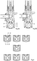
Figures 5A and 5B show the same detail asFigure 3 at different positions of the valve. -
Figure 6 shows part of a further embodiment comprising a different valve at seven positions. -
Figure 1 illustrates the main parts of an example of an apparatus 1 for dispensing colorants or dyes. This particular dispensing apparatus includes aturntable 2 rotatable about a vertical axis by means of a drive (not shown) in order to rotate theturntable 2 between discrete positions. On theturntable 2, there are mounted a plurality of assemblies 3, each comprising acontainer 4 for holding a liquid,pump 5, and a valve 6. Further details of the said apparatus and turntable are disclosed inU.S. Pat. No. 6,273, 298 . -
Figures 2 to 4 show cross-sections of thepump 5 and valve 6. Thepump 5 is a piston pump and includes apiston rod 5A provided with apiston 5B, disposed within acylinder 5C of thepump 5, and anupper flange 5D. Theflange 5D can be engaged by a controller 7 comprising an actuator (not shown) adapted to move thepiston rod 5A and thepiston 5B upwards during an intake stroke and downwards during a dispense stroke and an actuator (not shown) to operate the valve 6. - The controller 7 and actuators are stationary and arranged to position one of the assemblies 3 in line with the actuators in order to enable actuating the
pump 5 and the valve 6. Thecylinder 5C is mounted in the top part of apump housing 9, which defines acavity 10 and further includes aninlet channel 11 that is separated from thecavity 10 and adapted to be in fluid communication with acontainer 4 as shown inFigure 1 . - A
valve housing 12, comprising acover 12A, is attached to the lower part of thepump housing 9 by means ofrespective flanges ball 15, is fitted in thehousing 12 by means of twoannular bearings valve member 15 is provided with alever 17 with which it can be rotated about an axis A by means of the corresponding actuator. Thevalve housing 12 further defines acavity 18 limited at its upper part by afirst opening 19, through which thecavity 18 communicates with thecavity 10 of thepump housing 9. Thevalve housing 12 further includes a second opening 20 in its bottom part and a third opening 21 which communicates with theinlet channel 11 in thepump housing 9. Thevalve member 15 includes afirst channel 22, extending along the axis A and communicating with thefirst opening 19 in thehousing 12. It further includes at least two dispense openings, in this example in the form ofoutlet channels inlet channel 25, all radially extending from thefirst channel 22 to the circumference of thevalve member 15. In this particular embodiment, the diameter of one of theoutlet channels 23 is smaller than that of the other 24 and the diameter of bothoutlet channels inlet channel 25. Further, both of these diameters are smaller than the diameter of the outlet opening 20 in thehousing 12 and the central axes of channels 23-25 are all located on the same sectional plane through thevalve member 15 and are respectively, e.g., 30 °C and 100 °C apart. -
Figures 2 to 4 show the intake position of the valve member, where theinlet channel 25 of thevalve member 15 is in registry with the third opening 21 of thevalve housing 12 and thus with theinlet channel 11. In other words, the container communicates with thecavity 10 in thepump housing 9 and the cylinder 7. In this position, thecavity 10 and cylinder 7 now can be filled with a desired amount of the liquid from the container by moving the piston 6 upwards over a desired or predetermined length. It is noted that, in this position, theinlet channel 22 temporarily serves as an outlet channel. - As soon as an appropriate amount of liquid is taken in, the
valve member 15 can be rotated to the desired dispensing position, i.e., until the desired dispensechannel opening 20 in the housing and the piston 6 can be moved downwards to dispense a desired or predetermined amount from the saidopening 20. If this amount of liquid is relatively small and/or the dosage should be precise, the relativelynarrow output channel 23 is appropriate and, if this amount is relatively large and/or should be dispensed rapidly, the relativelywide output channel 24 is appropriate. Thus, the valve assembly enables the tailored and, if need be, precise and/or rapid dispensing of viscous liquids, without having to exchange the valve assembly or components of the valve assembly. - During purging, shown in
Figures 5A and 5B , thevalve member 15 is rotated until the desired dispense channel - the larger diameter channel inFigure 5A and the smaller diameter channel inFigure 5B - to be purged is in register with thethird opening 22 in thehousing 12, which communicates withcontainer 4. In these positions, the piston 6 is moved downwards to purge a predetermined amount of liquid through the dispense channel back to thecontainer 4. -
Figure 6 shows a further embodiment of a valve according to the present invention in seven positions. In this embodiment, the radial dispensechannels intake channel 25 is positioned in between the dispense channels. The positions are, in succession, intake or return of liquid via theintake channel 25, purging the larger diameter dispensechannel 24 by returning liquid to the container, purging the smaller diameter dispensechannel 23 by returning liquid to the container, closing the pump from all suction and dispense openings and routes fluid, dispensing via the smaller diameter dispensechannel 23, dispensing via the larger diameter dispensechannel 24, and dispensing via theintake channel 25. - As a matter of course, the invention is not restricted to the above-disclosed embodiment and can be varied in numerous ways within the scope of the claims.
Claims (8)
- Apparatus (1) for dispensing colorants for paint, comprising a plurality of assemblies (3), each assembly comprising a container (4) for holding a liquid, a pump (5), a valve (6), at least one dispense opening (23, 24), and comprising a controller (7) arranged to operate the pump (5) and the valve (6) to withdraw liquid from the container (4) and to dispense liquid via the dispense opening (23, 24) and to operate the pump (5) and the valve (6) to purge liquid from the pump (5) to the container (4) via the dispense opening (23, 24), characterized in that the valve (6), in a further position, closes at least the pump (5), wherein the controller (7) is arranged to establish whether the liquid inside the pump (5) is compressible or expandable.
- Apparatus (1) according to claim 1, each assembly comprising at least one further dispense opening (24), e.g. having a diameter different from the diameter of the first dispense opening (23), and wherein the controller (7) is arranged to operate the pump (5) and the valve (6) to purge liquid from the pump (5) to the container (4) via the at least one further dispense opening (24), preferably via all dispense openings (23, 24).
- Apparatus (1) according to claim 1 or 2, wherein the valve (6), in a first position, connects the container (4) to the pump (5) and, in a second or further position, connects the pump (5) to the at least one dispense opening (23, 24).
- Apparatus (1) according to any one of the preceding claims, wherein the valve (6) comprises a rotatable valve member (15) and the dispense opening (23) or openings (23, 24) is/are defined in the valve member (15).
- Apparatus (1) according to claim 4, wherein the openings (23, 24) are all located within 120°, preferably within 110°, of rotation of the valve member (15) from each other.
- Apparatus (1) according to any one of the preceding claims, wherein the valve (6) comprises a plurality of different openings (23, 24) and/or a variable opening and wherein the controller (7) is arranged to establish whether flow resistance in the liquid over the opening(s) (23, 24).
- Apparatus (1) according to any one of the preceding claims, wherein the controller (7) is arranged to purge the dispense opening(s) (23, 24) and/or establish compressibility, expandability and/or flow resistance automatically.
- Apparatus (3) according to any one of the preceding claims, wherein the pump is a positive displacement pump, preferably a reciprocating pump, preferably a piston pump (5).
Applications Claiming Priority (2)
| Application Number | Priority Date | Filing Date | Title |
|---|---|---|---|
| EP14185202.0A EP2998016A1 (en) | 2014-09-17 | 2014-09-17 | Assembly for and method of dispensing a liquid |
| PCT/EP2015/071375 WO2016042104A1 (en) | 2014-09-17 | 2015-09-17 | Assembly for and method of dispensing a liquid |
Publications (3)
| Publication Number | Publication Date |
|---|---|
| EP3194062A1 EP3194062A1 (en) | 2017-07-26 |
| EP3194062B1 true EP3194062B1 (en) | 2025-03-12 |
| EP3194062C0 EP3194062C0 (en) | 2025-03-12 |
Family
ID=51589113
Family Applications (2)
| Application Number | Title | Priority Date | Filing Date |
|---|---|---|---|
| EP14185202.0A Withdrawn EP2998016A1 (en) | 2014-09-17 | 2014-09-17 | Assembly for and method of dispensing a liquid |
| EP15763373.6A Active EP3194062B1 (en) | 2014-09-17 | 2015-09-17 | Apparatus for dispensing a liquid |
Family Applications Before (1)
| Application Number | Title | Priority Date | Filing Date |
|---|---|---|---|
| EP14185202.0A Withdrawn EP2998016A1 (en) | 2014-09-17 | 2014-09-17 | Assembly for and method of dispensing a liquid |
Country Status (4)
| Country | Link |
|---|---|
| US (2) | US12070765B2 (en) |
| EP (2) | EP2998016A1 (en) |
| CN (2) | CN119455771A (en) |
| WO (1) | WO2016042104A1 (en) |
Families Citing this family (15)
| Publication number | Priority date | Publication date | Assignee | Title |
|---|---|---|---|---|
| EP3318318A1 (en) * | 2016-11-04 | 2018-05-09 | Fast&Fluid Management B.V. | Dispensing apparatus and releasably connectable fluid container for use in such dispensing apparatus |
| EP3395454B1 (en) * | 2017-04-26 | 2022-11-02 | Fast & Fluid Management B.V. | Dispenser for tinting pastes |
| CN108325401A (en) * | 2018-01-17 | 2018-07-27 | 天津博迈科海洋工程有限公司 | It is a kind of can be with the air and liquid mixer of quick-replaceable caliber |
| JP2019184494A (en) * | 2018-04-13 | 2019-10-24 | 東芝テック株式会社 | Droplet dispensing device |
| CN113766968A (en) * | 2019-02-12 | 2021-12-07 | 克洛布股份公司 | Machine and method for automatic dispensing of fluid products, especially liquid dyes |
| EP3712432B1 (en) | 2019-03-19 | 2024-07-17 | Fast & Fluid Management B.V. | Liquid dispenser and method of operating such a dispenser |
| MX2021015263A (en) * | 2019-06-11 | 2022-04-06 | Corob Spa | ASSEMBLY, APPARATUS AND METHOD FOR DISPENSING LIQUID PRODUCTS. |
| USD922523S1 (en) | 2019-06-17 | 2021-06-15 | Oms Investments, Inc. | Misting device |
| CA3143488A1 (en) | 2019-06-17 | 2020-12-24 | Oms Investments, Inc. | Mist sprayer apparatus |
| CN110454350B (en) * | 2019-09-17 | 2024-10-18 | 郑州三惠机械设备有限公司 | Two-stage flow color paste supply device of color mixer |
| US12310378B2 (en) | 2020-06-29 | 2025-05-27 | Jbt Marel Corporation | Produce processing dosing system |
| EP4474684B1 (en) * | 2023-06-06 | 2026-08-05 | Kzvalve, LLC | Motorized valve with automatic rinse and associated methods |
| WO2025226766A2 (en) * | 2024-04-26 | 2025-10-30 | Sonny's Hfi Holdings, Llc | Products, systems and methods for controlling fluid dispensing |
| WO2026149968A1 (en) * | 2025-01-08 | 2026-07-16 | Fast & Fluid Management B.V. | Pump-valve assembly |
| CN120083684B (en) * | 2025-03-13 | 2026-02-03 | 广州雪霸专用设备有限公司 | Quick-dismantling multi-connected pump |
Family Cites Families (30)
| Publication number | Priority date | Publication date | Assignee | Title |
|---|---|---|---|---|
| US3122272A (en) * | 1960-08-04 | 1964-02-25 | Marsh Lyle | Fluid dispenser |
| US2985339A (en) * | 1960-09-21 | 1961-05-23 | Fischer & Co H G | Dispenser for metering predetermined quantities |
| US3115896A (en) * | 1960-11-02 | 1963-12-31 | Sylvia V Roberts | Water temperature selector valve |
| US4027785A (en) * | 1976-04-12 | 1977-06-07 | Chicago Commutator, Inc. | Dual pump colorant dispenser |
| JP2631298B2 (en) * | 1988-02-25 | 1997-07-16 | 日本ピラー工業株式会社 | Pump leak detection device |
| US5119973A (en) * | 1990-12-14 | 1992-06-09 | Fluid Management Limited Partnership | Automated dispensing apparatus |
| US5356041A (en) * | 1993-03-23 | 1994-10-18 | Fluid Management Limited Partnership | Dispensing apparatus having improved valving |
| JP3552438B2 (en) * | 1996-02-05 | 2004-08-11 | 株式会社デンソー | Flow control device |
| US5992686A (en) * | 1998-02-27 | 1999-11-30 | Fluid Research Corporation | Method and apparatus for dispensing liquids and solids |
| DE19919572C2 (en) * | 1999-04-29 | 2002-04-18 | Fresenius Medical Care De Gmbh | Method and device for determining gas in medical liquids |
| US6273298B1 (en) | 2000-03-08 | 2001-08-14 | Fluid Management, Inc. | Apparatus for dispensing viscous fluids from flexible packages and holder for such packages |
| US6811058B2 (en) * | 2002-04-01 | 2004-11-02 | Fluid Management, Inc. | Valve assembly |
| TW590795B (en) * | 2002-04-17 | 2004-06-11 | Rohm & Haas | An automated system and process for the preparation of a high viscosity fluid formulation |
| US7267531B2 (en) * | 2003-10-06 | 2007-09-11 | Johnsondiversey, Inc. | Current monitoring system and method for metering peristaltic pump |
| US7631788B2 (en) * | 2003-10-15 | 2009-12-15 | Zavida Coffee Company Inc | Fluid dispensing system suitable for dispensing liquid flavorings |
| WO2006044585A2 (en) * | 2004-10-13 | 2006-04-27 | Ultrablend Llc | Tinting method and apparatus |
| US7644840B2 (en) * | 2005-02-04 | 2010-01-12 | Fluid Management Operations Llc | Valve assembly for viscous fluid dispensers |
| US9016519B2 (en) * | 2005-12-12 | 2015-04-28 | Carrier Commercial Refrigeration, Inc. | Concentrate level sensing |
| US8240513B2 (en) * | 2008-03-24 | 2012-08-14 | Fluid Management Operations Llc | Fluid dispenser with nested displacement members |
| IT1393786B1 (en) * | 2009-03-30 | 2012-05-08 | Cps Color Equipment Spa | DISPENSE DEVICE FOR FLUID PRODUCTS AND ITS RELATION PROCEDURE |
| US8413847B2 (en) * | 2010-05-27 | 2013-04-09 | Fluid Management Operations Llc | Rotary nozzle recirculation systems |
| US8448823B2 (en) * | 2011-01-07 | 2013-05-28 | Fast & Fluid Management B.V. | Apparatus for dispensing a plurality of fluids with removable actuator module |
| US20120175385A1 (en) * | 2011-01-07 | 2012-07-12 | Fluid Management Operations, Llc | Valve Assembly for a Dispenser for Fluids |
| US9724658B2 (en) * | 2011-03-28 | 2017-08-08 | Fast & Fluid Management B.V. | Method of homogenizing a liquid |
| DE102011105824B3 (en) * | 2011-05-27 | 2012-05-31 | Fresenius Medical Care Deutschland Gmbh | Method for determination of air in e.g. blood, involves detecting operational parameters of pump, and determining gas concentration from operational parameters under consideration of system compressibility in pump |
| US8813793B2 (en) * | 2011-08-02 | 2014-08-26 | Dedoes Industries, Inc. | Paint formulation and dispensing apparatus |
| ITTO20110125U1 (en) * | 2011-11-21 | 2013-05-22 | Stardale Ltd | EQUIPMENT FOR DOSING LIQUIDS |
| DE102011122268B3 (en) * | 2011-12-23 | 2013-03-21 | Promera Gmbh & Co. Kg | Method and device for dosing a fluid medium |
| CN103968106B (en) | 2013-02-05 | 2016-08-10 | 沈如华 | Colour mixer and change valve device thereof |
| NO346823B1 (en) * | 2013-06-19 | 2023-01-16 | Nat Oilwell Varco Norway As | Method and apparatus for real-time fluid compressibility measurements |
-
2014
- 2014-09-17 EP EP14185202.0A patent/EP2998016A1/en not_active Withdrawn
-
2015
- 2015-09-17 WO PCT/EP2015/071375 patent/WO2016042104A1/en not_active Ceased
- 2015-09-17 US US15/510,830 patent/US12070765B2/en active Active
- 2015-09-17 CN CN202411703370.1A patent/CN119455771A/en active Pending
- 2015-09-17 CN CN201580049378.3A patent/CN106714952A/en active Pending
- 2015-09-17 EP EP15763373.6A patent/EP3194062B1/en active Active
-
2024
- 2024-07-17 US US18/775,231 patent/US20240367192A1/en not_active Abandoned
Also Published As
| Publication number | Publication date |
|---|---|
| WO2016042104A1 (en) | 2016-03-24 |
| EP3194062A1 (en) | 2017-07-26 |
| EP2998016A1 (en) | 2016-03-23 |
| US12070765B2 (en) | 2024-08-27 |
| EP3194062C0 (en) | 2025-03-12 |
| US20170252766A1 (en) | 2017-09-07 |
| US20240367192A1 (en) | 2024-11-07 |
| CN106714952A (en) | 2017-05-24 |
| CN119455771A (en) | 2025-02-18 |
Similar Documents
| Publication | Publication Date | Title |
|---|---|---|
| US20240367192A1 (en) | Assembly for and method of dispensing a liquid | |
| JP4351069B2 (en) | Valve assembly | |
| US9724658B2 (en) | Method of homogenizing a liquid | |
| US8453876B2 (en) | Colorant recirculation and dispense valve | |
| EP3690244B1 (en) | Varnish proportioning machine | |
| US20090236367A1 (en) | Pistonpump in Pistonpump | |
| KR20160029694A (en) | Apparatus and methods for dispensing small beads of viscous material | |
| KR20120057625A (en) | Device to deliver fluid products or suchlike and relative method | |
| US9745182B2 (en) | Actuating system and nozzles for liquid dispensers | |
| EP3744433B1 (en) | A self-cleaning delivery head for a dispensing machine for delivering fluid products such as dyes for paints or the like | |
| CN102460085B (en) | Fluid dispenser with nested displacement members | |
| KR102391790B1 (en) | Liquid discharging device, coating device provided with copper discharging device, and coating method therefor | |
| CA3156424A1 (en) | Liquid dispensing system comprising an unitary dispensing nozzle | |
| US20040060947A1 (en) | Metering pump and valve assembly for use in the same | |
| EP4490407B1 (en) | Liquid dispenser | |
| US20030103410A1 (en) | Device for mixing at least two fluids | |
| HK40129497A (en) | Liquid discharge device, application device with said discharge device, and application method | |
| CN108025273B (en) | Mixing apparatus and method for mixing media | |
| EP4609946A1 (en) | Tinting machine with a positive displacement pump | |
| JPH02152603A (en) | Filling apparatus for preventing residual liquid from dropping | |
| CN111495267A (en) | Liquid proportioning machine |
Legal Events
| Date | Code | Title | Description |
|---|---|---|---|
| STAA | Information on the status of an ep patent application or granted ep patent |
Free format text: STATUS: THE INTERNATIONAL PUBLICATION HAS BEEN MADE |
|
| PUAI | Public reference made under article 153(3) epc to a published international application that has entered the european phase |
Free format text: ORIGINAL CODE: 0009012 |
|
| STAA | Information on the status of an ep patent application or granted ep patent |
Free format text: STATUS: REQUEST FOR EXAMINATION WAS MADE |
|
| 17P | Request for examination filed |
Effective date: 20170322 |
|
| AK | Designated contracting states |
Kind code of ref document: A1 Designated state(s): AL AT BE BG CH CY CZ DE DK EE ES FI FR GB GR HR HU IE IS IT LI LT LU LV MC MK MT NL NO PL PT RO RS SE SI SK SM TR |
|
| AX | Request for extension of the european patent |
Extension state: BA ME |
|
| DAV | Request for validation of the european patent (deleted) | ||
| DAX | Request for extension of the european patent (deleted) | ||
| TPAC | Observations filed by third parties |
Free format text: ORIGINAL CODE: EPIDOSNTIPA |
|
| STAA | Information on the status of an ep patent application or granted ep patent |
Free format text: STATUS: EXAMINATION IS IN PROGRESS |
|
| 17Q | First examination report despatched |
Effective date: 20200721 |
|
| TPAC | Observations filed by third parties |
Free format text: ORIGINAL CODE: EPIDOSNTIPA |
|
| REG | Reference to a national code |
Ref country code: DE Ref legal event code: R079 Free format text: PREVIOUS MAIN CLASS: B01F0013100000 Ipc: F04B0013000000 Ref document number: 602015091190 Country of ref document: DE |
|
| GRAP | Despatch of communication of intention to grant a patent |
Free format text: ORIGINAL CODE: EPIDOSNIGR1 |
|
| STAA | Information on the status of an ep patent application or granted ep patent |
Free format text: STATUS: GRANT OF PATENT IS INTENDED |
|
| RIC1 | Information provided on ipc code assigned before grant |
Ipc: G01F 11/00 20060101ALI20241119BHEP Ipc: F16K 11/00 20060101ALI20241119BHEP Ipc: F04B 13/00 20060101AFI20241119BHEP |
|
| INTG | Intention to grant announced |
Effective date: 20241206 |
|
| GRAS | Grant fee paid |
Free format text: ORIGINAL CODE: EPIDOSNIGR3 |
|
| GRAA | (expected) grant |
Free format text: ORIGINAL CODE: 0009210 |
|
| STAA | Information on the status of an ep patent application or granted ep patent |
Free format text: STATUS: THE PATENT HAS BEEN GRANTED |
|
| AK | Designated contracting states |
Kind code of ref document: B1 Designated state(s): AL AT BE BG CH CY CZ DE DK EE ES FI FR GB GR HR HU IE IS IT LI LT LU LV MC MK MT NL NO PL PT RO RS SE SI SK SM TR |
|
| REG | Reference to a national code |
Ref country code: GB Ref legal event code: FG4D |
|
| REG | Reference to a national code |
Ref country code: CH Ref legal event code: EP |
|
| REG | Reference to a national code |
Ref country code: DE Ref legal event code: R096 Ref document number: 602015091190 Country of ref document: DE |
|
| REG | Reference to a national code |
Ref country code: IE Ref legal event code: FG4D |
|
| U01 | Request for unitary effect filed |
Effective date: 20250328 |
|
| U07 | Unitary effect registered |
Designated state(s): AT BE BG DE DK EE FI FR IT LT LU LV MT NL PT RO SE SI Effective date: 20250403 |
|
| PG25 | Lapsed in a contracting state [announced via postgrant information from national office to epo] |
Ref country code: RS Free format text: LAPSE BECAUSE OF FAILURE TO SUBMIT A TRANSLATION OF THE DESCRIPTION OR TO PAY THE FEE WITHIN THE PRESCRIBED TIME-LIMIT Effective date: 20250612 |
|
| PG25 | Lapsed in a contracting state [announced via postgrant information from national office to epo] |
Ref country code: ES Free format text: LAPSE BECAUSE OF FAILURE TO SUBMIT A TRANSLATION OF THE DESCRIPTION OR TO PAY THE FEE WITHIN THE PRESCRIBED TIME-LIMIT Effective date: 20250312 |
|
| PG25 | Lapsed in a contracting state [announced via postgrant information from national office to epo] |
Ref country code: NO Free format text: LAPSE BECAUSE OF FAILURE TO SUBMIT A TRANSLATION OF THE DESCRIPTION OR TO PAY THE FEE WITHIN THE PRESCRIBED TIME-LIMIT Effective date: 20250612 |
|
| PG25 | Lapsed in a contracting state [announced via postgrant information from national office to epo] |
Ref country code: HR Free format text: LAPSE BECAUSE OF FAILURE TO SUBMIT A TRANSLATION OF THE DESCRIPTION OR TO PAY THE FEE WITHIN THE PRESCRIBED TIME-LIMIT Effective date: 20250312 |
|
| PG25 | Lapsed in a contracting state [announced via postgrant information from national office to epo] |
Ref country code: GR Free format text: LAPSE BECAUSE OF FAILURE TO SUBMIT A TRANSLATION OF THE DESCRIPTION OR TO PAY THE FEE WITHIN THE PRESCRIBED TIME-LIMIT Effective date: 20250613 |
|
| PG25 | Lapsed in a contracting state [announced via postgrant information from national office to epo] |
Ref country code: SM Free format text: LAPSE BECAUSE OF FAILURE TO SUBMIT A TRANSLATION OF THE DESCRIPTION OR TO PAY THE FEE WITHIN THE PRESCRIBED TIME-LIMIT Effective date: 20250312 |
|
| PG25 | Lapsed in a contracting state [announced via postgrant information from national office to epo] |
Ref country code: PL Free format text: LAPSE BECAUSE OF FAILURE TO SUBMIT A TRANSLATION OF THE DESCRIPTION OR TO PAY THE FEE WITHIN THE PRESCRIBED TIME-LIMIT Effective date: 20250312 |
|
| PGFP | Annual fee paid to national office [announced via postgrant information from national office to epo] |
Ref country code: GB Payment date: 20250919 Year of fee payment: 11 |
|
| PG25 | Lapsed in a contracting state [announced via postgrant information from national office to epo] |
Ref country code: CZ Free format text: LAPSE BECAUSE OF FAILURE TO SUBMIT A TRANSLATION OF THE DESCRIPTION OR TO PAY THE FEE WITHIN THE PRESCRIBED TIME-LIMIT Effective date: 20250312 |
|
| PG25 | Lapsed in a contracting state [announced via postgrant information from national office to epo] |
Ref country code: SK Free format text: LAPSE BECAUSE OF FAILURE TO SUBMIT A TRANSLATION OF THE DESCRIPTION OR TO PAY THE FEE WITHIN THE PRESCRIBED TIME-LIMIT Effective date: 20250312 |
|
| PG25 | Lapsed in a contracting state [announced via postgrant information from national office to epo] |
Ref country code: IS Free format text: LAPSE BECAUSE OF FAILURE TO SUBMIT A TRANSLATION OF THE DESCRIPTION OR TO PAY THE FEE WITHIN THE PRESCRIBED TIME-LIMIT Effective date: 20250712 |
|
| U20 | Renewal fee for the european patent with unitary effect paid |
Year of fee payment: 11 Effective date: 20250924 |
|
| PLBE | No opposition filed within time limit |
Free format text: ORIGINAL CODE: 0009261 |
|
| STAA | Information on the status of an ep patent application or granted ep patent |
Free format text: STATUS: NO OPPOSITION FILED WITHIN TIME LIMIT |
|
| REG | Reference to a national code |
Ref country code: CH Ref legal event code: L10 Free format text: ST27 STATUS EVENT CODE: U-0-0-L10-L00 (AS PROVIDED BY THE NATIONAL OFFICE) Effective date: 20260121 |
|
| 26N | No opposition filed |
Effective date: 20251215 |
|
| REG | Reference to a national code |
Ref country code: CH Ref legal event code: H13 Free format text: ST27 STATUS EVENT CODE: U-0-0-H10-H13 (AS PROVIDED BY THE NATIONAL OFFICE) Effective date: 20260504 |
|
| PG25 | Lapsed in a contracting state [announced via postgrant information from national office to epo] |
Ref country code: MC Free format text: LAPSE BECAUSE OF FAILURE TO SUBMIT A TRANSLATION OF THE DESCRIPTION OR TO PAY THE FEE WITHIN THE PRESCRIBED TIME-LIMIT Effective date: 20250312 |
|
| PG25 | Lapsed in a contracting state [announced via postgrant information from national office to epo] |
Ref country code: IE Free format text: LAPSE BECAUSE OF NON-PAYMENT OF DUE FEES Effective date: 20250917 Ref country code: CH Free format text: LAPSE BECAUSE OF NON-PAYMENT OF DUE FEES Effective date: 20250930 |