EP3193453B1 - Wireless communication device and method - Google Patents
Wireless communication device and method Download PDFInfo
- Publication number
- EP3193453B1 EP3193453B1 EP15840188.5A EP15840188A EP3193453B1 EP 3193453 B1 EP3193453 B1 EP 3193453B1 EP 15840188 A EP15840188 A EP 15840188A EP 3193453 B1 EP3193453 B1 EP 3193453B1
- Authority
- EP
- European Patent Office
- Prior art keywords
- symbol mapping
- reference point
- mapping number
- symbol
- transmission
- Prior art date
- Legal status (The legal status is an assumption and is not a legal conclusion. Google has not performed a legal analysis and makes no representation as to the accuracy of the status listed.)
- Active
Links
Images




Classifications
-
- H—ELECTRICITY
- H04—ELECTRIC COMMUNICATION TECHNIQUE
- H04L—TRANSMISSION OF DIGITAL INFORMATION, e.g. TELEGRAPHIC COMMUNICATION
- H04L1/00—Arrangements for detecting or preventing errors in the information received
- H04L1/004—Arrangements for detecting or preventing errors in the information received by using forward error control
- H04L1/0041—Arrangements at the transmitter end
-
- H—ELECTRICITY
- H03—ELECTRONIC CIRCUITRY
- H03M—CODING; DECODING; CODE CONVERSION IN GENERAL
- H03M13/00—Coding, decoding or code conversion, for error detection or error correction; Coding theory basic assumptions; Coding bounds; Error probability evaluation methods; Channel models; Simulation or testing of codes
- H03M13/37—Decoding methods or techniques, not specific to the particular type of coding provided for in groups H03M13/03 - H03M13/35
- H03M13/45—Soft decoding, i.e. using symbol reliability information
-
- H—ELECTRICITY
- H03—ELECTRONIC CIRCUITRY
- H03M—CODING; DECODING; CODE CONVERSION IN GENERAL
- H03M13/00—Coding, decoding or code conversion, for error detection or error correction; Coding theory basic assumptions; Coding bounds; Error probability evaluation methods; Channel models; Simulation or testing of codes
- H03M13/37—Decoding methods or techniques, not specific to the particular type of coding provided for in groups H03M13/03 - H03M13/35
- H03M13/3723—Decoding methods or techniques, not specific to the particular type of coding provided for in groups H03M13/03 - H03M13/35 using means or methods for the initialisation of the decoder
-
- H—ELECTRICITY
- H03—ELECTRONIC CIRCUITRY
- H03M—CODING; DECODING; CODE CONVERSION IN GENERAL
- H03M13/00—Coding, decoding or code conversion, for error detection or error correction; Coding theory basic assumptions; Coding bounds; Error probability evaluation methods; Channel models; Simulation or testing of codes
- H03M13/61—Aspects and characteristics of methods and arrangements for error correction or error detection, not provided for otherwise
- H03M13/612—Aspects specific to channel or signal-to-noise ratio estimation
-
- H—ELECTRICITY
- H04—ELECTRIC COMMUNICATION TECHNIQUE
- H04L—TRANSMISSION OF DIGITAL INFORMATION, e.g. TELEGRAPHIC COMMUNICATION
- H04L1/00—Arrangements for detecting or preventing errors in the information received
- H04L1/004—Arrangements for detecting or preventing errors in the information received by using forward error control
- H04L1/0045—Arrangements at the receiver end
- H04L1/0047—Decoding adapted to other signal detection operation
- H04L1/005—Iterative decoding, including iteration between signal detection and decoding operation
-
- H—ELECTRICITY
- H04—ELECTRIC COMMUNICATION TECHNIQUE
- H04L—TRANSMISSION OF DIGITAL INFORMATION, e.g. TELEGRAPHIC COMMUNICATION
- H04L1/00—Arrangements for detecting or preventing errors in the information received
- H04L1/004—Arrangements for detecting or preventing errors in the information received by using forward error control
- H04L1/0056—Systems characterized by the type of code used
- H04L1/0071—Use of interleaving
-
- H—ELECTRICITY
- H04—ELECTRIC COMMUNICATION TECHNIQUE
- H04L—TRANSMISSION OF DIGITAL INFORMATION, e.g. TELEGRAPHIC COMMUNICATION
- H04L27/00—Modulated-carrier systems
- H04L27/0008—Modulated-carrier systems arrangements for allowing a transmitter or receiver to use more than one type of modulation
-
- H—ELECTRICITY
- H04—ELECTRIC COMMUNICATION TECHNIQUE
- H04L—TRANSMISSION OF DIGITAL INFORMATION, e.g. TELEGRAPHIC COMMUNICATION
- H04L27/00—Modulated-carrier systems
- H04L27/18—Phase-modulated carrier systems, i.e. using phase-shift keying
-
- H—ELECTRICITY
- H04—ELECTRIC COMMUNICATION TECHNIQUE
- H04L—TRANSMISSION OF DIGITAL INFORMATION, e.g. TELEGRAPHIC COMMUNICATION
- H04L27/00—Modulated-carrier systems
- H04L27/32—Carrier systems characterised by combinations of two or more of the types covered by groups H04L27/02, H04L27/10, H04L27/18 or H04L27/26
- H04L27/34—Amplitude- and phase-modulated carrier systems, e.g. quadrature-amplitude modulated carrier systems
-
- H—ELECTRICITY
- H03—ELECTRONIC CIRCUITRY
- H03M—CODING; DECODING; CODE CONVERSION IN GENERAL
- H03M13/00—Coding, decoding or code conversion, for error detection or error correction; Coding theory basic assumptions; Coding bounds; Error probability evaluation methods; Channel models; Simulation or testing of codes
- H03M13/27—Coding, decoding or code conversion, for error detection or error correction; Coding theory basic assumptions; Coding bounds; Error probability evaluation methods; Channel models; Simulation or testing of codes using interleaving techniques
-
- H—ELECTRICITY
- H03—ELECTRONIC CIRCUITRY
- H03M—CODING; DECODING; CODE CONVERSION IN GENERAL
- H03M13/00—Coding, decoding or code conversion, for error detection or error correction; Coding theory basic assumptions; Coding bounds; Error probability evaluation methods; Channel models; Simulation or testing of codes
- H03M13/27—Coding, decoding or code conversion, for error detection or error correction; Coding theory basic assumptions; Coding bounds; Error probability evaluation methods; Channel models; Simulation or testing of codes using interleaving techniques
- H03M13/2792—Interleaver wherein interleaving is performed jointly with another technique such as puncturing, multiplexing or routing
-
- H—ELECTRICITY
- H03—ELECTRONIC CIRCUITRY
- H03M—CODING; DECODING; CODE CONVERSION IN GENERAL
- H03M13/00—Coding, decoding or code conversion, for error detection or error correction; Coding theory basic assumptions; Coding bounds; Error probability evaluation methods; Channel models; Simulation or testing of codes
- H03M13/37—Decoding methods or techniques, not specific to the particular type of coding provided for in groups H03M13/03 - H03M13/35
- H03M13/39—Sequence estimation, i.e. using statistical methods for the reconstruction of the original codes
- H03M13/41—Sequence estimation, i.e. using statistical methods for the reconstruction of the original codes using the Viterbi algorithm or Viterbi processors
- H03M13/4138—Sequence estimation, i.e. using statistical methods for the reconstruction of the original codes using the Viterbi algorithm or Viterbi processors soft-output Viterbi algorithm based decoding, i.e. Viterbi decoding with weighted decisions
-
- H—ELECTRICITY
- H03—ELECTRONIC CIRCUITRY
- H03M—CODING; DECODING; CODE CONVERSION IN GENERAL
- H03M13/00—Coding, decoding or code conversion, for error detection or error correction; Coding theory basic assumptions; Coding bounds; Error probability evaluation methods; Channel models; Simulation or testing of codes
- H03M13/65—Purpose and implementation aspects
- H03M13/6508—Flexibility, adaptability, parametrability and configurability of the implementation
-
- H—ELECTRICITY
- H04—ELECTRIC COMMUNICATION TECHNIQUE
- H04L—TRANSMISSION OF DIGITAL INFORMATION, e.g. TELEGRAPHIC COMMUNICATION
- H04L1/00—Arrangements for detecting or preventing errors in the information received
- H04L1/004—Arrangements for detecting or preventing errors in the information received by using forward error control
- H04L1/0045—Arrangements at the receiver end
- H04L1/0047—Decoding adapted to other signal detection operation
-
- H—ELECTRICITY
- H04—ELECTRIC COMMUNICATION TECHNIQUE
- H04L—TRANSMISSION OF DIGITAL INFORMATION, e.g. TELEGRAPHIC COMMUNICATION
- H04L25/00—Baseband systems
- H04L25/02—Details ; arrangements for supplying electrical power along data transmission lines
- H04L25/03—Shaping networks in transmitter or receiver, e.g. adaptive shaping networks
- H04L25/03891—Spatial equalizers
-
- H—ELECTRICITY
- H04—ELECTRIC COMMUNICATION TECHNIQUE
- H04L—TRANSMISSION OF DIGITAL INFORMATION, e.g. TELEGRAPHIC COMMUNICATION
- H04L25/00—Baseband systems
- H04L25/02—Details ; arrangements for supplying electrical power along data transmission lines
- H04L25/06—DC level restoring means; Bias distortion correction ; Decision circuits providing symbol by symbol detection
- H04L25/067—DC level restoring means; Bias distortion correction ; Decision circuits providing symbol by symbol detection providing soft decisions, i.e. decisions together with an estimate of reliability
-
- H—ELECTRICITY
- H04—ELECTRIC COMMUNICATION TECHNIQUE
- H04L—TRANSMISSION OF DIGITAL INFORMATION, e.g. TELEGRAPHIC COMMUNICATION
- H04L27/00—Modulated-carrier systems
- H04L27/18—Phase-modulated carrier systems, i.e. using phase-shift keying
- H04L27/22—Demodulator circuits; Receiver circuits
-
- H—ELECTRICITY
- H04—ELECTRIC COMMUNICATION TECHNIQUE
- H04L—TRANSMISSION OF DIGITAL INFORMATION, e.g. TELEGRAPHIC COMMUNICATION
- H04L27/00—Modulated-carrier systems
- H04L27/32—Carrier systems characterised by combinations of two or more of the types covered by groups H04L27/02, H04L27/10, H04L27/18 or H04L27/26
- H04L27/34—Amplitude- and phase-modulated carrier systems, e.g. quadrature-amplitude modulated carrier systems
- H04L27/38—Demodulator circuits; Receiver circuits
Definitions
- the present invention relates to a wireless communication device and method, and more particularly, to a wireless communication device and method for decoding data by calculating a soft symbol from a reception signal in which codes are interleaved and modulation symbol points are scrambled.
- Non-patent Document 1 "Department of Defense Interface Standard MIL-STD-188 110B Interoperability and Performance Standards for Data Modems" in baseband signal processing on the transmission side
- a modulation bit sequence x(m) (m being a symbol number in a time direction) subjected to error correction encoding and interleaving is converted into a symbol mapping number N(m).
- N SCR scramble code
- N TX transmission symbol number
- PSK phase-shift keying
- QAM quadrature amplitude modulation
- QPSK quadrature-PSK
- 8PSK 16QAM
- 32QAM 32QAM
- 64QAM 64QAM are defined as modulation schemes to be used, and scrambling is defined as follows.
- FIG. 1 shows the transmission symbol mapping number of PSK and its arrangement. It can be seen from FIG. 1 and Eq. 1 that PSK scrambling is phase rotation by ( ⁇ /4)*N SCR (m).
- N TX m bitxor N m , N SCR m
- bitxor(A, B) is an operation of converting A and B into binary numbers and performing XOR (exclusive OR) for each bit.
- QAM scrambling is a process in which symbol mapping points are irregularly replaced, rather than simple phase rotation in PSK.
- the QAM symbol mapping points of MIL-STD-188-110B Appendix C are arranged in a shape (12/4 star QAM) which is not a general lattice shape.
- descrambling may be performed on the hard-decided received bit sequence by performing a reverse operation of the scrambling of each modulation scheme.
- Patent Document 1 Japanese Patent Application Publication No. 2013-42444
- a transmission side baseband signal processing unit performs phase rotation on the symbol-mapped signal by ( ⁇ /4)*N SCR (m)
- a reception side baseband signal processing unit performs phase rotation on the received detection signal by - ( ⁇ /4)*N SCR (m) to perform a process corresponding to descrambling, or performs phase rotation on the mapped reference point signal by ( ⁇ /4)*N SCR (m)
- all the combinations of symbol mapping points that can be obtained using the reference point signal symbol mapping number N(m) and the scramble code N SCR (m) can be stored in advance in a read-only memory (ROM) or the like and referred to.
- ROM read-only memory
- the QAM descrambling method there is a method that is faithful to the principle of calculating a bit likelihood and then performing code conversion (equivalent to XOR operation) with reference to the scramble code.
- Patent Document 2 US 2013/0044841 A1, published on Feb. 21, 2013 (a family member of Patent Document 1), further discloses a method in which at the receiver, the generated first replica signal is phase rotated based on the scramble sequence, thereby a second replica signal is generated. This second replica signal is used for calculating a log-likelihood ratio for the received and equalized signal.
- the present invention provides a technique for obtaining a reference point using a transmission symbol number obtained by scrambling a symbol number when generating the reference point, thereby realizing demodulation and soft symbol calculation for both PSK and QAM with simple implementation.
- a transmission side baseband signal processing unit which includes:
- a wireless communication method including:
- FIG. 3 shows a configuration of a wireless communication device 1 according to a first embodiment.
- the wireless communication device 1 includes an error correction encoder 11, an interleaver 12, a serial/parallel converter 13, a symbol mapping number converter 14, a scramble code generator 15, a transmission symbol mapping number converter 16, a symbol mapping unit 17, a modulator 18, a transmission antenna 19, a reception antenna 20, a detector 21, a channel equalizer 22, a reference point symbol mapping number generator 23, a scramble code generator 24, a reference point transmission symbol mapping number generator 25, a reference point symbol mapping unit 26, a bit LLR calculator 27, a deinterleaver 28, and an error correction decoder 29.
- the error correction encoder 11 performs error correction encoding such as convolutional encoding on an input information bit sequence, and outputs it to the interleaver 12.
- the interleaver 12 arranges the input bit sequence in a predetermined order, and outputs it to the serial/parallel converter 13.
- the serial/parallel converter 13 bundles bits of the input bit sequence corresponding to each modulation bit number of a predetermined modulation scheme, and outputs it to the transmission symbol mapping number converter. For example, every 2 bits are processed in QPSK, and every 3 bits are processed in 8PSK.
- the symbol mapping number converter 14 converts the input modulation bit sequence into a symbol mapping point number according to a predetermined conversion rule, and outputs it to the transmission symbol mapping number converter 16.
- a conversion rule of the symbol mapping point for example, in MIL-STD-188-110B Appendix C, conversion as shown in FIG. 4 is performed.
- the scramble code generator 15 outputs the scramble code bit sequence of the number of bits according to the predetermined modulation scheme to the transmission symbol mapping number converter 16.
- the scramble code bit sequence uses, for example, an output according to a predetermined cut-out rule of a Pseudo-random Noise (PN) generator.
- PN Pseudo-random Noise
- the transmission symbol mapping number converter 16 calculates a transmission symbol mapping number N TX (m) using Eq. 1 or Eq. 2, and outputs the transmission symbol mapping number N TX (m) to the symbol mapping unit 17.
- the symbol mapping unit 17 selects a predetermined symbol mapping point using the input transmission symbol mapping number N TX (m), and outputs the selected symbol mapping point to the modulator 18.
- the modulator 18 converts the input mapping output into a time signal, converts the time signal into a transmission frequency, and outputs it to the transmission antenna 19.
- the transmission antenna 19 transmits the input modulation signal to a wireless transmission space.
- the reception antenna 20 receives the transmission signal from the wireless transmission space and outputs it to the detector 21.
- the detector 21 detects the input signal, converts it into a frequency signal, and outputs it to the channel equalizer 22.
- the channel equalizer 22 estimates a channel distortion between transmission and reception of the input reception frequency signal, corrects it, and outputs it to the bit LLR calculator 27.
- channel equalization is performed by using, for example, Eq. 3 or Eq. 4 according to the minimum mean square error (MMSE) criterion.
- MMSE minimum mean square error
- the reference point symbol mapping number generator 23 generates an integer (reference point symbol mapping number) of 0 .. Q-1, where Q represents the number of mapping points that can be obtained by the modulation scheme, and outputs it to the reference point transmission symbol mapping number generator 25 and the bit LLR calculator 27.
- Q represents the number of mapping points that can be obtained by the modulation scheme
- the reference point transmission symbol mapping number generator 25 and the bit LLR calculator 27 For example, a register value prepared in advance, a read value of a ROM, and a counter value are used for number generation.
- the scramble code generator 24 has the same function as the scramble code generator 15, and outputs the generated scramble code bit sequence to the reference point transmission symbol mapping number generator 25.
- the reference point transmission symbol mapping number generator 25 has the same function as the transmission symbol mapping number converter 16, generates a reference point transmission symbol mapping number from the input reference point symbol mapping number and the scramble code bit sequence, and outputs it to the reference point symbol mapping unit 26.
- the reference point symbol mapping unit 26 has the same function as the symbol mapping unit 17, selects a predetermined mapping point using the input reference point transmission symbol mapping number, and outputs it to the bit LLR calculator 27.
- the bit LLR calculator 27 calculates a bit likelihood using the input channel equalization output, the reference point mapping output and the reference point symbol mapping number, and outputs the bit likelihood to the deinterleaver 28.
- bit likelihood calculation in addition to the transmission-side processing and the reference point generation will be described.
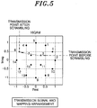
- FIG. 5 shows an example of a transmission signal of 16QAM, which is an example when the symbol mapping number is 3 and the scramble code is 5.
- the transmission symbol mapping number is converted into 6 by using Eq. 2. Therefore, with this symbol, the symbol mapping number 6 is mapped and outputted.
- FIGS. 6A and 6B respectively show states before and after scrambling of the transmission symbol number is applied to a reception point and reference points when the transmission signal of FIG. 5 is received.
- mapping points of reference points is shown in FIG. 6B , and it is apparent that a point having a minimum distance is 3. Therefore, when hard decision is made, it is obtained that the symbol mapping number of the transmission source of the reception signal is 3.
- the bit likelihood calculation process in the present embodiment is a method of calculating the likelihood by obtaining a distance from the reference point with respect to the equalization output of the mapping arrangement which does not have a lattice shape, and is different from maximum likelihood detection (MLD) which generates a replica using the channel estimation value and the reference mapping point and calculates a distance between the reception signal and the replica.
- MLD maximum likelihood detection
- FIG. 7 shows a configuration of an LLR calculation unit 30 in the case where the bit likelihood calculation process of the present embodiment is not applied.
- the LLR calculation unit 30 includes a phase rotation unit 31, bit LLR calculators 27a and 27b, a code converter 32, and a signal selector 33. Since the bit LLR calculators 27a and 27b are similar to the bit LLR calculator 27 described above, a redundant description will be omitted.
- the phase rotation unit 31 outputs a signal X ⁇ ' ( m ) obtained by performing phase rotation on the equalization output signal X ⁇ ( m ) using the scramble code N SCR (m) to the bit LLR calculator 27.
- the bit LLR calculator 27b calculates a bit LLR ⁇ QAM (m, b n ) from the input equalization output signal X ⁇ ( m ), for example, based on Eq. 7.
- FIG. 8 shows a distance calculation result in a bit LLR calculation process when the reception point in 16QAM of FIG. 6 is set to (-0.9, 0.3).
- a symbol whose bit is 0 and which has the minimum distance and a symbol whose bit is 1 and which has the minimum distance are selected.
- the code converter 32 performs code conversion according to the scramble code N SCR (m) on the bit LLR ⁇ QAM (m, b n ) inputted from the bit LLR calculator 27b, and outputs the code-converted bit LLR ⁇ ' QAM (m, b n ) to the signal selector 33.
- the signal selector 33 selects and outputs ⁇ PSK (m, b n ) if the modulation scheme is PSK, and selects and outputs ⁇ ' QAM (m, b n ) if the modulation scheme is QAM.
- FIG. 10 shows a bit LLR calculation result according to the first embodiment (scrambling the reference point symbol mapping number). It can be seen from both results that the same calculation result is obtained. In the case of applying the first embodiment, it is unnecessary to classify the process into PSK and QAM cases and to select the output as shown in FIG. 7 .
- the deinterleaver 28 rearranges the input bit LLR arranged by the interleaver 12 in the original arrangement order, and outputs it to the error correction decoder 29.
- the error correction decoder 29 performs error correction decoding such as Viterbi algorithm decoding on the input bit LLR, and outputs an error correction result.
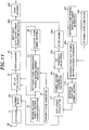
- FIG. 11 shows a configuration of a wireless communication device according to a second example of the present invention.
- a wireless communication device 200 comprises a wireless transmitter which includes an error correction encoder 11, an interleaver 12, a serial/parallel converter 13, a symbol mapping number converter 14, a scramble code generator 15, a transmission symbol mapping number converter 16, a symbol mapping unit 17, a modulator 18, and a transmission antenna 19, and a wireless receiver which includes a reception antenna 20, a detector 21, a SC/MMSE filter 201, a reference point symbol mapping number generator 23, a scramble code generator 24, a reference point transmission symbol mapping number generator 25, a reference point symbol mapping unit 26, a bit LLR calculator 27, a deinterleaver 28, a soft-input soft-output error correction decoder 202, a hard decision unit 203, an interleaver 204, a bit probability calculator 205, a symbol mapping probability calculator 206, a reference point symbol mapping number generator 207, a scramble code generator 208, a reference point soft
- the reception antenna 20, the detector 21, the reference point symbol mapping number generator 23, the scramble code generator 24, the reference point transmission symbol mapping number generator 25, the reference point symbol mapping unit 26, the bit LLR calculator 27, and the deinterleaver 28 are the same as those in the first embodiment, a description thereof will be omitted.
- the SC/MMSE filter 201 estimates a channel between transmission and reception from the input reception signal, generates a reference point of an interference component included in the reception signal from the channel estimation result and the input soft symbol, subtracts it from the reception signal, performs equalization based on the MMSE criterion, and outputs an equalization output to the bit LLR calculator 27.
- the soft-input soft-output error correction decoder 202 performs soft-input soft-output error correction decoding on the input bit LLR based on, for example, a soft output Viterbi algorithm (SOVA) or Bahl-Cocke-Jelinek-Raviv (BCJR) algorithm, and outputs the decoding result to the hard decision unit 203 and the interleaver 204.
- SOVA soft output Viterbi algorithm
- BCJR Bahl-Cocke-Jelinek-Raviv
- the hard decision unit 203 performs hard decision to output 0 if a sign of the input bit LLR is positive and to output 1 if it is negative, and outputs the decision result.
- the interleaver 204 arranges the input bit LLR in the same order as the interleaver 12, and outputs it to the bit probability calculator 205.
- the bit probability calculator 205 calculates a bit probability from the input bit LLR and outputs the bit probability to the symbol mapping probability calculator 206.
- the symbol mapping probability calculator 206 calculates a symbol mapping probability P i (m) using the input bit probabilities p 0 (m, b n ) and p 1 (m, b n ), and outputs it to the soft symbol calculator 211.
- the reference point symbol mapping number generator 207 has the same function as the reference point symbol mapping number generator 23, generates an integer (reference point symbol mapping number) of 0 .. Q-1, where Q represents the number of mapping points that can be obtained by the modulation scheme, and outputs it to the reference point soft symbol mapping number converter 209.
- Q represents the number of mapping points that can be obtained by the modulation scheme
- Q represents the number of mapping points that can be obtained by the modulation scheme
- the scramble code generator 208 has the same function as the scramble code generator 15 and the scramble code generator 24, and outputs the generated scramble code bit sequence to the reference point soft symbol mapping number converter 209.
- the reference point soft symbol mapping number converter 209 has the same function as the transmission symbol mapping number converter 16 and the reference point transmission symbol mapping number generator 25, generates a reference point transmission, symbol mapping number from the input reference point symbol mapping number and the scramble code bit sequence, and outputs it to the reference point soft symbol mapping unit 210.
- the reference point soft symbol mapping unit 210 has the same function as the symbol mapping unit 17 and the reference point symbol mapping unit 26, selects a predetermined mapping point using the input reference point transmission soft symbol mapping number, and outputs it to the soft symbol calculator 211.
- the soft symbol calculator 211 calculates a soft symbol using the input symbol mapping probability Pi(m) and the reference point symbol mapping output S q (m), and outputs the calculation result to the SC/MMSE filter 201.
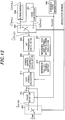
- FIG. 12 shows a configuration of soft symbol calculation when the second embodiment is not applied.
- the soft symbol calculation configuration of FIG. 12 includes the interleaver 204, a code converter 401, a signal selector 402, the bit probability calculator 205, the symbol mapping probability calculator 206, the reference point symbol mapping number generator 207, the scramble code generator 208, the reference point soft symbol mapping unit 210, the soft symbol calculator 211, a phase rotation unit 403, and a signal selector 404.
- the interleaver 204, the bit probability calculator 205, the symbol mapping probability calculator 206, the reference point symbol mapping number generator 207, the scramble code generator 208, the reference point soft symbol mapping unit 210, and the soft symbol calculator 211 are the same as those in the second embodiment, and thus a description thereof will be omitted.
- the code converter 401 has the same function as the code converter 32, performs code conversion according to the input scramble code N SCR (m) on the input bit LLR L e D (m, b' n ), and outputs the code-converted bit LLR Le 'D (m, b' n ) to the signal selector 402.
- the signal selector 402 Upon receiving the input bit LLR L e D (m, b' n ) and the code-converted bit LLR L e 'D (m, b' n ), depending on the modulation scheme, the signal selector 402 selects L e D (m, b' n ) if the modulation scheme is PSK and selects L e 'D (m, b' n ) if the modulation scheme is QAM, and outputs it to the bit probability calculator 205.
- the phase rotation unit 403 has the same function as the phase rotation unit 31, performs phase rotation according to the scramble code N SCR (m) on the input soft symbol S ⁇ ' ( m ), and outputs the phase-rotated soft symbol S ⁇ ROT ′ m to the signal selector 404.
- the signal selector 404 Upon receiving the input soft symbol S ⁇ ' ( m ) and the phase-rotated soft symbol S ⁇ ROT ′ m , depending on the modulation scheme, the signal selector 404 selects S ⁇ ROT ′ m if the modulation scheme is PSK and selects S ⁇ ' ( m ) if the modulation scheme is QAM, and outputs it.
- the second embodiment described above by receiving the transmission signal in which the symbol mapping number is scrambled on the transmission side and, when computing a soft symbol used for turbo equalization, generating a reference point signal by scrambling the reference point symbol mapping number, it is possible to calculate a soft symbol. Further, in the case where the second embodiment is not applied, code conversion and phase rotation are required, but the present invention does not require them and can realize a reduction in implementation scale.
- the present invention is particularly suitable for a wireless communication system defined by MIL-STD-188-110B, but is not limited thereto.
- the present invention can be applied to various types of wireless communication systems that perform wireless communication using white space.
Landscapes
- Engineering & Computer Science (AREA)
- Signal Processing (AREA)
- Computer Networks & Wireless Communication (AREA)
- Physics & Mathematics (AREA)
- Probability & Statistics with Applications (AREA)
- Theoretical Computer Science (AREA)
- Error Detection And Correction (AREA)
- Digital Transmission Methods That Use Modulated Carrier Waves (AREA)
- Power Engineering (AREA)
Description
- The present invention relates to a wireless communication device and method, and more particularly, to a wireless communication device and method for decoding data by calculating a soft symbol from a reception signal in which codes are interleaved and modulation symbol points are scrambled.
- For example, as specified in
Non-patent Document 1 "Department of Defense Interface Standard MIL-STD-188 110B Interoperability and Performance Standards for Data Modems" in baseband signal processing on the transmission side, a modulation bit sequence x(m) (m being a symbol number in a time direction) subjected to error correction encoding and interleaving is converted into a symbol mapping number N(m). Then, it is scrambled using a predetermined scramble code NSCR(m), and converted into a transmission symbol number NTX(m). Then, it is subjected to phase-shift keying (PSK) modulation or quadrature amplitude modulation (QAM) based on the mapping rule for data transmission. - In addition, in Appendix C of
Non-Patent Document 1, QPSK (quadrature-PSK), 8PSK, 16QAM, 32QAM, and 64QAM are defined as modulation schemes to be used, and scrambling is defined as follows. - In PSK, scrambling is represented by the following equation:

FIG. 1 shows the transmission symbol mapping number of PSK and its arrangement. It can be seen fromFIG. 1 and Eq. 1 that PSK scrambling is phase rotation by (π/4)*NSCR(m). - In QAM, scrambling is represented by the following equation:

FIG. 2 , the QAM symbol mapping points of MIL-STD-188-110B Appendix C are arranged in a shape (12/4 star QAM) which is not a general lattice shape. - When performing hard decision in equalization decision processing, descrambling may be performed on the hard-decided received bit sequence by performing a reverse operation of the scrambling of each modulation scheme.
- In
Patent Document 1 "Japanese Patent Application Publication No.2013-42444 - Further, as the QAM descrambling method, there is a method that is faithful to the principle of calculating a bit likelihood and then performing code conversion (equivalent to XOR operation) with reference to the scramble code.
- However, in a demodulation process for QAM as in
Non-patent Document 1, descrambling cannot be realized by simply manipulating an amplitude and/or a phase. Also, when dealing with a soft decision value and/or likelihood, it is necessary to calculate the likelihood in the case where all the symbol points are descrambled. In order to be able to process the QAM ofNon-patent Document 1 in a wireless receiver ofPatent Document 1, a correspondence table of all the combinations that can be obtained from all reference points and all scramble patterns is stored in the ROM and referred to. - In
Patent Document 2,US 2013/0044841 A1, published on Feb. 21, 2013 (a family member of Patent Document 1), further discloses a method in which at the receiver, the generated first replica signal is phase rotated based on the scramble sequence, thereby a second replica signal is generated. This second replica signal is used for calculating a log-likelihood ratio for the received and equalized signal. - The article "Low-Complexity MMSE Turbo Equalization: A Possible Solution for EDGE" by Christophe Laot et. al., IEEE Transactions on Wireless Communications, Vol. 4, , discloses a receiving method comprising iterative equalization and SISO demapping.
- In view of the above, the present invention provides a technique for obtaining a reference point using a transmission symbol number obtained by scrambling a symbol number when generating the reference point, thereby realizing demodulation and soft symbol calculation for both PSK and QAM with simple implementation.
- In accordance with an aspect of the present invention, there is provided a wireless communication system including: a transmission side baseband signal processing unit which includes:
- a means for converting a modulation bit sequence into a symbol mapping number;
- a means for generating a scramble code for the symbol mapping number;
- a symbol mapping number converting means for scrambling the symbol mapping number using the scramble code to convert the symbol mapping number into a transmission symbol mapping number;
a means for performing mapping according to the transmission symbol mapping number and a corresponding modulation scheme; and - a modulation transmission means for converting an output of the mapping into a time signal and converting and transmitting the time signal into a transmission frequency, and
- a means for receiving and detecting a signal transmitted by the modulation transmission means,
- a channel equalization means for performing channel equalization on the detected signal;
- a means for generating a first reference point symbol mapping number for generating a reference point in the modulation scheme;
- a means for scrambling the first reference point symbol mapping number using the scramble code to convert the first reference point symbol mapping number into a first reference point transmission symbol mapping number;
- a first reference point mapping means for performing mapping according to the first reference point transmission symbol mapping number and the modulation scheme;
- a means for calculating a distance between an output of the first reference point mapping means and an output of the channel equalization means; and
- a means for calculating a bit likelihood by referring to the first reference point symbol mapping number and the distance, characterized in that the transmission side baseband signal processing unit further include a means for performing error correction encoding and a first interleaving means for performing interleaving on an error correction encoded signal and outputting an interleaved signal to the symbol mapping number converting means, and the reception side baseband signal processing unit further include a means for deinterleaving the bit likelihood, a means for performing soft-input soft-output error correction decoding on the deinterleaved signal, a second interleaving means for applying the same interleaving pattern as the first interleaving means to the soft-input soft-output error correction decoded output, a means for converting a bit likelihood output from the second interleaving means into a bit probability, a symbol mapping probability calculating means for calculating a symbol mapping probability from the bit probability based on the modulation scheme, a means for generating a second reference point symbol mapping number for soft symbol calculation, a means for generating a second reference point transmission symbol mapping number using the scramble code for the second reference point symbol mapping number, a second reference point mapping means for performing mapping according to the second reference point transmission symbol mapping number and the modulation scheme, a soft symbol calculating means for calculating a soft symbol from an output of the symbol mapping probability calculating means and an output of the second reference point mapping means, and a turbo equalization means for feeding back an output of the soft symbol calculating means to the channel equalization means.
- In accordance with another aspect of the present invention, there is provided a wireless communication method including:
- on a transmission side,
- converting a modulation bit sequence into a predetermined symbol mapping number;
- generating a scramble code for the symbol mapping number;
- scrambling the symbol mapping number using the scramble code to convert the symbol mapping number into a transmission symbol mapping number;
- performing mapping according to the transmission symbol mapping number and a corresponding modulation scheme; and
- converting an output of the mapping into a time signal and converting and transmitting the time signal into a transmission frequency, and further including:
- on a reception side,
- receiving and detecting the transmitted signal;
- performing channel equalization or its equivalent process on the detected signal;
- generating a first reference point symbol mapping number for generating a reference point in the modulation scheme;
- scrambling the first reference point symbol mapping number using the scramble code to convert the first reference point symbol mapping number into a first reference point transmission symbol mapping number;
- performing mapping according to the first reference point transmission symbol mapping number and the modulation scheme;
- calculating a distance between an output of the mapping and an output of the channel equalization; and
- calculating a bit likelihood by referring to the first reference point symbol mapping number and the distance, characterized in that the method further includes
- on the transmission side, performing error correction encoding and performing interleaving on an error correction encoded signal and outputting an interleaved signal to a symbol mapping number converting means by using a first interleaving means, the symbol mapping number converting means performing the step of scrambling the symbol mapping number and on the reception side deinterleaving the bit likelihood performing soft-input soft-output error correction decoding on the deinterleaved signal applying the same interleaving pattern as the first interleaving means to the soft-input soft-output error correction decoded output by using a second interleaving means converting a bit likelihood output from the second interleaving means into a bit probability calculating a symbol mapping probability from the bit probability based on the modulation scheme generating a second reference point symbol mapping number for soft symbol calculation generating a second reference point transmission symbol mapping number using the scramble code for the second reference point symbol mapping number performing mapping according to the second reference point transmission symbol mapping number and the modulation scheme to generate a reference point symbol mapping output calculating a soft symbol from the symbol mapping probability and the reference point symbol mapping output and feeding back the soft symbol for the channel equalization.
-
-
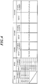
FIG. 1 is a diagram showing a symbol mapping point arrangement and a transmission symbol mapping number of PSK in MIL-STD-188-110B Appendix C. -
FIG. 2 is a diagram showing a symbol mapping point arrangement of QAM in MIL-STD-188-110B Appendix C. -
FIG. 3 is a functional block diagram showing a first embodiment of the present invention. -
FIG. 4 is a diagram showing an example of symbol mapping number conversion. -
FIG. 5 is a diagram for explaining an example of an operation according to a transmission signal and scrambling. -
FIGS. 6A and 6B are diagrams for explaining an example of a reference point according to a reception signal and scrambling. -
FIG. 7 shows a functional block diagram of bit LLR calculation when the present invention is not applied. -
FIG. 8 shows a result of calculating a distance between the reception point and each reference point inFIG. 6 . -
FIG. 9 shows a bit LLR calculation result when the present invention is not applied. -
FIG. 10 shows a bit LLR calculation result when the present invention is applied. -
FIG. 11 is a functional block diagram showing a second embodiment according to the claimed invention. -
FIG. 12 is a functional block diagram of soft symbol calculation when the present invention is not applied. - Hereinafter, embodiment of the present invention will be described in detail with reference to the accompanying drawings.
-
FIG. 3 shows a configuration of awireless communication device 1 according to a first embodiment. Thewireless communication device 1 includes anerror correction encoder 11, aninterleaver 12, a serial/parallel converter 13, a symbolmapping number converter 14, ascramble code generator 15, a transmission symbolmapping number converter 16, asymbol mapping unit 17, amodulator 18, atransmission antenna 19, areception antenna 20, adetector 21, achannel equalizer 22, a reference point symbolmapping number generator 23, ascramble code generator 24, a reference point transmission symbolmapping number generator 25, a reference pointsymbol mapping unit 26, abit LLR calculator 27, adeinterleaver 28, and anerror correction decoder 29. - The
error correction encoder 11 performs error correction encoding such as convolutional encoding on an input information bit sequence, and outputs it to theinterleaver 12. - The
interleaver 12 arranges the input bit sequence in a predetermined order, and outputs it to the serial/parallel converter 13. - The serial/
parallel converter 13 bundles bits of the input bit sequence corresponding to each modulation bit number of a predetermined modulation scheme, and outputs it to the transmission symbol mapping number converter. For example, every 2 bits are processed in QPSK, and every 3 bits are processed in 8PSK. - The symbol
mapping number converter 14 converts the input modulation bit sequence into a symbol mapping point number according to a predetermined conversion rule, and outputs it to the transmission symbolmapping number converter 16. As the conversion rule of the symbol mapping point, for example, in MIL-STD-188-110B Appendix C, conversion as shown inFIG. 4 is performed. - The
scramble code generator 15 outputs the scramble code bit sequence of the number of bits according to the predetermined modulation scheme to the transmission symbolmapping number converter 16. The scramble code bit sequence uses, for example, an output according to a predetermined cut-out rule of a Pseudo-random Noise (PN) generator. - The transmission symbol
mapping number converter 16, for example, as described in the Background of the Invention, when the symbol mapping number is N(m) and the scramble code is NSCR(m), calculates a transmission symbol mapping number NTX(m) using Eq. 1 or Eq. 2, and outputs the transmission symbol mapping number NTX(m) to thesymbol mapping unit 17. - The
symbol mapping unit 17 selects a predetermined symbol mapping point using the input transmission symbol mapping number NTX(m), and outputs the selected symbol mapping point to themodulator 18. - The
modulator 18 converts the input mapping output into a time signal, converts the time signal into a transmission frequency, and outputs it to thetransmission antenna 19. - The
transmission antenna 19 transmits the input modulation signal to a wireless transmission space. - The
reception antenna 20 receives the transmission signal from the wireless transmission space and outputs it to thedetector 21. - The
detector 21 detects the input signal, converts it into a frequency signal, and outputs it to thechannel equalizer 22. - The
channel equalizer 22 estimates a channel distortion between transmission and reception of the input reception frequency signal, corrects it, and outputs it to thebit LLR calculator 27. For channel equalization, when the reception signal is Y(m), the estimated channel between transmission and reception is H^(m), and an equalization output is X^(m), channel equalization is performed by using, for example, Eq. 3 or Eq. 4 according to the minimum mean square error (MMSE) criterion.

- The reference point symbol
mapping number generator 23 generates an integer (reference point symbol mapping number) of 0 .. Q-1, where Q represents the number of mapping points that can be obtained by the modulation scheme, and outputs it to the reference point transmission symbolmapping number generator 25 and thebit LLR calculator 27. For example, a register value prepared in advance, a read value of a ROM, and a counter value are used for number generation. - The
scramble code generator 24 has the same function as thescramble code generator 15, and outputs the generated scramble code bit sequence to the reference point transmission symbolmapping number generator 25. - The reference point transmission symbol
mapping number generator 25 has the same function as the transmission symbolmapping number converter 16, generates a reference point transmission symbol mapping number from the input reference point symbol mapping number and the scramble code bit sequence, and outputs it to the reference pointsymbol mapping unit 26. - The reference point
symbol mapping unit 26 has the same function as thesymbol mapping unit 17, selects a predetermined mapping point using the input reference point transmission symbol mapping number, and outputs it to thebit LLR calculator 27. - The
bit LLR calculator 27 calculates a bit likelihood using the input channel equalization output, the reference point mapping output and the reference point symbol mapping number, and outputs the bit likelihood to thedeinterleaver 28. Hereinafter, the bit likelihood calculation in addition to the transmission-side processing and the reference point generation will be described. -
FIG. 5 shows an example of a transmission signal of 16QAM, which is an example when the symbol mapping number is 3 and the scramble code is 5. The transmission symbol mapping number is converted into 6 by using Eq. 2. Therefore, with this symbol, thesymbol mapping number 6 is mapped and outputted. -
FIGS. 6A and 6B respectively show states before and after scrambling of the transmission symbol number is applied to a reception point and reference points when the transmission signal ofFIG. 5 is received. - First, hard decision of the reception signal will be considered. In the case where the present invention is not applied, an arrangement of mapping points of reference points is shown in
FIG. 6A , and it is apparent that a point having a minimum distance is 6. Therefore, when hard decision is made, the transmission symbol mapping number of a transmission source of the reception signal is 6. When 6 is descrambled, 3 is obtained, which coincides with the symbol mapping number of the transmission source. - In the case where the present invention is applied, an arrangement of mapping points of reference points is shown in
FIG. 6B , and it is apparent that a point having a minimum distance is 3. Therefore, when hard decision is made, it is obtained that the symbol mapping number of the transmission source of the reception signal is 3. - Next, calculation of a soft decision bit likelihood will be considered. As mentioned above, since the mapping arrangement of MIL-STD-188-110B Appendix C does not have a lattice shape, a value of a real part or an imaginary part of the equalization output cannot be used as a likelihood, and thus, a distance from the reference point is measured to calculate the likelihood. Here, a bit log likelihood ratio (LLR) is considered. The bit LLR λ(m, bn) is calculated, for example, by the following equation:


- Eq. 5 can be approximated to the following equation:

- Therefore, it is calculated by using the minimum distance to 1 and the minimum distance to 0 with respect to each bit. The above method can be applied even if the mapping arrangement has a lattice shape. Further, a known method for finding the symbol having the minimum distance more efficiently than the full search can be utilized.
- The bit likelihood calculation process in the present embodiment is a method of calculating the likelihood by obtaining a distance from the reference point with respect to the equalization output of the mapping arrangement which does not have a lattice shape, and is different from maximum likelihood detection (MLD) which generates a replica using the channel estimation value and the reference mapping point and calculates a distance between the reception signal and the replica.
- For comparison,
FIG. 7 shows a configuration of an LLR calculation unit 30 in the case where the bit likelihood calculation process of the present embodiment is not applied. The LLR calculation unit 30 includes aphase rotation unit 31,bit LLR calculators code converter 32, and asignal selector 33. Since thebit LLR calculators bit LLR calculator 27 described above, a redundant description will be omitted. - The
phase rotation unit 31 outputs a signal X̂'(m) obtained by performing phase rotation on the equalization output signal X̂(m) using the scramble code NSCR(m) to thebit LLR calculator 27. The phase rotation is calculated, for example, by the following equation:
- On the other hand, in the case of QAM, the
bit LLR calculator 27b calculates a bit LLR λQAM(m, bn) from the input equalization output signal X̂(m), for example, based on Eq. 7. -
FIG. 8 shows a distance calculation result in a bit LLR calculation process when the reception point in 16QAM ofFIG. 6 is set to (-0.9, 0.3). In obtaining the LLR of each bit, a symbol whose bit is 0 and which has the minimum distance and a symbol whose bit is 1 and which has the minimum distance (in this example,symbol mapping numbers - The
code converter 32 performs code conversion according to the scramble code NSCR(m) on the bit LLR λQAM(m, bn) inputted from thebit LLR calculator 27b, and outputs the code-converted bit LLR λ'QAM(m, bn) to thesignal selector 33. The code conversion is performed, for example, according to the following equation:
- With regard to the input bit LLR λPSK(m, bn) and λ'QAM(m, bn), the
signal selector 33 selects and outputs λPSK(m, bn) if the modulation scheme is PSK, and selects and outputs λ'QAM(m, bn) if the modulation scheme is QAM. - Here,
FIG. 9 shows the LLR and code conversion output of each bit based on Eq. 7 if the reception point is (-0.9, 0.3) when the first embodiment is not applied. For simplicity of explanation, calculation was made with σ2 = 1. -
FIG. 10 shows a bit LLR calculation result according to the first embodiment (scrambling the reference point symbol mapping number). It can be seen from both results that the same calculation result is obtained. In the case of applying the first embodiment, it is unnecessary to classify the process into PSK and QAM cases and to select the output as shown inFIG. 7 . - Referring back to
FIG. 3 , thedeinterleaver 28 rearranges the input bit LLR arranged by theinterleaver 12 in the original arrangement order, and outputs it to theerror correction decoder 29. - The
error correction decoder 29 performs error correction decoding such as Viterbi algorithm decoding on the input bit LLR, and outputs an error correction result. - According to the first embodiment described above, by receiving the transmission signal in which the symbol mapping number is scrambled on the transmission side and generating the reference point by scrambling the reference point symbol mapping number, it is possible to calculate a soft decision value such as bit LLR.
-
FIG. 11 shows a configuration of a wireless communication device according to a second example of the present invention. A wireless communication device 200 according to the second embodiment comprises a wireless transmitter which includes anerror correction encoder 11, aninterleaver 12, a serial/parallel converter 13, a symbolmapping number converter 14, ascramble code generator 15, a transmission symbolmapping number converter 16, asymbol mapping unit 17, amodulator 18, and atransmission antenna 19, and a wireless receiver which includes areception antenna 20, adetector 21, a SC/MMSE filter 201, a reference point symbolmapping number generator 23, ascramble code generator 24, a reference point transmission symbolmapping number generator 25, a reference pointsymbol mapping unit 26, abit LLR calculator 27, adeinterleaver 28, a soft-input soft-outputerror correction decoder 202, ahard decision unit 203, aninterleaver 204, abit probability calculator 205, a symbolmapping probability calculator 206, a reference point symbolmapping number generator 207, ascramble code generator 208, a reference point soft symbolmapping number converter 209, a reference point softsymbol mapping unit 210, and asoft symbol calculator 211. The wireless receiver realizes iterative decoding using a soft symbol (soft decision value). - All the configurations (the
error correction encoder 11 to the transmission antenna 19) of the wireless transmitter are the same as those in the first embodiment and are not illustrated. - Also, among the configurations of the wireless receiver, since the
reception antenna 20, thedetector 21, the reference point symbolmapping number generator 23, thescramble code generator 24, the reference point transmission symbolmapping number generator 25, the reference pointsymbol mapping unit 26, thebit LLR calculator 27, and thedeinterleaver 28 are the same as those in the first embodiment, a description thereof will be omitted. - The SC/
MMSE filter 201 estimates a channel between transmission and reception from the input reception signal, generates a reference point of an interference component included in the reception signal from the channel estimation result and the input soft symbol, subtracts it from the reception signal, performs equalization based on the MMSE criterion, and outputs an equalization output to thebit LLR calculator 27. - The soft-input soft-output
error correction decoder 202 performs soft-input soft-output error correction decoding on the input bit LLR based on, for example, a soft output Viterbi algorithm (SOVA) or Bahl-Cocke-Jelinek-Raviv (BCJR) algorithm, and outputs the decoding result to thehard decision unit 203 and theinterleaver 204. - For example, the
hard decision unit 203 performs hard decision tooutput 0 if a sign of the input bit LLR is positive and tooutput 1 if it is negative, and outputs the decision result. - The
interleaver 204 arranges the input bit LLR in the same order as theinterleaver 12, and outputs it to thebit probability calculator 205. - The
bit probability calculator 205 calculates a bit probability from the input bit LLR and outputs the bit probability to the symbolmapping probability calculator 206. The calculation of the bit probability is performed, for example, when Le D(m, bn) refers to the error-corrected bit LLR, p0(m, bn) refers to the bit probability that the bit is 0, and p1(m, bn) refers to the bit probability that the bit is 1, by the following equations:

- The symbol
mapping probability calculator 206 calculates a symbol mapping probability Pi(m) using the input bit probabilities p0(m, bn) and p1(m, bn), and outputs it to thesoft symbol calculator 211. The calculation of the symbol mapping probability is performed, for example, by the following equation:

- The reference point symbol
mapping number generator 207 has the same function as the reference point symbolmapping number generator 23, generates an integer (reference point symbol mapping number) of 0 .. Q-1, where Q represents the number of mapping points that can be obtained by the modulation scheme, and outputs it to the reference point soft symbolmapping number converter 209. For example, a register value prepared in advance, a read value of a ROM, and a counter value are used for number generation. - The
scramble code generator 208 has the same function as thescramble code generator 15 and thescramble code generator 24, and outputs the generated scramble code bit sequence to the reference point soft symbolmapping number converter 209. - The reference point soft symbol
mapping number converter 209 has the same function as the transmission symbolmapping number converter 16 and the reference point transmission symbolmapping number generator 25, generates a reference point transmission, symbol mapping number from the input reference point symbol mapping number and the scramble code bit sequence, and outputs it to the reference point softsymbol mapping unit 210. - The reference point soft
symbol mapping unit 210 has the same function as thesymbol mapping unit 17 and the reference pointsymbol mapping unit 26, selects a predetermined mapping point using the input reference point transmission soft symbol mapping number, and outputs it to thesoft symbol calculator 211. - The
soft symbol calculator 211 calculates a soft symbol using the input symbol mapping probability Pi(m) and the reference point symbol mapping output Sq(m), and outputs the calculation result to the SC/MMSE filter 201. The calculation of the soft symbol S̃(m) is performed, for example, by the following equation:


-
FIG. 12 shows a configuration of soft symbol calculation when the second embodiment is not applied. The soft symbol calculation configuration ofFIG. 12 includes theinterleaver 204, acode converter 401, asignal selector 402, thebit probability calculator 205, the symbolmapping probability calculator 206, the reference point symbolmapping number generator 207, thescramble code generator 208, the reference point softsymbol mapping unit 210, thesoft symbol calculator 211, aphase rotation unit 403, and asignal selector 404. - The
interleaver 204, thebit probability calculator 205, the symbolmapping probability calculator 206, the reference point symbolmapping number generator 207, thescramble code generator 208, the reference point softsymbol mapping unit 210, and thesoft symbol calculator 211 are the same as those in the second embodiment, and thus a description thereof will be omitted. - The
code converter 401 has the same function as thecode converter 32, performs code conversion according to the input scramble code NSCR(m) on the input bit LLR Le D(m, b'n), and outputs the code-converted bit LLR Le'D(m, b'n) to thesignal selector 402. - Upon receiving the input bit LLR Le D(m, b'n) and the code-converted bit LLR Le 'D(m, b'n), depending on the modulation scheme, the
signal selector 402 selects Le D(m, b'n) if the modulation scheme is PSK and selects Le 'D(m, b'n) if the modulation scheme is QAM, and outputs it to thebit probability calculator 205. - The
phase rotation unit 403 has the same function as thephase rotation unit 31, performs phase rotation according to the scramble code NSCR(m) on the input soft symbol S̃'(m), and outputs the phase-rotated soft symbol
signal selector 404. - Upon receiving the input soft symbol S̃'(m) and the phase-rotated soft symbol

signal selector 404 selects
- As described above, when the second embodiment is not applied, two processes of code conversion and phase rotation are required.
- According to the second embodiment described above, by receiving the transmission signal in which the symbol mapping number is scrambled on the transmission side and, when computing a soft symbol used for turbo equalization, generating a reference point signal by scrambling the reference point symbol mapping number, it is possible to calculate a soft symbol. Further, in the case where the second embodiment is not applied, code conversion and phase rotation are required, but the present invention does not require them and can realize a reduction in implementation scale.
- Further, the present invention is particularly suitable for a wireless communication system defined by MIL-STD-188-110B, but is not limited thereto.
- The present invention can be applied to various types of wireless communication systems that perform wireless communication using white space.
-
- 11: error correction encoder
- 12: interleaver
- 13: serial/parallel converter
- 14: symbol mapping number converter
- 15: scramble code generator
- 16: transmission symbol mapping number converter
- 17: symbol mapping unit
- 18: modulator
- 19: transmission antenna
- 20: reception antenna
- 21: detector
- 22: channel equalizer
- 23: reference point symbol mapping number generator
- 24: scramble code generator
- 25: reference point transmission symbol mapping number generator
- 26: reference point symbol mapping unit
- 27: bit LLR calculator
- 28: deinterleaver
- 29: error correction decoder
- 201: SC/MMSE filter
- 202: soft-input soft-output error correction decoder
- 203: hard decision unit
- 204: interleaver
- 205: bit probability calculator
- 206: symbol mapping probability calculator
- 207: reference point symbol mapping number generator
- 208: scramble code generator
- 209: reference point soft symbol mapping number converter
- 210: reference point soft symbol mapping unit
- 211: soft symbol calculator
- 31: phase rotation unit
- 32: code converter
- 33: signal selector
- 401: code converter
- 402: signal selector
- 403: phase rotation unit
- 404: signal selector
Claims (2)
- A wireless communication system comprising:a transmission side baseband signal processing unit which includes:a means (14) for converting a modulation bit sequence into a symbol mapping number;a means (15) for generating a scramble code for the symbol mapping number;a symbol mapping number converting means (16) for scrambling the symbol mapping number using the scramble code to convert the symbol mapping number into a transmission symbol mapping number;a means (17) for performing mapping according to the transmission symbol mapping number and a corresponding modulation scheme; anda modulation transmission means (18, 19) for converting an output of the mapping into a time signal and converting and transmitting the time signal into a transmission frequency, anda reception side baseband signal processing unit which includes:a means (20, 21) for receiving and detecting a signal transmitted by the modulation transmission means (18, 19),a channel equalization means (22) for performing channel equalization on the detected signal;a means (23) for generating a first reference point symbol mapping number for generating a reference point in the modulation scheme;a means (25) for scrambling the first reference point symbol mapping number using the scramble code to convert the first reference point symbol mapping number into a first reference point transmission symbol mapping number;a first reference point mapping means (26) for performing mapping according to the first reference point transmission symbol mapping number and the modulation scheme;a means (27) for calculating a distance between an output of the first reference point mapping means (26) and an output of the channel equalization means (22);and a means (27) for calculating a bit likelihood by referring to the first reference point symbol mapping number and the distance, characterized in that
the transmission side baseband signal processing unit further includes:a means (11) for performing error correction encoding; anda first interleaving means (12) for performing interleaving on an error correction encoded signal and outputting an interleaved signal to the symbol mapping number converting means (16); andthe reception side baseband signal processing unit further includes:a means (28) for deinterleaving the bit likelihood; a means (29) for performing soft-input soft-output error correction decoding on the deinterleaved signal;a second interleaving means (204) for applying the same interleaving pattern as the first interleaving means (12) to the soft-input soft-output error correction decoded output;a means (205) for converting a bit likelihood output from the second interleaving means (204) into a bit probability;a symbol mapping probability calculating means (206) for calculating a symbol mapping probability from the bit probability based on the modulation scheme;a means (207) for generating a second reference point symbol mapping number for soft symbol calculation;a means (209) for generating a second reference point transmission symbol mapping number using the scramble code for the second reference point symbol mapping number;a second reference point mapping means (210) for performing mapping according to the second reference point transmission symbol mapping number and the modulation scheme;a soft symbol calculating means (211) for calculating a soft symbol from an output of the symbol mapping probability calculating means (206) and an output of the second reference point mapping means (210); anda turbo equalization means (201) for feeding back an output of the soft symbol calculating means (211) to the channel equalization means (22). - A wireless communication method comprising:on a transmission side,converting a modulation bit sequence into a predetermined symbol mapping number;generating a scramble code for the symbol mapping number;scrambling the symbol mapping number using the scramble code to convert the symbol mapping number into a transmission symbol mapping number;performing mapping according to the transmission symbol mapping number and a corresponding modulation scheme; andconverting an output of the mapping into a time signal and converting and transmitting the time signal into a transmission frequency, and further comprising:on a reception side,receiving and detecting the transmitted signal;performing channel equalization on the detected signal;generating a first reference point symbol mapping number for generating a reference point in the modulation scheme;scrambling the first reference point symbol mapping number using the scramble code to convert the first reference point symbol mapping number into a first reference point transmission symbol mapping number;performing mapping according to the first reference point transmission symbol mapping number and the modulation scheme;calculating a distance between an output of the mapping and an output of the channel equalization; andcalculating a bit likelihood by referring to the first reference point symbol mapping number and the distance, characterized in thatthe method further comprises:on the transmission side,performing error correction encoding; andperforming interleaving on an error correction encoded signal and outputting an interleaved signal to a symbol mapping number converting means (16) by using a first interleaving means (12), the symbol mapping number converting means (16) performing the step of scrambling the symbol mapping number, andon the reception side:deinterleaving the bit likelihood;performing soft-input soft-output error correction decoding on the deinterleaved signal;applying the same interleaving pattern as the first interleaving means (12) to the soft-input soft-output error correction decoded output by using a second interleaving means (204);converting a bit likelihood output from the second interleaving means (204) into a bit probability;calculating a symbol mapping probability from the bit probability based on the modulation scheme;generating a second reference point symbol mapping number for soft symbol calculation;generating a second reference point transmission symbol mapping number using the scramble code for the second reference point symbol mapping number;performing mapping according to the second reference point transmission symbol mapping number and the modulation scheme to generate a reference point symbol mapping output;calculating a soft symbol from the symbol mapping probability and the reference point symbol mapping output; andfeeding back the soft symbol for the channel equalization.
Applications Claiming Priority (2)
| Application Number | Priority Date | Filing Date | Title |
|---|---|---|---|
| JP2014186030 | 2014-09-12 | ||
| PCT/JP2015/074958 WO2016039236A1 (en) | 2014-09-12 | 2015-09-02 | Wireless communication device and method |
Publications (3)
| Publication Number | Publication Date |
|---|---|
| EP3193453A1 EP3193453A1 (en) | 2017-07-19 |
| EP3193453A4 EP3193453A4 (en) | 2018-05-02 |
| EP3193453B1 true EP3193453B1 (en) | 2019-11-06 |
Family
ID=55458985
Family Applications (1)
| Application Number | Title | Priority Date | Filing Date |
|---|---|---|---|
| EP15840188.5A Active EP3193453B1 (en) | 2014-09-12 | 2015-09-02 | Wireless communication device and method |
Country Status (4)
| Country | Link |
|---|---|
| US (1) | US10033480B2 (en) |
| EP (1) | EP3193453B1 (en) |
| JP (1) | JP6183983B2 (en) |
| WO (1) | WO2016039236A1 (en) |
Families Citing this family (7)
| Publication number | Priority date | Publication date | Assignee | Title |
|---|---|---|---|---|
| US10763995B2 (en) * | 2015-08-11 | 2020-09-01 | Telecom Italia S.P.A. | Receiver for wireless communication networks |
| US10305717B2 (en) * | 2016-02-26 | 2019-05-28 | VertoCOMM, Inc. | Devices and methods using the hermetic transform for transmitting and receiving signals using multi-channel signaling |
| EP3616198B1 (en) | 2017-04-24 | 2024-10-16 | Virginia Tech Intellectual Properties, Inc. | Radio signal identification, identification system learning, and identifier deployment |
| FI3619656T3 (en) | 2017-05-03 | 2025-03-14 | Virginia Tech Intellectual Properties Inc | Learning and deployment of adaptive wireless communications |
| US10686490B2 (en) * | 2017-09-28 | 2020-06-16 | Qualcomm Incorporated | Modulation spreading for wireless communications |
| JP6981708B2 (en) * | 2019-02-18 | 2021-12-17 | 学校法人玉川学園 | Information processing equipment |
| JP7582814B2 (en) * | 2019-10-29 | 2024-11-13 | 日本放送協会 | Symbol decision device and retransmission device |
Family Cites Families (5)
| Publication number | Priority date | Publication date | Assignee | Title |
|---|---|---|---|---|
| KR100641519B1 (en) * | 2000-07-10 | 2006-10-31 | 마츠시타 덴끼 산교 가부시키가이샤 | Multicarrier Communication Devices and Peak Power Suppression Methods |
| US20020150038A1 (en) | 2000-07-10 | 2002-10-17 | Atsushi Sumasu | Multi-carrier communication device and peak power suppressing method |
| JP2004364046A (en) * | 2003-06-05 | 2004-12-24 | Seiko Epson Corp | Phase modulation signal demodulator |
| JP2007074618A (en) * | 2005-09-09 | 2007-03-22 | Sony Corp | Wireless communication apparatus, wireless communication method, and computer program |
| JP5618944B2 (en) * | 2011-08-19 | 2014-11-05 | 株式会社東芝 | Wireless receiver |
-
2015
- 2015-09-02 WO PCT/JP2015/074958 patent/WO2016039236A1/en not_active Ceased
- 2015-09-02 EP EP15840188.5A patent/EP3193453B1/en active Active
- 2015-09-02 JP JP2016547401A patent/JP6183983B2/en active Active
-
2017
- 2017-02-16 US US15/434,237 patent/US10033480B2/en active Active
Non-Patent Citations (1)
| Title |
|---|
| None * |
Also Published As
| Publication number | Publication date |
|---|---|
| EP3193453A4 (en) | 2018-05-02 |
| JP6183983B2 (en) | 2017-08-23 |
| US10033480B2 (en) | 2018-07-24 |
| US20170163379A1 (en) | 2017-06-08 |
| WO2016039236A1 (en) | 2016-03-17 |
| JPWO2016039236A1 (en) | 2017-04-27 |
| EP3193453A1 (en) | 2017-07-19 |
Similar Documents
| Publication | Publication Date | Title |
|---|---|---|
| US10033480B2 (en) | Wireless communication device and method | |
| Xu et al. | A soft detector for spectrally efficient systems with non-orthogonal overlapped sub-carriers | |
| US8953696B2 (en) | Signal decoding systems | |
| EP2223483B1 (en) | Blind turbo channel estimation | |
| JP5955481B2 (en) | Soft decision value generation apparatus and soft decision value generation method | |
| EP2200240A1 (en) | Method and apparatus for near-optimal computation of bit soft information in multiple antenna communication systems with iterative detection and decoding | |
| US20070283211A1 (en) | System and method for communicating data using iterative equalizing and decoding and recursive inner code | |
| US8542724B1 (en) | Iterative joint minimum mean square error decision feedback equalizer and turbo decoder | |
| US20100074319A1 (en) | Decoding system for LDPC code concatenated with 4QAM-NR code | |
| CN104521204A (en) | Joint sequence estimation of symbol and phase with high tolerance of nonlinearity | |
| MXPA06010073A (en) | Iterative channel and interference estimation and decoding. | |
| US9853700B2 (en) | Wireless transmission system and reception device | |
| WO2020118123A1 (en) | Stochastic linear detection | |
| EP2680520B1 (en) | Method and apparatus for efficient MIMO reception with reduced complexity | |
| EP2346223B1 (en) | Calculation of log-likelihood ratios in a demodulator | |
| EP2362597B1 (en) | Process for performing log-likelihood-ratio clipping in a soft-decision near-ML detector, and detector for doing the same | |
| Turk et al. | Adaptive demodulation using rateless codes based on maximum a posteriori probability | |
| JPWO2017158725A1 (en) | Log likelihood ratio calculation circuit, receiving apparatus, and log likelihood ratio calculation method | |
| Jakubisin et al. | Performance, complexity, and receiver design for code-aided frame synchronization in multipath channels | |
| EP3337070B1 (en) | Demodulation and decoding | |
| US20130044841A1 (en) | Wireless receiving apparatus and method | |
| Mathews et al. | Performance of turbo coded FBMC based MIMO systems | |
| Du et al. | Sorting-Based Soft-Demapping Algorithm for LoRa Systems | |
| Ogundile et al. | A low complexity iterative channel estimation and decoding receiver based on reed-solomon PTA | |
| US9917723B2 (en) | Efficient methods and recursive/scalable circuit architectures for QAM symbol mean and variance estimations |
Legal Events
| Date | Code | Title | Description |
|---|---|---|---|
| STAA | Information on the status of an ep patent application or granted ep patent |
Free format text: STATUS: THE INTERNATIONAL PUBLICATION HAS BEEN MADE |
|
| PUAI | Public reference made under article 153(3) epc to a published international application that has entered the european phase |
Free format text: ORIGINAL CODE: 0009012 |
|
| STAA | Information on the status of an ep patent application or granted ep patent |
Free format text: STATUS: REQUEST FOR EXAMINATION WAS MADE |
|
| 17P | Request for examination filed |
Effective date: 20170301 |
|
| AK | Designated contracting states |
Kind code of ref document: A1 Designated state(s): AL AT BE BG CH CY CZ DE DK EE ES FI FR GB GR HR HU IE IS IT LI LT LU LV MC MK MT NL NO PL PT RO RS SE SI SK SM TR |
|
| AX | Request for extension of the european patent |
Extension state: BA ME |
|
| DAV | Request for validation of the european patent (deleted) | ||
| DAX | Request for extension of the european patent (deleted) | ||
| A4 | Supplementary search report drawn up and despatched |
Effective date: 20180406 |
|
| RIC1 | Information provided on ipc code assigned before grant |
Ipc: H04L 1/00 20060101ALI20180329BHEP Ipc: H03M 13/25 20060101ALI20180329BHEP Ipc: H03M 13/45 20060101AFI20180329BHEP Ipc: H04L 27/34 20060101ALI20180329BHEP |
|
| GRAP | Despatch of communication of intention to grant a patent |
Free format text: ORIGINAL CODE: EPIDOSNIGR1 |
|
| STAA | Information on the status of an ep patent application or granted ep patent |
Free format text: STATUS: GRANT OF PATENT IS INTENDED |
|
| INTG | Intention to grant announced |
Effective date: 20190412 |
|
| GRAS | Grant fee paid |
Free format text: ORIGINAL CODE: EPIDOSNIGR3 |
|
| GRAA | (expected) grant |
Free format text: ORIGINAL CODE: 0009210 |
|
| STAA | Information on the status of an ep patent application or granted ep patent |
Free format text: STATUS: THE PATENT HAS BEEN GRANTED |
|
| AK | Designated contracting states |
Kind code of ref document: B1 Designated state(s): AL AT BE BG CH CY CZ DE DK EE ES FI FR GB GR HR HU IE IS IT LI LT LU LV MC MK MT NL NO PL PT RO RS SE SI SK SM TR |
|
| REG | Reference to a national code |
Ref country code: GB Ref legal event code: FG4D |
|
| REG | Reference to a national code |
Ref country code: CH Ref legal event code: EP Ref country code: AT Ref legal event code: REF Ref document number: 1200197 Country of ref document: AT Kind code of ref document: T Effective date: 20191115 |
|
| REG | Reference to a national code |
Ref country code: IE Ref legal event code: FG4D |
|
| REG | Reference to a national code |
Ref country code: DE Ref legal event code: R096 Ref document number: 602015041343 Country of ref document: DE |
|
| REG | Reference to a national code |
Ref country code: NL Ref legal event code: MP Effective date: 20191106 |
|
| REG | Reference to a national code |
Ref country code: LT Ref legal event code: MG4D |
|
| PG25 | Lapsed in a contracting state [announced via postgrant information from national office to epo] |
Ref country code: GR Free format text: LAPSE BECAUSE OF FAILURE TO SUBMIT A TRANSLATION OF THE DESCRIPTION OR TO PAY THE FEE WITHIN THE PRESCRIBED TIME-LIMIT Effective date: 20200207 Ref country code: NO Free format text: LAPSE BECAUSE OF FAILURE TO SUBMIT A TRANSLATION OF THE DESCRIPTION OR TO PAY THE FEE WITHIN THE PRESCRIBED TIME-LIMIT Effective date: 20200206 Ref country code: BG Free format text: LAPSE BECAUSE OF FAILURE TO SUBMIT A TRANSLATION OF THE DESCRIPTION OR TO PAY THE FEE WITHIN THE PRESCRIBED TIME-LIMIT Effective date: 20200206 Ref country code: NL Free format text: LAPSE BECAUSE OF FAILURE TO SUBMIT A TRANSLATION OF THE DESCRIPTION OR TO PAY THE FEE WITHIN THE PRESCRIBED TIME-LIMIT Effective date: 20191106 Ref country code: PL Free format text: LAPSE BECAUSE OF FAILURE TO SUBMIT A TRANSLATION OF THE DESCRIPTION OR TO PAY THE FEE WITHIN THE PRESCRIBED TIME-LIMIT Effective date: 20191106 Ref country code: LT Free format text: LAPSE BECAUSE OF FAILURE TO SUBMIT A TRANSLATION OF THE DESCRIPTION OR TO PAY THE FEE WITHIN THE PRESCRIBED TIME-LIMIT Effective date: 20191106 Ref country code: PT Free format text: LAPSE BECAUSE OF FAILURE TO SUBMIT A TRANSLATION OF THE DESCRIPTION OR TO PAY THE FEE WITHIN THE PRESCRIBED TIME-LIMIT Effective date: 20200306 Ref country code: LV Free format text: LAPSE BECAUSE OF FAILURE TO SUBMIT A TRANSLATION OF THE DESCRIPTION OR TO PAY THE FEE WITHIN THE PRESCRIBED TIME-LIMIT Effective date: 20191106 Ref country code: SE Free format text: LAPSE BECAUSE OF FAILURE TO SUBMIT A TRANSLATION OF THE DESCRIPTION OR TO PAY THE FEE WITHIN THE PRESCRIBED TIME-LIMIT Effective date: 20191106 Ref country code: FI Free format text: LAPSE BECAUSE OF FAILURE TO SUBMIT A TRANSLATION OF THE DESCRIPTION OR TO PAY THE FEE WITHIN THE PRESCRIBED TIME-LIMIT Effective date: 20191106 |
|
| PG25 | Lapsed in a contracting state [announced via postgrant information from national office to epo] |
Ref country code: IS Free format text: LAPSE BECAUSE OF FAILURE TO SUBMIT A TRANSLATION OF THE DESCRIPTION OR TO PAY THE FEE WITHIN THE PRESCRIBED TIME-LIMIT Effective date: 20200306 Ref country code: RS Free format text: LAPSE BECAUSE OF FAILURE TO SUBMIT A TRANSLATION OF THE DESCRIPTION OR TO PAY THE FEE WITHIN THE PRESCRIBED TIME-LIMIT Effective date: 20191106 Ref country code: HR Free format text: LAPSE BECAUSE OF FAILURE TO SUBMIT A TRANSLATION OF THE DESCRIPTION OR TO PAY THE FEE WITHIN THE PRESCRIBED TIME-LIMIT Effective date: 20191106 |
|
| PG25 | Lapsed in a contracting state [announced via postgrant information from national office to epo] |
Ref country code: AL Free format text: LAPSE BECAUSE OF FAILURE TO SUBMIT A TRANSLATION OF THE DESCRIPTION OR TO PAY THE FEE WITHIN THE PRESCRIBED TIME-LIMIT Effective date: 20191106 |
|
| PG25 | Lapsed in a contracting state [announced via postgrant information from national office to epo] |
Ref country code: ES Free format text: LAPSE BECAUSE OF FAILURE TO SUBMIT A TRANSLATION OF THE DESCRIPTION OR TO PAY THE FEE WITHIN THE PRESCRIBED TIME-LIMIT Effective date: 20191106 Ref country code: DK Free format text: LAPSE BECAUSE OF FAILURE TO SUBMIT A TRANSLATION OF THE DESCRIPTION OR TO PAY THE FEE WITHIN THE PRESCRIBED TIME-LIMIT Effective date: 20191106 Ref country code: EE Free format text: LAPSE BECAUSE OF FAILURE TO SUBMIT A TRANSLATION OF THE DESCRIPTION OR TO PAY THE FEE WITHIN THE PRESCRIBED TIME-LIMIT Effective date: 20191106 Ref country code: RO Free format text: LAPSE BECAUSE OF FAILURE TO SUBMIT A TRANSLATION OF THE DESCRIPTION OR TO PAY THE FEE WITHIN THE PRESCRIBED TIME-LIMIT Effective date: 20191106 Ref country code: CZ Free format text: LAPSE BECAUSE OF FAILURE TO SUBMIT A TRANSLATION OF THE DESCRIPTION OR TO PAY THE FEE WITHIN THE PRESCRIBED TIME-LIMIT Effective date: 20191106 |
|
| REG | Reference to a national code |
Ref country code: DE Ref legal event code: R097 Ref document number: 602015041343 Country of ref document: DE |
|
| REG | Reference to a national code |
Ref country code: AT Ref legal event code: MK05 Ref document number: 1200197 Country of ref document: AT Kind code of ref document: T Effective date: 20191106 |
|
| PG25 | Lapsed in a contracting state [announced via postgrant information from national office to epo] |
Ref country code: SK Free format text: LAPSE BECAUSE OF FAILURE TO SUBMIT A TRANSLATION OF THE DESCRIPTION OR TO PAY THE FEE WITHIN THE PRESCRIBED TIME-LIMIT Effective date: 20191106 Ref country code: SM Free format text: LAPSE BECAUSE OF FAILURE TO SUBMIT A TRANSLATION OF THE DESCRIPTION OR TO PAY THE FEE WITHIN THE PRESCRIBED TIME-LIMIT Effective date: 20191106 |
|
| PLBE | No opposition filed within time limit |
Free format text: ORIGINAL CODE: 0009261 |
|
| STAA | Information on the status of an ep patent application or granted ep patent |
Free format text: STATUS: NO OPPOSITION FILED WITHIN TIME LIMIT |
|
| 26N | No opposition filed |
Effective date: 20200807 |
|
| PG25 | Lapsed in a contracting state [announced via postgrant information from national office to epo] |
Ref country code: SI Free format text: LAPSE BECAUSE OF FAILURE TO SUBMIT A TRANSLATION OF THE DESCRIPTION OR TO PAY THE FEE WITHIN THE PRESCRIBED TIME-LIMIT Effective date: 20191106 Ref country code: AT Free format text: LAPSE BECAUSE OF FAILURE TO SUBMIT A TRANSLATION OF THE DESCRIPTION OR TO PAY THE FEE WITHIN THE PRESCRIBED TIME-LIMIT Effective date: 20191106 |
|
| PG25 | Lapsed in a contracting state [announced via postgrant information from national office to epo] |
Ref country code: IT Free format text: LAPSE BECAUSE OF FAILURE TO SUBMIT A TRANSLATION OF THE DESCRIPTION OR TO PAY THE FEE WITHIN THE PRESCRIBED TIME-LIMIT Effective date: 20191106 |
|
| REG | Reference to a national code |
Ref country code: DE Ref legal event code: R119 Ref document number: 602015041343 Country of ref document: DE |
|
| PG25 | Lapsed in a contracting state [announced via postgrant information from national office to epo] |
Ref country code: MC Free format text: LAPSE BECAUSE OF FAILURE TO SUBMIT A TRANSLATION OF THE DESCRIPTION OR TO PAY THE FEE WITHIN THE PRESCRIBED TIME-LIMIT Effective date: 20191106 |
|
| REG | Reference to a national code |
Ref country code: CH Ref legal event code: PL |
|
| REG | Reference to a national code |
Ref country code: BE Ref legal event code: MM Effective date: 20200930 |
|
| PG25 | Lapsed in a contracting state [announced via postgrant information from national office to epo] |
Ref country code: LU Free format text: LAPSE BECAUSE OF NON-PAYMENT OF DUE FEES Effective date: 20200902 |
|
| PG25 | Lapsed in a contracting state [announced via postgrant information from national office to epo] |
Ref country code: FR Free format text: LAPSE BECAUSE OF NON-PAYMENT OF DUE FEES Effective date: 20200930 Ref country code: DE Free format text: LAPSE BECAUSE OF NON-PAYMENT OF DUE FEES Effective date: 20210401 |
|
| PG25 | Lapsed in a contracting state [announced via postgrant information from national office to epo] |
Ref country code: LI Free format text: LAPSE BECAUSE OF NON-PAYMENT OF DUE FEES Effective date: 20200930 Ref country code: IE Free format text: LAPSE BECAUSE OF NON-PAYMENT OF DUE FEES Effective date: 20200902 Ref country code: BE Free format text: LAPSE BECAUSE OF NON-PAYMENT OF DUE FEES Effective date: 20200930 Ref country code: CH Free format text: LAPSE BECAUSE OF NON-PAYMENT OF DUE FEES Effective date: 20200930 |
|
| PG25 | Lapsed in a contracting state [announced via postgrant information from national office to epo] |
Ref country code: TR Free format text: LAPSE BECAUSE OF FAILURE TO SUBMIT A TRANSLATION OF THE DESCRIPTION OR TO PAY THE FEE WITHIN THE PRESCRIBED TIME-LIMIT Effective date: 20191106 Ref country code: MT Free format text: LAPSE BECAUSE OF FAILURE TO SUBMIT A TRANSLATION OF THE DESCRIPTION OR TO PAY THE FEE WITHIN THE PRESCRIBED TIME-LIMIT Effective date: 20191106 Ref country code: CY Free format text: LAPSE BECAUSE OF FAILURE TO SUBMIT A TRANSLATION OF THE DESCRIPTION OR TO PAY THE FEE WITHIN THE PRESCRIBED TIME-LIMIT Effective date: 20191106 |
|
| PG25 | Lapsed in a contracting state [announced via postgrant information from national office to epo] |
Ref country code: MK Free format text: LAPSE BECAUSE OF FAILURE TO SUBMIT A TRANSLATION OF THE DESCRIPTION OR TO PAY THE FEE WITHIN THE PRESCRIBED TIME-LIMIT Effective date: 20191106 |
|
| PGFP | Annual fee paid to national office [announced via postgrant information from national office to epo] |
Ref country code: GB Payment date: 20250731 Year of fee payment: 11 |