EP3193430A1 - Motor and electric compressor - Google Patents
Motor and electric compressor Download PDFInfo
- Publication number
- EP3193430A1 EP3193430A1 EP17151275.9A EP17151275A EP3193430A1 EP 3193430 A1 EP3193430 A1 EP 3193430A1 EP 17151275 A EP17151275 A EP 17151275A EP 3193430 A1 EP3193430 A1 EP 3193430A1
- Authority
- EP
- European Patent Office
- Prior art keywords
- stator
- housing
- central axis
- motor
- recess
- Prior art date
- Legal status (The legal status is an assumption and is not a legal conclusion. Google has not performed a legal analysis and makes no representation as to the accuracy of the status listed.)
- Withdrawn
Links
Images





Classifications
-
- H—ELECTRICITY
- H02—GENERATION; CONVERSION OR DISTRIBUTION OF ELECTRIC POWER
- H02K—DYNAMO-ELECTRIC MACHINES
- H02K1/00—Details of the magnetic circuit
- H02K1/06—Details of the magnetic circuit characterised by the shape, form or construction
- H02K1/12—Stationary parts of the magnetic circuit
- H02K1/18—Means for mounting or fastening magnetic stationary parts on to, or to, the stator structures
- H02K1/185—Means for mounting or fastening magnetic stationary parts on to, or to, the stator structures to outer stators
-
- H—ELECTRICITY
- H02—GENERATION; CONVERSION OR DISTRIBUTION OF ELECTRIC POWER
- H02K—DYNAMO-ELECTRIC MACHINES
- H02K5/00—Casings; Enclosures; Supports
- H02K5/04—Casings or enclosures characterised by the shape, form or construction thereof
-
- H—ELECTRICITY
- H02—GENERATION; CONVERSION OR DISTRIBUTION OF ELECTRIC POWER
- H02K—DYNAMO-ELECTRIC MACHINES
- H02K1/00—Details of the magnetic circuit
- H02K1/06—Details of the magnetic circuit characterised by the shape, form or construction
- H02K1/12—Stationary parts of the magnetic circuit
- H02K1/20—Stationary parts of the magnetic circuit with channels or ducts for flow of cooling medium
Definitions
- the present invention relates to a motor and an electric compressor.
- An electric compressor includes a compression mechanism arranged in a housing and a motor for driving the compression mechanism.
- the motor has a stator and a rotor which rotates in the stator.
- the stator is formed by winding a laminated steel plate.
- the stator is fixed to an inner surface of the housing by shrink-fitting or press-fitting.
- a purpose of the present invention is to provide a motor and an electric compressor which can reduce strain deformation of a stator and can prevent deterioration in a motor efficiency.
- a motor comprising: a stator configured to be arranged in a housing; and a rotor configured to be arranged in the stator and to rotate around a central axis, wherein a housing recess is formed in a part of an inner surface of the housing in a direction parallel to the central axis and in a circumferential direction of the central axis, a bottom surface of the housing recess is opposed to a side surface of the stator via a gap, and the inner surface of the housing on the outer side of the housing recess is fixed to the side surface of the stator.
- a space is formed between the side surface of the stator and the inner surface of the housing by forming the housing recess in a part of the inner surface of the housing.
- a stator recess may be formed in a part of the side surface of the stator in the direction parallel to the central axis and in the circumferential direction of the central axis.
- the space is also formed around the stator by forming the stator recess in a part of the side surface of the stator. Therefore, the fastening force for acting on the stator is released and the strain deformation is reduced.
- a motor comprising: a stator configured to be arranged in a housing; and a rotor configured to be arranged in the stator and rotate around the central axis, wherein a stator recess is formed in a part of a side surface of the stator in a direction parallel to the central axis and in a circumferential direction of the central axis, a bottom surface of the stator recess is opposed to an inner surface of the housing via a gap, and the side surface of the stator on the outer side of the stator recess is fixed to the inner surface of the housing.
- the motor preferably comprises a rotation preventing mechanism configured to prevent rotation of the stator relative to the housing.
- the stator When a part of the stator is separated from the housing, the stator may rotate relative to the housing due to a reaction force of a rotation force of the rotor for acting on the stator.
- the rotation preventing mechanism By providing the rotation preventing mechanism, the rotation of the stator is suppressed, and the deterioration in the motor efficiency is suppressed.
- the stator preferably includes a first groove which is formed so as to extend in the direction parallel to the central axis in the side surface of the stator and through which oil is supplied, and the rotation preventing mechanism is provided on the outer side of a bottom surface of the first groove in the radiation direction of the central axis.
- the rotation preventing mechanism is provided on the inner side of the bottom surface of the first groove in the radiation direction of the central axis.
- the rotation preventing mechanism is provided on the outer side of the bottom surface of the first groove in the radiation direction of the central axis, and the deterioration in the magnetic flux characteristic of the stator and the deterioration in the motor efficiency are suppressed.
- the rotation preventing mechanism may include a pin member to be coupled with the stator.
- the pin member coupled with the stator effectively prevents the rotation of the stator relative to the housing.
- the stator preferably has an opening which is formed in the direction parallel to the central axis and in which the pin member is arranged, and the opening is provided on the outer side of the bottom surface of the first groove in the radiation direction of the central axis.
- the magnetic flux characteristic of the stator may be deteriorated when the opening in which the pin member is arranged is provided on the inner side of the bottom surface of the first groove in the radiation direction of the central axis.
- the opening in which the pin member is arranged is provided on the outer side of the bottom surface of the first groove in the radiation direction of the central axis, and the deterioration in the magnetic flux characteristic of the stator and the deterioration in the motor efficiency are suppressed.
- an electric compressor comprising: the motor described above; and a compression mechanism configured to be operated by power generated by the motor.
- the electric compressor comprises the motor of which deterioration in the motor efficiency is suppressed, an efficiency of an electric compressor is improved.
- a motor and an electric compressor are provided which can reduce strain deformation of a stator and can prevent deterioration in a motor efficiency.
- FIG. 1 is a cross sectional side view of an exemplary electric compressor 1 according to the present embodiment.
- the electric compressor 1 is a hermetic electric scroll compressor.
- the electric compressor 1 includes a housing 3, a motor 5 provided in the housing 3, a rotary shaft 19, and a compression mechanism 7 which is connected to the rotary shaft 19 and is operated by power generated by the motor 5.
- the rotary shaft 19 is provided in the housing 3 and rotates around a central axis CE by the power generated by the motor 5.
- the housing 3 is made of metal such as steel and aluminum.
- the housing 3 includes a cylindrical housing body 3a which extends in a direction parallel to the central axis CE, a bottom member 3b which closes a lower end of the housing body 3a, and a lid member 3c which closes an upper end of the housing body 3a.
- a suction pipe 9 is provided on the side of the housing body 3a. The suction pipe 9 introduces gas into the housing 3.
- a discharge pipe 11 is provided on the upper part of the lid member 3c. The discharge pipe 11 discharges gas compressed by the compression mechanism 7.
- An oil sump 14 where oil can be stored is provided on the bottom of the housing 3.
- a discharge cover 13 is provided between the housing body 3a and the lid member 3c. The discharge cover 13 divides a space in the housing 3 into a low pressure chamber 3L and a high pressure chamber 3H.
- the motor 5 includes a stator 15 arranged in the housing 3, a rotor 17 which is arranged in the stator 15 and rotates around the central axis CE, and a resin bobbin 51 connected to the stator 15.
- the stator 15 includes a laminated steel plate.
- the rotor 17 is connected to the rotary shaft 19.
- the resin bobbin 51 is used for forming a winding (coil) of the stator 15.
- the resin bobbins 51 are provided on the upper part and the lower part of the stator 15 and support a coil.
- the stator 15, the rotor 17, the resin bobbin 51, and the rotary shaft 19 are arranged in the low pressure chamber 3L of the housing 3.
- the motor 5 rotates the rotor 17 with electric power supplied from an external power source. For example, the rotor 17 rotates at a speed equal to or more than 90 rps.
- the rotation of the rotary shaft 19 rotates the rotor 17.
- An upper end of the rotary shaft 19 is rotatably supported by an upper bearing 22.
- a lower end of the rotary shaft 19 is rotatably supported by a lower bearing 23.
- an eccentric pin 25 is provided which is projected upwards along an eccentric shaft LE deflected to the central axis CE.
- the upper end of the rotary shaft 19 having the eccentric pin 25 is connected to the compression mechanism 7.
- the rotary shaft 19 and the eccentric pin 25 have an oil supply passage 27.
- the lower end of the rotary shaft 19 is arranged in the oil sump 14.
- An oil pump 29 provided at the lower end of the rotary shaft 19 supplies the oil stored in the oil sump 14 to the oil supply passage 27 of the rotary shaft 19 with the rotation of the rotary shaft 19.
- the upper bearing 22 is provided in a bearing member 21.
- the bearing member 21 is fixed to an inner wall surface of the housing body 3a.
- the bearing member 21 rotatably supports the rotary shaft 19 via the upper bearing 22.
- a recess 21a provided on an upper surface of the bearing member 21 houses a drive bush 37 and stores the oil supplied by the oil pump 29 via the oil supply passage 27.
- the oil stored in the recess 21a is supplied to the compression mechanism 7.
- An oil discharge passage 21c formed in the bearing member 21 discharges the oil stored in the recess 21a to a space 40 between an end face 21b of the bearing member 21 and the inner wall surface of the housing body 3a.
- the compression mechanism 7 includes a fixed scroll 33, an orbiting scroll 35, and the drive bush 37.
- the orbiting scroll 35 orbits.
- low-pressure gas introduced into the low pressure chamber 3L in the housing 3 via the suction pipe 9 is suctioned to a compression chamber between the fixed scroll 33 and the orbiting scroll 35 and also is compressed, by orbiting of the orbiting scroll 35.
- the compressed high-pressure gas is discharged from the fixed scroll 33 to the high pressure chamber 3H by opening the discharge cover 13 and is discharged to the outside of the housing 3 via the discharge pipe 11.
- a guide plate 31 is provided below the bearing member 21.
- the guide plate 31 forms a tunnel 41, which leads the oil discharged from the oil discharge passage 21c to the oil sump 14 of the housing 3, between the guide plate 31 and the inner wall surface of the housing body 3a.
- the oil in the oil sump 14 is pumped by the oil pump 29 and moves through the oil supply passage 27 formed in the rotary shaft 19. Then, the lower bearing 23 and the upper bearing 22 are lubricated with the oil.
- the drive bush 37 is lubricated with the oil discharged from the upper end of the oil supply passage 27. After that, the oil is stored in the recess 21a provided at the center of the upper surface of the bearing member 21. The oil which has been discharged from the oil supply passage 27 and excessively stored in the recess 21a is discharged from an exit of the oil discharge passage 21c provided on the end face 21b to the space 40 through the oil discharge passage 21c.
- the oil discharged from the oil discharge passage 21c to the space 40 is supplied to the tunnel 41 between the guide plate 31 and the inner wall surface of the housing body 3a. After passing through the tunnel 41, the oil supplied to the tunnel 41 passes through a first groove 43 provided on side surface of the stator 15 and is transmitted to the oil sump 14.
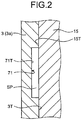
- FIG. 2 is an enlarged view of a part A in FIG. 1 .
- FIG. 3 is a schematic exploded perspective view of the motor 5 according to the present embodiment.
- a housing recess 71 is formed in a part of the inner surface of the housing 3 in the direction parallel to the central axis CE.
- the housing recess 71 is formed at a position opposed to the center of the stator 15 in the direction parallel to the central axis CE.
- the housing recess 71 is formed in a circumferential direction of the central axis CE.
- a bottom surface 71T of the housing recess 71 is opposed to a side surface 15T of the stator 15 via a gap.
- a space SP is formed between the housing recess 71 and the stator 15.
- the space SP is provided in the circumferential direction of the central axis CE so as to surround the stator 15.
- An inner surface 3T of the housing 3 outside the housing recess 71 is fixed to the side surface 15T of the stator 15.
- the stator 15 is fixed to the housing 3 by shrink-fitting.
- the stator 15 has the first grooves 43 which extend in the direction parallel to the central axis CE on the side surface of the stator 15.
- the plurality of first grooves 43 is provided in the circumferential direction of the central axis CE. As described above, the oil can pass through the first groove 43, and the oil passed through the first groove 43 is transmitted to the oil sump 14.
- the motor 5 has a rotation preventing mechanism 60 which prevents the rotation of the stator 15 relative to the housing 3.
- the rotation preventing mechanism 60 prevents the rotation of the stator 15 caused by a reaction force of the rotation force of the rotor 17 which acts on the stator 15.
- the space SP is formed between the stator 15 and the housing 3, and thus a part of the stator 15 is apart from the housing 3. That is, although the stator 15 is fixed to the housing 3 via the side surface 15T and the inner surface 3T, the stator 15 is not directly fixed to the housing 3 in the space SP. Therefore, when the rotation force of the rotor 17 is strong, the stator 15 may rotate relative to the housing 3 due to the reaction force of the rotation force of the rotor 17.
- the rotation preventing mechanism 60 prevents the rotation of the stator 15 relative to the housing 3.
- the rotation preventing mechanism 60 includes a pin member 61 for coupling the housing 3 with the stator 15.
- a hole 15H is formed in the stator 15 in the direction parallel to the central axis CE.
- the holes 15H is an opening in which the pin member 61 is arranged.
- a plurality of holes 15H (three holes in the example illustrated in FIG. 3 ) is provided in the circumferential direction of the central axis CE.
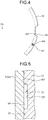
- FIG. 4 is a schematic diagram to describe a positional relationship between the stator 15 and the hole 15H according to the present embodiment. As illustrated in FIG. 4 , the hole 15H is provided on the outer side of a bottom surface 43T of the first groove 43 in a radiation direction of the central axis CE.
- magnetic flux characteristic of the stator 15 may be deteriorated when the hole 15H in which the pin member 61 is arranged is provided on the inner side of the bottom surface 43T of the first groove 43 in the radiation direction of the central axis CE.
- the hole 15H in which the pin member 61 is arranged is provided on the outer side of the bottom surface 43T of the first groove 43 in the radiation direction of the central axis CE, the deterioration in the magnetic flux characteristic of the stator 15 is suppressed, and the deterioration in the motor efficiency is suppressed.
- the space SP is formed between the side surface of the stator 15 and the inner surface of the housing 3 by forming the housing recess 71 in a part of the inner surface of the housing 3.
- the housing recess 71 is formed in the circumferential direction of the central axis CE, the space SP is formed around the stator 15. Therefore, the fastening force for acting on the stator 15 is effectively released, and the strain deformation of the stator 15 is reduced.
- the rotation of the stator 15 relative to the housing 3 is prevented by providing the rotation preventing mechanism 60. Therefore, the deterioration in the efficiency of the motor 5 is suppressed.
- the stator 15 has the first groove 43 through which the oil passes, and the rotation preventing mechanism 60 is provided on the outer side of the bottom surface 43T of the first groove 43 in the radiation direction of the central axis CE. This prevents the deterioration in the magnetic flux characteristic of the stator 15 and the deterioration in the motor efficiency.
- the rotation preventing mechanism 60 includes the pin member 61 to be coupled with the stator 15.
- the pin member 61 effectively prevents the rotation of the stator 15 relative to the housing 3.
- the stator 15 is fixed to the housing 3 by shrink-fitting.
- the stator 15 may be fixed to the housing 3 by welding.
- the stator 15 may be fixed to the housing 3 by caulking.
- the housing recess 71 is provided so as to be opposed to the center of the stator 15 in the direction parallel to the central axis CE.
- the housing recess 71 may be provided so as to be opposed to at least one of the upper part and the lower part of the stator 15.
- a plurality of housing recesses 71 may be provided in the direction parallel to the central axis CE.
- FIG. 5 is a cross sectional view of a partially enlarged housing 3 and stator 15 according to the present embodiment.
- FIG. 6 is a schematic exploded perspective view of a motor 5B having the stator 15 and resin bobbins 51 according to the present embodiment.
- a stator recess 72 is formed in a part of the side surface of the stator 15 in a direction parallel to a central axis CE.
- the stator recess 72 is formed at the center of the stator 15 in the direction parallel to the central axis CE.
- the stator recess 72 is formed in the circumferential direction of the central axis CE.
- a bottom surface 72T of the stator recess 72 is opposed to the inner surface 3T of the housing 3 via a gap.
- a space SP is formed between the stator recess 72 and the housing 3.
- the space SP is provided in the circumferential direction of the central axis CE so as to surround the stator 15.
- the stator 15 is fixed to the housing 3 by shrink-fitting.
- the motor 5B also includes a rotation preventing mechanism 60 which prevents the rotation of the stator 15 relative to the housing 3.
- the rotation preventing mechanism 60 includes a pin member 61 for coupling the housing 3 with the stator 15.
- the space SP is formed between the stator 15 and the housing 3 by forming the stator recess 72 in a part of the side surface of the stator 15. Similar to the above embodiment, the formation of the space SP reduces the strain deformation of the stator 15 and the deterioration in the motor efficiency. Also, since the stator recess 72 is formed in the circumferential direction of the central axis CE, the space SP is formed around the stator 15. Therefore, the fastening force for acting on the stator 15 is effectively released, and the strain deformation of the stator 15 is reduced.
- stator 15 may be fixed to the housing 3 by welding or caulking.
- stator recess 72 is provided at the center of the stator 15 in the direction parallel to the central axis CE.
- the stator recess 72 may be provided in at least one of the upper part and the lower part of the stator 15.
- the plurality of stator recesses 72 may be provided in the direction parallel to the central axis CE. This is similarly applied to the following embodiment.
- a third embodiment is described.
- the components which are the same as or similar to those in the above embodiment are denoted with the same reference numerals, and the description for the components is simplified or omitted.
- FIG. 7 is a schematic exploded perspective view of a stator 15 and resin bobbins 51 of a motor 5C according to the present embodiment.
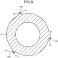
- FIG. 8 is a view on arrow B-B in FIG. 7 .
- a stator recess 72 is provided in the side surface of the stator 15.
- the stator 15 has a projecting member 75 which is projected outside from the bottom surface of the stator recess 72 in the radiation direction of the central axis CE.
- a recess 15R which is an opening where a pin member 61 is arranged is provided in the projecting member 75.
- a top end of the projecting member 75 is arranged on the inner side of the side surface of the stator 15, which has contact with the inner surface of the housing 3, in the radiation direction of the central axis CE.
- FIG. 9 is a schematic diagram of a relationship between a hole 15H and the recess 15R provided in the stator 15.
- the hole 15H is provided so as to pass through an upper surface 15a of the stator 15 and a lower surface 15b facing to the stator recess 72.
- the hole 15H is provided so as to pass through an upper surface 15c facing to the stator recess 72 and a lower surface 15d of the stator 15.
- the hole 15H corresponds to the recess 15R.
- the pin member 61 is arranged in the hole 15H and the recess 15R.
- the pin member 61 is more stably held by providing the recess 15R in addition to the hole 15H. Therefore, the rotation of the stator 15 is more effectively prevented by the pin member 61.
- both of the housing recess 71 and the stator recess 72 may be provided.
Landscapes
- Engineering & Computer Science (AREA)
- Power Engineering (AREA)
- Compressor (AREA)
- Iron Core Of Rotating Electric Machines (AREA)
- Applications Or Details Of Rotary Compressors (AREA)
- Motor Or Generator Frames (AREA)
Abstract
Description
- The present invention relates to a motor and an electric compressor.
- An electric compressor includes a compression mechanism arranged in a housing and a motor for driving the compression mechanism. The motor has a stator and a rotor which rotates in the stator. The stator is formed by winding a laminated steel plate. For example, as disclosed in Patent Literatures 1 and 2, the stator is fixed to an inner surface of the housing by shrink-fitting or press-fitting.
-
- Patent Literature 1: Japanese Laid-open Patent Publication No.
2006-296010 - Patent Literature 2: Japanese Laid-open Patent Publication No.
2012-082792 - When the stator is fixed by shrink-fitting, a large fastening force acts on the stator, and strain deformation may be generated in the stator. When the strain deformation is generated in the stator, magnetic characteristic of the stator is deteriorated, and a motor efficiency may be lowered.
- A purpose of the present invention is to provide a motor and an electric compressor which can reduce strain deformation of a stator and can prevent deterioration in a motor efficiency.
- According to the present invention, there is provided a motor comprising: a stator configured to be arranged in a housing; and a rotor configured to be arranged in the stator and to rotate around a central axis, wherein a housing recess is formed in a part of an inner surface of the housing in a direction parallel to the central axis and in a circumferential direction of the central axis, a bottom surface of the housing recess is opposed to a side surface of the stator via a gap, and the inner surface of the housing on the outer side of the housing recess is fixed to the side surface of the stator.
- According to the present invention, a space is formed between the side surface of the stator and the inner surface of the housing by forming the housing recess in a part of the inner surface of the housing. Even when the stator is fixed to the housing by shrink-fitting and the like, a fastening force for acting on the stator is released and strain deformation caused by the fastening force is reduced by forming the space. For example, even when the fastening force acts on and deforms the stator, the deformed part is escaped to the space. Accordingly, the strain deformation is reduced. Since the strain deformation of the stator is reduced, deterioration in a motor efficiency is suppressed. Also, since the housing recess is formed in the circumferential direction of the central axis, the space is formed around the stator. Therefore, the fastening force for acting on the stator is effectively released.
- According to the present invention, a stator recess may be formed in a part of the side surface of the stator in the direction parallel to the central axis and in the circumferential direction of the central axis.
- The space is also formed around the stator by forming the stator recess in a part of the side surface of the stator. Therefore, the fastening force for acting on the stator is released and the strain deformation is reduced.
- According to the present invention, there is provided a motor comprising: a stator configured to be arranged in a housing; and a rotor configured to be arranged in the stator and rotate around the central axis, wherein a stator recess is formed in a part of a side surface of the stator in a direction parallel to the central axis and in a circumferential direction of the central axis, a bottom surface of the stator recess is opposed to an inner surface of the housing via a gap, and the side surface of the stator on the outer side of the stator recess is fixed to the inner surface of the housing.
- Also, in the present invention, since a space is formed between the side surface of the stator and the inner surface of the housing, a fastening force for acting on the stator is released and strain deformation is reduced. Therefore, deterioration in a motor efficiency is suppressed.
- According to the present invention, the motor preferably comprises a rotation preventing mechanism configured to prevent rotation of the stator relative to the housing.
- When a part of the stator is separated from the housing, the stator may rotate relative to the housing due to a reaction force of a rotation force of the rotor for acting on the stator. By providing the rotation preventing mechanism, the rotation of the stator is suppressed, and the deterioration in the motor efficiency is suppressed.
- According to the present invention, the stator preferably includes a first groove which is formed so as to extend in the direction parallel to the central axis in the side surface of the stator and through which oil is supplied, and the rotation preventing mechanism is provided on the outer side of a bottom surface of the first groove in the radiation direction of the central axis.
- In a case where the first groove is provided in the stator, magnetic flux characteristic of the stator may be deteriorated when the rotation preventing mechanism is provided on the inner side of the bottom surface of the first groove in the radiation direction of the central axis. Thus the rotation preventing mechanism is provided on the outer side of the bottom surface of the first groove in the radiation direction of the central axis, and the deterioration in the magnetic flux characteristic of the stator and the deterioration in the motor efficiency are suppressed.
- According to the present invention, the rotation preventing mechanism may include a pin member to be coupled with the stator.
- The pin member coupled with the stator effectively prevents the rotation of the stator relative to the housing.
- According to the present invention, the stator preferably has an opening which is formed in the direction parallel to the central axis and in which the pin member is arranged, and the opening is provided on the outer side of the bottom surface of the first groove in the radiation direction of the central axis.
- In a case where the first groove is provided in the stator, the magnetic flux characteristic of the stator may be deteriorated when the opening in which the pin member is arranged is provided on the inner side of the bottom surface of the first groove in the radiation direction of the central axis. Thus the opening in which the pin member is arranged is provided on the outer side of the bottom surface of the first groove in the radiation direction of the central axis, and the deterioration in the magnetic flux characteristic of the stator and the deterioration in the motor efficiency are suppressed.
- According to the present invention, there is provided an electric compressor comprising: the motor described above; and a compression mechanism configured to be operated by power generated by the motor.
- According to the present invention, since the electric compressor comprises the motor of which deterioration in the motor efficiency is suppressed, an efficiency of an electric compressor is improved.
- According to the present invention, a motor and an electric compressor are provided which can reduce strain deformation of a stator and can prevent deterioration in a motor efficiency.
-
-
FIG. 1 is a cross sectional side view of an exemplary electric compressor according to a first embodiment. -
FIG. 2 is an enlarged view of a part A inFIG. 1 . -
FIG. 3 is a schematic exploded perspective view of a motor according to the first embodiment. -
FIG. 4 is a schematic diagram to describe a positional relationship between a stator and a hole according to the first embodiment. -
FIG. 5 is a cross sectional view of a partially enlarged housing and stator according to a second embodiment. -
FIG. 6 is a schematic exploded perspective view of a motor according to the second embodiment. -
FIG. 7 is a schematic exploded perspective view of a motor according to a third embodiment. -
FIG. 8 is a view on arrow B-B inFIG. 7 . -
FIG. 9 is a schematic diagram of a relationship between a hole and a recess provided in a stator according to a third embodiment. - Embodiments of the present invention are described below with reference to the drawings. However, the present invention is not limited to the embodiments. Components of each embodiment to be described below can be appropriately combined. There are cases where a part of the components is not used.
- A first embodiment is described.
FIG. 1 is a cross sectional side view of an exemplary electric compressor 1 according to the present embodiment. In the present embodiment, the electric compressor 1 is a hermetic electric scroll compressor. - As illustrated in
FIG. 1 , the electric compressor 1 includes ahousing 3, amotor 5 provided in thehousing 3, arotary shaft 19, and acompression mechanism 7 which is connected to therotary shaft 19 and is operated by power generated by themotor 5. Therotary shaft 19 is provided in thehousing 3 and rotates around a central axis CE by the power generated by themotor 5. - The
housing 3 is made of metal such as steel and aluminum. Thehousing 3 includes acylindrical housing body 3a which extends in a direction parallel to the central axis CE, abottom member 3b which closes a lower end of thehousing body 3a, and alid member 3c which closes an upper end of thehousing body 3a. Asuction pipe 9 is provided on the side of thehousing body 3a. Thesuction pipe 9 introduces gas into thehousing 3. Adischarge pipe 11 is provided on the upper part of thelid member 3c. Thedischarge pipe 11 discharges gas compressed by thecompression mechanism 7. Anoil sump 14 where oil can be stored is provided on the bottom of thehousing 3. Adischarge cover 13 is provided between thehousing body 3a and thelid member 3c. The discharge cover 13 divides a space in thehousing 3 into alow pressure chamber 3L and ahigh pressure chamber 3H. - The
motor 5 includes astator 15 arranged in thehousing 3, arotor 17 which is arranged in thestator 15 and rotates around the central axis CE, and aresin bobbin 51 connected to thestator 15. Thestator 15 includes a laminated steel plate. Therotor 17 is connected to therotary shaft 19. Theresin bobbin 51 is used for forming a winding (coil) of thestator 15. The resin bobbins 51 are provided on the upper part and the lower part of thestator 15 and support a coil. Thestator 15, therotor 17, theresin bobbin 51, and therotary shaft 19 are arranged in thelow pressure chamber 3L of thehousing 3. Themotor 5 rotates therotor 17 with electric power supplied from an external power source. For example, therotor 17 rotates at a speed equal to or more than 90 rps. The rotation of therotary shaft 19 rotates therotor 17. - An upper end of the
rotary shaft 19 is rotatably supported by anupper bearing 22. A lower end of therotary shaft 19 is rotatably supported by alower bearing 23. On the upper end of therotary shaft 19, aneccentric pin 25 is provided which is projected upwards along an eccentric shaft LE deflected to the central axis CE. The upper end of therotary shaft 19 having theeccentric pin 25 is connected to thecompression mechanism 7. - The
rotary shaft 19 and theeccentric pin 25 have anoil supply passage 27. The lower end of therotary shaft 19 is arranged in theoil sump 14. Anoil pump 29 provided at the lower end of therotary shaft 19 supplies the oil stored in theoil sump 14 to theoil supply passage 27 of therotary shaft 19 with the rotation of therotary shaft 19. - The
upper bearing 22 is provided in a bearingmember 21. The bearingmember 21 is fixed to an inner wall surface of thehousing body 3a. The bearingmember 21 rotatably supports therotary shaft 19 via theupper bearing 22. Arecess 21a provided on an upper surface of the bearingmember 21 houses adrive bush 37 and stores the oil supplied by theoil pump 29 via theoil supply passage 27. The oil stored in therecess 21a is supplied to thecompression mechanism 7. Anoil discharge passage 21c formed in the bearingmember 21 discharges the oil stored in therecess 21a to aspace 40 between anend face 21b of the bearingmember 21 and the inner wall surface of thehousing body 3a. - The
compression mechanism 7 includes a fixedscroll 33, an orbitingscroll 35, and thedrive bush 37. When themotor 5 is operated and therotary shaft 19 rotates, the orbitingscroll 35 orbits. In thecompression mechanism 7, low-pressure gas introduced into thelow pressure chamber 3L in thehousing 3 via thesuction pipe 9 is suctioned to a compression chamber between the fixedscroll 33 and the orbitingscroll 35 and also is compressed, by orbiting of the orbitingscroll 35. The compressed high-pressure gas is discharged from the fixedscroll 33 to thehigh pressure chamber 3H by opening thedischarge cover 13 and is discharged to the outside of thehousing 3 via thedischarge pipe 11. - A
guide plate 31 is provided below the bearingmember 21. Theguide plate 31 forms atunnel 41, which leads the oil discharged from theoil discharge passage 21c to theoil sump 14 of thehousing 3, between theguide plate 31 and the inner wall surface of thehousing body 3a. - In the operation of the electric compressor 1, the oil in the
oil sump 14 is pumped by theoil pump 29 and moves through theoil supply passage 27 formed in therotary shaft 19. Then, thelower bearing 23 and theupper bearing 22 are lubricated with the oil. Thedrive bush 37 is lubricated with the oil discharged from the upper end of theoil supply passage 27. After that, the oil is stored in therecess 21a provided at the center of the upper surface of the bearingmember 21. The oil which has been discharged from theoil supply passage 27 and excessively stored in therecess 21a is discharged from an exit of theoil discharge passage 21c provided on theend face 21b to thespace 40 through theoil discharge passage 21c. The oil discharged from theoil discharge passage 21c to thespace 40 is supplied to thetunnel 41 between theguide plate 31 and the inner wall surface of thehousing body 3a. After passing through thetunnel 41, the oil supplied to thetunnel 41 passes through afirst groove 43 provided on side surface of thestator 15 and is transmitted to theoil sump 14. -
FIG. 2 is an enlarged view of a part A inFIG. 1 .FIG. 3 is a schematic exploded perspective view of themotor 5 according to the present embodiment. - As illustrated in
FIGS. 1 to 3 , ahousing recess 71 is formed in a part of the inner surface of thehousing 3 in the direction parallel to the central axis CE. In the present embodiment, thehousing recess 71 is formed at a position opposed to the center of thestator 15 in the direction parallel to the central axis CE. Thehousing recess 71 is formed in a circumferential direction of the central axis CE. - A
bottom surface 71T of thehousing recess 71 is opposed to aside surface 15T of thestator 15 via a gap. - A space SP is formed between the
housing recess 71 and thestator 15. The space SP is provided in the circumferential direction of the central axis CE so as to surround thestator 15. Aninner surface 3T of thehousing 3 outside thehousing recess 71 is fixed to theside surface 15T of thestator 15. In the present embodiment, thestator 15 is fixed to thehousing 3 by shrink-fitting. - As illustrated in
FIGS. 1 and3 , thestator 15 has thefirst grooves 43 which extend in the direction parallel to the central axis CE on the side surface of thestator 15. The plurality offirst grooves 43 is provided in the circumferential direction of the central axis CE. As described above, the oil can pass through thefirst groove 43, and the oil passed through thefirst groove 43 is transmitted to theoil sump 14. - In the present embodiment, the
motor 5 has arotation preventing mechanism 60 which prevents the rotation of thestator 15 relative to thehousing 3. Therotation preventing mechanism 60 prevents the rotation of thestator 15 caused by a reaction force of the rotation force of therotor 17 which acts on thestator 15. In the present embodiment, the space SP is formed between thestator 15 and thehousing 3, and thus a part of thestator 15 is apart from thehousing 3. That is, although thestator 15 is fixed to thehousing 3 via theside surface 15T and theinner surface 3T, thestator 15 is not directly fixed to thehousing 3 in the space SP. Therefore, when the rotation force of therotor 17 is strong, thestator 15 may rotate relative to thehousing 3 due to the reaction force of the rotation force of therotor 17. Therotation preventing mechanism 60 prevents the rotation of thestator 15 relative to thehousing 3. - In the present embodiment, the
rotation preventing mechanism 60 includes apin member 61 for coupling thehousing 3 with thestator 15. Ahole 15H is formed in thestator 15 in the direction parallel to the central axis CE. Theholes 15H is an opening in which thepin member 61 is arranged. By arranging thepin member 61 in thehole 15H and fixing thepin member 61 to thehousing 3, the rotation of thestator 15 relative to thehousing 3 is prevented. - In the present embodiment, a plurality of
holes 15H (three holes in the example illustrated inFIG. 3 ) is provided in the circumferential direction of the central axis CE. By arranging thepin member 61 in each of the plurality ofholes 15H, the rotation of thestator 15 is effectively prevented. -
FIG. 4 is a schematic diagram to describe a positional relationship between thestator 15 and thehole 15H according to the present embodiment. As illustrated inFIG. 4 , thehole 15H is provided on the outer side of abottom surface 43T of thefirst groove 43 in a radiation direction of the central axis CE. - In a case where the
first groove 43 is provided in thestator 15, magnetic flux characteristic of thestator 15 may be deteriorated when thehole 15H in which thepin member 61 is arranged is provided on the inner side of thebottom surface 43T of thefirst groove 43 in the radiation direction of the central axis CE. When thehole 15H in which thepin member 61 is arranged is provided on the outer side of thebottom surface 43T of thefirst groove 43 in the radiation direction of the central axis CE, the deterioration in the magnetic flux characteristic of thestator 15 is suppressed, and the deterioration in the motor efficiency is suppressed. - As described above, according to the present embodiment, the space SP is formed between the side surface of the
stator 15 and the inner surface of thehousing 3 by forming thehousing recess 71 in a part of the inner surface of thehousing 3. Even when thestator 15 is fixed to thehousing 3 by shrink-fitting, the fastening force for acting on thestator 15 is released and the strain deformation caused by the fastening force is reduced by forming the space SP. For example, even when the fastening force of thestator 15 is acting on and deforming thestator 15, the deformed part is escaped to the space. Therefore, the strain deformation of thestator 15 is reduced. Since the strain deformation of thestator 15 is reduced, the deterioration in the motor efficiency is suppressed. Also, since thehousing recess 71 is formed in the circumferential direction of the central axis CE, the space SP is formed around thestator 15. Therefore, the fastening force for acting on thestator 15 is effectively released, and the strain deformation of thestator 15 is reduced. - Also, in the present embodiment, the rotation of the
stator 15 relative to thehousing 3 is prevented by providing therotation preventing mechanism 60. Therefore, the deterioration in the efficiency of themotor 5 is suppressed. - Also, in the present embodiment, the
stator 15 has thefirst groove 43 through which the oil passes, and therotation preventing mechanism 60 is provided on the outer side of thebottom surface 43T of thefirst groove 43 in the radiation direction of the central axis CE. This prevents the deterioration in the magnetic flux characteristic of thestator 15 and the deterioration in the motor efficiency. - Also, in the present embodiment, the
rotation preventing mechanism 60 includes thepin member 61 to be coupled with thestator 15. Thepin member 61 effectively prevents the rotation of thestator 15 relative to thehousing 3. - In the present embodiment, the
stator 15 is fixed to thehousing 3 by shrink-fitting. Thestator 15 may be fixed to thehousing 3 by welding. Thestator 15 may be fixed to thehousing 3 by caulking. - In the present embodiment, the
housing recess 71 is provided so as to be opposed to the center of thestator 15 in the direction parallel to the central axis CE. Thehousing recess 71 may be provided so as to be opposed to at least one of the upper part and the lower part of thestator 15. Also, a plurality ofhousing recesses 71 may be provided in the direction parallel to the central axis CE. - A second embodiment is described. In the following description, the components which are the same as or similar to those in the above embodiment are denoted with the same reference numerals, and the description for the components is simplified or omitted.
-
FIG. 5 is a cross sectional view of a partiallyenlarged housing 3 andstator 15 according to the present embodiment.FIG. 6 is a schematic exploded perspective view of amotor 5B having thestator 15 andresin bobbins 51 according to the present embodiment. - As illustrated in
FIGS. 5 and6 , in themotor 5B according to the present embodiment, astator recess 72 is formed in a part of the side surface of thestator 15 in a direction parallel to a central axis CE. In the present embodiment, thestator recess 72 is formed at the center of thestator 15 in the direction parallel to the central axis CE. Thestator recess 72 is formed in the circumferential direction of the central axis CE. - A
bottom surface 72T of thestator recess 72 is opposed to theinner surface 3T of thehousing 3 via a gap. A space SP is formed between thestator recess 72 and thehousing 3. The space SP is provided in the circumferential direction of the central axis CE so as to surround thestator 15. In the present embodiment in which theside surface 15T of thestator 15 on the outer side of thestator recess 72 is fixed to theinner surface 3T of thehousing 3, thestator 15 is fixed to thehousing 3 by shrink-fitting. - In the present embodiment, the
motor 5B also includes arotation preventing mechanism 60 which prevents the rotation of thestator 15 relative to thehousing 3. Therotation preventing mechanism 60 includes apin member 61 for coupling thehousing 3 with thestator 15. - As described above, according to the present embodiment, the space SP is formed between the
stator 15 and thehousing 3 by forming thestator recess 72 in a part of the side surface of thestator 15. Similar to the above embodiment, the formation of the space SP reduces the strain deformation of thestator 15 and the deterioration in the motor efficiency. Also, since thestator recess 72 is formed in the circumferential direction of the central axis CE, the space SP is formed around thestator 15. Therefore, the fastening force for acting on thestator 15 is effectively released, and the strain deformation of thestator 15 is reduced. - Also, in the present embodiment, the
stator 15 may be fixed to thehousing 3 by welding or caulking. - In the present embodiment, the
stator recess 72 is provided at the center of thestator 15 in the direction parallel to the central axis CE. Thestator recess 72 may be provided in at least one of the upper part and the lower part of thestator 15. Also, the plurality of stator recesses 72 may be provided in the direction parallel to the central axis CE. This is similarly applied to the following embodiment. - A third embodiment is described. In the following description, the components which are the same as or similar to those in the above embodiment are denoted with the same reference numerals, and the description for the components is simplified or omitted.
- The third embodiment is a modification of the second embodiment.
FIG. 7 is a schematic exploded perspective view of astator 15 andresin bobbins 51 of amotor 5C according to the present embodiment.FIG. 8 is a view on arrow B-B inFIG. 7 . - Similar to the second embodiment, a
stator recess 72 is provided in the side surface of thestator 15. In the present embodiment, thestator 15 has a projectingmember 75 which is projected outside from the bottom surface of thestator recess 72 in the radiation direction of the central axis CE. Arecess 15R which is an opening where apin member 61 is arranged is provided in the projectingmember 75. A top end of the projectingmember 75 is arranged on the inner side of the side surface of thestator 15, which has contact with the inner surface of thehousing 3, in the radiation direction of the central axis CE. -
FIG. 9 is a schematic diagram of a relationship between ahole 15H and therecess 15R provided in thestator 15. Thehole 15H is provided so as to pass through anupper surface 15a of thestator 15 and alower surface 15b facing to thestator recess 72. Also, thehole 15H is provided so as to pass through anupper surface 15c facing to thestator recess 72 and alower surface 15d of thestator 15. Thehole 15H corresponds to therecess 15R. Thepin member 61 is arranged in thehole 15H and therecess 15R. - As described above, according to the present embodiment, the
pin member 61 is more stably held by providing therecess 15R in addition to thehole 15H. Therefore, the rotation of thestator 15 is more effectively prevented by thepin member 61. - In the above embodiments, both of the
housing recess 71 and thestator recess 72 may be provided.
Claims (8)
- A motor (5) comprising:a stator (15) configured to be arranged in a housing (3); anda rotor (17) configured to be arranged in the stator (15) and to rotate around a central axis (CE), whereina housing recess (71) is formed in a part of an inner surface (3T) of the housing (3) in a direction parallel to the central axis (CE) and in a circumferential direction of the central axis (CE),a bottom surface (71T) of the housing recess (71) is opposed to a side surface (15T) of the stator (15) via a gap (SP), andthe inner surface (3T) of the housing (3) on the outer side of the housing recess (71) is fixed to the side surface (15T) of the stator (15).
- The motor (5) according to claim 1, wherein
a stator recess (72) is formed in a part of the side surface (15T) of the stator (15) in the direction parallel to the central axis (CE) and in the circumferential direction of the central axis (CE). - A motor (5) comprising:a stator (15) configured to be arranged in a housing (3) ; anda rotor (17) configured to be arranged in the stator (15) and to rotate around the central axis (CE), whereina stator recess (72) is formed in a part of a side surface (15T) of the stator (15) in a direction parallel to the central axis (CE) and in a circumferential direction of the central axis (CE),a bottom surface (72T) of the stator recess (72) is opposed to an inner surface (3T) of the housing (3T) via a gap (SP), andthe side surface (15T) of the stator (15) on the outer side of the stator recess (72) is fixed to the inner surface (3T) of the housing (3).
- The motor (5) according to any one of claims 1 to 3, comprising:a rotation preventing mechanism (60) configured to prevent rotation of the stator (15) relative to the housing (3).
- The motor (5) according to claim 4, wherein
the stator (15) includes a first groove (43) which is formed so as to extend in the direction parallel to the central axis (CE) in the side surface (15T) of the stator (15) and through which oil is supplied, and
the rotation preventing mechanism (60) is provided on the outer side of a bottom surface (43T) of the first groove (43) in the radiation direction of the central axis (CE). - The motor (5) according to claim 5, wherein
the rotation preventing mechanism (60) includes a pin member (61) to be coupled with the stator (15). - The motor (5) according to claim 6, wherein
the stator (15) has an opening (15H) which is formed in the direction parallel to the central axis (CE) and in which the pin member (61) is arranged, and
the opening (15H) is provided on the outer side of the bottom surface (43T) of the first groove (43) in the radiation direction of the central axis (CE). - An electric compressor (1) comprising:a motor (5) according to any one of claims 1 to 7; anda compression mechanism (7) configured to be operated by power generated by the motor (5).
Applications Claiming Priority (1)
| Application Number | Priority Date | Filing Date | Title |
|---|---|---|---|
| JP2016005611A JP6607791B2 (en) | 2016-01-14 | 2016-01-14 | Motor and electric compressor |
Publications (1)
| Publication Number | Publication Date |
|---|---|
| EP3193430A1 true EP3193430A1 (en) | 2017-07-19 |
Family
ID=57794209
Family Applications (1)
| Application Number | Title | Priority Date | Filing Date |
|---|---|---|---|
| EP17151275.9A Withdrawn EP3193430A1 (en) | 2016-01-14 | 2017-01-12 | Motor and electric compressor |
Country Status (2)
| Country | Link |
|---|---|
| EP (1) | EP3193430A1 (en) |
| JP (1) | JP6607791B2 (en) |
Cited By (1)
| Publication number | Priority date | Publication date | Assignee | Title |
|---|---|---|---|---|
| CN116783391A (en) * | 2020-12-14 | 2023-09-19 | 埃地沃兹日本有限公司 | Vacuum pump |
Families Citing this family (2)
| Publication number | Priority date | Publication date | Assignee | Title |
|---|---|---|---|---|
| JP6584468B2 (en) * | 2017-10-11 | 2019-10-02 | 三菱電機株式会社 | Fuel supply device |
| JP7696210B2 (en) * | 2020-12-14 | 2025-06-20 | エドワーズ株式会社 | Vacuum pump |
Citations (12)
| Publication number | Priority date | Publication date | Assignee | Title |
|---|---|---|---|---|
| DE2936019A1 (en) * | 1979-09-06 | 1981-04-02 | Robert Bosch Gmbh, 7000 Stuttgart | Generator for vehicle using fixing pins or screws - holding laminar stator packet to casing and permitting accurate centering of bearing plates |
| US20020067086A1 (en) * | 2000-11-21 | 2002-06-06 | Nissan Motor Co.,Ltd. | Rotating electrical machine |
| EP1384893A2 (en) * | 2002-07-23 | 2004-01-28 | Kabushiki Kaisha Toyota Jidoshokki | Electric motor and hermetic compressor |
| JP3598647B2 (en) * | 1996-04-24 | 2004-12-08 | 株式会社デンソー | Hermetic electric compressor |
| JP2006296010A (en) | 2005-04-06 | 2006-10-26 | Matsushita Electric Ind Co Ltd | Hermetic compressor |
| US20070210668A1 (en) * | 2005-02-22 | 2007-09-13 | Mitsubishi Electric Corporation | Single-Phase Motor and Hermetic Compressor |
| JP2008022592A (en) * | 2006-07-10 | 2008-01-31 | Jtekt Corp | Electric motor |
| EP1988621A1 (en) * | 2006-02-23 | 2008-11-05 | Toyota Jidosha Kabushiki Kaisha | Securing structure of stator and electric vehicle |
| EP2244354A1 (en) * | 2008-01-24 | 2010-10-27 | Daikin Industries, Ltd. | Compressor |
| JP2012082792A (en) | 2010-10-14 | 2012-04-26 | Calsonic Kansei Corp | Electric compressor |
| EP2084806B1 (en) * | 2006-06-02 | 2012-10-31 | Brose Fahrzeugteile GmbH & Co. KG, Würzburg | Electric motor and method for manufacturing an electric motor for a motor vehicle actuator drive |
| EP2887500A2 (en) * | 2013-12-18 | 2015-06-24 | Siemens Energy, Inc. | Donut stator core-frame attachment technique |
-
2016
- 2016-01-14 JP JP2016005611A patent/JP6607791B2/en not_active Expired - Fee Related
-
2017
- 2017-01-12 EP EP17151275.9A patent/EP3193430A1/en not_active Withdrawn
Patent Citations (12)
| Publication number | Priority date | Publication date | Assignee | Title |
|---|---|---|---|---|
| DE2936019A1 (en) * | 1979-09-06 | 1981-04-02 | Robert Bosch Gmbh, 7000 Stuttgart | Generator for vehicle using fixing pins or screws - holding laminar stator packet to casing and permitting accurate centering of bearing plates |
| JP3598647B2 (en) * | 1996-04-24 | 2004-12-08 | 株式会社デンソー | Hermetic electric compressor |
| US20020067086A1 (en) * | 2000-11-21 | 2002-06-06 | Nissan Motor Co.,Ltd. | Rotating electrical machine |
| EP1384893A2 (en) * | 2002-07-23 | 2004-01-28 | Kabushiki Kaisha Toyota Jidoshokki | Electric motor and hermetic compressor |
| US20070210668A1 (en) * | 2005-02-22 | 2007-09-13 | Mitsubishi Electric Corporation | Single-Phase Motor and Hermetic Compressor |
| JP2006296010A (en) | 2005-04-06 | 2006-10-26 | Matsushita Electric Ind Co Ltd | Hermetic compressor |
| EP1988621A1 (en) * | 2006-02-23 | 2008-11-05 | Toyota Jidosha Kabushiki Kaisha | Securing structure of stator and electric vehicle |
| EP2084806B1 (en) * | 2006-06-02 | 2012-10-31 | Brose Fahrzeugteile GmbH & Co. KG, Würzburg | Electric motor and method for manufacturing an electric motor for a motor vehicle actuator drive |
| JP2008022592A (en) * | 2006-07-10 | 2008-01-31 | Jtekt Corp | Electric motor |
| EP2244354A1 (en) * | 2008-01-24 | 2010-10-27 | Daikin Industries, Ltd. | Compressor |
| JP2012082792A (en) | 2010-10-14 | 2012-04-26 | Calsonic Kansei Corp | Electric compressor |
| EP2887500A2 (en) * | 2013-12-18 | 2015-06-24 | Siemens Energy, Inc. | Donut stator core-frame attachment technique |
Cited By (1)
| Publication number | Priority date | Publication date | Assignee | Title |
|---|---|---|---|---|
| CN116783391A (en) * | 2020-12-14 | 2023-09-19 | 埃地沃兹日本有限公司 | Vacuum pump |
Also Published As
| Publication number | Publication date |
|---|---|
| JP6607791B2 (en) | 2019-11-20 |
| JP2017127145A (en) | 2017-07-20 |
Similar Documents
| Publication | Publication Date | Title |
|---|---|---|
| US10491088B2 (en) | Permanent magnet motor with a rotor having press fitted rivets and press fitted shaft and pin holes and a method for manufacturing the rotor | |
| US9528517B2 (en) | Alignment feature for a lower bearing assembly for a scroll compressor | |
| CN112771272B (en) | Scroll compressor having a discharge port | |
| EP3109474A1 (en) | Electric scroll compressor | |
| EP2000671A1 (en) | Compressor | |
| JP2020105933A (en) | Electric compressor | |
| EP1703134B1 (en) | Rotary compressor | |
| JP6607791B2 (en) | Motor and electric compressor | |
| EP3193429B1 (en) | Motor and electric compressor | |
| US20250067264A1 (en) | Compressor | |
| CN112601890B (en) | Compressor | |
| EP3511520A1 (en) | Scroll compressor | |
| US20170211390A1 (en) | Scroll type fluid machine | |
| EP4283126A1 (en) | Scroll compressor | |
| EP3315774A1 (en) | Hermetic electric compressor | |
| US20250277489A1 (en) | Positive-displacement machine according to the spiral principle | |
| CN116601387B (en) | Compressor with a compressor body having a rotor with a rotor shaft | |
| US10227982B2 (en) | Scroll compression device | |
| JP4415178B2 (en) | Scroll fluid machine and assembly method thereof | |
| CN105896764A (en) | Hermetic electric compressor | |
| KR20210090493A (en) | Motor operated compressor | |
| JP5384782B2 (en) | Compressor | |
| WO2021019714A1 (en) | Hermetic compressor | |
| US20260036127A1 (en) | Scroll compressor | |
| JP2009209702A (en) | Compressor |
Legal Events
| Date | Code | Title | Description |
|---|---|---|---|
| PUAI | Public reference made under article 153(3) epc to a published international application that has entered the european phase |
Free format text: ORIGINAL CODE: 0009012 |
|
| STAA | Information on the status of an ep patent application or granted ep patent |
Free format text: STATUS: REQUEST FOR EXAMINATION WAS MADE |
|
| 17P | Request for examination filed |
Effective date: 20170112 |
|
| AK | Designated contracting states |
Kind code of ref document: A1 Designated state(s): AL AT BE BG CH CY CZ DE DK EE ES FI FR GB GR HR HU IE IS IT LI LT LU LV MC MK MT NL NO PL PT RO RS SE SI SK SM TR |
|
| AX | Request for extension of the european patent |
Extension state: BA ME |
|
| RAP1 | Party data changed (applicant data changed or rights of an application transferred) |
Owner name: MITSUBISHI HEAVY INDUSTRIES THERMAL SYSTEMS, LTD. |
|
| STAA | Information on the status of an ep patent application or granted ep patent |
Free format text: STATUS: EXAMINATION IS IN PROGRESS |
|
| 17Q | First examination report despatched |
Effective date: 20181108 |
|
| STAA | Information on the status of an ep patent application or granted ep patent |
Free format text: STATUS: THE APPLICATION IS DEEMED TO BE WITHDRAWN |
|
| 18D | Application deemed to be withdrawn |
Effective date: 20190828 |