EP3193419A1 - Pass-through bulkhead seal fitting - Google Patents
Pass-through bulkhead seal fitting Download PDFInfo
- Publication number
- EP3193419A1 EP3193419A1 EP17151335.1A EP17151335A EP3193419A1 EP 3193419 A1 EP3193419 A1 EP 3193419A1 EP 17151335 A EP17151335 A EP 17151335A EP 3193419 A1 EP3193419 A1 EP 3193419A1
- Authority
- EP
- European Patent Office
- Prior art keywords
- fitting
- tubular body
- pass
- nut
- male fitting
- Prior art date
- Legal status (The legal status is an assumption and is not a legal conclusion. Google has not performed a legal analysis and makes no representation as to the accuracy of the status listed.)
- Granted
Links
Images



Classifications
-
- F—MECHANICAL ENGINEERING; LIGHTING; HEATING; WEAPONS; BLASTING
- F16—ENGINEERING ELEMENTS AND UNITS; GENERAL MEASURES FOR PRODUCING AND MAINTAINING EFFECTIVE FUNCTIONING OF MACHINES OR INSTALLATIONS; THERMAL INSULATION IN GENERAL
- F16L—PIPES; JOINTS OR FITTINGS FOR PIPES; SUPPORTS FOR PIPES, CABLES OR PROTECTIVE TUBING; MEANS FOR THERMAL INSULATION IN GENERAL
- F16L5/00—Devices for use where pipes, cables or protective tubing pass through walls or partitions
- F16L5/02—Sealing
- F16L5/08—Sealing by means of axial screws compressing a ring or sleeve
-
- B—PERFORMING OPERATIONS; TRANSPORTING
- B60—VEHICLES IN GENERAL
- B60R—VEHICLES, VEHICLE FITTINGS, OR VEHICLE PARTS, NOT OTHERWISE PROVIDED FOR
- B60R16/00—Electric or fluid circuits specially adapted for vehicles and not otherwise provided for; Arrangement of elements of electric or fluid circuits specially adapted for vehicles and not otherwise provided for
- B60R16/02—Electric or fluid circuits specially adapted for vehicles and not otherwise provided for; Arrangement of elements of electric or fluid circuits specially adapted for vehicles and not otherwise provided for electric constitutive elements
- B60R16/0207—Wire harnesses
- B60R16/0215—Protecting, fastening and routing means therefor
- B60R16/0222—Grommets
-
- B—PERFORMING OPERATIONS; TRANSPORTING
- B64—AIRCRAFT; AVIATION; COSMONAUTICS
- B64D—EQUIPMENT FOR FITTING IN OR TO AIRCRAFT; FLIGHT SUITS; PARACHUTES; ARRANGEMENT OR MOUNTING OF POWER PLANTS OR PROPULSION TRANSMISSIONS IN AIRCRAFT
- B64D1/00—Dropping, ejecting, releasing or receiving articles, liquids, or the like, in flight
-
- H—ELECTRICITY
- H02—GENERATION; CONVERSION OR DISTRIBUTION OF ELECTRIC POWER
- H02G—INSTALLATION OF ELECTRIC CABLES OR LINES, OR OF COMBINED OPTICAL AND ELECTRIC CABLES OR LINES
- H02G15/00—Cable fittings
-
- B—PERFORMING OPERATIONS; TRANSPORTING
- B64—AIRCRAFT; AVIATION; COSMONAUTICS
- B64D—EQUIPMENT FOR FITTING IN OR TO AIRCRAFT; FLIGHT SUITS; PARACHUTES; ARRANGEMENT OR MOUNTING OF POWER PLANTS OR PROPULSION TRANSMISSIONS IN AIRCRAFT
- B64D2221/00—Electric power distribution systems onboard aircraft
Definitions
- the aircraft industry utilizes flight tests to acquire data to evaluate the aerodynamic flight characteristics of the vehicle and/or validate the design and capabilities of the vehicle.
- wiring for testing the aircraft needs to be connected and disconnected through bulkheads and/or frames (e.g., a dividing wall or barrier between compartments in an aircraft, or other vehicle) using fittings that protect wiring as well as maintaining pressurization of the aircraft.
- the disconnection requires removal of a fitting from the bulkhead or frame, and the wiring.
- Connection requires installation of a fitting about the wiring and insertion into the bulkhead or frame.
- Conventional fittings require multiple spacers to account for differences in thickness of the bulkhead or frame, and a metal locking ring is utilized to lock the fitting in place.
- the typical fittings require specialized tooling for installation or disconnection, which is time consuming.
- a pass-through bulkhead seal fitting includes a male portion comprising a tubular body that is separable to receive existing wiring, and a nut that is separable to receive existing wiring and being rotatable in a single direction relative to a longitudinal axis of the male portion.
- a pass-through bulkhead seal fitting in another example, includes a male portion comprising a tubular body and having a plurality of sealant exit ports formed in a radial direction relative to a longitudinal axis of the male portion through an inner surface of the body to an outer surface of the body, and a separable nut portion that is rotatable in a single direction relative to the longitudinal axis of the male portion.
- a pass-through bulkhead seal fitting includes a male portion comprising a tubular multi-piece body, and a separable multi-piece nut that is rotatable in a first direction relative to the longitudinal axis of the male portion and having one or more detents formed thereon that prevents rotation of the nut in a second direction opposite to the first direction.
- FIG 1 is an exploded isometric view of a pass-through bulkhead seal fitting 100.
- the pass-through bulkhead seal fitting 100 includes a male fitting 102 and a multi-piece nut 104.
- the male fitting 102 includes a tubular multi-piece body 105 having multiple portions, shown as a first portion 106 and a second portion 108. Each of the first portion 106 and the second portion 108 may be halves of the multi-piece body 105.
- the first portion 106 and the second portion 108 are configured to mate at sides 110 thereof to form the male fitting 102 that may be inserted through a bulkhead or frame (e.g., a dividing wall or barrier between compartments in an aircraft, or other vehicle (not shown)).
- a bulkhead or frame e.g., a dividing wall or barrier between compartments in an aircraft, or other vehicle (not shown)
- the sides 110 may include indexing features, such as a protruding tab 112 that is received in a depression 114 when the first portion 106 and the second portion 108 are brought into proximity to each other.
- the male fitting 102 may be disposed about existing wiring (not shown) without the need to disconnect and reconnect the wiring.
- the multi-piece nut 104 also includes multiple portions, shown as a first portion 116 and a second portion 118. Each of the first portion 116 and the second portion 118 may be halves of the multi-piece nut 104. The first portion 116 and the second portion 118 are configured to mate at sides 120 thereof to form the multi-piece nut 104. In some examples, the sides 120 may include indexing features, such as a protruding tab 122 that is received in a depression 124 when the first portion 116 and the second portion 118 are brought into proximity to each other. When the first portion 116 and the second portion 118 are separated as shown, the multi-piece nut 104 may be disposed about existing wiring (not shown) without the need to disconnect and reconnect the wiring.
- the multi-piece nut 104 may be coupled to the male fitting 102 (when the sides 110 of the first portion 106 and the second portion 108 are brought into contact with each other).
- the multi-piece nut 104 includes one or more interlock or fastener devices 125, shown as a clip 126 that releasably mates with a retainer opening 128.
- Each of the one or more fastener devices 125 may be utilized to fix the first portion 116 and the second portion 118 to each other.
- the clips 126 are biased radially outward (in the X direction) such that the first portion 116 and the second portion 118 are fixed to each other and will not separate in a radial direction (in the Y direction).
- An angled land 133 may be provided on the clip 126 to facilitate insertion of the clip 126 into the retainer opening 128 when pressure is applied to the first portion 116 and the second portion 118 (in the Y directon).
- the fastener device 125 is more clearly shown in Figure 5 .
- first portion 116 and the second portion 118 of the multi-piece nut 104 need to be separated, one or both of the clips 126 may be pushed inward (in the X direction) such that a shoulder 134 of the clips 126 (only one is shown on the second portion 118) clears an external wall 137 of the retainer opening 128 (only one is shown on the first portion 116).
- a shoulder 134 of the clips 126 (only one is shown on the second portion 118) clears an external wall 137 of the retainer opening 128 (only one is shown on the first portion 116).
- the shoulders 134 clears a respective wall 137
- one of the first portion 116 or the second portion 118 opens with respect to each other similar to a clamshell allowing the multi-piece nut 104 to be removed from the male fitting 102.
- the first portion 116 (or the second portion 118) entirely separates from the second portion 118 (or the first portion 116) simultaneously or substantially simultaneously.
- Both of the male fitting 102 and the multi-piece nut 104 includes threads, shown as threads 130 and threads 132, respectively.
- the threads 130 on the first portion 106 align with the threads 130 on the second portion 108 when the respective portions are in proximity with each other.
- the threads 132 on the first portion 116 align with the threads 132 on the second portion 118 when the respective portions are in proximity with each other.
- Each of the first portion 106 and the second portion 108 of the male fitting 102 includes a radially extending flange 136 that may act as a stop against a bulkhead or frame (not shown).
- Each of the male fitting 102 and the multi-piece nut 104 may be formed from the same or different materials which includes polymer materials, such as thermoplastic materials, for example, polyetherimide (PEI), polyetheretherketone (PEEK), or combinations thereof.
- the respective portions of the male fitting 102 and the multi-piece nut 104 may be machined, molded, extruded, formed by three dimensional printing techniques, or other suitable manufacturing method.
- Figures 2A and 2B are isometric views of the pass-through bulkhead seal fitting 100 of Figure 1 wherein the male fitting 102 and the multi-piece nut 104 are assembled (via bringing the respective portions of the male fitting 102 and the multi-piece nut 104 into contact).
- Figure 2A is an isometric top view of the male fitting 102 and the multi-piece nut 104.
- Figure 2B is an isometric bottom view of the male fitting 102 and the multi-piece nut 104.
- a volume 200 is formed within the male fitting 102 which may be used to house existing wiring (not shown).
- a surface 205 of the radially extending flange 136 (shown in Figure 2B ) is configured to contact portions of a first surface 212 of a barrier 210 (a portion is shown in Figure 2A ), which may be a bulkhead or frame.
- the barrier 210 includes an opening formed therethrough (not shown) which is sized to receive an outer diameter 215 of the male fitting 102.
- a surface 220 of the multi-piece nut 104 is adapted to contact an opposing surface 218 of the barrier 210 during installation. Installation includes rotating the male fitting 102 and the multi-piece nut 104 relative to each other about a longitudinal axis 225 of the pass-through bulkhead seal fitting 100.
- the male fitting 102 also includes a plurality of ridges, such as raised features 230, disposed along an outer peripheral surface 235 of the first portion 106 and the second portion 108.
- the raised features 230 are oriented along the longitudinal axis 225.
- At least a portion of the raised features 230 interface with one or more detents 240 disposed on the multi-piece nut 104 (shown in Figure 2A ).
- the raised features 230 and the detents 240 comprise an anti-rotation feature (described in more detail below in Figure 4 ).
- the detents 240 may be relatively inflexible and a recessed groove 245 may be formed in the outer peripheral surface 235 of the first portion 116 and the second portion 118 to facilitate passage of the detents 240 when the multi-piece nut 104 is positioned relative to the male fitting 102 along the longitudinal axis 225.
- the recessed grooves 245 may be utilized as a channel providing a space between outer surfaces of the recessed grooves 245 that is less than or equal to an inside dimension 250 of the detents 240 (shown in Figure 2B ).
- the space between the recessed grooves 245 is less than the outer diameter 215 of the male fitting 102 and, during coupling of the multi-piece nut 104 to the male fitting 102, the detents 240 may be aligned with the recessed grooves 245.
- the space provided between the recessed grooves 245 allows the multi-piece nut 104 to circumscribe the outer peripheral surface 235 of the first portion 116 and the second portion 118 with little or no contact between the detents 240 and the outer peripheral surface 235 of the first portion 116 and the second portion 118.
- the detents 240 interact with the raised features 230 to provide rotation in a single direction and prevent rotation in a direction opposing the single direction.
- the single direction may depend on the direction of the threads 130, 132 but, in one example, the multi-piece nut 104 may be rotated clockwise relative to the male fitting 102 and counter-clockwise rotation is prevented by the detents 240 and the raised features 230.
- FIG 3 is an isometric view of the pass-through bulkhead seal fitting 100 fully assembled.
- the multi-piece nut 104 is coupled to the male fitting 102 and a barrier (shown in Figure 2A ) may be disposed between the surface 205 of the radially extending flange 136 and the surface 220 of the multi-piece nut 104.
- the pass-through bulkhead seal fitting 100 as described herein provides an adjustable barrier space 300 formed between the surface 205 of the radially extending flange 136 and the surface 220 of the multi-piece nut 104.
- the adjustable barrier space 300 accommodates multiple barriers with different thicknesses allowing the pass-through bulkhead seal fitting 100 to be utilized with different bulkheads or frames.
- the relative rotation between the male fitting 102 and the multi-piece nut 104 provides tightening against the barrier without the use of spacers or a specialized tool as is typical with conventional fittings.
- the relative rotation of the male fitting 102 and the multi-piece nut 104 may be facilited by hand without the use of other tooling.
- one or more flats 305 are provided on the multi-piece nut 104 to faciltate use with a standard wrench.
- Figure 4 is a cross-sectional view of the pass-through bulkhead seal fitting 100 along lines 4-4 of Figure 3 .
- the detents 240 are shown interfacing with the raised features 230 to provide an anti-rotation feature 400.
- the anti-rotation feature 400 allows rotation of the multi-piece nut 104 in a first direction 405 while preventing rotation of the multi-piece nut 104 in a second direction 410.
- the anti-rotation feature 400 may allow rotation of the male fitting 102 in the second direction 410 while preventing rotation of the male fitting 102 in the first direction 405.
- the detents 240 may include a point 415 that interfaces with a depression 420 of the raised features 230.
- the depressions 420 may include an angle that allows the point 415 to advance in a single direction.
- Figure 5 is a cross-sectional view of the pass-through bulkhead seal fitting 100 along lines 5-5 of Figure 3 showing the fastener device 125 described in Figures 2A and 2B .
- the fastener devices 125 include the clips 126 and the retainer opening 128 which couple the first portion 116 and the second portion 118 together.
- first portion 116 and the second portion 118 need to be separated, one or both of the clips 126 may be pushed radially inward (in the X direction) by hand, and the shoulder 134 of the clips 126 clears the external wall 137 of the retainer opening 128 allowing one or both of the first portion 116 and the second portion 118 to move away from each other (with slightly less pressure on the clips 126 in the Y direction to push the clips 126 through the retainer openings 128).
- Figures 6A and 6B are side cross-sectional views of the pass-through bulkhead seal fitting 100 along lines 6A-6A and 6B-6B of Figure 3 , respectively, with the addition of existing wiring 600 and a barrier 210.
- the existing wiring 600 may be disposed through an opening 605 of the barrier 210.
- a first end 610 of the pass-through bulkhead seal fitting 100 may be disposed in a pressurized environment HP while a second end of the pass-through bulkhead seal fitting 100 may be disposed in a lower pressure environment LP.
- the male fitting 102 may be separated into the first portion 106 and the second portion 108.
- the portions may then be positioned about the existing wiring 600 and inserted through the opening 605 of the barrier 210.
- the portions 106 and 108 may be placed in proximity about the existing wiring 600 to form the male fitting 102.
- the multi-piece nut 104 that is separated into the first portion 116 and the second portion 118 may be positioned about the existing wiring 600.
- the first portion 116 and the second portion 118 may be joined by the fastener devices 125 about the existing wiring 600.
- the multi-piece nut 104 may be positioned where the detents 240 pass the outer peripheral surface 235 of the first portion 116 and the second portion 118 in the recessed grooves 245 and moved toward the radially extending flange 136 of the male fitting 102. Once the threads 130, 132 interface, one or both of the male fitting 102 and the multi-piece nut 104 may be rotated relative to each other to fix the pass-through bulkhead seal fitting 100 to the barrier 210. The rotation may be accomplished by hand to capture the barrier 210 between the male fitting 102 and the multi-piece nut 104. If additional torque is needed, the flats 305 (shown in Figure 3 ) may be used.
- the anti-rotation feature 400 prevents the multi-piece nut 104 from backing-off the male fitting 102.
- the pass-through bulkhead seal fitting 100 is also configured to receive a sealant for a complete pressure seal.
- the sealant application process will be described using Figures 6A , 6B and 7 .
- the male fitting 102 includes the outer peripheral surface 235 on the second end 615 thereof.
- the first end 610 of the male fitting 102 includes an outer peripheral surface 620.
- the surfaces 235 and 620 may be utilized as a surface for applying an adhesive member or material, such as tape 625.
- the tape 625 may be disposed about the surfaces 235 and 620 as well as the existing wiring 600 to form a volume 630.
- the tape 625 may be used to bind the existing wiring 600 tightly at the first end 610 and the second end 615 of the male fitting 102.
- the volume 630 is formed by a boundary comprising interior surfaces of the tape 625, interior surfaces of the male fitting 102 and the bound wiring.
- the male fitting 102 also includes a sealant distribution feature 635 that includes first openings 640 and second openings 645.
- the first openings 640 are in fluid communication with the volume 630 and the second openings 645 are in fluid communication with an annular channel 650 formed in the surface 205 of the radially extending flange 136.
- the second openings 645 may be formed in an annular depression 655 of the male fitting 102.
- the first openings 640 are formed in the outer peripheral surface 620 of the male fitting 102.
- the first openings 640 also include a flared opening 660 having an opening dimension 665 (which may be a diameter) that is greater than a dimension 670 (which may be a diameter) of the first opening 640.
- the flared opening 660 provides a volume 675 between interior surfaces thereof and the tape 625 that may be utilized as a gauge for determining the extent of sealant in the volume 630 as will be explained in greater detail in Figure 7 . While there are two flared openings 660 and two first openings 640 shown in Figure 6A , the number of flared openings 660 and first openings 640 may be greater than two.
- the radially extending flange 136 also includes one or more third openings 680 that are in fluid communication with the annular channel 650. The third openings 680 may be utilized to determine the extent of sealant in the annular channel 650 as will be explained in greater detail in Figure 7 . While there are two third openings 680 shown in Figure 6B , the number of third openings 680 may be greater than two.
- Figure 7 is a side cross-sectional view of the pass-through bulkhead seal fitting 100 similar to the view shown in Figure 6A , with the addition of a sealant 700.
- the sealant 700 may be a commercially available sealant typically used in the aircraft industry for pass-through fittings.
- the sealant 700 may be applied via a nozzle 705 to the volume 630 contained at least partially within the male fitting 102 and the tape 625.
- the sealant 700 may be applied as a liquid at a relatively low viscosity and may cure to a solid or near solid after application.
- the sealant 700 may be applied through the nozzle 705 by piercing the tape 625 adjacent to one of the flared openings 660 to form an opening 710 that is in fluid communication with the volume 630.
- the sealant 700 should substantially fill the volume 630 including any spaces within or adjacent to the existing wiring 600. Additionally, the sealant 700 should be provided in the annular channel 650 to form a seal between the surface 205 of the radially extending flange 136 and the surface 212 of the barrier 210.
- the sealant 700 flows through the second openings 645 (hidden by the sealant 700 in Figure 7 but shown in Figure 6A ) into the annular channel 650 in order to provide the sealant 700 to the annular channel 650.
- bulges 715 are formed within the respective volumes 675 (only one is shown in this view).
- the bulges 715 may be slight protrusions in the tape 625 that extend radially outward and provide a visual indication of the level of sealant 700 within the volume 630.
- a portion of the first openings 640 not used to insert the nozzle 705 may be referred to as sealant exit ports that provide an indication of the sealant level within the volume 630.
- the level of sealant 700 within the annular channel 650 may be determined when sealant 700 is within, or exits, the third openings 680 of the radially extending flange 136.
- the third openings 680 may be referred to as sealant exit ports.
- the sealant 700 may then harden after a few hours to provide a seal between at the opening in the barrier 210, which effectively seals the pressurized environment HP from the lower pressure environment LP.
- the sealant 700 that resides in the annular depression 655 may further secure the pass-through bulkhead seal fitting 100 to the bound existing wiring 600 and thus prevent movement therebetween.
- the pass-through bulkhead seal fitting 100 as described herein provides easier and quicker installation and removal as compared to conventional fittings.
- the pass-through bulkhead seal fitting 100 as described herein reduces parts from the conventional fittings (up to nine loose parts) to four parts (the first portion 106 and the second portion 108 of the male fitting 102, and the first portion 116 and the second portion 118 of the multi-piece nut 104). It is estimated that the install time for the pass-through bulkhead seal fitting 100 is reduced by about 4 minutes as compared to the conventional fitting install time. There are hundreds of these pass-through connections on a typical aircraft and several hours are saved using the pass-through bulkhead seal fitting 100 as described herein. Further, as the pass-through connections are numerous on an aircraft, the reduced part count saves weight. Additionally, the pass-through bulkhead seal fitting 100 requires no specialized tooling as is required on the conventional fittings.
- a pass-through bulkhead seal fitting comprising: a male fitting comprising a tubular body that is separable to receive existing wiring; and a nut that is separable to receive existing wiring and being rotatable in a single direction relative to a longitudinal axis of the male fitting.
- the tubular body comprises two portions.
- each of the two portions of the tubular body comprises a plurality of sealant exit ports that extend from an inner surface of the respective portion of the tubular body to an outer surface of the respective portion of the tubular body.
- the plurality of sealant exit ports are located at a first end of the respective portions of the tubular body.
- each of the two portions of the tubular body includes a second end opposing the first end that includes a plurality of raised features on the outer surface thereof.
- the plurality of raised features are oriented along the longitudinal axis of the male fitting.
- the tubular body comprises a flange extending in a radial direction from an outer surface thereof.
- the flange includes a channel that is in fluid communication with an inner surface of the tubular body.
- the flange includes one or more openings for determining a sealant level within the channel.
- each of the two portions of the tubular body includes an interlock device securing the tubular body.
- the separable nut includes a detent that interfaces with the raised features to prevent the nut from rotating in a direction other than the single direction.
- a pass-through bulkhead seal fitting comprising: a male fitting comprising a tubular body and having a plurality of sealant exit ports located in a radial direction relative to a longitudinal axis of the male fitting through an inner surface of the tubular body to an outer surface of the tubular body; and a separable nut portion that is rotatable in a single direction relative to the longitudinal axis of the male fitting.
- the tubular body is separable.
- the tubular body comprises two portions.
- the plurality of sealant exit ports are formed at a first end of the tubular body.
- the tubular body includes a second end opposing the first end that includes a plurality of raised features formed in the outer surface thereof.
- the separable nut includes a detent that interfaces with the raised features to prevent the separable nut from rotating in a direction other than the single direction.
- a pass-through bulkhead seal fitting comprising: a male fitting comprising a tubular two-piece body; and a separable two-piece nut that is rotatable in a first direction relative to a longitudinal axis of the male fitting and having one or more detents formed thereon that prevents rotation of the nut in a second direction opposite to the first direction.
- the male fitting comprises a first end having a plurality of sealant exit ports and a second end opposing the first end.
- the second end includes an outer peripheral surface having a plurality of raised features formed thereon that interface with the one or more detents.
- each piece of the tubular two-piece body includes an interlock device securing the tubular two-piece body.
- each piece of the tubular two-piece body comprises a flange extending in a radial direction from an outer surface thereof and the flange includes a channel that is in fluid communication with an inner surface of the tubular two-piece body.
Landscapes
- Engineering & Computer Science (AREA)
- Mechanical Engineering (AREA)
- General Engineering & Computer Science (AREA)
- Aviation & Aerospace Engineering (AREA)
- Gasket Seals (AREA)
- Installation Of Indoor Wiring (AREA)
- Cable Accessories (AREA)
Abstract
Description
- The aircraft industry utilizes flight tests to acquire data to evaluate the aerodynamic flight characteristics of the vehicle and/or validate the design and capabilities of the vehicle. During these tests, wiring for testing the aircraft needs to be connected and disconnected through bulkheads and/or frames (e.g., a dividing wall or barrier between compartments in an aircraft, or other vehicle) using fittings that protect wiring as well as maintaining pressurization of the aircraft. The disconnection requires removal of a fitting from the bulkhead or frame, and the wiring. Connection requires installation of a fitting about the wiring and insertion into the bulkhead or frame. Conventional fittings require multiple spacers to account for differences in thickness of the bulkhead or frame, and a metal locking ring is utilized to lock the fitting in place. The typical fittings require specialized tooling for installation or disconnection, which is time consuming.
- What is needed is a method and apparatus that simplifies the installation or disconnection process of a pass-through fitting.
- Examples disclosed herein generally relate to pass-through bulkhead seal fittings for use in the aircraft industry. In one example, a pass-through bulkhead seal fitting includes a male portion comprising a tubular body that is separable to receive existing wiring, and a nut that is separable to receive existing wiring and being rotatable in a single direction relative to a longitudinal axis of the male portion.
- In another example, a pass-through bulkhead seal fitting includes a male portion comprising a tubular body and having a plurality of sealant exit ports formed in a radial direction relative to a longitudinal axis of the male portion through an inner surface of the body to an outer surface of the body, and a separable nut portion that is rotatable in a single direction relative to the longitudinal axis of the male portion.
- In another example, a pass-through bulkhead seal fitting includes a male portion comprising a tubular multi-piece body, and a separable multi-piece nut that is rotatable in a first direction relative to the longitudinal axis of the male portion and having one or more detents formed thereon that prevents rotation of the nut in a second direction opposite to the first direction.
- So that the manner in which the above recited features of the present disclosure can be understood in detail, a more particular description of the disclosure, briefly summarized above, may be had by reference to examples, some of which are illustrated in the appended drawings. It is to be noted, however, that the appended drawings illustrate only typical examples of this disclosure and are therefore not to be considered limiting of its scope, for the disclosure may admit to other equally effective examples.
-
Figure 1 is an exploded isometric view of a pass-through bulkhead seal fitting. -
Figure 2A is an isometric top view of the male fitting and the multi-piece nut ofFigure 1 , each in an assembled state. -
Figure 2B is an isometric bottom view of the male fitting and the multi-piece nut ofFigure 1 , each in an assembled state. -
Figure 3 is an isometric view of the pass-through bulkhead seal fitting fully assembled. -
Figure 4 is a cross-sectional view of the pass-through bulkhead seal fitting along lines 4-4 ofFigure 3 . -
Figure 5 is a cross-sectional view of the pass-through bulkhead seal fitting along lines 5-5 ofFigure 3 . -
Figure 6A andFigure 6B are side cross-sectional views of the pass-through bulkhead seal fitting alonglines 6A-6A and 6B-6B ofFigure 3 , respectively, with the addition of existing wiring and a barrier. -
Figure 7 is a side cross-sectional view of the pass-through bulkhead seal fitting similar to the view shown inFigure 6A , with the addition of a sealant. - To facilitate understanding, common words have been used, where possible, to designate identical elements that are common to the figures. It is contemplated that elements disclosed in one example may be beneficially utilized on other examples without specific recitation.
-
Figure 1 is an exploded isometric view of a pass-through bulkhead seal fitting 100. The pass-through bulkhead seal fitting 100 includes amale fitting 102 and amulti-piece nut 104. Themale fitting 102 includes a tubularmulti-piece body 105 having multiple portions, shown as afirst portion 106 and asecond portion 108. Each of thefirst portion 106 and thesecond portion 108 may be halves of themulti-piece body 105. Thefirst portion 106 and thesecond portion 108 are configured to mate atsides 110 thereof to form themale fitting 102 that may be inserted through a bulkhead or frame (e.g., a dividing wall or barrier between compartments in an aircraft, or other vehicle (not shown)). In some examples, thesides 110 may include indexing features, such as aprotruding tab 112 that is received in adepression 114 when thefirst portion 106 and thesecond portion 108 are brought into proximity to each other. When thefirst portion 106 and thesecond portion 108 are separated as shown, themale fitting 102 may be disposed about existing wiring (not shown) without the need to disconnect and reconnect the wiring. - The
multi-piece nut 104 also includes multiple portions, shown as afirst portion 116 and asecond portion 118. Each of thefirst portion 116 and thesecond portion 118 may be halves of themulti-piece nut 104. Thefirst portion 116 and thesecond portion 118 are configured to mate atsides 120 thereof to form themulti-piece nut 104. In some examples, thesides 120 may include indexing features, such as aprotruding tab 122 that is received in adepression 124 when thefirst portion 116 and thesecond portion 118 are brought into proximity to each other. When thefirst portion 116 and thesecond portion 118 are separated as shown, themulti-piece nut 104 may be disposed about existing wiring (not shown) without the need to disconnect and reconnect the wiring. - When the
sides 120 of thefirst portion 116 and thesecond portion 118 are brought into contact with each other, themulti-piece nut 104 may be coupled to the male fitting 102 (when thesides 110 of thefirst portion 106 and thesecond portion 108 are brought into contact with each other). - In some examples, the
multi-piece nut 104 includes one or more interlock orfastener devices 125, shown as aclip 126 that releasably mates with a retainer opening 128. Each of the one ormore fastener devices 125 may be utilized to fix thefirst portion 116 and thesecond portion 118 to each other. Theclips 126 are biased radially outward (in the X direction) such that thefirst portion 116 and thesecond portion 118 are fixed to each other and will not separate in a radial direction (in the Y direction). Anangled land 133 may be provided on theclip 126 to facilitate insertion of theclip 126 into the retainer opening 128 when pressure is applied to thefirst portion 116 and the second portion 118 (in the Y directon). Thefastener device 125 is more clearly shown inFigure 5 . - However, if the
first portion 116 and thesecond portion 118 of themulti-piece nut 104 need to be separated, one or both of theclips 126 may be pushed inward (in the X direction) such that ashoulder 134 of the clips 126 (only one is shown on the second portion 118) clears anexternal wall 137 of the retainer opening 128 (only one is shown on the first portion 116). Once at least one of theshoulders 134 clears arespective wall 137, one of thefirst portion 116 or thesecond portion 118 opens with respect to each other similar to a clamshell allowing themulti-piece nut 104 to be removed from themale fitting 102. Alternatively, the first portion 116 (or the second portion 118) entirely separates from the second portion 118 (or the first portion 116) simultaneously or substantially simultaneously. - Both of the
male fitting 102 and themulti-piece nut 104 includes threads, shown asthreads 130 andthreads 132, respectively. Thethreads 130 on thefirst portion 106 align with thethreads 130 on thesecond portion 108 when the respective portions are in proximity with each other. Likewise, thethreads 132 on thefirst portion 116 align with thethreads 132 on thesecond portion 118 when the respective portions are in proximity with each other. Each of thefirst portion 106 and thesecond portion 108 of themale fitting 102 includes a radially extendingflange 136 that may act as a stop against a bulkhead or frame (not shown). - Each of the
male fitting 102 and themulti-piece nut 104 may be formed from the same or different materials which includes polymer materials, such as thermoplastic materials, for example, polyetherimide (PEI), polyetheretherketone (PEEK), or combinations thereof. The respective portions of themale fitting 102 and themulti-piece nut 104 may be machined, molded, extruded, formed by three dimensional printing techniques, or other suitable manufacturing method. -
Figures 2A and2B are isometric views of the pass-through bulkhead seal fitting 100 ofFigure 1 wherein themale fitting 102 and themulti-piece nut 104 are assembled (via bringing the respective portions of themale fitting 102 and themulti-piece nut 104 into contact).Figure 2A is an isometric top view of themale fitting 102 and themulti-piece nut 104.Figure 2B is an isometric bottom view of themale fitting 102 and themulti-piece nut 104. - When the portions of the
male fitting 102 are assembled as shown, avolume 200 is formed within themale fitting 102 which may be used to house existing wiring (not shown). Asurface 205 of the radially extending flange 136 (shown inFigure 2B ) is configured to contact portions of afirst surface 212 of a barrier 210 (a portion is shown inFigure 2A ), which may be a bulkhead or frame. Thebarrier 210 includes an opening formed therethrough (not shown) which is sized to receive anouter diameter 215 of themale fitting 102. Asurface 220 of themulti-piece nut 104 is adapted to contact anopposing surface 218 of thebarrier 210 during installation. Installation includes rotating themale fitting 102 and themulti-piece nut 104 relative to each other about alongitudinal axis 225 of the pass-through bulkhead seal fitting 100. - The
male fitting 102 also includes a plurality of ridges, such as raisedfeatures 230, disposed along an outerperipheral surface 235 of thefirst portion 106 and thesecond portion 108. In one example, the raisedfeatures 230 are oriented along thelongitudinal axis 225. At least a portion of the raised features 230 interface with one ormore detents 240 disposed on the multi-piece nut 104 (shown inFigure 2A ). The raised features 230 and thedetents 240 comprise an anti-rotation feature (described in more detail below inFigure 4 ). Thedetents 240 may be relatively inflexible and a recessedgroove 245 may be formed in the outerperipheral surface 235 of thefirst portion 116 and thesecond portion 118 to facilitate passage of thedetents 240 when themulti-piece nut 104 is positioned relative to themale fitting 102 along thelongitudinal axis 225. The recessedgrooves 245 may be utilized as a channel providing a space between outer surfaces of the recessedgrooves 245 that is less than or equal to aninside dimension 250 of the detents 240 (shown inFigure 2B ). The space between the recessedgrooves 245 is less than theouter diameter 215 of themale fitting 102 and, during coupling of themulti-piece nut 104 to themale fitting 102, thedetents 240 may be aligned with the recessedgrooves 245. The space provided between the recessedgrooves 245 allows themulti-piece nut 104 to circumscribe the outerperipheral surface 235 of thefirst portion 116 and thesecond portion 118 with little or no contact between thedetents 240 and the outerperipheral surface 235 of thefirst portion 116 and thesecond portion 118. However, when thethreads 130 of themale fitting 102 interface with thethreads 132 of themulti-piece nut 104, thedetents 240 interact with the raised features 230 to provide rotation in a single direction and prevent rotation in a direction opposing the single direction. The single direction may depend on the direction of thethreads multi-piece nut 104 may be rotated clockwise relative to themale fitting 102 and counter-clockwise rotation is prevented by thedetents 240 and the raised features 230. -
Figure 3 is an isometric view of the pass-through bulkhead seal fitting 100 fully assembled. As shown, themulti-piece nut 104 is coupled to themale fitting 102 and a barrier (shown inFigure 2A ) may be disposed between thesurface 205 of theradially extending flange 136 and thesurface 220 of themulti-piece nut 104. The pass-through bulkhead seal fitting 100 as described herein provides anadjustable barrier space 300 formed between thesurface 205 of theradially extending flange 136 and thesurface 220 of themulti-piece nut 104. Theadjustable barrier space 300 accommodates multiple barriers with different thicknesses allowing the pass-through bulkhead seal fitting 100 to be utilized with different bulkheads or frames. Further, the relative rotation between themale fitting 102 and themulti-piece nut 104 provides tightening against the barrier without the use of spacers or a specialized tool as is typical with conventional fittings. For example, the relative rotation of themale fitting 102 and themulti-piece nut 104 may be facilited by hand without the use of other tooling. However, if additional torque is needed, one ormore flats 305 are provided on themulti-piece nut 104 to faciltate use with a standard wrench. -
Figure 4 is a cross-sectional view of the pass-through bulkhead seal fitting 100 along lines 4-4 ofFigure 3 . Thedetents 240 are shown interfacing with the raised features 230 to provide ananti-rotation feature 400. Theanti-rotation feature 400 allows rotation of themulti-piece nut 104 in afirst direction 405 while preventing rotation of themulti-piece nut 104 in asecond direction 410. Alternatively, theanti-rotation feature 400 may allow rotation of themale fitting 102 in thesecond direction 410 while preventing rotation of themale fitting 102 in thefirst direction 405. Thedetents 240 may include apoint 415 that interfaces with adepression 420 of the raised features 230. Thedepressions 420 may include an angle that allows thepoint 415 to advance in a single direction. -
Figure 5 is a cross-sectional view of the pass-through bulkhead seal fitting 100 along lines 5-5 ofFigure 3 showing thefastener device 125 described inFigures 2A and2B . Thefastener devices 125 include theclips 126 and theretainer opening 128 which couple thefirst portion 116 and thesecond portion 118 together. However, if thefirst portion 116 and thesecond portion 118 need to be separated, one or both of theclips 126 may be pushed radially inward (in the X direction) by hand, and theshoulder 134 of theclips 126 clears theexternal wall 137 of theretainer opening 128 allowing one or both of thefirst portion 116 and thesecond portion 118 to move away from each other (with slightly less pressure on theclips 126 in the Y direction to push theclips 126 through the retainer openings 128). -
Figures 6A and6B are side cross-sectional views of the pass-through bulkhead seal fitting 100 alonglines 6A-6A and 6B-6B ofFigure 3 , respectively, with the addition of existingwiring 600 and abarrier 210. The existingwiring 600 may be disposed through anopening 605 of thebarrier 210. Afirst end 610 of the pass-through bulkhead seal fitting 100 may be disposed in a pressurized environment HP while a second end of the pass-through bulkhead seal fitting 100 may be disposed in a lower pressure environment LP. - To install the pass-through bulkhead seal fitting 100, the
male fitting 102 may be separated into thefirst portion 106 and thesecond portion 108. The portions may then be positioned about the existingwiring 600 and inserted through theopening 605 of thebarrier 210. Theportions wiring 600 to form themale fitting 102. Then, themulti-piece nut 104 that is separated into thefirst portion 116 and thesecond portion 118 may be positioned about the existingwiring 600. Thefirst portion 116 and thesecond portion 118 may be joined by thefastener devices 125 about the existingwiring 600. Themulti-piece nut 104 may be positioned where thedetents 240 pass the outerperipheral surface 235 of thefirst portion 116 and thesecond portion 118 in the recessedgrooves 245 and moved toward theradially extending flange 136 of themale fitting 102. Once thethreads male fitting 102 and themulti-piece nut 104 may be rotated relative to each other to fix the pass-through bulkhead seal fitting 100 to thebarrier 210. The rotation may be accomplished by hand to capture thebarrier 210 between themale fitting 102 and themulti-piece nut 104. If additional torque is needed, the flats 305 (shown inFigure 3 ) may be used. Theanti-rotation feature 400 prevents themulti-piece nut 104 from backing-off themale fitting 102. - The pass-through bulkhead seal fitting 100 is also configured to receive a sealant for a complete pressure seal. The sealant application process will be described using
Figures 6A ,6B and7 . - As described above, the
male fitting 102 includes the outerperipheral surface 235 on thesecond end 615 thereof. Likewise, thefirst end 610 of themale fitting 102 includes an outerperipheral surface 620. Thesurfaces tape 625. Thetape 625 may be disposed about thesurfaces wiring 600 to form avolume 630. Thetape 625 may be used to bind the existingwiring 600 tightly at thefirst end 610 and thesecond end 615 of themale fitting 102. Thevolume 630 is formed by a boundary comprising interior surfaces of thetape 625, interior surfaces of themale fitting 102 and the bound wiring. - The
male fitting 102 also includes asealant distribution feature 635 that includesfirst openings 640 andsecond openings 645. Thefirst openings 640 are in fluid communication with thevolume 630 and thesecond openings 645 are in fluid communication with anannular channel 650 formed in thesurface 205 of theradially extending flange 136. Thesecond openings 645 may be formed in anannular depression 655 of themale fitting 102. Thefirst openings 640 are formed in the outerperipheral surface 620 of themale fitting 102. Thefirst openings 640 also include a flaredopening 660 having an opening dimension 665 (which may be a diameter) that is greater than a dimension 670 (which may be a diameter) of thefirst opening 640. The flaredopening 660 provides avolume 675 between interior surfaces thereof and thetape 625 that may be utilized as a gauge for determining the extent of sealant in thevolume 630 as will be explained in greater detail inFigure 7 . While there are two flaredopenings 660 and twofirst openings 640 shown inFigure 6A , the number of flaredopenings 660 andfirst openings 640 may be greater than two. Theradially extending flange 136 also includes one or morethird openings 680 that are in fluid communication with theannular channel 650. Thethird openings 680 may be utilized to determine the extent of sealant in theannular channel 650 as will be explained in greater detail inFigure 7 . While there are twothird openings 680 shown inFigure 6B , the number ofthird openings 680 may be greater than two. -
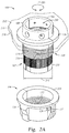
Figure 7 is a side cross-sectional view of the pass-through bulkhead seal fitting 100 similar to the view shown inFigure 6A , with the addition of asealant 700. Thesealant 700 may be a commercially available sealant typically used in the aircraft industry for pass-through fittings. Thesealant 700 may be applied via anozzle 705 to thevolume 630 contained at least partially within themale fitting 102 and thetape 625. Thesealant 700 may be applied as a liquid at a relatively low viscosity and may cure to a solid or near solid after application. - The
sealant 700 may be applied through thenozzle 705 by piercing thetape 625 adjacent to one of the flaredopenings 660 to form anopening 710 that is in fluid communication with thevolume 630. Thesealant 700 should substantially fill thevolume 630 including any spaces within or adjacent to the existingwiring 600. Additionally, thesealant 700 should be provided in theannular channel 650 to form a seal between thesurface 205 of theradially extending flange 136 and thesurface 212 of thebarrier 210. Thesealant 700 flows through the second openings 645 (hidden by thesealant 700 inFigure 7 but shown inFigure 6A ) into theannular channel 650 in order to provide thesealant 700 to theannular channel 650. - To determine that the
volume 630 is suitably filled with thesealant 700, bulges 715 (only one is shown in this view) are formed within the respective volumes 675 (only one is shown in this view). Thebulges 715 may be slight protrusions in thetape 625 that extend radially outward and provide a visual indication of the level ofsealant 700 within thevolume 630. A portion of thefirst openings 640 not used to insert thenozzle 705 may be referred to as sealant exit ports that provide an indication of the sealant level within thevolume 630. Additionally, the level ofsealant 700 within theannular channel 650 may be determined whensealant 700 is within, or exits, thethird openings 680 of theradially extending flange 136. Thethird openings 680 may be referred to as sealant exit ports. Thesealant 700 may then harden after a few hours to provide a seal between at the opening in thebarrier 210, which effectively seals the pressurized environment HP from the lower pressure environment LP. Thesealant 700 that resides in the annular depression 655 (shown inFigures 6A and6B ) may further secure the pass-through bulkhead seal fitting 100 to the bound existingwiring 600 and thus prevent movement therebetween. - The pass-through bulkhead seal fitting 100 as described herein provides easier and quicker installation and removal as compared to conventional fittings. The pass-through bulkhead seal fitting 100 as described herein reduces parts from the conventional fittings (up to nine loose parts) to four parts (the
first portion 106 and thesecond portion 108 of themale fitting 102, and thefirst portion 116 and thesecond portion 118 of the multi-piece nut 104). It is estimated that the install time for the pass-through bulkhead seal fitting 100 is reduced by about 4 minutes as compared to the conventional fitting install time. There are hundreds of these pass-through connections on a typical aircraft and several hours are saved using the pass-through bulkhead seal fitting 100 as described herein. Further, as the pass-through connections are numerous on an aircraft, the reduced part count saves weight. Additionally, the pass-through bulkhead seal fitting 100 requires no specialized tooling as is required on the conventional fittings. - According to another aspect, there is provided a pass-through bulkhead seal fitting, the bulkhead seal fitting comprising: a male fitting comprising a tubular body that is separable to receive existing wiring; and a nut that is separable to receive existing wiring and being rotatable in a single direction relative to a longitudinal axis of the male fitting.
- Optionally, the tubular body comprises two portions.
- Optionally, each of the two portions of the tubular body comprises a plurality of sealant exit ports that extend from an inner surface of the respective portion of the tubular body to an outer surface of the respective portion of the tubular body.
- Optionally, the plurality of sealant exit ports are located at a first end of the respective portions of the tubular body.
- Optionally, each of the two portions of the tubular body includes a second end opposing the first end that includes a plurality of raised features on the outer surface thereof.
- Optionally, the plurality of raised features are oriented along the longitudinal axis of the male fitting.
- Optionally, the tubular body comprises a flange extending in a radial direction from an outer surface thereof.
- Optionally, the flange includes a channel that is in fluid communication with an inner surface of the tubular body.
- Optionally, the flange includes one or more openings for determining a sealant level within the channel.
- Optionally, each of the two portions of the tubular body includes an interlock device securing the tubular body.
- Optionally, the separable nut includes a detent that interfaces with the raised features to prevent the nut from rotating in a direction other than the single direction.
- According to another aspect, there is provided a pass-through bulkhead seal fitting, the bulkhead seal fitting comprising: a male fitting comprising a tubular body and having a plurality of sealant exit ports located in a radial direction relative to a longitudinal axis of the male fitting through an inner surface of the tubular body to an outer surface of the tubular body; and a separable nut portion that is rotatable in a single direction relative to the longitudinal axis of the male fitting.
- Optionally, the tubular body is separable.
- Optionally, the tubular body comprises two portions.
- Optionally, the plurality of sealant exit ports are formed at a first end of the tubular body.
- Optionally, the tubular body includes a second end opposing the first end that includes a plurality of raised features formed in the outer surface thereof.
- Optionally, the separable nut includes a detent that interfaces with the raised features to prevent the separable nut from rotating in a direction other than the single direction.
- According to another aspect, there is provided, a pass-through bulkhead seal fitting, the bulkhead seal fitting comprising: a male fitting comprising a tubular two-piece body; and a separable two-piece nut that is rotatable in a first direction relative to a longitudinal axis of the male fitting and having one or more detents formed thereon that prevents rotation of the nut in a second direction opposite to the first direction.
- Optionally, the male fitting comprises a first end having a plurality of sealant exit ports and a second end opposing the first end.
- Optionally, the second end includes an outer peripheral surface having a plurality of raised features formed thereon that interface with the one or more detents.
- Optionally, each piece of the tubular two-piece body includes an interlock device securing the tubular two-piece body.
- Optionally, each piece of the tubular two-piece body comprises a flange extending in a radial direction from an outer surface thereof and the flange includes a channel that is in fluid communication with an inner surface of the tubular two-piece body.
Claims (11)
- A pass-through bulkhead seal fitting, the bulkhead seal fitting comprising:a male fitting (102) comprising a tubular body (105) that is separable to receive existing wiring; anda nut (104) that is separable to receive existing wiring and being rotatable in a single direction relative to a longitudinal axis (225) of the male fitting (102).
- The fitting of claim 1, wherein the tubular body (105) comprises two portions (106, 108).
- The fitting of claim 2, wherein each of the two portions (106, 108) of the tubular body (105) comprises a plurality of sealant exit ports (640) that extend from an inner surface of the respective portion (106, 108) of the tubular body (105) to an outer surface of the respective portion (106, 108) of the tubular body (105).
- The fitting of claim 3, wherein the plurality of sealant exit ports (640) are located at a first end (610) of the respective portions (106, 108) of the tubular body (105).
- The fitting of claim 4, wherein each of the two portions (106, 108) of the tubular body (105) includes a second end (615) opposing the first end (610) that includes a plurality of raised features (230) on the outer surface thereof.
- The fitting of claim 5, wherein the plurality of raised features (230) are oriented along the longitudinal axis (225) of the male fitting (102).
- The fitting of any one of claims 1 to 6, wherein the tubular body (105) comprises a flange (136) extending in a radial direction from an outer surface thereof.
- The fitting of claim 7, wherein the flange (136) includes a channel (650) that is in fluid communication with an inner surface of the tubular body (105).
- The fitting of claim 8, wherein the flange (136) includes one or more openings (680) for determining a sealant level within the channel (650).
- The fitting of claim 5 or claim 6, or the fitting of any one of claims 7 to 9 when dependent upon claim 5 or claim 6, wherein the nut (104) includes a detent (240) that interfaces with the raised features (230) to prevent the nut (104) from rotating in a direction other than the single direction.
- The fitting of claim 10, wherein each of the two portions (106, 108) of the tubular body (105) includes an interlock device (125) securing the tubular body (105).
Applications Claiming Priority (1)
| Application Number | Priority Date | Filing Date | Title |
|---|---|---|---|
| US14/997,074 US10113669B2 (en) | 2016-01-15 | 2016-01-15 | Pass-through bulkhead seal fitting |
Publications (2)
| Publication Number | Publication Date |
|---|---|
| EP3193419A1 true EP3193419A1 (en) | 2017-07-19 |
| EP3193419B1 EP3193419B1 (en) | 2021-05-05 |
Family
ID=57799587
Family Applications (1)
| Application Number | Title | Priority Date | Filing Date |
|---|---|---|---|
| EP17151335.1A Active EP3193419B1 (en) | 2016-01-15 | 2017-01-13 | Pass-through bulkhead seal fitting |
Country Status (3)
| Country | Link |
|---|---|
| US (2) | US10113669B2 (en) |
| EP (1) | EP3193419B1 (en) |
| JP (1) | JP6872372B2 (en) |
Cited By (1)
| Publication number | Priority date | Publication date | Assignee | Title |
|---|---|---|---|---|
| EP3957842A1 (en) * | 2020-08-19 | 2022-02-23 | Pratt & Whitney Canada Corp. | Aircraft firewall feedthrough device |
Families Citing this family (15)
| Publication number | Priority date | Publication date | Assignee | Title |
|---|---|---|---|---|
| US10113669B2 (en) | 2016-01-15 | 2018-10-30 | The Boeing Company | Pass-through bulkhead seal fitting |
| EP3526867B1 (en) * | 2016-10-17 | 2021-08-25 | Huber+Suhner Ag | Cable gland comprising a slip on grommet |
| US10369589B2 (en) * | 2017-05-12 | 2019-08-06 | Alan Dale | Nozzle adapter |
| FR3076105B1 (en) * | 2017-12-21 | 2020-10-30 | Latelec | HARNESS OUTLET ADAPTER OF A WIRING PATH AND METHOD FOR INSTALLING SUCH ADAPTER |
| JP2020037953A (en) * | 2018-09-03 | 2020-03-12 | パナソニックIpマネジメント株式会社 | Split nut, split bolt, bolt and nut structure using these, and pipe protective method |
| US10851672B2 (en) * | 2018-09-04 | 2020-12-01 | General Electric Company | Grommet for a turbine engine |
| CN109167326B (en) * | 2018-11-06 | 2024-10-18 | 浙江德尔信连接器有限公司 | Double-locking cable joint |
| CN109894816A (en) * | 2019-03-14 | 2019-06-18 | 中山市城裕盛晖五金电热制品有限公司 | Mechanical sealing process and structure for flange and electric heating element of heater |
| US12049915B2 (en) * | 2019-08-12 | 2024-07-30 | Mikeysquickcoupler Llc | Split coupler for pipes |
| DE102020116248A1 (en) | 2020-06-19 | 2021-12-23 | Leoni Kabel Gmbh | Pressure nut for cable or hose connections |
| KR102563816B1 (en) * | 2021-08-18 | 2023-08-09 | 한국원자력연구원 | Laser Cutting Device |
| US12188600B2 (en) * | 2023-03-28 | 2025-01-07 | Advanced Drainage Systems, Inc. | Fasteners for a manifold |
| US12463409B2 (en) * | 2023-06-21 | 2025-11-04 | The Boeing Company | Split ring wire bundle seal sleeve and assembly process |
| US12345168B2 (en) * | 2023-11-27 | 2025-07-01 | Rtx Corporation | Fitting for an instrument lead with a connector for a gas turbine engine |
| US20260098580A1 (en) * | 2024-10-04 | 2026-04-09 | Aptiv Technologies AG | Seal Assembly |
Citations (4)
| Publication number | Priority date | Publication date | Assignee | Title |
|---|---|---|---|---|
| US4431198A (en) * | 1982-11-05 | 1984-02-14 | Amp Incorporated | Device for conduit seal and repair |
| US20030063866A1 (en) * | 2001-09-28 | 2003-04-03 | Melton Stuart R. | Fiber optic receptacle |
| US20060233496A1 (en) * | 2005-04-15 | 2006-10-19 | Khemakhem M Hamed A | Hybrid fiber/copper connector system and method |
| WO2015047508A1 (en) * | 2013-07-16 | 2015-04-02 | 3M Innovative Properties Company | Connector for telecommunication enclosures |
Family Cites Families (43)
| Publication number | Priority date | Publication date | Assignee | Title |
|---|---|---|---|---|
| US625448A (en) * | 1899-05-23 | Quick-repair device for pipes | ||
| US2924467A (en) * | 1953-07-15 | 1960-02-09 | William J Burch | Bulkhead stuffing tube |
| US2784385A (en) * | 1954-02-02 | 1957-03-05 | Harlan M Ennis | Safety electric coupling |
| US3031212A (en) * | 1957-12-06 | 1962-04-24 | Boeing Co | Pipe to wall connection having injection type securing and sealing means |
| US3104120A (en) * | 1958-12-01 | 1963-09-17 | Ahlport Brodie | Coupling for conduits |
| US3224796A (en) * | 1962-08-10 | 1965-12-21 | Harold H Burkitt | Wall bushing for pipes and cables |
| US3448896A (en) * | 1966-02-23 | 1969-06-10 | Sunstar Dentifrice Co Ltd | Dispensing tube assembly |
| US3888454A (en) * | 1973-01-03 | 1975-06-10 | Harsco Corp | Means for forming a seal about a conduit |
| JPS5070489U (en) * | 1973-10-31 | 1975-06-21 | ||
| US4059324A (en) * | 1976-09-15 | 1977-11-22 | The Bendix Corporation | Electrical connector |
| US4268103A (en) * | 1979-02-02 | 1981-05-19 | The Bendix Corporation | Electrical connector assembly having anti-decoupling mechanism |
| US4359254A (en) * | 1980-11-14 | 1982-11-16 | The Bendix Corporation | Electrical connector coupling ring having an integral spring |
| US4462652A (en) * | 1981-08-03 | 1984-07-31 | The Bendix Corporation | Coupling nut for an electrical connector |
| US4500154A (en) * | 1983-03-30 | 1985-02-19 | Allied Corporation | Electrical connector assembly having an anti-decoupling device |
| US4487470A (en) * | 1983-05-11 | 1984-12-11 | The Bendix Corporation | Anti-decoupling mechanism for an electrical connector assembly |
| US4749251A (en) * | 1985-07-11 | 1988-06-07 | Hughes Aircraft Company | Connector locking system |
| JPS6281417U (en) * | 1985-11-06 | 1987-05-25 | ||
| US4639064A (en) * | 1986-02-28 | 1987-01-27 | Allied Corporation | Anti-decoupling resisting and EMI shielding means for an electrical connector assembly |
| DE4004564A1 (en) * | 1990-02-14 | 1991-08-29 | Kirchner Fraenk Rohr | PIPE CONNECTING PART, PIPE CONNECTING PART, AND RELATED NUT |
| US5406032A (en) * | 1992-02-13 | 1995-04-11 | The Boeing Company | Apparatus and method for supporting wire bundles within a structure |
| DE4322032C1 (en) * | 1993-07-02 | 1994-06-30 | Pflitsch Gmbh & Co Kg | Device for the sealed laying of pipes, lines and the like |
| US5739468A (en) * | 1996-08-26 | 1998-04-14 | Mcdonnell Douglas Corporation | Cable hanger |
| DE19828838B4 (en) * | 1998-06-27 | 2006-10-12 | Obo Bettermann Gmbh & Co. Kg | Device for the sealed installation of pipes, cables, lines or the like long molded parts by device walls |
| AR019741A1 (en) * | 1998-07-15 | 2002-03-13 | Rxs Schrumpftech Garnituren | SHUTTER BODY FOR CABLE GUARDNITIONS |
| US6443497B1 (en) * | 2000-08-03 | 2002-09-03 | David B. Gravison | Device and method for tightening a spout |
| US6619697B2 (en) * | 2000-12-27 | 2003-09-16 | Nkf Kabel B.V. | Y-branch splittable connector |
| FR2825199B1 (en) * | 2001-05-23 | 2004-02-20 | Nexans | APPARATUS BOX, ESPECIALLY SPLICE BOX |
| US7063132B2 (en) * | 2003-12-29 | 2006-06-20 | Bradford White Corporation | Multi-wall heat exchanger for a water heater |
| US7132605B2 (en) * | 2005-04-01 | 2006-11-07 | Adc Telecommunications, Inc. | Split cable seal |
| FR2892568B1 (en) * | 2005-10-20 | 2008-09-26 | Souriau Sa | CONNECTION FOR CONTACT ELEMENT |
| AR059443A1 (en) * | 2006-02-15 | 2008-04-09 | Tyco Electronics Brasil Ltda | ENERGY DISTRIBUTION SYSTEM |
| US20080246276A1 (en) * | 2006-05-22 | 2008-10-09 | Bravo Sergio M | Sump Wall Penetration Fitting |
| US9106012B2 (en) * | 2008-05-30 | 2015-08-11 | Itt Manufacturing Enterprises, Inc. | Antirotation coupling for connector |
| US8146951B2 (en) * | 2009-05-21 | 2012-04-03 | Marine Town Inc. | Scupper joint for ship |
| CA2804727C (en) * | 2010-07-17 | 2015-11-17 | Harting Electric Gmbh & Co. Kg | Helical cable tension relief |
| CN102418811B (en) * | 2010-09-28 | 2014-12-10 | 中国商用飞机有限责任公司 | Sealed wall penetrating piece |
| DE102011001079A1 (en) * | 2011-03-03 | 2012-09-06 | Phoenix Contact Gmbh & Co. Kg | Connection system of a housing of a connector with a nut |
| DE102012007460A1 (en) * | 2012-04-13 | 2013-10-17 | Pflitsch Gmbh & Co. Kg | Device for laying long molded parts through device walls |
| JP5092062B1 (en) * | 2012-04-26 | 2012-12-05 | オーム電機株式会社 | cable clamp |
| US9174159B2 (en) | 2013-08-16 | 2015-11-03 | 3M Innovative Properties Company | Framed pleated air filter with upstream bridging filaments |
| US9906007B2 (en) * | 2014-12-18 | 2018-02-27 | The Boeing Company | Grommets for supporting harnesses and systems and methods including the same |
| DE202016002240U1 (en) * | 2015-04-09 | 2016-06-24 | Franz Blanke | Bulkhead connection for a fluid-carrying pipe to create a passage through a bulkhead wall |
| US10113669B2 (en) | 2016-01-15 | 2018-10-30 | The Boeing Company | Pass-through bulkhead seal fitting |
-
2016
- 2016-01-15 US US14/997,074 patent/US10113669B2/en active Active
-
2017
- 2017-01-13 JP JP2017004429A patent/JP6872372B2/en active Active
- 2017-01-13 EP EP17151335.1A patent/EP3193419B1/en active Active
-
2018
- 2018-10-26 US US16/172,471 patent/US11162616B2/en active Active
Patent Citations (4)
| Publication number | Priority date | Publication date | Assignee | Title |
|---|---|---|---|---|
| US4431198A (en) * | 1982-11-05 | 1984-02-14 | Amp Incorporated | Device for conduit seal and repair |
| US20030063866A1 (en) * | 2001-09-28 | 2003-04-03 | Melton Stuart R. | Fiber optic receptacle |
| US20060233496A1 (en) * | 2005-04-15 | 2006-10-19 | Khemakhem M Hamed A | Hybrid fiber/copper connector system and method |
| WO2015047508A1 (en) * | 2013-07-16 | 2015-04-02 | 3M Innovative Properties Company | Connector for telecommunication enclosures |
Cited By (1)
| Publication number | Priority date | Publication date | Assignee | Title |
|---|---|---|---|---|
| EP3957842A1 (en) * | 2020-08-19 | 2022-02-23 | Pratt & Whitney Canada Corp. | Aircraft firewall feedthrough device |
Also Published As
| Publication number | Publication date |
|---|---|
| JP2017163821A (en) | 2017-09-14 |
| US10113669B2 (en) | 2018-10-30 |
| US20190063640A1 (en) | 2019-02-28 |
| JP6872372B2 (en) | 2021-05-19 |
| US11162616B2 (en) | 2021-11-02 |
| EP3193419B1 (en) | 2021-05-05 |
| US20170205001A1 (en) | 2017-07-20 |
Similar Documents
| Publication | Publication Date | Title |
|---|---|---|
| US11162616B2 (en) | Pass-through bulkhead seal fitting | |
| US4089549A (en) | Simultaneous plural fluid conductor connections | |
| US11193609B2 (en) | Pipe coupling | |
| US9784389B2 (en) | Pipe joint | |
| CN103748369A (en) | Reusable press-in retainer | |
| US9822912B2 (en) | Push-to-connect fitting device, arrangement and method | |
| AU2018200718B2 (en) | System and apparatus for conduit squeeze retainer | |
| US10704975B2 (en) | Visual torque indication for threaded joints | |
| KR100264085B1 (en) | High pressure quick connector for automobile brake system and its manufacturing method | |
| US20140265312A1 (en) | Apparatuses and methods for providing finger-tightened and ratchet-secured connections between conduits | |
| CA2720485A1 (en) | Mechanical pipe fitting device assembly | |
| US10995891B2 (en) | Connector assemblies for connecting tubulars and related methods | |
| US20200332933A1 (en) | Mechanical joint restraint | |
| GB2514556A (en) | Locking device | |
| CA2007158A1 (en) | Safety connection into passages in a tubular body | |
| WO2016146216A1 (en) | Device for equalising an internal pressure in a closed housing | |
| USRE48436E1 (en) | Dual duct flexible coupling apparatus and methods of use | |
| DE102010018954B4 (en) | Device for plug-in connection of a first line section with a second line section of a fluid line | |
| US20160319854A1 (en) | Method and Apparatus for Limiting Compression Between Flanges of a Sealed Structure | |
| EP2191184A1 (en) | Rotomold bead | |
| US7908730B2 (en) | PTC fitting cartridge | |
| US20110116887A1 (en) | Aligned and axially loaded pig injector valve, threaded connection and method for connecting threaded members | |
| AU2021261896A1 (en) | Compression fitting with visual torque indicator | |
| US12474536B2 (en) | Multi-port gland for an optical closure | |
| US20250264175A1 (en) | Lock out tag out for quick disconnect |
Legal Events
| Date | Code | Title | Description |
|---|---|---|---|
| PUAI | Public reference made under article 153(3) epc to a published international application that has entered the european phase |
Free format text: ORIGINAL CODE: 0009012 |
|
| STAA | Information on the status of an ep patent application or granted ep patent |
Free format text: STATUS: REQUEST FOR EXAMINATION WAS MADE |
|
| 17P | Request for examination filed |
Effective date: 20170113 |
|
| AK | Designated contracting states |
Kind code of ref document: A1 Designated state(s): AL AT BE BG CH CY CZ DE DK EE ES FI FR GB GR HR HU IE IS IT LI LT LU LV MC MK MT NL NO PL PT RO RS SE SI SK SM TR |
|
| AX | Request for extension of the european patent |
Extension state: BA ME |
|
| STAA | Information on the status of an ep patent application or granted ep patent |
Free format text: STATUS: EXAMINATION IS IN PROGRESS |
|
| 17Q | First examination report despatched |
Effective date: 20180212 |
|
| GRAP | Despatch of communication of intention to grant a patent |
Free format text: ORIGINAL CODE: EPIDOSNIGR1 |
|
| STAA | Information on the status of an ep patent application or granted ep patent |
Free format text: STATUS: GRANT OF PATENT IS INTENDED |
|
| INTG | Intention to grant announced |
Effective date: 20200810 |
|
| GRAJ | Information related to disapproval of communication of intention to grant by the applicant or resumption of examination proceedings by the epo deleted |
Free format text: ORIGINAL CODE: EPIDOSDIGR1 |
|
| STAA | Information on the status of an ep patent application or granted ep patent |
Free format text: STATUS: EXAMINATION IS IN PROGRESS |
|
| GRAP | Despatch of communication of intention to grant a patent |
Free format text: ORIGINAL CODE: EPIDOSNIGR1 |
|
| STAA | Information on the status of an ep patent application or granted ep patent |
Free format text: STATUS: GRANT OF PATENT IS INTENDED |
|
| INTC | Intention to grant announced (deleted) | ||
| INTG | Intention to grant announced |
Effective date: 20201221 |
|
| GRAS | Grant fee paid |
Free format text: ORIGINAL CODE: EPIDOSNIGR3 |
|
| GRAA | (expected) grant |
Free format text: ORIGINAL CODE: 0009210 |
|
| STAA | Information on the status of an ep patent application or granted ep patent |
Free format text: STATUS: THE PATENT HAS BEEN GRANTED |
|
| AK | Designated contracting states |
Kind code of ref document: B1 Designated state(s): AL AT BE BG CH CY CZ DE DK EE ES FI FR GB GR HR HU IE IS IT LI LT LU LV MC MK MT NL NO PL PT RO RS SE SI SK SM TR |
|
| REG | Reference to a national code |
Ref country code: GB Ref legal event code: FG4D |
|
| REG | Reference to a national code |
Ref country code: CH Ref legal event code: EP |
|
| REG | Reference to a national code |
Ref country code: AT Ref legal event code: REF Ref document number: 1391018 Country of ref document: AT Kind code of ref document: T Effective date: 20210515 |
|
| REG | Reference to a national code |
Ref country code: DE Ref legal event code: R096 Ref document number: 602017037890 Country of ref document: DE |
|
| REG | Reference to a national code |
Ref country code: IE Ref legal event code: FG4D |
|
| REG | Reference to a national code |
Ref country code: LT Ref legal event code: MG9D |
|
| REG | Reference to a national code |
Ref country code: AT Ref legal event code: MK05 Ref document number: 1391018 Country of ref document: AT Kind code of ref document: T Effective date: 20210505 |
|
| PG25 | Lapsed in a contracting state [announced via postgrant information from national office to epo] |
Ref country code: AT Free format text: LAPSE BECAUSE OF FAILURE TO SUBMIT A TRANSLATION OF THE DESCRIPTION OR TO PAY THE FEE WITHIN THE PRESCRIBED TIME-LIMIT Effective date: 20210505 Ref country code: BG Free format text: LAPSE BECAUSE OF FAILURE TO SUBMIT A TRANSLATION OF THE DESCRIPTION OR TO PAY THE FEE WITHIN THE PRESCRIBED TIME-LIMIT Effective date: 20210805 Ref country code: HR Free format text: LAPSE BECAUSE OF FAILURE TO SUBMIT A TRANSLATION OF THE DESCRIPTION OR TO PAY THE FEE WITHIN THE PRESCRIBED TIME-LIMIT Effective date: 20210505 Ref country code: LT Free format text: LAPSE BECAUSE OF FAILURE TO SUBMIT A TRANSLATION OF THE DESCRIPTION OR TO PAY THE FEE WITHIN THE PRESCRIBED TIME-LIMIT Effective date: 20210505 Ref country code: FI Free format text: LAPSE BECAUSE OF FAILURE TO SUBMIT A TRANSLATION OF THE DESCRIPTION OR TO PAY THE FEE WITHIN THE PRESCRIBED TIME-LIMIT Effective date: 20210505 |
|
| PG25 | Lapsed in a contracting state [announced via postgrant information from national office to epo] |
Ref country code: IS Free format text: LAPSE BECAUSE OF FAILURE TO SUBMIT A TRANSLATION OF THE DESCRIPTION OR TO PAY THE FEE WITHIN THE PRESCRIBED TIME-LIMIT Effective date: 20210905 Ref country code: GR Free format text: LAPSE BECAUSE OF FAILURE TO SUBMIT A TRANSLATION OF THE DESCRIPTION OR TO PAY THE FEE WITHIN THE PRESCRIBED TIME-LIMIT Effective date: 20210806 Ref country code: LV Free format text: LAPSE BECAUSE OF FAILURE TO SUBMIT A TRANSLATION OF THE DESCRIPTION OR TO PAY THE FEE WITHIN THE PRESCRIBED TIME-LIMIT Effective date: 20210505 Ref country code: SE Free format text: LAPSE BECAUSE OF FAILURE TO SUBMIT A TRANSLATION OF THE DESCRIPTION OR TO PAY THE FEE WITHIN THE PRESCRIBED TIME-LIMIT Effective date: 20210505 Ref country code: RS Free format text: LAPSE BECAUSE OF FAILURE TO SUBMIT A TRANSLATION OF THE DESCRIPTION OR TO PAY THE FEE WITHIN THE PRESCRIBED TIME-LIMIT Effective date: 20210505 Ref country code: PL Free format text: LAPSE BECAUSE OF FAILURE TO SUBMIT A TRANSLATION OF THE DESCRIPTION OR TO PAY THE FEE WITHIN THE PRESCRIBED TIME-LIMIT Effective date: 20210505 Ref country code: PT Free format text: LAPSE BECAUSE OF FAILURE TO SUBMIT A TRANSLATION OF THE DESCRIPTION OR TO PAY THE FEE WITHIN THE PRESCRIBED TIME-LIMIT Effective date: 20210906 Ref country code: NO Free format text: LAPSE BECAUSE OF FAILURE TO SUBMIT A TRANSLATION OF THE DESCRIPTION OR TO PAY THE FEE WITHIN THE PRESCRIBED TIME-LIMIT Effective date: 20210805 |
|
| REG | Reference to a national code |
Ref country code: NL Ref legal event code: MP Effective date: 20210505 |
|
| PG25 | Lapsed in a contracting state [announced via postgrant information from national office to epo] |
Ref country code: NL Free format text: LAPSE BECAUSE OF FAILURE TO SUBMIT A TRANSLATION OF THE DESCRIPTION OR TO PAY THE FEE WITHIN THE PRESCRIBED TIME-LIMIT Effective date: 20210505 |
|
| PG25 | Lapsed in a contracting state [announced via postgrant information from national office to epo] |
Ref country code: SM Free format text: LAPSE BECAUSE OF FAILURE TO SUBMIT A TRANSLATION OF THE DESCRIPTION OR TO PAY THE FEE WITHIN THE PRESCRIBED TIME-LIMIT Effective date: 20210505 Ref country code: SK Free format text: LAPSE BECAUSE OF FAILURE TO SUBMIT A TRANSLATION OF THE DESCRIPTION OR TO PAY THE FEE WITHIN THE PRESCRIBED TIME-LIMIT Effective date: 20210505 Ref country code: DK Free format text: LAPSE BECAUSE OF FAILURE TO SUBMIT A TRANSLATION OF THE DESCRIPTION OR TO PAY THE FEE WITHIN THE PRESCRIBED TIME-LIMIT Effective date: 20210505 Ref country code: EE Free format text: LAPSE BECAUSE OF FAILURE TO SUBMIT A TRANSLATION OF THE DESCRIPTION OR TO PAY THE FEE WITHIN THE PRESCRIBED TIME-LIMIT Effective date: 20210505 Ref country code: CZ Free format text: LAPSE BECAUSE OF FAILURE TO SUBMIT A TRANSLATION OF THE DESCRIPTION OR TO PAY THE FEE WITHIN THE PRESCRIBED TIME-LIMIT Effective date: 20210505 Ref country code: RO Free format text: LAPSE BECAUSE OF FAILURE TO SUBMIT A TRANSLATION OF THE DESCRIPTION OR TO PAY THE FEE WITHIN THE PRESCRIBED TIME-LIMIT Effective date: 20210505 Ref country code: ES Free format text: LAPSE BECAUSE OF FAILURE TO SUBMIT A TRANSLATION OF THE DESCRIPTION OR TO PAY THE FEE WITHIN THE PRESCRIBED TIME-LIMIT Effective date: 20210505 |
|
| REG | Reference to a national code |
Ref country code: DE Ref legal event code: R097 Ref document number: 602017037890 Country of ref document: DE |
|
| PLBE | No opposition filed within time limit |
Free format text: ORIGINAL CODE: 0009261 |
|
| STAA | Information on the status of an ep patent application or granted ep patent |
Free format text: STATUS: NO OPPOSITION FILED WITHIN TIME LIMIT |
|
| 26N | No opposition filed |
Effective date: 20220208 |
|
| PG25 | Lapsed in a contracting state [announced via postgrant information from national office to epo] |
Ref country code: IS Free format text: LAPSE BECAUSE OF FAILURE TO SUBMIT A TRANSLATION OF THE DESCRIPTION OR TO PAY THE FEE WITHIN THE PRESCRIBED TIME-LIMIT Effective date: 20210905 Ref country code: AL Free format text: LAPSE BECAUSE OF FAILURE TO SUBMIT A TRANSLATION OF THE DESCRIPTION OR TO PAY THE FEE WITHIN THE PRESCRIBED TIME-LIMIT Effective date: 20210505 |
|
| PG25 | Lapsed in a contracting state [announced via postgrant information from national office to epo] |
Ref country code: IT Free format text: LAPSE BECAUSE OF FAILURE TO SUBMIT A TRANSLATION OF THE DESCRIPTION OR TO PAY THE FEE WITHIN THE PRESCRIBED TIME-LIMIT Effective date: 20210505 |
|
| PG25 | Lapsed in a contracting state [announced via postgrant information from national office to epo] |
Ref country code: MC Free format text: LAPSE BECAUSE OF FAILURE TO SUBMIT A TRANSLATION OF THE DESCRIPTION OR TO PAY THE FEE WITHIN THE PRESCRIBED TIME-LIMIT Effective date: 20210505 |
|
| REG | Reference to a national code |
Ref country code: CH Ref legal event code: PL |
|
| GBPC | Gb: european patent ceased through non-payment of renewal fee |
Effective date: 20220113 |
|
| REG | Reference to a national code |
Ref country code: BE Ref legal event code: MM Effective date: 20220131 |
|
| PG25 | Lapsed in a contracting state [announced via postgrant information from national office to epo] |
Ref country code: LU Free format text: LAPSE BECAUSE OF NON-PAYMENT OF DUE FEES Effective date: 20220113 Ref country code: GB Free format text: LAPSE BECAUSE OF NON-PAYMENT OF DUE FEES Effective date: 20220113 |
|
| PG25 | Lapsed in a contracting state [announced via postgrant information from national office to epo] |
Ref country code: BE Free format text: LAPSE BECAUSE OF NON-PAYMENT OF DUE FEES Effective date: 20220131 |
|
| PG25 | Lapsed in a contracting state [announced via postgrant information from national office to epo] |
Ref country code: LI Free format text: LAPSE BECAUSE OF NON-PAYMENT OF DUE FEES Effective date: 20220131 Ref country code: CH Free format text: LAPSE BECAUSE OF NON-PAYMENT OF DUE FEES Effective date: 20220131 |
|
| PG25 | Lapsed in a contracting state [announced via postgrant information from national office to epo] |
Ref country code: IE Free format text: LAPSE BECAUSE OF NON-PAYMENT OF DUE FEES Effective date: 20220113 |
|
| P01 | Opt-out of the competence of the unified patent court (upc) registered |
Effective date: 20230516 |
|
| PG25 | Lapsed in a contracting state [announced via postgrant information from national office to epo] |
Ref country code: HU Free format text: LAPSE BECAUSE OF FAILURE TO SUBMIT A TRANSLATION OF THE DESCRIPTION OR TO PAY THE FEE WITHIN THE PRESCRIBED TIME-LIMIT; INVALID AB INITIO Effective date: 20170113 |
|
| PG25 | Lapsed in a contracting state [announced via postgrant information from national office to epo] |
Ref country code: MK Free format text: LAPSE BECAUSE OF FAILURE TO SUBMIT A TRANSLATION OF THE DESCRIPTION OR TO PAY THE FEE WITHIN THE PRESCRIBED TIME-LIMIT Effective date: 20210505 Ref country code: CY Free format text: LAPSE BECAUSE OF FAILURE TO SUBMIT A TRANSLATION OF THE DESCRIPTION OR TO PAY THE FEE WITHIN THE PRESCRIBED TIME-LIMIT Effective date: 20210505 |
|
| PG25 | Lapsed in a contracting state [announced via postgrant information from national office to epo] |
Ref country code: MT Free format text: LAPSE BECAUSE OF FAILURE TO SUBMIT A TRANSLATION OF THE DESCRIPTION OR TO PAY THE FEE WITHIN THE PRESCRIBED TIME-LIMIT Effective date: 20210505 |
|
| PG25 | Lapsed in a contracting state [announced via postgrant information from national office to epo] |
Ref country code: TR Free format text: LAPSE BECAUSE OF FAILURE TO SUBMIT A TRANSLATION OF THE DESCRIPTION OR TO PAY THE FEE WITHIN THE PRESCRIBED TIME-LIMIT Effective date: 20210505 |
|
| PGFP | Annual fee paid to national office [announced via postgrant information from national office to epo] |
Ref country code: DE Payment date: 20260128 Year of fee payment: 10 |
|
| PGFP | Annual fee paid to national office [announced via postgrant information from national office to epo] |
Ref country code: FR Payment date: 20260126 Year of fee payment: 10 |