EP3193386A1 - Secondary battery - Google Patents
Secondary battery Download PDFInfo
- Publication number
- EP3193386A1 EP3193386A1 EP17150790.8A EP17150790A EP3193386A1 EP 3193386 A1 EP3193386 A1 EP 3193386A1 EP 17150790 A EP17150790 A EP 17150790A EP 3193386 A1 EP3193386 A1 EP 3193386A1
- Authority
- EP
- European Patent Office
- Prior art keywords
- connecting piece
- tab
- cap plate
- secondary battery
- cell
- Prior art date
- Legal status (The legal status is an assumption and is not a legal conclusion. Google has not performed a legal analysis and makes no representation as to the accuracy of the status listed.)
- Granted
Links
Images



Classifications
-
- H—ELECTRICITY
- H01—ELECTRIC ELEMENTS
- H01M—PROCESSES OR MEANS, e.g. BATTERIES, FOR THE DIRECT CONVERSION OF CHEMICAL ENERGY INTO ELECTRICAL ENERGY
- H01M50/00—Constructional details or processes of manufacture of the non-active parts of electrochemical cells other than fuel cells, e.g. hybrid cells
- H01M50/50—Current conducting connections for cells or batteries
- H01M50/528—Fixed electrical connections, i.e. not intended for disconnection
- H01M50/529—Intercell connections through partitions, e.g. in a battery casing
-
- H—ELECTRICITY
- H01—ELECTRIC ELEMENTS
- H01M—PROCESSES OR MEANS, e.g. BATTERIES, FOR THE DIRECT CONVERSION OF CHEMICAL ENERGY INTO ELECTRICAL ENERGY
- H01M10/00—Secondary cells; Manufacture thereof
- H01M10/04—Construction or manufacture in general
-
- H—ELECTRICITY
- H01—ELECTRIC ELEMENTS
- H01M—PROCESSES OR MEANS, e.g. BATTERIES, FOR THE DIRECT CONVERSION OF CHEMICAL ENERGY INTO ELECTRICAL ENERGY
- H01M50/00—Constructional details or processes of manufacture of the non-active parts of electrochemical cells other than fuel cells, e.g. hybrid cells
- H01M50/10—Primary casings; Jackets or wrappings
- H01M50/147—Lids or covers
- H01M50/148—Lids or covers characterised by their shape
- H01M50/15—Lids or covers characterised by their shape for prismatic or rectangular cells
-
- H—ELECTRICITY
- H01—ELECTRIC ELEMENTS
- H01M—PROCESSES OR MEANS, e.g. BATTERIES, FOR THE DIRECT CONVERSION OF CHEMICAL ENERGY INTO ELECTRICAL ENERGY
- H01M50/00—Constructional details or processes of manufacture of the non-active parts of electrochemical cells other than fuel cells, e.g. hybrid cells
- H01M50/50—Current conducting connections for cells or batteries
- H01M50/531—Electrode connections inside a battery casing
- H01M50/533—Electrode connections inside a battery casing characterised by the shape of the leads or tabs
-
- H—ELECTRICITY
- H01—ELECTRIC ELEMENTS
- H01M—PROCESSES OR MEANS, e.g. BATTERIES, FOR THE DIRECT CONVERSION OF CHEMICAL ENERGY INTO ELECTRICAL ENERGY
- H01M50/00—Constructional details or processes of manufacture of the non-active parts of electrochemical cells other than fuel cells, e.g. hybrid cells
- H01M50/50—Current conducting connections for cells or batteries
- H01M50/543—Terminals
- H01M50/547—Terminals characterised by the disposition of the terminals on the cells
- H01M50/55—Terminals characterised by the disposition of the terminals on the cells on the same side of the cell
-
- H—ELECTRICITY
- H01—ELECTRIC ELEMENTS
- H01M—PROCESSES OR MEANS, e.g. BATTERIES, FOR THE DIRECT CONVERSION OF CHEMICAL ENERGY INTO ELECTRICAL ENERGY
- H01M50/00—Constructional details or processes of manufacture of the non-active parts of electrochemical cells other than fuel cells, e.g. hybrid cells
- H01M50/50—Current conducting connections for cells or batteries
- H01M50/543—Terminals
- H01M50/552—Terminals characterised by their shape
- H01M50/553—Terminals adapted for prismatic, pouch or rectangular cells
-
- H—ELECTRICITY
- H01—ELECTRIC ELEMENTS
- H01M—PROCESSES OR MEANS, e.g. BATTERIES, FOR THE DIRECT CONVERSION OF CHEMICAL ENERGY INTO ELECTRICAL ENERGY
- H01M50/00—Constructional details or processes of manufacture of the non-active parts of electrochemical cells other than fuel cells, e.g. hybrid cells
- H01M50/50—Current conducting connections for cells or batteries
- H01M50/543—Terminals
- H01M50/564—Terminals characterised by their manufacturing process
- H01M50/566—Terminals characterised by their manufacturing process by welding, soldering or brazing
-
- H—ELECTRICITY
- H01—ELECTRIC ELEMENTS
- H01M—PROCESSES OR MEANS, e.g. BATTERIES, FOR THE DIRECT CONVERSION OF CHEMICAL ENERGY INTO ELECTRICAL ENERGY
- H01M10/00—Secondary cells; Manufacture thereof
- H01M10/04—Construction or manufacture in general
- H01M10/0436—Small-sized flat cells or batteries for portable equipment
-
- Y—GENERAL TAGGING OF NEW TECHNOLOGICAL DEVELOPMENTS; GENERAL TAGGING OF CROSS-SECTIONAL TECHNOLOGIES SPANNING OVER SEVERAL SECTIONS OF THE IPC; TECHNICAL SUBJECTS COVERED BY FORMER USPC CROSS-REFERENCE ART COLLECTIONS [XRACs] AND DIGESTS
- Y02—TECHNOLOGIES OR APPLICATIONS FOR MITIGATION OR ADAPTATION AGAINST CLIMATE CHANGE
- Y02E—REDUCTION OF GREENHOUSE GAS [GHG] EMISSIONS, RELATED TO ENERGY GENERATION, TRANSMISSION OR DISTRIBUTION
- Y02E60/00—Enabling technologies; Technologies with a potential or indirect contribution to GHG emissions mitigation
- Y02E60/10—Energy storage using batteries
-
- Y—GENERAL TAGGING OF NEW TECHNOLOGICAL DEVELOPMENTS; GENERAL TAGGING OF CROSS-SECTIONAL TECHNOLOGIES SPANNING OVER SEVERAL SECTIONS OF THE IPC; TECHNICAL SUBJECTS COVERED BY FORMER USPC CROSS-REFERENCE ART COLLECTIONS [XRACs] AND DIGESTS
- Y02—TECHNOLOGIES OR APPLICATIONS FOR MITIGATION OR ADAPTATION AGAINST CLIMATE CHANGE
- Y02P—CLIMATE CHANGE MITIGATION TECHNOLOGIES IN THE PRODUCTION OR PROCESSING OF GOODS
- Y02P70/00—Climate change mitigation technologies in the production process for final industrial or consumer products
- Y02P70/50—Manufacturing or production processes characterised by the final manufactured product
Definitions
- the present invention relates to a field of battery, and particularly relates to a secondary battery.
- FIGs. 12-14 are schematic assembled views of a secondary battery of the prior art, in which, FIG. 12 is a schematic view illustrating a connection relationship between tabs and electrode terminals before the tabs are bent in the secondary battery of the prior art; FIG. 13 is a perspective view of the secondary battery of the prior art; FIG. 14 is an enlarged view of a circle part of FIG. 13 .
- each connecting piece 3 is welded to one tab 22, the other end of each connecting piece 3 is welded to one electrode terminal 11, and after each connecting piece 3 is welded to the tab 22 and the electrode terminal 11, there is a process of bending the tab, the tab 22 need be bent 180 degrees (that is, the tab 22 is bent twice to form a horizontal U-shape, as shown in FIG.
- each connecting piece 3 is also bent 180 degrees (to similarly form a horizontal U-shape), so that one of the connecting piece 3 and the tab 22 covers and clamps the other of the connecting piece 3 and the tab 22 relative to each other at a position where the connecting piece 3 and the tab 22 are welded together, therefore it has a high requirement on bending property of the connecting piece 3 and bending property of the tab 22. Because the connecting piece 3 easily generates fatigue crack and even fractures at bent positions, thereby affecting the life of the connecting piece 3.
- an object of the present invention is to provide a secondary battery which reduces the requirement on bending property of a connecting piece and greatly reduces chips generated by the connecting piece due to bending fatigue of the connecting piece and a risk that the connecting piece fractures due to bending fatigue of the connecting piece.
- Another object of the present invention is to provide a secondary battery which reduces the requirement on bending property of a tab and greatly reduces a risk that the tab fractures due to bending fatigue of the tab.
- Still another object of the present invention is to provide a secondary battery which can reduce the production cost, improve the production efficiency and increase an available space in the secondary battery from whole height.
- the present invention provides a secondary battery which comprises a cap plate and at least one cell.
- the cap plate is provided with electrode terminals; each cell comprises a main body and tabs electrically connected to the main body and extending from the main body.
- the secondary battery further comprises connecting pieces, each connecting piece is parallel to the cap plate and positioned at an inside of the cap plate in a thickness direction of the cap plate, a longitudinal direction of each connecting piece is parallel to a length direction of the cap plate, a transverse direction of each connecting piece is parallel to a width direction of the cap plate.
- Each connecting piece has: a tab welding portion for being welded to the corresponding tab of each cell; and an electrode terminal welding portion connected to the tab welding portion along the longitudinal direction of each connecting piece for being welded to the corresponding electrode terminal of the cap plate so as to electrically connect the corresponding electrode terminal and the corresponding tab of each cell.
- the present invention has the following beneficial effects: in the secondary battery according to the present invention, the corresponding tab of each cell is welded to the tab welding portion of the corresponding connecting piece, the corresponding electrode terminal of the cap plate is welded to the electrode terminal welding portion of the corresponding connecting piece so as to realize an electrical connection between the corresponding electrode terminal and the corresponding tab of each cell. And during the electrical connection of the connecting piece, each connecting piece need not be bent, which completely eliminates the requirement on bending property of each connecting piece, and in turn eliminates chips generated by each connecting piece due to bending fatigue of each connecting piece and a risk that each connecting piece fractures due to bending fatigue of each connecting piece. Moreover, with such a structure of each connecting piece, the secondary battery of the present invention also increases an available space in the secondary battery from whole height, improves the production efficiency and reduces the production cost.
- a secondary battery according to the present invention comprises a cap plate 1 and at least one cell 2, the cap plate 1 is provided with electrode terminals 11, each cell 2 comprises a main body 21 and tabs 22 electrically connected to the main body 21 and extending from the main body 21.
- the secondary battery further comprises connecting pieces 3. Each connecting piece 3 is parallel to the cap plate 1 and is positioned at an inside of the cap plate 1 in a thickness direction T of the cap plate 1 (in FIG. 5 , the inside is a side out of the paper surface; in FIGs.
- each connecting piece 3 has: a tab welding portion 31 for being welded to the corresponding tab 22 of each cell 2; and an electrode terminal welding portion 32 connected to the tab welding portion 31 along the longitudinal direction L' of each connecting piece 3 for being welded to the corresponding electrode terminal 11 of the cap plate 1 so as to electrically connect the corresponding electrode terminal 11 and the corresponding tab 22 of each cell 2.
- the corresponding tab 22 of each cell 2 is welded to the tab welding portion 31 of the corresponding connecting piece 3
- the corresponding electrode terminal 11 of the cap plate 1 is welded to the electrode terminal welding portion 32 of the corresponding connecting piece 3 so as to realize an electrical connection between the corresponding electrode terminal 11 and the corresponding tab 22 of each cell 2.
- each connecting piece 3 need not be bent, which completely eliminates the requirement on bending property of each connecting piece 3, and in turn eliminates chips generated by each connecting piece 3 due to bending fatigue of each connecting piece 3 and a risk that each connecting piece 3 fractures due to bending fatigue of each connecting piece 3.
- the secondary battery of the present invention also increases an available space in the secondary battery from whole height, improves the production efficiency and reduces the production cost.
- a thickness direction T' of each connecting piece 3 is parallel to the thickness direction T of the cap plate 1.
- the tabs 22 of each cell 2 extend straight from the main body 21 parallel to the main body 21 of each cell 2 and parallel to the width direction W of the cap plate 1.
- the number of the cells 2 is two (i.e.
- the secondary battery comprises the two cells
- the two main bodies 21 of the two cells 2 are parallel to the width direction W of the cap plate 1 and are positioned respectively at two sides of each connecting piece 3 in the transverse direction W' which is parallel to the width direction W of the cap plate 1
- one tab 22 of one cell 2 and one tab 22 of the other cell 2 are electrically connected to the tab welding portion 31 of one corresponding connecting piece 3 along the width direction W of the cap plate 1.
- the number of the cells 2 is not limited to this, and the number of the cells 2 may also be more than two.
- the cells 2 are positioned respectively at the two sides of each connecting piece 3 in the transverse direction W' which is parallel to the width direction W of the cap plate 1, and the number of the cells 2 and a thickness of each cell 2 at one side may be different from the number of the cells 2 and a thickness of each cell 2 at the other side, as long as it assures a total height of the stacked cell(s) 2 at one side is the same as a total height of the stacked cell(s) 2 at the other side.
- the two cells 2 are symmetric about a longitudinal central axis C of each connecting piece 3, the longitudinal central axis C of each connecting piece 3 is parallel to the length direction L of the cap plate 1.
- each tab 22 of each cell 2 has: a planar portion 221 parallel to the width direction W of the cap plate 1 and weld to the tab welding portion 31; and an upright portion 222 extending parallel to the main body 21 and connected to the planar portion 221 so as to form a reversed L shape together with the planar portion 221.
- each tab 22 is bent only once, so that it reduces the requirement on the bending property of each tab 22, and greatly reduces a risk that each tab 22 fractures due to bending fatigue of each tab 22, reduces the production cost, improves the production efficiency and at the same time can increase an available space in the whole secondary battery from whole height.
- each tab 22 in FIG. 9 seems similar to that shown in FIG. 13 , however, each tab 22 in FIG.13 will be bent twice to form a horizontal U shape, each tab 22 in the present invention is bent only once to form a reversed L shape due to a relative position of each tab 22 provided to one corresponding main body 21.
- the number of the cells 2 is two (i.e. the secondary battery comprises the two cells 2) and the two cells 2 are arranged side by side along the width direction W of the cap plate 1, the planar portion 221 of one tab 22 of one cell 2 and the planar portion 221 of one tab 22 of the other cell 2 are welded to the tab welding portion 31 of one corresponding connecting piece 3.
- the number of the cells 2 is not limited to this, the number of the cells 2 can be more than two.
- all the cells 2 can be arranged side by side along the width direction W of the cap plate 1, the planar portions 221 of the corresponding tabs 22 of all the cells 2 are stacked and welded to the tab welding portion 31 of one corresponding connecting piece 3.
- each electrode terminal 11 corresponds to one corresponding connecting piece 3 and one corresponding tab 22 of each cell 2 is welded to the one corresponding connecting piece 3.
- the connecting piece 3 may be formed as a single metal sheet.
- each connecting piece 3 may be formed as metal sheets.
- a thickness of each of the metal sheets may be the same or different.
- one corresponding tab 22 of each cell 2 may be clamped between any two adjacent metal sheets of the connecting piece 3.
- each electrode terminal 11 corresponds to two corresponding connecting pieces 3, one corresponding tab 22 of each cell 2 is welded to the two corresponding connecting pieces 3.
- one corresponding tab 22 of each cell 2 is clamped between the two tab welding portions 31 of the two corresponding connecting pieces 3, and the two electrode terminal welding portions 32 of the two corresponding connecting pieces 3 are stacked and fixed along the thickness direction T of the top plate 1 so as to make the two corresponding connecting pieces 3 formed integrally.
- thicknesses of the two corresponding connecting pieces 3 are the same.
- each connecting piece 3 can be formed as a single metal sheet.
- each connecting piece 3 can be formed as metal sheets. Furthermore, a thickness of each of the metal sheets may be the same or different.
- a shape of each connecting piece 3 may be rectangle, circle, ellipse, arc, square or rectangle with rounded corners. But the shape of each connecting piece 3 is not limited to that, but may be other shapes.
- each connecting piece 3 may further has a transitional portion 33 positioned between the tab welding portion 31 and the electrode terminal welding portion 32 and connecting the tab welding portion 31 and the electrode terminal welding portion 32.
- the transitional portion 33, the tab welding portion 31 and the electrode terminal welding portion 32 may cooperate with each other to form a recess.
- the formation of the recess can save material, particularly when each electrode terminal 11 corresponds to two corresponding connecting pieces 3 (referring to FIG. 1 and FIGs. 3-5 ), in order to allow the two corresponding connecting pieces 3 to clamp one corresponding tab 22 of each cell 2, one connecting piece 3 need be bent up.
- the formation of the recess further allows the one connecting piece 3 to be bent down and flattened easily.
- the formation of the recess is a preferred configuration related to the transitional portion 33 in the present invention, of course the present invention is not limited to this, based on different widths and shapes of the tab welding portion 31 and the electrode terminal welding portion 32, the size and shape of the transitional portion 33 can be changed appropriately.
- the transitional portion 33 may have a hole 331 provided between the tab welding portion 31 and the electrode terminal welding portion 32.
- the provision of the hole 331 can save material, particularly when each corresponding electrode terminal 11 corresponds to two corresponding connecting pieces 3 (referring to FIG. 1 and FIGs. 3-5 ), in order to allow the two corresponding connecting pieces 3 to clamp one corresponding tab 22 of each cell 2, one connecting piece 3 need be bent up.
- the provision of the hole 331 further allows the one connecting piece 3 to be bent down and flattened easily.
- each connecting piece 3, each tab 22, each electrode terminal 11 are electrically conductive. Furthermore, each connecting piece 3, each tab 22 and each electrode terminal 11 may be made of metal.
Landscapes
- Chemical & Material Sciences (AREA)
- Chemical Kinetics & Catalysis (AREA)
- Electrochemistry (AREA)
- General Chemical & Material Sciences (AREA)
- Engineering & Computer Science (AREA)
- Manufacturing & Machinery (AREA)
- Connection Of Batteries Or Terminals (AREA)
- Secondary Cells (AREA)
Abstract
Description
- The present invention relates to a field of battery, and particularly relates to a secondary battery.
-
FIGs. 12-14 are schematic assembled views of a secondary battery of the prior art, in which,FIG. 12 is a schematic view illustrating a connection relationship between tabs and electrode terminals before the tabs are bent in the secondary battery of the prior art;FIG. 13 is a perspective view of the secondary battery of the prior art;FIG. 14 is an enlarged view of a circle part ofFIG. 13 . - As shown in these figures, in the prior art, one end of each connecting
piece 3 is welded to onetab 22, the other end of each connectingpiece 3 is welded to oneelectrode terminal 11, and after each connectingpiece 3 is welded to thetab 22 and theelectrode terminal 11, there is a process of bending the tab, thetab 22 need be bent 180 degrees (that is, thetab 22 is bent twice to form a horizontal U-shape, as shown inFIG. 14 ), and at the same time each connectingpiece 3 is also bent 180 degrees (to similarly form a horizontal U-shape), so that one of the connectingpiece 3 and thetab 22 covers and clamps the other of the connectingpiece 3 and thetab 22 relative to each other at a position where the connectingpiece 3 and thetab 22 are welded together, therefore it has a high requirement on bending property of the connectingpiece 3 and bending property of thetab 22. Because the connectingpiece 3 easily generates fatigue crack and even fractures at bent positions, thereby affecting the life of the connectingpiece 3. Moreover, after thetab 22 is bent twice, a part of thetab 22 far away from the connecting piece 3 (that is, the part where thetab 22 is connected to amain body 21 of the cell 2) is easily pulled during bending, which may result in that thetab 22 cracks and fractures at the part. In addition, because the connectingpiece 3 is bent 180 degrees and thetab 22 is bent twice, the operation process is increased and the production cost is increased, the production efficiency is reduced, that both the connectingpiece 3 and thetab 22 are bent on themain body 21 of thecell 2 in form of horizontal U-shape will take up more space, so that it is not beneficial to increase the energy density of the secondary battery. - In view of the problem existing in the background, an object of the present invention is to provide a secondary battery which reduces the requirement on bending property of a connecting piece and greatly reduces chips generated by the connecting piece due to bending fatigue of the connecting piece and a risk that the connecting piece fractures due to bending fatigue of the connecting piece.
- Another object of the present invention is to provide a secondary battery which reduces the requirement on bending property of a tab and greatly reduces a risk that the tab fractures due to bending fatigue of the tab.
- Still another object of the present invention is to provide a secondary battery which can reduce the production cost, improve the production efficiency and increase an available space in the secondary battery from whole height.
- In order to achieve the above objects, the present invention provides a secondary battery which comprises a cap plate and at least one cell. The cap plate is provided with electrode terminals; each cell comprises a main body and tabs electrically connected to the main body and extending from the main body. The secondary battery further comprises connecting pieces, each connecting piece is parallel to the cap plate and positioned at an inside of the cap plate in a thickness direction of the cap plate, a longitudinal direction of each connecting piece is parallel to a length direction of the cap plate, a transverse direction of each connecting piece is parallel to a width direction of the cap plate. Each connecting piece has: a tab welding portion for being welded to the corresponding tab of each cell; and an electrode terminal welding portion connected to the tab welding portion along the longitudinal direction of each connecting piece for being welded to the corresponding electrode terminal of the cap plate so as to electrically connect the corresponding electrode terminal and the corresponding tab of each cell.
- The present invention has the following beneficial effects: in the secondary battery according to the present invention, the corresponding tab of each cell is welded to the tab welding portion of the corresponding connecting piece, the corresponding electrode terminal of the cap plate is welded to the electrode terminal welding portion of the corresponding connecting piece so as to realize an electrical connection between the corresponding electrode terminal and the corresponding tab of each cell. And during the electrical connection of the connecting piece, each connecting piece need not be bent, which completely eliminates the requirement on bending property of each connecting piece, and in turn eliminates chips generated by each connecting piece due to bending fatigue of each connecting piece and a risk that each connecting piece fractures due to bending fatigue of each connecting piece. Moreover, with such a structure of each connecting piece, the secondary battery of the present invention also increases an available space in the secondary battery from whole height, improves the production efficiency and reduces the production cost.
-
-
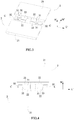
FIG. 1 is an enlarged perspective view of an embodiment of connecting pieces of a secondary battery according to the present invention. -
FIG. 2 is a top view of one connecting piece ofFIG. 1 . -
FIG. 3 is a perspective view before the connecting pieces are welded to tabs of cells in the secondary battery according to the present invention. -
FIG. 4 is a top view before the connecting pieces are welded to the tabs of the cells in the secondary battery according to the present invention with every two tab welding portions clamp a corresponding pair of tabs. -
FIG. 5 is a top view when the connecting pieces, the tabs of the cells and a cap plate of the secondary battery according to the present invention are welded with only a local two dimensional coordinate of the cap plate indicated. -
FIG. 6 is a front view after the connecting pieces are welded to the tabs of the cells and are bent in the secondary battery of the present invention with only the local two dimensional coordinate of the cap plate indicated. -
FIG. 7 is an enlarged view of a circle part ofFIG. 6 with only the local two dimensional coordinate of the cap plate indicated. -
FIG. 8 is a left view ofFIG. 6 with only the local two dimensional coordinate of the cap plate indicated. -
FIG. 9 is an enlarged view of a circle part ofFIG. 8 with only the local two dimensional coordinate of the cap plate indicated. -
FIG. 10 is a view illustrating a variation ofFIG. 2 . -
FIG. 11 is a view illustrating a variation ofFIG. 10 . -
FIGs. 12-14 are schematic assembled views of a secondary battery of the prior art, in which,FIG. 12 is a schematic view illustrating a connection relationship between tabs and electrode terminals before the tabs are bent in the secondary battery of the prior art;FIG. 13 is a perspective view of the secondary battery of the prior art;FIG. 14 is an enlarged view of a circle part ofFIG. 13 . - Reference numerals are represented as follows:
- 1 cap plate
- 11 electrode terminal
- 2 cell
- 21 main body
- 22 tab
- 221 planar portion
- 222 upright portion
- 3 connecting piece
- 31 tab welding portion
- 32 electrode terminal welding portion
- 33 transitional portion
- 331 hole
- L length direction of cap plate
- W width direction of cap plate
- T thickness direction of cap plate
- T' thickness direction of connecting piece
- W' transverse direction of connecting piece
- L' longitudinal direction of connecting piece
- C longitudinal central axis
- Hereinafter a secondary battery according to the present invention will be described in detail in combination with the figures.
- Referring to
FIGs. 1-11 , a secondary battery according to the present invention comprises acap plate 1 and at least onecell 2, thecap plate 1 is provided withelectrode terminals 11, eachcell 2 comprises amain body 21 andtabs 22 electrically connected to themain body 21 and extending from themain body 21. The secondary battery further comprises connectingpieces 3. Each connectingpiece 3 is parallel to thecap plate 1 and is positioned at an inside of thecap plate 1 in a thickness direction T of the cap plate 1 (inFIG. 5 , the inside is a side out of the paper surface; inFIGs. 6-9 , the inside is a side below thecap plate 1 in the thickness direction T of the cap plate 1), a longitudinal direction L' of each connectingpiece 3 is parallel to a length direction L of thecap plate 1, a transverse direction W' of each connectingpiece 3 is parallel to the width direction W of thecap plate 1, each connectingpiece 3 has: atab welding portion 31 for being welded to thecorresponding tab 22 of eachcell 2; and an electrodeterminal welding portion 32 connected to thetab welding portion 31 along the longitudinal direction L' of each connectingpiece 3 for being welded to thecorresponding electrode terminal 11 of thecap plate 1 so as to electrically connect thecorresponding electrode terminal 11 and thecorresponding tab 22 of eachcell 2. - In the secondary battery according to the present invention, the
corresponding tab 22 of eachcell 2 is welded to thetab welding portion 31 of the corresponding connectingpiece 3, thecorresponding electrode terminal 11 of thecap plate 1 is welded to the electrodeterminal welding portion 32 of the corresponding connectingpiece 3 so as to realize an electrical connection between thecorresponding electrode terminal 11 and thecorresponding tab 22 of eachcell 2. And during the electrical connection of the connectingpiece 3, each connectingpiece 3 need not be bent, which completely eliminates the requirement on bending property of each connectingpiece 3, and in turn eliminates chips generated by each connectingpiece 3 due to bending fatigue of each connectingpiece 3 and a risk that each connectingpiece 3 fractures due to bending fatigue of each connectingpiece 3. Moreover, with such a structure of each connectingpiece 3, the secondary battery of the present invention also increases an available space in the secondary battery from whole height, improves the production efficiency and reduces the production cost. - In addition, it should be noted that, a thickness direction T' of each connecting
piece 3 is parallel to the thickness direction T of thecap plate 1. - In the secondary battery according to the present invention, in an embodiment, referring to
FIGs. 3-5 , thetabs 22 of eachcell 2 extend straight from themain body 21 parallel to themain body 21 of eachcell 2 and parallel to the width direction W of thecap plate 1. With such a design, it is very suitable for a second battery which has a shape like a flat panel, so as to facilitate the thinness of an electronic device employing such a secondary battery. In an embodiment, referring toFIGs. 3-5 , the number of thecells 2 is two (i.e. the secondary battery comprises the two cells), the twomain bodies 21 of the twocells 2 are parallel to the width direction W of thecap plate 1 and are positioned respectively at two sides of each connectingpiece 3 in the transverse direction W' which is parallel to the width direction W of thecap plate 1, onetab 22 of onecell 2 and onetab 22 of theother cell 2 are electrically connected to thetab welding portion 31 of one corresponding connectingpiece 3 along the width direction W of thecap plate 1. With such a design, it is very suitable for a second battery which has a shape like a flat panel, so as to facilitate the thinness of an electronic device employing such a secondary battery. In addition, it should be noted that, the number of thecells 2 is not limited to this, and the number of thecells 2 may also be more than two. When the number of thecells 2 is more than two, thecells 2 are positioned respectively at the two sides of each connectingpiece 3 in the transverse direction W' which is parallel to the width direction W of thecap plate 1, and the number of thecells 2 and a thickness of eachcell 2 at one side may be different from the number of thecells 2 and a thickness of eachcell 2 at the other side, as long as it assures a total height of the stacked cell(s) 2 at one side is the same as a total height of the stacked cell(s) 2 at the other side. - In an embodiment, referring to
FIGs. 3-5 , the twocells 2 are symmetric about a longitudinal central axis C of each connectingpiece 3, the longitudinal central axis C of each connectingpiece 3 is parallel to the length direction L of thecap plate 1. - In an embodiment, referring to
FIGs. 6-9 , themain body 21 of eachcell 2 is upright in the thickness direction T of thecap plate 1; eachtab 22 of eachcell 2 has: aplanar portion 221 parallel to the width direction W of thecap plate 1 and weld to thetab welding portion 31; and anupright portion 222 extending parallel to themain body 21 and connected to theplanar portion 221 so as to form a reversed L shape together with theplanar portion 221. At this time, eachtab 22 is bent only once, so that it reduces the requirement on the bending property of eachtab 22, and greatly reduces a risk that eachtab 22 fractures due to bending fatigue of eachtab 22, reduces the production cost, improves the production efficiency and at the same time can increase an available space in the whole secondary battery from whole height. In addition, it should be noted that, although the bending of eachtab 22 shown inFIG. 9 seems similar to that shown inFIG. 13 , however, eachtab 22 inFIG.13 will be bent twice to form a horizontal U shape, eachtab 22 in the present invention is bent only once to form a reversed L shape due to a relative position of eachtab 22 provided to one correspondingmain body 21. - In an embodiment, the number of the
cells 2 is two (i.e. the secondary battery comprises the two cells 2) and the twocells 2 are arranged side by side along the width direction W of thecap plate 1, theplanar portion 221 of onetab 22 of onecell 2 and theplanar portion 221 of onetab 22 of theother cell 2 are welded to thetab welding portion 31 of one corresponding connectingpiece 3. But the number of thecells 2 is not limited to this, the number of thecells 2 can be more than two. When the number of thecells 2 is more than two, all thecells 2 can be arranged side by side along the width direction W of thecap plate 1, theplanar portions 221 of thecorresponding tabs 22 of all thecells 2 are stacked and welded to thetab welding portion 31 of one corresponding connectingpiece 3. - In an embodiment, each
electrode terminal 11 corresponds to one corresponding connectingpiece 3 and one correspondingtab 22 of eachcell 2 is welded to the one corresponding connectingpiece 3. In an embodiment, the connectingpiece 3 may be formed as a single metal sheet. In an embodiment, each connectingpiece 3 may be formed as metal sheets. Furthermore, a thickness of each of the metal sheets may be the same or different. In an embodiment, one correspondingtab 22 of eachcell 2 may be clamped between any two adjacent metal sheets of the connectingpiece 3. - In an embodiment, referring to
FIG. 1 and FIG. 2 , eachelectrode terminal 11 corresponds to two corresponding connectingpieces 3, one correspondingtab 22 of eachcell 2 is welded to the two corresponding connectingpieces 3. Referring toFIGs. 3-9 , one correspondingtab 22 of eachcell 2 is clamped between the twotab welding portions 31 of the two corresponding connectingpieces 3, and the two electrodeterminal welding portions 32 of the two corresponding connectingpieces 3 are stacked and fixed along the thickness direction T of thetop plate 1 so as to make the two corresponding connectingpieces 3 formed integrally. In an embodiment, thicknesses of the two corresponding connectingpieces 3 are the same. In an embodiment, each connectingpiece 3 can be formed as a single metal sheet. In an embodiment, each connectingpiece 3 can be formed as metal sheets. Furthermore, a thickness of each of the metal sheets may be the same or different. - In an embodiment, a shape of each connecting
piece 3 may be rectangle, circle, ellipse, arc, square or rectangle with rounded corners. But the shape of each connectingpiece 3 is not limited to that, but may be other shapes. - In an embodiment, referring to
FIGs. 1-5 ,FIG. 10 and FIG. 11 , each connectingpiece 3 may further has atransitional portion 33 positioned between thetab welding portion 31 and the electrodeterminal welding portion 32 and connecting thetab welding portion 31 and the electrodeterminal welding portion 32. - In an embodiment, referring to
FIGs. 1-5 andFIG. 10 , thetransitional portion 33, thetab welding portion 31 and the electrodeterminal welding portion 32 may cooperate with each other to form a recess. The formation of the recess can save material, particularly when eachelectrode terminal 11 corresponds to two corresponding connecting pieces 3 (referring toFIG. 1 andFIGs. 3-5 ), in order to allow the two corresponding connectingpieces 3 to clamp one correspondingtab 22 of eachcell 2, one connectingpiece 3 need be bent up. The formation of the recess further allows the one connectingpiece 3 to be bent down and flattened easily. In this embodiment, the formation of the recess is a preferred configuration related to thetransitional portion 33 in the present invention, of course the present invention is not limited to this, based on different widths and shapes of thetab welding portion 31 and the electrodeterminal welding portion 32, the size and shape of thetransitional portion 33 can be changed appropriately. - In an embodiment, referring to
FIG. 10 and FIG. 11 , thetransitional portion 33 may have ahole 331 provided between thetab welding portion 31 and the electrodeterminal welding portion 32. The provision of thehole 331 can save material, particularly when eachcorresponding electrode terminal 11 corresponds to two corresponding connecting pieces 3 (referring toFIG. 1 andFIGs. 3-5 ), in order to allow the two corresponding connectingpieces 3 to clamp one correspondingtab 22 of eachcell 2, one connectingpiece 3 need be bent up. The provision of thehole 331 further allows the one connectingpiece 3 to be bent down and flattened easily. - Finally, unless otherwise noted, each connecting
piece 3, eachtab 22, eachelectrode terminal 11 are electrically conductive. Furthermore, each connectingpiece 3, eachtab 22 and eachelectrode terminal 11 may be made of metal.
Claims (10)
- A secondary battery, comprising:a cap plate (1) provided with electrode terminals (11); andat least one cell (2), each cell (2) comprising a main body (21) and tabs (22) electrically connected to the main body (21) and extending from the main body (21);wherein
the secondary battery further comprises:connecting pieces (3), each connecting piece (3) is parallel to the cap plate (1) and positioned at an inside of the cap plate (1) in a thickness direction (T) of the cap plate (1), a longitudinal direction (L') of each connecting piece (3) is parallel to a length direction (L) of the cap plate (1), a transverse direction (W') of each connecting piece (3) is parallel to a width direction (W) of the cap plate (1), each connecting piece (3) has:a tab welding portion (31) for being welded to the corresponding tab (22) of each cell (2); andan electrode terminal welding portion (32) connected to the tab welding portion (31) along the longitudinal direction (L') of each connecting piece (3) for being welded to the corresponding electrode terminal (11) of the cap plate (1) so as to electrically connect the corresponding electrode terminal (11) and the corresponding tab (22) of each cell (2). - The secondary battery according to Claim 1, wherein
the secondary battery comprises the two cells (2), the two main bodies (21) of the two cells (2) are parallel to the width direction (W) of the cap plate (1) and are positioned respectively at two sides of each connecting piece (3) in the transverse direction (W') which is parallel to the width direction (W) of the cap plate (1),
one tab (22) of one cell (2) and one tab (22) of the other cell (2) are electrically connected to the tab welding portion (31) of one corresponding connecting piece (3) along the width direction (W) of the cap plate (1). - The secondary battery according to Claim 2, wherein the two cells (2) are symmetric about a longitudinal central axis (C) of each connecting piece (3), the longitudinal central axis (C) of each connecting piece (3) is parallel to the length direction (L) of the cap plate (1).
- The secondary battery according to Claim 1, wherein
the main body (21) of each cell (2) is upright along the thickness direction (T) of the cap plate (1);
each tab (22) of each cell (2) has:a planar portion (221) parallel to the width direction (W) of the cap plate (1) and welded to the tab welding portion (31); andan upright portion (222) extending parallel to the main body (21) and connected to the planar portion (221) so as form a reversed L shape together with the planar portion (221). - The secondary battery according to Claim 4, wherein
the secondary battery comprises the two cells (2) and the two cells (2) are arranged side by side along the width direction (W) of the cap plate (1);
the planar portion (221) of one tab (22) of one cell (2) and the planar portion (221) of one tab (22) of the other cell (2) are welded to the tab welding portion (31) of one corresponding connecting piece (3). - The secondary battery according to any one of Claims 1-5, wherein
each electrode terminal (11) corresponds to one corresponding connecting piece (3) and one corresponding tab (22) of each cell (2) is welded to the one corresponding connecting piece (3). - The secondary battery according to any one of Claims 1-5, wherein each electrode terminal (11) corresponds to two corresponding connecting pieces (3) and one corresponding tab (22) of each cell (2) is welded to the two corresponding connecting piece (3),
one corresponding tab (22) of each cell (2) is clamped in the two tab welding portions (31) of the two corresponding connecting pieces (3), and the two electrode terminal welding portions (32) of the two corresponding connecting pieces (3) along the thickness direction (T) of the top plate (1) are stacked and fixed so as to make the two corresponding connecting pieces (3) formed integrally. - The secondary battery according to Claim 1, wherein each connecting piece (3) is formed as a single metal sheet.
- The secondary battery according to Claim 1, wherein each connecting piece (3) is formed as metal sheets.
- The secondary battery according to any one of Claims 1-5, wherein each connecting piece (3) further has:a transitional portion (33) positioned between the tab welding portion (31) and the electrode terminal welding portion (32) and connecting the tab welding portion (31) and the electrode terminal welding portion (32).
Applications Claiming Priority (1)
| Application Number | Priority Date | Filing Date | Title |
|---|---|---|---|
| CN201610023257.8A CN106972144B (en) | 2016-01-14 | 2016-01-14 | Secondary battery |
Publications (2)
| Publication Number | Publication Date |
|---|---|
| EP3193386A1 true EP3193386A1 (en) | 2017-07-19 |
| EP3193386B1 EP3193386B1 (en) | 2018-10-24 |
Family
ID=57758534
Family Applications (1)
| Application Number | Title | Priority Date | Filing Date |
|---|---|---|---|
| EP17150790.8A Active EP3193386B1 (en) | 2016-01-14 | 2017-01-10 | Secondary battery |
Country Status (4)
| Country | Link |
|---|---|
| US (1) | US10199627B2 (en) |
| EP (1) | EP3193386B1 (en) |
| JP (1) | JP6261649B2 (en) |
| CN (1) | CN106972144B (en) |
Cited By (1)
| Publication number | Priority date | Publication date | Assignee | Title |
|---|---|---|---|---|
| CN114204220A (en) * | 2020-08-31 | 2022-03-18 | 比亚迪股份有限公司 | Battery cell, battery and battery pack |
Families Citing this family (17)
| Publication number | Priority date | Publication date | Assignee | Title |
|---|---|---|---|---|
| CN109698385B (en) * | 2017-10-20 | 2024-06-18 | 宁德时代新能源科技股份有限公司 | Secondary battery |
| CN111785904B (en) * | 2018-01-12 | 2021-08-17 | 宁德时代新能源科技股份有限公司 | Secondary batteries and automobiles |
| CN108598353B (en) * | 2018-01-16 | 2020-10-23 | 宁德时代新能源科技股份有限公司 | Rechargeable battery |
| CN111244388B (en) * | 2018-07-13 | 2022-02-25 | 宁德时代新能源科技股份有限公司 | Pole piece, manufacturing method of pole piece and secondary battery |
| CN108922993A (en) * | 2018-08-14 | 2018-11-30 | 江苏海基新能源股份有限公司 | The rectangular winding multi-pole lug lithium ion battery of one kind and its assembly method |
| CN109904379B (en) * | 2019-03-13 | 2022-02-01 | 芜湖天弋能源科技有限公司 | Power battery adapter plate welding structure and welding method thereof |
| CN110176571A (en) * | 2019-06-20 | 2019-08-27 | 湖北金泉新材料有限责任公司 | Connection sheet, comprising its battery and battery assemble method |
| CN114204224B (en) * | 2020-08-31 | 2023-06-13 | 比亚迪股份有限公司 | a battery |
| CN112310529B (en) * | 2020-10-27 | 2022-04-08 | 合肥国轩高科动力能源有限公司 | Lithium Ion Battery |
| CN112864539A (en) * | 2021-02-22 | 2021-05-28 | 昆山宝创新能源科技有限公司 | Power battery |
| CN113410585A (en) * | 2021-06-18 | 2021-09-17 | 厦门海辰新能源科技有限公司 | Lithium battery tab and switching piece welding module |
| CN115458872B (en) * | 2022-11-10 | 2023-03-31 | 瑞浦兰钧能源股份有限公司 | Adapter sheet of secondary battery |
| CN115377620A (en) * | 2022-08-11 | 2022-11-22 | 天能新能源(湖州)有限公司 | An electrode adapter piece and battery tab adapter structure |
| CN115377621B (en) * | 2022-08-11 | 2024-12-31 | 天能新能源(湖州)有限公司 | Switching piece and electrode switching structure |
| CN115548597B (en) * | 2022-11-29 | 2023-04-21 | 瑞浦兰钧能源股份有限公司 | A kind of welding method of secondary battery and battery thereof |
| CN116666909A (en) * | 2023-06-30 | 2023-08-29 | 厦门新能达科技有限公司 | Battery pack, electrical equipment and method for preparing the battery pack |
| CN118299768A (en) * | 2024-06-03 | 2024-07-05 | 宇恒电池股份有限公司 | Square lithium iron phosphate battery |
Citations (5)
| Publication number | Priority date | Publication date | Assignee | Title |
|---|---|---|---|---|
| US20090111004A1 (en) * | 2007-10-29 | 2009-04-30 | Samsung Sdi Co., Ltd. | Rechargeable battery |
| EP2136451A2 (en) * | 2008-06-20 | 2009-12-23 | Samsung SDI Co., Ltd. | Battery pack |
| EP2515358A1 (en) * | 2011-04-19 | 2012-10-24 | Samsung SDI Co., Ltd. | Battery pack |
| CN202585544U (en) * | 2012-03-06 | 2012-12-05 | 宁德新能源科技有限公司 | Power battery and top cover thereof |
| WO2014003361A1 (en) * | 2012-06-28 | 2014-01-03 | Sk Innovation Co.,Ltd. | Easily assembled all-in-one secondary battery module |
Family Cites Families (11)
| Publication number | Priority date | Publication date | Assignee | Title |
|---|---|---|---|---|
| JP4494731B2 (en) * | 2003-06-13 | 2010-06-30 | 三菱重工業株式会社 | Secondary battery and method for manufacturing secondary battery |
| US20120018989A1 (en) * | 2004-08-31 | 2012-01-26 | Automotive Technologies International, Inc. | Method for deploying a vehicular occupant protection system |
| US8557411B2 (en) * | 2009-08-14 | 2013-10-15 | Samsung Sdi Co., Ltd. | Secondary battery with a connection tab folded around an insulator and method of manufacturing the same |
| JP5618515B2 (en) * | 2009-09-25 | 2014-11-05 | 株式会社東芝 | battery |
| JP5357799B2 (en) * | 2010-02-09 | 2013-12-04 | 三菱重工業株式会社 | Secondary battery, secondary battery manufacturing apparatus and manufacturing method |
| JP5699955B2 (en) * | 2012-02-08 | 2015-04-15 | 株式会社豊田自動織機 | Power storage device and vehicle |
| CN202839828U (en) | 2012-07-19 | 2013-03-27 | 宁德新能源科技有限公司 | Power battery |
| CN102969477B (en) * | 2012-11-09 | 2014-11-12 | 中航锂电(洛阳)有限公司 | Lithium ion battery and tab and pole connecting pieces thereof |
| JP5812082B2 (en) * | 2013-11-19 | 2015-11-11 | 株式会社豊田自動織機 | Power storage device |
| JP6582500B2 (en) * | 2015-03-31 | 2019-10-02 | 株式会社Gsユアサ | Electricity storage element |
| CN204946983U (en) * | 2015-09-21 | 2016-01-06 | 宁德时代新能源科技有限公司 | Conductive vias sheet and secondary cell |
-
2016
- 2016-01-14 CN CN201610023257.8A patent/CN106972144B/en active Active
- 2016-05-17 JP JP2016098791A patent/JP6261649B2/en active Active
-
2017
- 2017-01-04 US US15/398,457 patent/US10199627B2/en active Active
- 2017-01-10 EP EP17150790.8A patent/EP3193386B1/en active Active
Patent Citations (5)
| Publication number | Priority date | Publication date | Assignee | Title |
|---|---|---|---|---|
| US20090111004A1 (en) * | 2007-10-29 | 2009-04-30 | Samsung Sdi Co., Ltd. | Rechargeable battery |
| EP2136451A2 (en) * | 2008-06-20 | 2009-12-23 | Samsung SDI Co., Ltd. | Battery pack |
| EP2515358A1 (en) * | 2011-04-19 | 2012-10-24 | Samsung SDI Co., Ltd. | Battery pack |
| CN202585544U (en) * | 2012-03-06 | 2012-12-05 | 宁德新能源科技有限公司 | Power battery and top cover thereof |
| WO2014003361A1 (en) * | 2012-06-28 | 2014-01-03 | Sk Innovation Co.,Ltd. | Easily assembled all-in-one secondary battery module |
Cited By (2)
| Publication number | Priority date | Publication date | Assignee | Title |
|---|---|---|---|---|
| CN114204220A (en) * | 2020-08-31 | 2022-03-18 | 比亚迪股份有限公司 | Battery cell, battery and battery pack |
| CN114204220B (en) * | 2020-08-31 | 2023-04-07 | 比亚迪股份有限公司 | Battery cell, battery and battery pack |
Also Published As
| Publication number | Publication date |
|---|---|
| US20170207437A1 (en) | 2017-07-20 |
| JP2017126547A (en) | 2017-07-20 |
| JP6261649B2 (en) | 2018-01-17 |
| EP3193386B1 (en) | 2018-10-24 |
| US10199627B2 (en) | 2019-02-05 |
| CN106972144A (en) | 2017-07-21 |
| CN106972144B (en) | 2023-03-17 |
Similar Documents
| Publication | Publication Date | Title |
|---|---|---|
| US10199627B2 (en) | Secondary battery | |
| US11811017B2 (en) | Battery unit and battery module | |
| CN110692149B (en) | Battery module, battery pack including the same, and vehicle | |
| EP3633766B1 (en) | Electrode member, electrode assembly, and secondary battery | |
| CN104009198B (en) | Lug jockey and there is the battery pack of lug jockey | |
| CN111902967B (en) | Bus bars and battery stacks | |
| JP2022529883A (en) | Battery unit and battery module | |
| JP6364757B2 (en) | Electric storage device and manufacturing method thereof | |
| US20110223478A1 (en) | Secondary battery and secondary battery module using the same | |
| KR102427427B1 (en) | Battery, battery pack having same and electric vehicle | |
| US20170256773A1 (en) | Conductive connecting plate for a lithium battery and a method for forming the same | |
| JP2017111896A (en) | Bus bar and electricity storage module | |
| KR101797693B1 (en) | Battery Pack Prepared Using Electrical Connecting Member for Battery Cell with Contact Bending Part | |
| CN217485520U (en) | Multi-cell secondary battery | |
| CN205376653U (en) | Secondary battery | |
| US10490799B2 (en) | Connector for power batteries, power battery module, power battery pack and vehicle | |
| US20190097201A1 (en) | Battery Module | |
| US20240274985A1 (en) | Battery pack | |
| CN222546611U (en) | A cylindrical battery core structure | |
| JP2014222683A (en) | Capacitor and process of manufacturing the same | |
| US20210305647A1 (en) | Secondary battery, method of manufacturing the same, and method of manufacturing conductive member for the same | |
| CN204857840U (en) | A power battery connecting sheet and a power battery pack and a vehicle having the same | |
| CN115832632A (en) | Electrode, cell, battery and electrical equipment | |
| CN208819940U (en) | Battery modules and its confluence component and confluence component | |
| CN208674050U (en) | The fixed structure of silicon wafer and the cathode assembly of X-ray tube |
Legal Events
| Date | Code | Title | Description |
|---|---|---|---|
| PUAI | Public reference made under article 153(3) epc to a published international application that has entered the european phase |
Free format text: ORIGINAL CODE: 0009012 |
|
| STAA | Information on the status of an ep patent application or granted ep patent |
Free format text: STATUS: REQUEST FOR EXAMINATION WAS MADE |
|
| 17P | Request for examination filed |
Effective date: 20170110 |
|
| AK | Designated contracting states |
Kind code of ref document: A1 Designated state(s): AL AT BE BG CH CY CZ DE DK EE ES FI FR GB GR HR HU IE IS IT LI LT LU LV MC MK MT NL NO PL PT RO RS SE SI SK SM TR |
|
| AX | Request for extension of the european patent |
Extension state: BA ME |
|
| GRAP | Despatch of communication of intention to grant a patent |
Free format text: ORIGINAL CODE: EPIDOSNIGR1 |
|
| STAA | Information on the status of an ep patent application or granted ep patent |
Free format text: STATUS: GRANT OF PATENT IS INTENDED |
|
| INTG | Intention to grant announced |
Effective date: 20180504 |
|
| RIC1 | Information provided on ipc code assigned before grant |
Ipc: H01M 2/26 20060101ALI20180420BHEP Ipc: H01M 10/04 20060101ALN20180420BHEP Ipc: H01M 2/04 20060101AFI20180420BHEP |
|
| GRAS | Grant fee paid |
Free format text: ORIGINAL CODE: EPIDOSNIGR3 |
|
| GRAA | (expected) grant |
Free format text: ORIGINAL CODE: 0009210 |
|
| STAA | Information on the status of an ep patent application or granted ep patent |
Free format text: STATUS: THE PATENT HAS BEEN GRANTED |
|
| AK | Designated contracting states |
Kind code of ref document: B1 Designated state(s): AL AT BE BG CH CY CZ DE DK EE ES FI FR GB GR HR HU IE IS IT LI LT LU LV MC MK MT NL NO PL PT RO RS SE SI SK SM TR |
|
| REG | Reference to a national code |
Ref country code: CH Ref legal event code: EP |
|
| REG | Reference to a national code |
Ref country code: IE Ref legal event code: FG4D |
|
| REG | Reference to a national code |
Ref country code: AT Ref legal event code: REF Ref document number: 1057739 Country of ref document: AT Kind code of ref document: T Effective date: 20181115 |
|
| REG | Reference to a national code |
Ref country code: DE Ref legal event code: R096 Ref document number: 602017000644 Country of ref document: DE |
|
| REG | Reference to a national code |
Ref country code: NL Ref legal event code: MP Effective date: 20181024 |
|
| REG | Reference to a national code |
Ref country code: LT Ref legal event code: MG4D |
|
| REG | Reference to a national code |
Ref country code: AT Ref legal event code: MK05 Ref document number: 1057739 Country of ref document: AT Kind code of ref document: T Effective date: 20181024 |
|
| PG25 | Lapsed in a contracting state [announced via postgrant information from national office to epo] |
Ref country code: NL Free format text: LAPSE BECAUSE OF FAILURE TO SUBMIT A TRANSLATION OF THE DESCRIPTION OR TO PAY THE FEE WITHIN THE PRESCRIBED TIME-LIMIT Effective date: 20181024 |
|
| PG25 | Lapsed in a contracting state [announced via postgrant information from national office to epo] |
Ref country code: IS Free format text: LAPSE BECAUSE OF FAILURE TO SUBMIT A TRANSLATION OF THE DESCRIPTION OR TO PAY THE FEE WITHIN THE PRESCRIBED TIME-LIMIT Effective date: 20190224 Ref country code: ES Free format text: LAPSE BECAUSE OF FAILURE TO SUBMIT A TRANSLATION OF THE DESCRIPTION OR TO PAY THE FEE WITHIN THE PRESCRIBED TIME-LIMIT Effective date: 20181024 Ref country code: BG Free format text: LAPSE BECAUSE OF FAILURE TO SUBMIT A TRANSLATION OF THE DESCRIPTION OR TO PAY THE FEE WITHIN THE PRESCRIBED TIME-LIMIT Effective date: 20190124 Ref country code: PL Free format text: LAPSE BECAUSE OF FAILURE TO SUBMIT A TRANSLATION OF THE DESCRIPTION OR TO PAY THE FEE WITHIN THE PRESCRIBED TIME-LIMIT Effective date: 20181024 Ref country code: HR Free format text: LAPSE BECAUSE OF FAILURE TO SUBMIT A TRANSLATION OF THE DESCRIPTION OR TO PAY THE FEE WITHIN THE PRESCRIBED TIME-LIMIT Effective date: 20181024 Ref country code: LT Free format text: LAPSE BECAUSE OF FAILURE TO SUBMIT A TRANSLATION OF THE DESCRIPTION OR TO PAY THE FEE WITHIN THE PRESCRIBED TIME-LIMIT Effective date: 20181024 Ref country code: LV Free format text: LAPSE BECAUSE OF FAILURE TO SUBMIT A TRANSLATION OF THE DESCRIPTION OR TO PAY THE FEE WITHIN THE PRESCRIBED TIME-LIMIT Effective date: 20181024 Ref country code: NO Free format text: LAPSE BECAUSE OF FAILURE TO SUBMIT A TRANSLATION OF THE DESCRIPTION OR TO PAY THE FEE WITHIN THE PRESCRIBED TIME-LIMIT Effective date: 20190124 Ref country code: FI Free format text: LAPSE BECAUSE OF FAILURE TO SUBMIT A TRANSLATION OF THE DESCRIPTION OR TO PAY THE FEE WITHIN THE PRESCRIBED TIME-LIMIT Effective date: 20181024 Ref country code: AT Free format text: LAPSE BECAUSE OF FAILURE TO SUBMIT A TRANSLATION OF THE DESCRIPTION OR TO PAY THE FEE WITHIN THE PRESCRIBED TIME-LIMIT Effective date: 20181024 |
|
| PG25 | Lapsed in a contracting state [announced via postgrant information from national office to epo] |
Ref country code: PT Free format text: LAPSE BECAUSE OF FAILURE TO SUBMIT A TRANSLATION OF THE DESCRIPTION OR TO PAY THE FEE WITHIN THE PRESCRIBED TIME-LIMIT Effective date: 20190224 Ref country code: SE Free format text: LAPSE BECAUSE OF FAILURE TO SUBMIT A TRANSLATION OF THE DESCRIPTION OR TO PAY THE FEE WITHIN THE PRESCRIBED TIME-LIMIT Effective date: 20181024 Ref country code: AL Free format text: LAPSE BECAUSE OF FAILURE TO SUBMIT A TRANSLATION OF THE DESCRIPTION OR TO PAY THE FEE WITHIN THE PRESCRIBED TIME-LIMIT Effective date: 20181024 Ref country code: RS Free format text: LAPSE BECAUSE OF FAILURE TO SUBMIT A TRANSLATION OF THE DESCRIPTION OR TO PAY THE FEE WITHIN THE PRESCRIBED TIME-LIMIT Effective date: 20181024 Ref country code: GR Free format text: LAPSE BECAUSE OF FAILURE TO SUBMIT A TRANSLATION OF THE DESCRIPTION OR TO PAY THE FEE WITHIN THE PRESCRIBED TIME-LIMIT Effective date: 20190125 |
|
| REG | Reference to a national code |
Ref country code: DE Ref legal event code: R097 Ref document number: 602017000644 Country of ref document: DE |
|
| PG25 | Lapsed in a contracting state [announced via postgrant information from national office to epo] |
Ref country code: CZ Free format text: LAPSE BECAUSE OF FAILURE TO SUBMIT A TRANSLATION OF THE DESCRIPTION OR TO PAY THE FEE WITHIN THE PRESCRIBED TIME-LIMIT Effective date: 20181024 Ref country code: IT Free format text: LAPSE BECAUSE OF FAILURE TO SUBMIT A TRANSLATION OF THE DESCRIPTION OR TO PAY THE FEE WITHIN THE PRESCRIBED TIME-LIMIT Effective date: 20181024 Ref country code: DK Free format text: LAPSE BECAUSE OF FAILURE TO SUBMIT A TRANSLATION OF THE DESCRIPTION OR TO PAY THE FEE WITHIN THE PRESCRIBED TIME-LIMIT Effective date: 20181024 |
|
| PG25 | Lapsed in a contracting state [announced via postgrant information from national office to epo] |
Ref country code: SK Free format text: LAPSE BECAUSE OF FAILURE TO SUBMIT A TRANSLATION OF THE DESCRIPTION OR TO PAY THE FEE WITHIN THE PRESCRIBED TIME-LIMIT Effective date: 20181024 Ref country code: MC Free format text: LAPSE BECAUSE OF FAILURE TO SUBMIT A TRANSLATION OF THE DESCRIPTION OR TO PAY THE FEE WITHIN THE PRESCRIBED TIME-LIMIT Effective date: 20181024 Ref country code: RO Free format text: LAPSE BECAUSE OF FAILURE TO SUBMIT A TRANSLATION OF THE DESCRIPTION OR TO PAY THE FEE WITHIN THE PRESCRIBED TIME-LIMIT Effective date: 20181024 Ref country code: SM Free format text: LAPSE BECAUSE OF FAILURE TO SUBMIT A TRANSLATION OF THE DESCRIPTION OR TO PAY THE FEE WITHIN THE PRESCRIBED TIME-LIMIT Effective date: 20181024 Ref country code: EE Free format text: LAPSE BECAUSE OF FAILURE TO SUBMIT A TRANSLATION OF THE DESCRIPTION OR TO PAY THE FEE WITHIN THE PRESCRIBED TIME-LIMIT Effective date: 20181024 |
|
| PLBE | No opposition filed within time limit |
Free format text: ORIGINAL CODE: 0009261 |
|
| STAA | Information on the status of an ep patent application or granted ep patent |
Free format text: STATUS: NO OPPOSITION FILED WITHIN TIME LIMIT |
|
| PG25 | Lapsed in a contracting state [announced via postgrant information from national office to epo] |
Ref country code: LU Free format text: LAPSE BECAUSE OF NON-PAYMENT OF DUE FEES Effective date: 20190110 |
|
| 26N | No opposition filed |
Effective date: 20190725 |
|
| REG | Reference to a national code |
Ref country code: BE Ref legal event code: MM Effective date: 20190131 |
|
| REG | Reference to a national code |
Ref country code: IE Ref legal event code: MM4A |
|
| PG25 | Lapsed in a contracting state [announced via postgrant information from national office to epo] |
Ref country code: SI Free format text: LAPSE BECAUSE OF FAILURE TO SUBMIT A TRANSLATION OF THE DESCRIPTION OR TO PAY THE FEE WITHIN THE PRESCRIBED TIME-LIMIT Effective date: 20181024 |
|
| PG25 | Lapsed in a contracting state [announced via postgrant information from national office to epo] |
Ref country code: BE Free format text: LAPSE BECAUSE OF NON-PAYMENT OF DUE FEES Effective date: 20190131 |
|
| PG25 | Lapsed in a contracting state [announced via postgrant information from national office to epo] |
Ref country code: IE Free format text: LAPSE BECAUSE OF NON-PAYMENT OF DUE FEES Effective date: 20190110 |
|
| PG25 | Lapsed in a contracting state [announced via postgrant information from national office to epo] |
Ref country code: TR Free format text: LAPSE BECAUSE OF FAILURE TO SUBMIT A TRANSLATION OF THE DESCRIPTION OR TO PAY THE FEE WITHIN THE PRESCRIBED TIME-LIMIT Effective date: 20181024 |
|
| PG25 | Lapsed in a contracting state [announced via postgrant information from national office to epo] |
Ref country code: MT Free format text: LAPSE BECAUSE OF NON-PAYMENT OF DUE FEES Effective date: 20190110 |
|
| REG | Reference to a national code |
Ref country code: CH Ref legal event code: PL |
|
| REG | Reference to a national code |
Ref country code: DE Ref legal event code: R079 Ref document number: 602017000644 Country of ref document: DE Free format text: PREVIOUS MAIN CLASS: H01M0002040000 Ipc: H01M0050147000 |
|
| PG25 | Lapsed in a contracting state [announced via postgrant information from national office to epo] |
Ref country code: LI Free format text: LAPSE BECAUSE OF NON-PAYMENT OF DUE FEES Effective date: 20200131 Ref country code: CH Free format text: LAPSE BECAUSE OF NON-PAYMENT OF DUE FEES Effective date: 20200131 |
|
| PG25 | Lapsed in a contracting state [announced via postgrant information from national office to epo] |
Ref country code: CY Free format text: LAPSE BECAUSE OF FAILURE TO SUBMIT A TRANSLATION OF THE DESCRIPTION OR TO PAY THE FEE WITHIN THE PRESCRIBED TIME-LIMIT Effective date: 20181024 |
|
| PG25 | Lapsed in a contracting state [announced via postgrant information from national office to epo] |
Ref country code: MK Free format text: LAPSE BECAUSE OF FAILURE TO SUBMIT A TRANSLATION OF THE DESCRIPTION OR TO PAY THE FEE WITHIN THE PRESCRIBED TIME-LIMIT Effective date: 20181024 |
|
| REG | Reference to a national code |
Ref country code: FR Ref legal event code: PLFP Year of fee payment: 7 |
|
| P01 | Opt-out of the competence of the unified patent court (upc) registered |
Effective date: 20230516 |
|
| REG | Reference to a national code |
Ref country code: DE Ref legal event code: R082 Ref document number: 602017000644 Country of ref document: DE Ref country code: DE Ref legal event code: R081 Ref document number: 602017000644 Country of ref document: DE Owner name: CONTEMPORARY AMPEREX TECHNOLOGY (HONG KONG) LT, HK Free format text: FORMER OWNER: CONTEMPORARY AMPEREX TECHNOLOGY CO., LTD., NINGDE CITY, FUJIAN, CN |
|
| REG | Reference to a national code |
Ref country code: GB Ref legal event code: 732E Free format text: REGISTERED BETWEEN 20240801 AND 20240807 |
|
| REG | Reference to a national code |
Ref country code: HU Ref legal event code: GB9C Owner name: CONTEMPORARY AMPEREX TECHNOLOGY (HONG KONG) LIMITED, HK Free format text: FORMER OWNER(S): CONTEMPORARY AMPEREX TECHNOLOGY CO., LIMITED, CN Ref country code: HU Ref legal event code: FH1C Free format text: FORMER REPRESENTATIVE(S): DANUBIA SZABADALMI ES JOGI IRODA KFT., HU Representative=s name: DANUBIA SZABADALMI ES JOGI IRODA KFT., HU |
|
| PGFP | Annual fee paid to national office [announced via postgrant information from national office to epo] |
Ref country code: GB Payment date: 20251120 Year of fee payment: 10 |
|
| PGFP | Annual fee paid to national office [announced via postgrant information from national office to epo] |
Ref country code: FR Payment date: 20251124 Year of fee payment: 10 |
|
| PGFP | Annual fee paid to national office [announced via postgrant information from national office to epo] |
Ref country code: HU Payment date: 20251212 Year of fee payment: 10 |
|
| PGFP | Annual fee paid to national office [announced via postgrant information from national office to epo] |
Ref country code: DE Payment date: 20251119 Year of fee payment: 10 |