EP3193278A1 - Magnetic ink character reader and magnetic ink character reading method - Google Patents
Magnetic ink character reader and magnetic ink character reading method Download PDFInfo
- Publication number
- EP3193278A1 EP3193278A1 EP17151302.1A EP17151302A EP3193278A1 EP 3193278 A1 EP3193278 A1 EP 3193278A1 EP 17151302 A EP17151302 A EP 17151302A EP 3193278 A1 EP3193278 A1 EP 3193278A1
- Authority
- EP
- European Patent Office
- Prior art keywords
- reader
- magnetic ink
- signal waveform
- magnetic
- medium
- Prior art date
- Legal status (The legal status is an assumption and is not a legal conclusion. Google has not performed a legal analysis and makes no representation as to the accuracy of the status listed.)
- Granted
Links
Images


Classifications
-
- G—PHYSICS
- G06—COMPUTING OR CALCULATING; COUNTING
- G06V—IMAGE OR VIDEO RECOGNITION OR UNDERSTANDING
- G06V30/00—Character recognition; Recognising digital ink; Document-oriented image-based pattern recognition
- G06V30/10—Character recognition
- G06V30/22—Character recognition characterised by the type of writing
- G06V30/224—Character recognition characterised by the type of writing of printed characters having additional code marks or containing code marks
- G06V30/2253—Recognition of characters printed with magnetic ink
-
- G—PHYSICS
- G06—COMPUTING OR CALCULATING; COUNTING
- G06Q—INFORMATION AND COMMUNICATION TECHNOLOGY [ICT] SPECIALLY ADAPTED FOR ADMINISTRATIVE, COMMERCIAL, FINANCIAL, MANAGERIAL OR SUPERVISORY PURPOSES; SYSTEMS OR METHODS SPECIALLY ADAPTED FOR ADMINISTRATIVE, COMMERCIAL, FINANCIAL, MANAGERIAL OR SUPERVISORY PURPOSES, NOT OTHERWISE PROVIDED FOR
- G06Q20/00—Payment architectures, schemes or protocols
- G06Q20/04—Payment circuits
- G06Q20/042—Payment circuits characterized in that the payment protocol involves at least one cheque
-
- G—PHYSICS
- G06—COMPUTING OR CALCULATING; COUNTING
- G06F—ELECTRIC DIGITAL DATA PROCESSING
- G06F2218/00—Aspects of pattern recognition specially adapted for signal processing
- G06F2218/08—Feature extraction
- G06F2218/10—Feature extraction by analysing the shape of a waveform, e.g. extracting parameters relating to peaks
Definitions
- the present invention relates in general to a field of commercial or consumer transaction and, in particular, to a magnetic ink character reader and a magnetic ink character reading method, as well as a check reader.
- a check may be used as a method of payment.
- Information such as a check number may be shown in magnetic ink characters at a predetermined position on a front surface of the check along with a monetary amount and an authorizing signature.
- the magnetic ink characters are read by a magnetic ink character reader (MICR) including a magnetic head.
- MICR magnetic ink character reader
- a magnetic head is disposed in a transport path of the check, and the magnetic ink characters are recognized using data obtained by scanning the check in a first direction and then a second direction opposite to the first direction.
- a magnetic ink character reader comprising:
- the reader is a magnetic head.
- the transport unit comprises at least one roller configured to engage the medium.
- the magnetic ink character reader further comprises:
- the processor is configured to compare one of the signal waveform and the inverted signal waveform to a reference waveform and determine a similarity value for the reference waveform in comparison to the one of the signal waveform and the inverted signal waveform.
- the magnetic ink character reader further comprises:
- the notification unit is preferably a display.
- the invention also relates to a method of reading magnetic ink characters printed on a medium, the method comprising:
- recognizing the magnetic ink characters includes comparing one of the signal waveform and the inverted signal waveform to a reference waveform to determine a similarity value for the reference waveform in comparison to the one of the signal waveform and the inverted signal waveform.
- the method further comprises:
- the medium is preferably a check.
- the magnetic ink characters are printed on the medium in a font type complying with a standard magnetic ink character recognition code.
- moving the medium along the transport path in the first direction preferably comprises engaging the medium with at least one pair of rollers positioned along the transport path.
- the invention further relates to a check reader, comprising:
- the check reader further comprises:
- a pre-established forward reading direction of the second magnetic head is opposite the pre-established forward reading direction of the first magnetic head.
- the check reader further comprises:
- a pre-established forward reading direction of the second magnetic head matches the pre-established forward reading direction of the first magnetic head.
- a magnetic ink character reader includes a transport unit configured to move a medium along a transport path, a reader configured to magnetically read magnetic ink characters printed on the medium, while the medium is moved along the transport path and to output a signal waveform corresponding to the magnetic ink characters, the reader having a forward reading direction along the transport path for the medium, and a processor configured to compare a transportation direction of the medium through the reader to the forward reading direction of the reader, and to invert, in horizontal and vertical directions, the signal waveform output from the reader when the transportation direction is not the forward reading direction.
- the processor is further configured to perform magnetic character recognition using the signal waveform from the reader when the transportation direction is the forward reading direction and the inverted signal waveform when the transportation direction is a reverse reading direction opposite the forward reading direction.
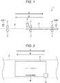
- FIG. 1 is a diagram illustrating a schematic configuration of a magnetic ink character reader.
- a magnetic ink character reader 1 has a sheet transport path 2 along which a sheet P (a medium to be read) is transported.
- the sheet P is a sheet medium of a check or other document related to a financial or consumer transaction.
- Information such as a check number, a routing number, and/or an account number is printed in magnetic ink characters M at a predetermined position on a front surface of the sheet P with other information such as an amount of money and signature (see FIG. 2 ).
- the magnetic ink characters M are generally printed in a font type complying with a standard such as E-13B and CMC-7 (magnetic ink character recognition code).
- Transport rollers 3 are provided along the sheet transport path 2, and these transport the sheet P along the sheet transport path 2 in reciprocating directions (indicated by an arrow A and an arrow B).
- a sheet sensor 4 is provided proximate to both ends of the sheet transport path 2, and detects the sheet P while it is on the sheet transport path 2.
- the sheet sensor 4 provided on a left end of the sheet transport path 2 is referred to as a sheet sensor 4L
- the sheet sensor 4 provided on a right end of the sheet transport path 2 is referred to as a sheet sensor 4R.
- a magnetic head 5 magnetically reads the magnetic ink characters M printed on the sheet P, and outputs a signal waveform corresponding to an image of the magnetic ink characters M.
- one or more magnetic heads 5 are provided at such positions where the magnetic head(s) 5 can read the magnetic ink characters M from the sheet P.
- FIG. 1 illustrates an example in which a magnetic head 5 is provided above the sheet transport path 2. However, the disclosure is not limited thereto. A magnetic head 5 may instead, or in addition, be provided below the sheet transport path 2.
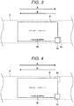
- FIG. 2 to FIG. 4 are diagrams schematically illustrating examples of installation positions of the magnetic heads 5 (5a to 5e), and illustrate a state in which the sheet transport path 2 is viewed from the top.
- the magnetic ink characters M are printed on the front surface of the sheet P in such a format that the magnetic ink characters M are arranged on a lower side in a longitudinal direction thereof.
- FIG. 2 illustrates an example in which a magnetic head 5a is provided.
- the magnetic head 5a is provided above the sheet transport path 2, and on one side (right page side in FIG. 2 ) along the longitudinal direction of the transport path 2.
- the magnetic head 5a can read the magnetic ink characters M.
- this particular configuration is referred to as a "first configuration.”
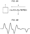
- FIG. 3 schematically illustrates an example in which two magnetic heads 5b and 5c are provided at different positions from each other.
- the magnetic head 5b is provided above the sheet transport path 2, and on one side in the longitudinal direction.
- the magnetic head 5c is provided below the sheet transport path 2 at a position where the magnetic head 5c faces the magnetic head 5b. That is, as depicted in FIG. 3 , magnetic head 5b at least partially overlaps magnetic head 5c when viewed from above the transport path 2.
- the magnetic head 5c can read the magnetic ink characters M.
- this particular configuration is referred to as a "second configuration".
- FIG. 4 schematically illustrates an example in which two magnetic heads 5d and 5e are provided at different positions from each other.
- the magnetic head 5d is provided above the sheet transport path 2 and on one side of the transport path 2.
- the magnetic head 5e is provided below the sheet transport path 2 and on the other side of the transport path 2.
- the magnetic head 5e can read the magnetic ink characters M.
- this particular configuration is referred to as a "third configuration".
- the magnetic heads 5 can read the magnetic ink characters M from the sheet P when the sheet P is inserted into the sheet transport path 2 in particular directions.
- the installation position of the magnetic head 5 determines a reading direction in which the magnetic head 5 can read the magnetic ink characters M, that is, uniquely determines a suitable transport direction (hereinafter, referred to as a forward direction) of the sheet P that enables the magnetic head 5 to read the magnetic ink characters M.
- a regular reading direction is defined as reading a character string of the magnetic ink characters M from the right end to the left end (when viewing the front surface).
- a direction of the arrow A is would be the forward direction for the magnetic head 5a.
- the direction of the arrow A would be the forward direction for the magnetic head 5b and a direction of the arrow B would be the forward direction for the magnetic head 5c.
- the direction of the arrow A would be the forward direction for the magnetic head 5d and the direction of the arrow A would also be the forward direction for the magnetic head 5e.
- An identifier identifying each of the magnetic heads 5 (5a to 5e) that is, providing a correspondence relationship between the installation position of each magnetic head 5 and the respective forward direction (or reverse direction) can be stored in a ROM 12 or the like as setting information.
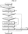
- FIGs. 5A and 6A are diagrams illustrating an example of the magnetic ink characters M and FIGs. 5B and 6B are examples of a signal waveform obtained when the magnetic ink characters M are read in the indicated direction of FIGs. 5A and 6A , respectively.
- the magnetic ink characters M include a string of numbers 1 to 0 and control characters on either end of the number string.
- FIG. 5A illustrates an example in which the magnetic ink characters M are transported in the arrow A direction (forward direction) in the diagram at a speed of approximately 8 ips (inches per second) with respect to the magnetic head 5 having a gap length of 0.076 mm.
- the magnetic head 5 outputs a signal waveform in accordance with shapes of the magnetic ink characters M from the right end to the left end.
- the signal waveform represents change in magnetic charge per a predetermined sampling period, and thus has a waveform in accordance with the shapes of the magnetic ink characters M along the reading direction.
- FIG. 6A illustrates an example in which the magnetic ink characters M are transported in the arrow B direction (reverse direction) in the diagram at the same speed with respect to the magnetic head 5 having a gap length of 0.076 mm.
- the magnetic head 5 outputs a signal waveform in accordance with shapes of the magnetic ink characters M from the left end to the right end.
- FIG. 5B when signal waveforms of FIG. 5B and FIG. 6B are compared, it can be seen that the signal waveforms are different from each other. However, a signal waveform obtained by inverting, vertically and horizontally, the signal waveform of FIG. 5B will approximately match the signal waveform of FIG. 6B .
- the vertical direction in FIG. 5B may be referred to as a lateral waveform direction and, the horizontal direction in FIG. 5B may be referred to as a longitudinal waveform direction.
- the particular signal waveform obtained from the magnetic head 5 varies depending on the reading direction of the magnetic ink characters M. Therefore, when the sheet P is transported in the reverse direction, there is a problem that the magnetic ink characters M cannot be properly recognized from the signal waveform.
- the magnetic ink character reader 1 of the present embodiment obtains the same signal waveform for a reverse reading of the magnetic ink character M as for a forward reading of the magnetic ink characters M by correcting the signal waveform for the reverse reading.
- a control configuration of the magnetic ink character reader 1 will be described.
- FIG. 7 is a diagram illustrating an example of the control configuration of the magnetic ink character reader 1.
- the magnetic ink character reader 1 includes a central processing unit (CPU) 11, a read only memory (ROM) 12, a random access memory (RAM) 13, a display unit 14, an operation unit 15, a sheet detection unit 16, and a sheet transport mechanism 17, as well as the magnetic head 5 (see e.g., FIG. 1 ).
- the CPU 11 integrally controls an operation of the magnetic ink character reader 1 by executing a program stored in the ROM 12.
- the CPU 11 provides various functional units, which will be described, by executing a program stored in the ROM 12.
- the ROM 12 stores various programs (instructions) which can be executed by the CPU 11 and various types of setting information related to operation of the magnetic ink character reader 1.
- the RAM 13 may temporarily store data and programs when the CPU 11 executes various programs.
- the display unit 14 includes a display device, such as a liquid crystal display (LCD), and displays various types of information under the control of the CPU 11.
- the operation unit 15 includes an input device such as an operation switch, and outputs operation contents that are input through the input device, to the CPU 11.
- the sheet detection unit 16 includes the sheet sensors 4 (see e.g., FIG. 1 ), and detects a position of the sheet P on the sheet transport path 2 based on outputs of the sheet sensors 4.
- the sheet transport mechanism 17 includes the sheet transport path 2 and the transport rollers 3 (see e.g., FIG. 1 ), and includes a drive motor for each of the transport rollers 3 and a drive circuit for controlling the drive motor.
- the sheet transport mechanism 17 can transport an inserted sheet P in the reciprocating directions of the arrow A and arrow B directions of FIG. 1 under the control of the CPU 11.
- the CPU 11 provides a transport control unit 21, a determination unit 22, a correction unit 23, a recognition unit 24, and an output control unit 25.
- the transport control unit 21 controls the transport direction of the sheet P on the sheet transport path 2 by controlling the sheet transport mechanism 17. Specifically, the transport control unit 21 determines the transport direction of the sheet P based on a detected sheet P position from the sheet detection unit 16.
- the sheet detection unit 16 detects a position of the sheet P by the output or response of sheet sensor 4L. In this case, the transport control unit 21 then controls the sheet transport mechanism 17 (e.g., one or more roller 3) so as to transport the sheet P in the direction of the arrow A along the sheet transport path 2.
- the sheet detection unit 16 detects the position of the sheet P by the output or response of sheet sensor 4R. In this case, the transport control unit 21 then controls the sheet transport mechanism 17 so as to transport the sheet P in the direction of the arrow B along the transport path 2.
- the determination unit 22 determines whether or not the transport direction of the sheet P is the forward direction (first direction) or the reverse direction (second direction) at the time of the reading. More specifically, the determination unit 22 compares whether or not the transport direction of the sheet P and the forward direction corresponding to an identifier (or installation position) of the magnetic head 5 being used to read the magnetic ink characters M coincide with each other.
- the identifier of the magnetic head 5 is stored as setting information.
- the determination unit 22 determines whether or not the sheet P is being or was transported in the arrow A direction.
- the determination unit 22 determines that the sheet P is transported in the forward direction (with respect to magnetic head 5a).
- the determination unit 22 determines that the sheet P is transported in the reverse direction (with respect to magnetic head 5a).
- the determination unit 22 determines whether or not the sheet P is being or was transported in the arrow A direction.
- the determination unit 22 determines that the sheet P is transported in the forward direction (with respect to magnetic head 5b). If the sheet P is transported in the arrow B direction, the determination unit 22 determines that the sheet P is transported in the reverse direction (with respect to magnetic head 5b).
- the determination unit 22 determines whether or not the sheet P is being or was transported in the arrow B direction.
- the determination unit 22 determines that the sheet P is transported in the forward direction (with respect to magnetic head 5c). If the sheet P is transported in the arrow A direction, the determination unit 22 determines that the sheet P is transported in the reverse direction (with respect to magnetic head 5c).
- the determination unit 22 determines whether or not the sheet P is being or was transported in the arrow A direction.
- the determination unit 22 determines that the sheet P is transported in the forward direction (with respect to either magnetic head 5d or 5e). If the sheet P is transported in the arrow B direction, the determination unit 22 determines that the sheet P is transported in the reverse direction (with respect to either magnetic head 5d or 5e).
- the determination unit 22 determines that the orientation/direction of the sheet P is inappropriate. In this case, the determination unit 22 performs notification by displaying on the display unit 14 a notification screen to instruct change of the orientation/direction of the sheet P.
- the correction unit 23 performs a correction to invert, in the horizontal and vertical directions, a signal waveform output by the magnetic head 5.
- the signal waveform becomes substantially equivalent to a signal waveform that would be obtained by a reading in the forward direction.
- the recognition unit 24 recognizes the magnetic ink characters M based on the signal waveform output by the magnetic head 5 without inversion. In addition, when the determination unit 22 determines that the transport direction of the sheet P is the reverse direction, the recognition unit 24 recognizes the magnetic ink characters M based on the corrected (inverted) signal waveform provided by the correction unit 23. Specifically, the recognition unit 24 collates either the signal waveform read by the magnetic head 5 or the corrected signal waveform provided by the correction unit 23, to a registration waveform pattern for character recognition in which a signal waveform pattern for each character has been previously registered or established.
- the recognition unit 24 obtains a degree of similarity between the registration waveform patterns and the signal waveforms, and recognizes characters in the signal waveforms by the degrees of similarity with the registration waveform pattern (when, for example, the degree of similarity is equal to or greater than a reference value).
- the output control unit 25 outputs the characters as recognized by the recognition unit 24 to the display unit 14.
- An output method is not particularly limited, and may include output the characters as recognized to a device other than the display unit 14.
- the output control unit 25 may output the characters as read to the printer.
- the transport control unit 21 waits (idles) until the sheet P is inserted into the sheet transport path 2. Insertion of the sheet P into the transport may be detected based on a detection result of the sheet detection unit 16 (step S11; No sheet inserted).
- step S11; Yes the transport control unit 21 transports the sheet P toward an opposite end from that at which the sheet P has been inserted (step S12).
- the determination unit 22 detects whether or not the magnetic head 5 reads the magnetic ink characters M during the transport of the sheet P along the sheet transport path (step S13).
- the determination unit 22 determines that the direction/orientation of the sheet P is inappropriate. Accordingly, the determination unit 22 displays on the display unit 14 a notification screen that prompts to change the direction/orientation of the sheet P (step S 14), and terminates the processing.
- step S13 If the magnetic head 5 reads the magnetic ink characters M (step S13; Yes), the determination unit 22 refers to the setting information (stored, for example, in ROM 12). Next, the determination unit 22 determines whether or not the transport direction of the sheet P coincides with the forward direction of the magnetic head 5 which has read the magnetic ink characters M (step S15). Here, when the determination unit 22 determines that the sheet P transport direction and the forward direction of the magnetic head 5, which has read the magnetic ink characters M coincide with each other, that is, when the determination unit 22 determines that the transport direction is the forward direction with respect to magnetic head 5 (step S15; Yes), the process proceeds directly to step S17 (bypassing step S16).
- the correction unit 23 inverts, in the horizontal and vertical directions, the signal waveform provided by the magnetic head 5 (step S16), and the process proceeds to step S17.
- step S17 the recognition unit 24 collates the signal waveform read by the magnetic head 5 or the signal waveform inverted by the correction unit 23, and the registration waveform patterns, and recognizes the characters corresponding to the signal waveform from the magnetic head 5(corrected or uncorrected as the case may be)(step S17). Accordingly, the output control unit 25 outputs the characters recognized by the recognition unit 24 to the display unit 14 or the like (step S18), and terminates the process.
- the magnetic ink character reader 1 determines whether or not the sheet P (magnetic ink character M) is being or has been transported in the forward direction with respect to the magnetic reader 5 that reads the magnetic ink characters M. In addition, when the sheet P (magnetic ink character M) is transported in the reverse direction with respect to the magnetic head that reads the magnetic ink characters M, the magnetic ink character reader 1 inverts the signal waveform read by the magnetic head 5, and recognizes the magnetic ink characters M based on the corrected/inverted signal waveform. With this process, even when the sheet P is transported along either of the arrow A or the arrow B directions illustrated in FIG. 1 , the magnetic ink character reader 1 can correctly read the magnetic ink characters M.
- the possible installation positions of the magnetic head 5 are not limited to the first to third configurations, and can be appropriately changed in accordance with an expected format of the sheet P.
- one magnetic head 5 may be provided below the sheet transport path 2, and the magnetic heads 5 may be provided below and above the sheet transport path 2 or on both sides of the transport path 2 in the longitudinal direction.
- a transportation method of the sheet P is not limited to the particular examples.
- the transport control unit 21 may initially transport the sheet P toward an opposite end from the sheet insertion end and then, transport the sheet P in the reverse direction so as to return the sheet P to the insertion end.
- a magnetic head 5 can read the sheet P two times, once in a forward path direction and once in a backward path direction.
- the determination unit 22 determines whether the sheet P transport direction is the forward direction or the reverse direction for each of the forward path and the backward path, and the correction unit 23 inverts the signal waveform for the readings made in the reverse direction.
- the recognition unit 24 may perform the character recognition by using both signal waveforms obtained in the two readings, or may perform the character recognition by using a signal waveform obtained for any one of the readings.
- a program executed by the magnetic ink character reader 1 may be provided as a recording on a non-volatile computer readable recording medium such as a floppy disk, a compact disc (CD), a compact disc-recordable (CD-R), a compact disk read only memory (CD-ROM), a digital versatile disc (DVD), an SD memory card, and a universal serial bus (USB) memory, as an installable format file or an executable format file.
- a non-volatile computer readable recording medium such as a floppy disk, a compact disc (CD), a compact disc-recordable (CD-R), a compact disk read only memory (CD-ROM), a digital versatile disc (DVD), an SD memory card, and a universal serial bus (USB) memory, as an installable format file or an executable format file.
- the program executed by the magnetic ink character reader 1 may be configured to operate on a computer connected to a network such as the Internet, and may be downloaded, operated, implemented or the like via a network.
- each functional unit of the magnetic ink character reader 1 can also be separately realized or implemented in hardware/circuitry as one or more processing circuit in the magnetic ink character reader 1.
- a processing circuit includes hardware such as a processor (for example, CPU 11) described above, and an application specific integrated circuit (ASIC) and a printed circuit module configured to realize each described function.
Landscapes
- Engineering & Computer Science (AREA)
- Physics & Mathematics (AREA)
- General Physics & Mathematics (AREA)
- Theoretical Computer Science (AREA)
- Business, Economics & Management (AREA)
- Computer Vision & Pattern Recognition (AREA)
- Multimedia (AREA)
- Accounting & Taxation (AREA)
- Strategic Management (AREA)
- General Business, Economics & Management (AREA)
- Character Input (AREA)
Abstract
Description
- The present invention relates in general to a field of commercial or consumer transaction and, in particular, to a magnetic ink character reader and a magnetic ink character reading method, as well as a check reader.
- In commercial or consumer transactions, a check may be used as a method of payment. Information such as a check number may be shown in magnetic ink characters at a predetermined position on a front surface of the check along with a monetary amount and an authorizing signature. The magnetic ink characters are read by a magnetic ink character reader (MICR) including a magnetic head.
- Usually, a magnetic head is disposed in a transport path of the check, and the magnetic ink characters are recognized using data obtained by scanning the check in a first direction and then a second direction opposite to the first direction.
- However, such related art requires reading the check at least twice in different directions and is often ineffective and slow.
- To solve such problems, there is provided a magnetic ink character reader, comprising:
- a transport unit configured to move a medium along a transport path;
- a reader configured to magnetically read magnetic ink characters printed on the medium, while the medium is being moved along the transport path and to output a signal waveform corresponding to the magnetic ink characters, the reader having a forward reading direction along the transport path for the medium; and
- a processor configured to compare a transportation direction of the medium through the reader to the forward reading direction of the reader, and to invert, in horizontal and vertical directions, the signal waveform output from the reader when the transportation direction is not the forward reading direction,
- wherein the processor is further configured to perform magnetic character recognition using the signal waveform from the reader when the transportation direction is the forward reading direction and the inverted signal waveform when the transportation direction is a reverse reading direction opposite the forward reading direction.
- Preferably, the reader is a magnetic head.
- Preferably still, the transport unit comprises at least one roller configured to engage the medium.
- Preferably yet, the magnetic ink character reader further comprises:
- a detector including at least one sensor configured to detect a presence of the medium along the transport path.
- Suitably, the processor is configured to compare one of the signal waveform and the inverted signal waveform to a reference waveform and determine a similarity value for the reference waveform in comparison to the one of the signal waveform and the inverted signal waveform.
- Suitably still, the magnetic ink character reader further comprises:
- a notification unit configured to indicate an orientation of the medium is to be changed when the reader cannot read the magnetic ink character when the medium is transported along the transport path.
- In the above magnetic ink character reader, the notification unit is preferably a display.
- The invention also relates to a method of reading magnetic ink characters printed on a medium, the method comprising:
- moving the medium along a transport path in a first direction;
- reading the magnetic ink characters printed on the medium with a reader that outputs a signal waveform corresponding to the magnetic ink characters, the reader being configured to have a forward reading direction along the transport path;
- comparing the first direction to the forward reading direction of the reader;
- inverting, in the horizontal and vertical direction, the signal wave output from the reader to provide an inverted signal waveform when the first direction is not the forward reading direction; and
- recognizing the magnetic ink characters using the signal waveform output from the reader when the first direction is the forward reading direction and using the inverted signal waveform when the first direction is not the forward reading direction.
- Preferably, recognizing the magnetic ink characters includes comparing one of the signal waveform and the inverted signal waveform to a reference waveform to determine a similarity value for the reference waveform in comparison to the one of the signal waveform and the inverted signal waveform.
- Preferably still, the method further comprises:
- indicating with a notification unit that an orientation of the medium is to be changed when the reader cannot read the magnetic ink characters when the medium is transported along the transport path in the first direction.
- In the above method, the medium is preferably a check.
- Preferably yet, the magnetic ink characters are printed on the medium in a font type complying with a standard magnetic ink character recognition code.
- In the above method, moving the medium along the transport path in the first direction preferably comprises engaging the medium with at least one pair of rollers positioned along the transport path.
- The invention further relates to a check reader, comprising:
- a roller pair configured to move a check along a transport path;
- a first magnetic head positioned to read magnetic ink characters disposed on a surface of the check while the check is moving along the transport path in a particular orientation and to generate a signal waveform corresponding to the magnetic ink characters disposed on the surface of the check when the check is in the particular orientation;
- a sensor disposed proximate to a position along the transport path, the sensor configured to detect a presence of the check at the position; and
- a controller configured to:
- determine a direction of travel of the check along the transport path according to an output of the sensor,
- compare the direction of travel to a pre-established forward reading direction of the first magnetic head,
- when the pre-established forward reading direction matches the direction of travel, use the signal waveform to recognize the magnetic ink characters, and
- when the pre-established forward reading direction does not match the direction of travel, generate an inverted signal waveform by inverting, in longitudinal and lateral directions, the signal waveform, and then use the inverted signal waveform to recognize the magnetic ink characters.
- Preferably, the check reader further comprises:
- a second magnetic head positioned opposite the first magnetic head and facing the first magnetic head in a direction orthogonal to the surface of the check.
- Preferably still, a pre-established forward reading direction of the second magnetic head is opposite the pre-established forward reading direction of the first magnetic head.
- Preferably yet, the check reader further comprises:
- a second magnetic head offset from the first magnetic head in a direction parallel to the surface of the check and facing in a direction orthogonal to the surface of the check.
- Typically, a pre-established forward reading direction of the second magnetic head matches the pre-established forward reading direction of the first magnetic head.
- The above and other objects, features and advantages of the present invention will be made apparent from the following description of the preferred embodiments, give as non-limiting examples, with reference to the accompanying drawings, in which:
-
FIG. 1 is a diagram illustrating a schematic configuration of a magnetic ink character reader according to an embodiment. -
FIG. 2 is a diagram schematically illustrating an example of an installation position of a magnetic head. -
FIG. 3 is a diagram schematically illustrating another example of the installation position of the magnetic head. -
FIG. 4 is a diagram schematically illustrating still another example of the installation position of the magnetic head. -
FIGs. 5A to 5B are diagrams illustrating examples of magnetic ink characters and a signal waveform obtained when the magnetic ink characters are read. -
FIGs. 6A to 6B are diagrams illustrating the example of the magnetic ink characters and another example of a signal waveform obtained when the magnetic ink characters are read. -
FIG. 7 is a diagram illustrating an example of a control configuration of the magnetic ink character reader according to the embodiment. -
FIG. 8 is a flowchart for explaining an operation of the magnetic ink character reader according to the embodiment. - In general, according to one embodiment, a magnetic ink character reader includes a transport unit configured to move a medium along a transport path, a reader configured to magnetically read magnetic ink characters printed on the medium, while the medium is moved along the transport path and to output a signal waveform corresponding to the magnetic ink characters, the reader having a forward reading direction along the transport path for the medium, and a processor configured to compare a transportation direction of the medium through the reader to the forward reading direction of the reader, and to invert, in horizontal and vertical directions, the signal waveform output from the reader when the transportation direction is not the forward reading direction. The processor is further configured to perform magnetic character recognition using the signal waveform from the reader when the transportation direction is the forward reading direction and the inverted signal waveform when the transportation direction is a reverse reading direction opposite the forward reading direction.
-
FIG. 1 is a diagram illustrating a schematic configuration of a magnetic ink character reader. As illustrated inFIG. 1 , a magneticink character reader 1 has asheet transport path 2 along which a sheet P (a medium to be read) is transported. The sheet P is a sheet medium of a check or other document related to a financial or consumer transaction. Information such as a check number, a routing number, and/or an account number is printed in magnetic ink characters M at a predetermined position on a front surface of the sheet P with other information such as an amount of money and signature (seeFIG. 2 ). The magnetic ink characters M are generally printed in a font type complying with a standard such as E-13B and CMC-7 (magnetic ink character recognition code). -
Transport rollers 3 are provided along thesheet transport path 2, and these transport the sheet P along thesheet transport path 2 in reciprocating directions (indicated by an arrow A and an arrow B). Asheet sensor 4 is provided proximate to both ends of thesheet transport path 2, and detects the sheet P while it is on thesheet transport path 2. InFIG. 1 , thesheet sensor 4 provided on a left end of thesheet transport path 2 is referred to as asheet sensor 4L, and thesheet sensor 4 provided on a right end of thesheet transport path 2 is referred to as asheet sensor 4R. - A
magnetic head 5 magnetically reads the magnetic ink characters M printed on the sheet P, and outputs a signal waveform corresponding to an image of the magnetic ink characters M. When the sheet P is inserted into thesheet transport path 2 from a predetermined direction, one or moremagnetic heads 5 are provided at such positions where the magnetic head(s) 5 can read the magnetic ink characters M from the sheet P.FIG. 1 illustrates an example in which amagnetic head 5 is provided above thesheet transport path 2. However, the disclosure is not limited thereto. Amagnetic head 5 may instead, or in addition, be provided below thesheet transport path 2. -
FIG. 2 to FIG. 4 are diagrams schematically illustrating examples of installation positions of the magnetic heads 5 (5a to 5e), and illustrate a state in which thesheet transport path 2 is viewed from the top. InFIG. 2 to FIG. 4 , it is assumed that the magnetic ink characters M are printed on the front surface of the sheet P in such a format that the magnetic ink characters M are arranged on a lower side in a longitudinal direction thereof. -
FIG. 2 illustrates an example in which amagnetic head 5a is provided. In the diagram, themagnetic head 5a is provided above thesheet transport path 2, and on one side (right page side inFIG. 2 ) along the longitudinal direction of thetransport path 2. With the configuration, when the sheet P is inserted (transported) with the front surface of the sheet P facing upward and the magnetic ink characters M are printed left to right on the sheet P and on the same side of thetransport path 2 as that on which themagnetic head 5a is installed, themagnetic head 5a can read the magnetic ink characters M. Hereinafter, this particular configuration is referred to as a "first configuration." - In addition,
FIG. 3 schematically illustrates an example in which twomagnetic heads magnetic head 5b is provided above thesheet transport path 2, and on one side in the longitudinal direction. Themagnetic head 5c is provided below thesheet transport path 2 at a position where themagnetic head 5c faces themagnetic head 5b. That is, as depicted inFIG. 3 ,magnetic head 5b at least partially overlapsmagnetic head 5c when viewed from above thetransport path 2. With this configuration, when the sheet P is inserted (transported) while the front surface of the sheet P faces upward and the side on which the magnetic ink characters M is on the side on which themagnetic head 5b is installed, themagnetic head 5b can read the magnetic ink characters M. In addition, when the sheet P is inserted (transported) with a rear surface of the sheet P facing upward and the side on which the magnetic ink characters M is the same side as that on which themagnetic head 5c is installed, themagnetic head 5c can read the magnetic ink characters M. Hereinafter, this particular configuration is referred to as a "second configuration". -
FIG. 4 schematically illustrates an example in which twomagnetic heads FIG. 4 , themagnetic head 5d is provided above thesheet transport path 2 and on one side of thetransport path 2. Themagnetic head 5e is provided below thesheet transport path 2 and on the other side of thetransport path 2. With this configuration, when the sheet P is inserted (transported) with the front surface of the sheet P facing upward and the side on which the magnetic ink characters M are printed is on the side on which themagnetic head 5d is installed, themagnetic head 5d can read the magnetic ink characters M. When the sheet P is inserted (transported) with the rear surface of the sheet P facing upward and the magnetic ink characters M are on the same side as themagnetic head 5e is installed, themagnetic head 5e can read the magnetic ink characters M. Hereinafter, this particular configuration is referred to as a "third configuration". - As described above, the magnetic heads 5 (5a to 5e) can read the magnetic ink characters M from the sheet P when the sheet P is inserted into the
sheet transport path 2 in particular directions. In addition, the installation position of the magnetic head 5 (5 a to 5 c) determines a reading direction in which themagnetic head 5 can read the magnetic ink characters M, that is, uniquely determines a suitable transport direction (hereinafter, referred to as a forward direction) of the sheet P that enables themagnetic head 5 to read the magnetic ink characters M. For example, it is assumed that a regular reading direction is defined as reading a character string of the magnetic ink characters M from the right end to the left end (when viewing the front surface). In this case, in the first configuration, a direction of the arrow A is would be the forward direction for themagnetic head 5a. In the second configuration, the direction of the arrow A would be the forward direction for themagnetic head 5b and a direction of the arrow B would be the forward direction for themagnetic head 5c. In the third configuration, the direction of the arrow A would be the forward direction for themagnetic head 5d and the direction of the arrow A would also be the forward direction for themagnetic head 5e. An identifier identifying each of the magnetic heads 5 (5a to 5e), that is, providing a correspondence relationship between the installation position of eachmagnetic head 5 and the respective forward direction (or reverse direction) can be stored in a ROM 12 or the like as setting information. - When the magnetic ink characters M are read in a direction (reverse direction) opposite to the forward direction, a signal waveform obtained will be different from a signal waveform obtained by reading in the magnetic ink characters M in forward direction.
-
FIGs. 5A and6A are diagrams illustrating an example of the magnetic ink characters M andFIGs. 5B and6B are examples of a signal waveform obtained when the magnetic ink characters M are read in the indicated direction ofFIGs. 5A and6A , respectively. Her, the magnetic ink characters M include a string ofnumbers 1 to 0 and control characters on either end of the number string. -
FIG. 5A illustrates an example in which the magnetic ink characters M are transported in the arrow A direction (forward direction) in the diagram at a speed of approximately 8 ips (inches per second) with respect to themagnetic head 5 having a gap length of 0.076 mm. In this case, as illustrated inFIG. 5B , themagnetic head 5 outputs a signal waveform in accordance with shapes of the magnetic ink characters M from the right end to the left end. The signal waveform represents change in magnetic charge per a predetermined sampling period, and thus has a waveform in accordance with the shapes of the magnetic ink characters M along the reading direction. - Meanwhile,
FIG. 6A illustrates an example in which the magnetic ink characters M are transported in the arrow B direction (reverse direction) in the diagram at the same speed with respect to themagnetic head 5 having a gap length of 0.076 mm. In this case, as illustrated inFIG. 6B , themagnetic head 5 outputs a signal waveform in accordance with shapes of the magnetic ink characters M from the left end to the right end. - Here, when signal waveforms of
FIG. 5B andFIG. 6B are compared, it can be seen that the signal waveforms are different from each other. However, a signal waveform obtained by inverting, vertically and horizontally, the signal waveform ofFIG. 5B will approximately match the signal waveform ofFIG. 6B . The vertical direction inFIG. 5B may be referred to as a lateral waveform direction and, the horizontal direction inFIG. 5B may be referred to as a longitudinal waveform direction. - As described above, the particular signal waveform obtained from the
magnetic head 5 varies depending on the reading direction of the magnetic ink characters M. Therefore, when the sheet P is transported in the reverse direction, there is a problem that the magnetic ink characters M cannot be properly recognized from the signal waveform. - However, the magnetic
ink character reader 1 of the present embodiment obtains the same signal waveform for a reverse reading of the magnetic ink character M as for a forward reading of the magnetic ink characters M by correcting the signal waveform for the reverse reading. Hereinafter, a control configuration of the magneticink character reader 1 will be described. -
FIG. 7 is a diagram illustrating an example of the control configuration of the magneticink character reader 1. As illustrated inFIG. 7 , the magneticink character reader 1 includes a central processing unit (CPU) 11, a read only memory (ROM) 12, a random access memory (RAM) 13, a display unit 14, anoperation unit 15, asheet detection unit 16, and a sheet transport mechanism 17, as well as the magnetic head 5 (see e.g.,FIG. 1 ). - The CPU 11 integrally controls an operation of the magnetic
ink character reader 1 by executing a program stored in the ROM 12. In addition, the CPU 11 provides various functional units, which will be described, by executing a program stored in the ROM 12. - The ROM 12 stores various programs (instructions) which can be executed by the CPU 11 and various types of setting information related to operation of the magnetic
ink character reader 1. The RAM 13 may temporarily store data and programs when the CPU 11 executes various programs. - The display unit 14 includes a display device, such as a liquid crystal display (LCD), and displays various types of information under the control of the CPU 11. The
operation unit 15 includes an input device such as an operation switch, and outputs operation contents that are input through the input device, to the CPU 11. - The
sheet detection unit 16 includes the sheet sensors 4 (see e.g.,FIG. 1 ), and detects a position of the sheet P on thesheet transport path 2 based on outputs of thesheet sensors 4. - The sheet transport mechanism 17 includes the
sheet transport path 2 and the transport rollers 3 (see e.g.,FIG. 1 ), and includes a drive motor for each of thetransport rollers 3 and a drive circuit for controlling the drive motor. The sheet transport mechanism 17 can transport an inserted sheet P in the reciprocating directions of the arrow A and arrow B directions ofFIG. 1 under the control of the CPU 11. - In addition, the CPU 11 provides a
transport control unit 21, adetermination unit 22, acorrection unit 23, arecognition unit 24, and anoutput control unit 25. - The
transport control unit 21 controls the transport direction of the sheet P on thesheet transport path 2 by controlling the sheet transport mechanism 17. Specifically, thetransport control unit 21 determines the transport direction of the sheet P based on a detected sheet P position from thesheet detection unit 16. - For example, when the sheet P is inserted from the left end of the
sheet transport path 2 illustrated inFIG. 1 , thesheet detection unit 16 detects a position of the sheet P by the output or response ofsheet sensor 4L. In this case, thetransport control unit 21 then controls the sheet transport mechanism 17 (e.g., one or more roller 3) so as to transport the sheet P in the direction of the arrow A along thesheet transport path 2. In another example, when the sheet P is inserted from the right end of thesheet transport path 2 illustrated inFIG. 1 , thesheet detection unit 16 detects the position of the sheet P by the output or response ofsheet sensor 4R. In this case, thetransport control unit 21 then controls the sheet transport mechanism 17 so as to transport the sheet P in the direction of the arrow B along thetransport path 2. - When the magnetic ink characters M are read by the
magnetic head 5, thedetermination unit 22 determines whether or not the transport direction of the sheet P is the forward direction (first direction) or the reverse direction (second direction) at the time of the reading. More specifically, thedetermination unit 22 compares whether or not the transport direction of the sheet P and the forward direction corresponding to an identifier (or installation position) of themagnetic head 5 being used to read the magnetic ink characters M coincide with each other. The identifier of themagnetic head 5 is stored as setting information. - For example, in the case of the first configuration (see
FIG. 2 ), whenmagnetic head 5 a reads the magnetic ink characters M, thedetermination unit 22 determines whether or not the sheet P is being or was transported in the arrow A direction. Here, when the sheet P is being transported in the arrow A direction, thedetermination unit 22 determines that the sheet P is transported in the forward direction (with respect tomagnetic head 5a). However, if the sheet P is being or was transported in the arrow B direction, thedetermination unit 22 determines that the sheet P is transported in the reverse direction (with respect tomagnetic head 5a). - In the case of the second configuration (see
FIG. 3 ), when themagnetic head 5b reads the magnetic ink characters M, thedetermination unit 22 determines whether or not the sheet P is being or was transported in the arrow A direction. Here, when the sheet P is transported in the arrow A direction, thedetermination unit 22 determines that the sheet P is transported in the forward direction (with respect tomagnetic head 5b). If the sheet P is transported in the arrow B direction, thedetermination unit 22 determines that the sheet P is transported in the reverse direction (with respect tomagnetic head 5b). When themagnetic head 5c reads the magnetic ink characters M, thedetermination unit 22 determines whether or not the sheet P is being or was transported in the arrow B direction. Here, when the sheet P is transported in the arrow B direction, thedetermination unit 22 determines that the sheet P is transported in the forward direction (with respect tomagnetic head 5c). If the sheet P is transported in the arrow A direction, thedetermination unit 22 determines that the sheet P is transported in the reverse direction (with respect tomagnetic head 5c). - In the case of the third configuration (see
FIG. 4 ), when themagnetic head determination unit 22 determines whether or not the sheet P is being or was transported in the arrow A direction. Here, when the sheet P is transported in the arrow A direction, thedetermination unit 22 determines that the sheet P is transported in the forward direction (with respect to eithermagnetic head determination unit 22 determines that the sheet P is transported in the reverse direction (with respect to eithermagnetic head - When the
magnetic head 5 does not read the magnetic ink characters M even though the sheet P is being transported, thedetermination unit 22 determines that the orientation/direction of the sheet P is inappropriate. In this case, thedetermination unit 22 performs notification by displaying on the display unit 14 a notification screen to instruct change of the orientation/direction of the sheet P. - When the
determination unit 22 determines that the transport direction of the sheet P is the reverse direction, thecorrection unit 23 performs a correction to invert, in the horizontal and vertical directions, a signal waveform output by themagnetic head 5. By this correction, the signal waveform becomes substantially equivalent to a signal waveform that would be obtained by a reading in the forward direction. - When the
determination unit 22 determines that the transport direction of the sheet P is the forward direction, therecognition unit 24 recognizes the magnetic ink characters M based on the signal waveform output by themagnetic head 5 without inversion. In addition, when thedetermination unit 22 determines that the transport direction of the sheet P is the reverse direction, therecognition unit 24 recognizes the magnetic ink characters M based on the corrected (inverted) signal waveform provided by thecorrection unit 23. Specifically, therecognition unit 24 collates either the signal waveform read by themagnetic head 5 or the corrected signal waveform provided by thecorrection unit 23, to a registration waveform pattern for character recognition in which a signal waveform pattern for each character has been previously registered or established. Accordingly, therecognition unit 24 obtains a degree of similarity between the registration waveform patterns and the signal waveforms, and recognizes characters in the signal waveforms by the degrees of similarity with the registration waveform pattern (when, for example, the degree of similarity is equal to or greater than a reference value). - The
output control unit 25 outputs the characters as recognized by therecognition unit 24 to the display unit 14. An output method is not particularly limited, and may include output the characters as recognized to a device other than the display unit 14. For example, when the magneticink character reader 1 includes a printer, theoutput control unit 25 may output the characters as read to the printer. - Hereinafter, with reference to
FIG. 8 , an operation of the magneticink character reader 1 will be described. First, thetransport control unit 21 waits (idles) until the sheet P is inserted into thesheet transport path 2. Insertion of the sheet P into the transport may be detected based on a detection result of the sheet detection unit 16 (step S11; No sheet inserted). When the sheet P is inserted into the sheet transport path 2 (step S11; Yes), thetransport control unit 21 transports the sheet P toward an opposite end from that at which the sheet P has been inserted (step S12). - Then, the
determination unit 22 detects whether or not themagnetic head 5 reads the magnetic ink characters M during the transport of the sheet P along the sheet transport path (step S13). Here, when a reading is not performed (step S13; No), thedetermination unit 22 determines that the direction/orientation of the sheet P is inappropriate. Accordingly, thedetermination unit 22 displays on the display unit 14 a notification screen that prompts to change the direction/orientation of the sheet P (step S 14), and terminates the processing. - If the
magnetic head 5 reads the magnetic ink characters M (step S13; Yes), thedetermination unit 22 refers to the setting information (stored, for example, in ROM 12). Next, thedetermination unit 22 determines whether or not the transport direction of the sheet P coincides with the forward direction of themagnetic head 5 which has read the magnetic ink characters M (step S15). Here, when thedetermination unit 22 determines that the sheet P transport direction and the forward direction of themagnetic head 5, which has read the magnetic ink characters M coincide with each other, that is, when thedetermination unit 22 determines that the transport direction is the forward direction with respect to magnetic head 5 (step S15; Yes), the process proceeds directly to step S17 (bypassing step S16). - When the
determination unit 22 determines that the sheet transport and magnetic head read directions do not coincide with each other, that is, when thedetermination unit 22 determines that the transport direction is the reverse direction with respect to the magnetic head 5(step S15; No), thecorrection unit 23 inverts, in the horizontal and vertical directions, the signal waveform provided by the magnetic head 5 (step S16), and the process proceeds to step S17. - In step S17, the
recognition unit 24 collates the signal waveform read by themagnetic head 5 or the signal waveform inverted by thecorrection unit 23, and the registration waveform patterns, and recognizes the characters corresponding to the signal waveform from the magnetic head 5(corrected or uncorrected as the case may be)(step S17). Accordingly, theoutput control unit 25 outputs the characters recognized by therecognition unit 24 to the display unit 14 or the like (step S18), and terminates the process. - As described above, the magnetic
ink character reader 1 determines whether or not the sheet P (magnetic ink character M) is being or has been transported in the forward direction with respect to themagnetic reader 5 that reads the magnetic ink characters M. In addition, when the sheet P (magnetic ink character M) is transported in the reverse direction with respect to the magnetic head that reads the magnetic ink characters M, the magneticink character reader 1 inverts the signal waveform read by themagnetic head 5, and recognizes the magnetic ink characters M based on the corrected/inverted signal waveform. With this process, even when the sheet P is transported along either of the arrow A or the arrow B directions illustrated inFIG. 1 , the magneticink character reader 1 can correctly read the magnetic ink characters M. - While certain embodiments have been described, these embodiments have been presented by way of example only, and are not intended to limit the scope of the present disclosure. Indeed, the novel embodiments described herein may be embodied in a variety of other forms; furthermore, various omissions, substitutions and changes in the form of the embodiments described herein may be made without departing from the spirit of the disclosure. The accompanying claims and their equivalents are intended to cover such forms or modifications as would fall within the scope and spirit of the present disclosure.
- For example, the possible installation positions of the
magnetic head 5 are not limited to the first to third configurations, and can be appropriately changed in accordance with an expected format of the sheet P. In addition, by combining the first, second, and/or third configurations, onemagnetic head 5 may be provided below thesheet transport path 2, and themagnetic heads 5 may be provided below and above thesheet transport path 2 or on both sides of thetransport path 2 in the longitudinal direction. - In addition, a transportation method of the sheet P is not limited to the particular examples. For example, the
transport control unit 21 may initially transport the sheet P toward an opposite end from the sheet insertion end and then, transport the sheet P in the reverse direction so as to return the sheet P to the insertion end. As described above, when the sheet P is transported in a reciprocating manner, amagnetic head 5 can read the sheet P two times, once in a forward path direction and once in a backward path direction. In this case, thedetermination unit 22 determines whether the sheet P transport direction is the forward direction or the reverse direction for each of the forward path and the backward path, and thecorrection unit 23 inverts the signal waveform for the readings made in the reverse direction. Therecognition unit 24 may perform the character recognition by using both signal waveforms obtained in the two readings, or may perform the character recognition by using a signal waveform obtained for any one of the readings. - In addition, a program executed by the magnetic
ink character reader 1 may be provided as a recording on a non-volatile computer readable recording medium such as a floppy disk, a compact disc (CD), a compact disc-recordable (CD-R), a compact disk read only memory (CD-ROM), a digital versatile disc (DVD), an SD memory card, and a universal serial bus (USB) memory, as an installable format file or an executable format file. - In addition, the program executed by the magnetic
ink character reader 1 may be configured to operate on a computer connected to a network such as the Internet, and may be downloaded, operated, implemented or the like via a network. - In addition, each functional unit of the magnetic
ink character reader 1 can also be separately realized or implemented in hardware/circuitry as one or more processing circuit in the magneticink character reader 1. Here, a processing circuit includes hardware such as a processor (for example, CPU 11) described above, and an application specific integrated circuit (ASIC) and a printed circuit module configured to realize each described function.
Claims (15)
- A magnetic ink character reader, comprising:a transport unit configured to move a medium along a transport path;a reader configured to magnetically read magnetic ink characters printed on the medium, while the medium is being moved along the transport path and to output a signal waveform corresponding to the magnetic ink characters, the reader having a forward reading direction along the transport path for the medium; anda processor configured to compare a transportation direction of the medium through the reader to the forward reading direction of the reader, and to invert, in horizontal and vertical directions, the signal waveform output from the reader when the transportation direction is not the forward reading direction,wherein the processor is further configured to perform magnetic character recognition using the signal waveform from the reader when the transportation direction is the forward reading direction and the inverted signal waveform when the transportation direction is a reverse reading direction opposite the forward reading direction.
- The magnetic ink character reader according to claim 1, wherein the reader is a magnetic head.
- The magnetic ink character reader according to claim 1 or 2, wherein the transport unit comprises at least one roller configured to engage the medium.
- The magnetic ink character reader according to according to any one of claims 1 to 3, further comprising:a detector including at least one sensor configured to detect a presence of the medium along the transport path.
- The magnetic ink character reader according to according to any one of claims 1 to 4, wherein the processor is configured to compare one of the signal waveform and the inverted signal waveform to a reference waveform and determine a similarity value for the reference waveform in comparison to the one of the signal waveform and the inverted signal waveform.
- The magnetic ink character reader according according to any one of claims 1 to 5, further comprising:a notification unit configured to indicate an orientation of the medium is to be changed when the reader cannot read the magnetic ink character when the medium is transported along the transport path.
- A method of reading magnetic ink characters printed on a medium, the method comprising:moving the medium along a transport path in a first direction;reading the magnetic ink characters printed on the medium with a reader that outputs a signal waveform corresponding to the magnetic ink characters, the reader being configured to have a forward reading direction along the transport path;comparing the first direction to the forward reading direction of the reader;inverting, in the horizontal and vertical direction, the signal wave output from the reader to provide an inverted signal waveform when the first direction is not the forward reading direction; andrecognizing the magnetic ink characters using the signal waveform output from the reader when the first direction is the forward reading direction and using the inverted signal waveform when the first direction is not the forward reading direction.
- The method according to claim 7, wherein recognizing the magnetic ink characters includes comparing one of the signal waveform and the inverted signal waveform to a reference waveform to determine a similarity value for the reference waveform in comparison to the one of the signal waveform and the inverted signal waveform.
- The method according to claim 7 or 8, further comprising:indicating with a notification unit that an orientation of the medium is to be changed when the reader cannot read the magnetic ink characters when the medium is transported along the transport path in the first direction.
- The method according to any one of claims 7 to 9, wherein the magnetic ink characters are printed on the medium in a font type complying with a standard magnetic ink character recognition code.
- A check reader, comprising:a roller pair configured to move a check along a transport path;a first magnetic head positioned to read magnetic ink characters disposed on a surface of the check while the check is moving along the transport path in a particular orientation and to generate a signal waveform corresponding to the magnetic ink characters disposed on the surface of the check when the check is in the particular orientation;a sensor disposed proximate to a position along the transport path, the sensor configured to detect a presence of the check at the position; anda controller configured to:determine a direction of travel of the check along the transport path according to an output of the sensor,compare the direction of travel to a pre-established forward reading direction of the first magnetic head,when the pre-established forward reading direction matches the direction of travel, use the signal waveform to recognize the magnetic ink characters, andwhen the pre-established forward reading direction does not match the direction of travel, generate an inverted signal waveform by inverting, in longitudinal and lateral directions, the signal waveform, and then use the inverted signal waveform to recognize the magnetic ink characters.
- The check reader according to claim 11, further comprising:a second magnetic head positioned opposite the first magnetic head and facing the first magnetic head in a direction orthogonal to the surface of the check.
- The check reader according to claim 11 or 12, wherein a pre-established forward reading direction of the second magnetic head is opposite the pre-established forward reading direction of the first magnetic head.
- The check reader according to any one of claims 11 to 13, further comprising:a second magnetic head offset from the first magnetic head in a direction parallel to the surface of the check and facing in a direction orthogonal to the surface of the check.
- The check reader according to claim 14, wherein a pre-established forward reading direction of the second magnetic head matches the pre-established forward reading direction of the first magnetic head.
Applications Claiming Priority (1)
| Application Number | Priority Date | Filing Date | Title |
|---|---|---|---|
| JP2016004489A JP2017126161A (en) | 2016-01-13 | 2016-01-13 | Information reader and information reading method |
Publications (2)
| Publication Number | Publication Date |
|---|---|
| EP3193278A1 true EP3193278A1 (en) | 2017-07-19 |
| EP3193278B1 EP3193278B1 (en) | 2019-07-24 |
Family
ID=57860658
Family Applications (1)
| Application Number | Title | Priority Date | Filing Date |
|---|---|---|---|
| EP17151302.1A Active EP3193278B1 (en) | 2016-01-13 | 2017-01-13 | Magnetic ink character reader and magnetic ink character reading method |
Country Status (3)
| Country | Link |
|---|---|
| US (2) | US10229334B2 (en) |
| EP (1) | EP3193278B1 (en) |
| JP (1) | JP2017126161A (en) |
Cited By (1)
| Publication number | Priority date | Publication date | Assignee | Title |
|---|---|---|---|---|
| CN109241826A (en) * | 2018-07-18 | 2019-01-18 | 北京索米科技有限公司 | A kind of identification medicine document system and method based on OCR technique |
Families Citing this family (2)
| Publication number | Priority date | Publication date | Assignee | Title |
|---|---|---|---|---|
| CN208888915U (en) * | 2017-09-07 | 2019-05-21 | 东芝泰格有限公司 | Magnetic ink reading device and printer |
| US10549563B1 (en) * | 2018-10-09 | 2020-02-04 | Toshiba Tec Kabushiki Kaisha | Magnetic ink reading apparatus and printer |
Citations (1)
| Publication number | Priority date | Publication date | Assignee | Title |
|---|---|---|---|---|
| US8023717B1 (en) * | 2007-01-16 | 2011-09-20 | Burroughs Payment Systems, Inc. | Method and system for processing backwards documents in a document reader/imager |
Family Cites Families (19)
| Publication number | Priority date | Publication date | Assignee | Title |
|---|---|---|---|---|
| US5504822A (en) * | 1986-09-19 | 1996-04-02 | Holt; Arthur W. | Character recognition system |
| US5208869A (en) * | 1986-09-19 | 1993-05-04 | Holt Arthur W | Character and pattern recognition machine and method |
| US5097517A (en) * | 1987-03-17 | 1992-03-17 | Holt Arthur W | Method and apparatus for processing bank checks, drafts and like financial documents |
| US6473519B1 (en) * | 1996-02-21 | 2002-10-29 | Hand Held Products, Inc. | Check reader |
| US6504623B1 (en) * | 1998-01-05 | 2003-01-07 | Seiko Epson Corporation | Printing apparatus, a control method therefor and a computer readable information storage medium for recording a control program therefor |
| US8083136B1 (en) * | 1999-11-30 | 2011-12-27 | Diebold, Incorporated | Banking system controlled responsive to data bearing records |
| US6816608B2 (en) * | 2001-07-05 | 2004-11-09 | International Business Machines Corporation | Storing information recorded as part of a financial transaction with a quantity of data stored determined by a monetary value of the transaction |
| JP5193409B2 (en) * | 2001-09-21 | 2013-05-08 | 株式会社東芝 | Inspection method and test medium for paper sheet processing apparatus and paper sheet processing apparatus |
| JP2004110612A (en) | 2002-09-20 | 2004-04-08 | Pfu Ltd | Image reading apparatus provided with magnetic ink character data reading mechanism and control method therefor |
| JP4321230B2 (en) * | 2003-01-21 | 2009-08-26 | セイコーエプソン株式会社 | Data reader |
| JP4046016B2 (en) * | 2003-06-04 | 2008-02-13 | セイコーエプソン株式会社 | Image data processing apparatus and image data processing method |
| US7992853B2 (en) * | 2003-06-07 | 2011-08-09 | Opex Corporation | Method and apparatus for processing mail to obtain image data of contents |
| US8157254B2 (en) * | 2004-06-04 | 2012-04-17 | Opex Corporation | Method and apparatus for processing mail to obtain image data of contents |
| US7210630B2 (en) * | 2003-11-10 | 2007-05-01 | Seiko Epson Corporation | Image scanning apparatus and a hybrid processing apparatus incorporating the image scanning apparatus |
| US7537211B2 (en) * | 2004-05-14 | 2009-05-26 | Seiko Epson Corporation | Media transportation mechanism and a data processing apparatus having a media transportation mechanism |
| US8023718B1 (en) * | 2007-01-16 | 2011-09-20 | Burroughs Payment Systems, Inc. | Method and system for linking front and rear images in a document reader/imager |
| FR2956241B1 (en) * | 2010-02-10 | 2012-08-17 | Ingenico Sa | MAGNETIC READING DEVICE |
| JP2012221337A (en) | 2011-04-12 | 2012-11-12 | Seiko Epson Corp | Recording medium processor, control method of the same and program |
| JP2013020331A (en) * | 2011-07-08 | 2013-01-31 | Seiko Epson Corp | Medium processor |
-
2016
- 2016-01-13 JP JP2016004489A patent/JP2017126161A/en active Pending
-
2017
- 2017-01-12 US US15/404,403 patent/US10229334B2/en active Active
- 2017-01-13 EP EP17151302.1A patent/EP3193278B1/en active Active
-
2019
- 2019-01-07 US US16/241,465 patent/US10726286B2/en not_active Expired - Fee Related
Patent Citations (1)
| Publication number | Priority date | Publication date | Assignee | Title |
|---|---|---|---|---|
| US8023717B1 (en) * | 2007-01-16 | 2011-09-20 | Burroughs Payment Systems, Inc. | Method and system for processing backwards documents in a document reader/imager |
Cited By (1)
| Publication number | Priority date | Publication date | Assignee | Title |
|---|---|---|---|---|
| CN109241826A (en) * | 2018-07-18 | 2019-01-18 | 北京索米科技有限公司 | A kind of identification medicine document system and method based on OCR technique |
Also Published As
| Publication number | Publication date |
|---|---|
| EP3193278B1 (en) | 2019-07-24 |
| US20190138831A1 (en) | 2019-05-09 |
| JP2017126161A (en) | 2017-07-20 |
| US10229334B2 (en) | 2019-03-12 |
| US10726286B2 (en) | 2020-07-28 |
| US20170200055A1 (en) | 2017-07-13 |
Similar Documents
| Publication | Publication Date | Title |
|---|---|---|
| JP4438387B2 (en) | Magnetic ink character reader | |
| US7869653B2 (en) | Magnetic ink character recognition apparatus and magnetic ink character recognition method | |
| US10726286B2 (en) | Magnetic ink character reader and magnetic ink character reading method | |
| JP2006012027A (en) | Optical reading device, recognition processing device, character reading method and program, magnetic ink character reading device, and POS terminal device | |
| US7606408B2 (en) | Magnetic ink character reading method and program | |
| US9177217B2 (en) | Information detection apparatus and information detection method | |
| US8023718B1 (en) | Method and system for linking front and rear images in a document reader/imager | |
| US8023717B1 (en) | Method and system for processing backwards documents in a document reader/imager | |
| US11132570B2 (en) | Magnetic ink character recognition apparatus and method by the same | |
| JP4947122B2 (en) | Magnetic ink character reading apparatus and reading processing method thereof | |
| US9576211B2 (en) | Device, method, and storage medium for magnetic ink character peak detection and recognition | |
| US20130336569A1 (en) | Recording media processing device, control method of a recording media processing device, and storage medium | |
| US9031309B2 (en) | Recording media processing device, control method of a recording media processing device, and storage medium | |
| US20130329983A1 (en) | Recording media processing device, control method of a recording media processing device, and computer-readable recording medium | |
| JP2017199326A (en) | Character reading device | |
| JP2011238279A (en) | Optical reader, recognition processor, character reading method and program, magnetic ink character reader, and pos terminal device | |
| US20150347063A1 (en) | Printer apparatus | |
| US9047530B2 (en) | Recording media processing device, control method of a recording media processing device, and computer-readable recording medium storing a program | |
| JP2017142648A (en) | Passbook processing device | |
| JP2021071833A (en) | Transaction device | |
| JP6013999B2 (en) | Passbook printer apparatus, page mark reading method, and program | |
| JP2003312065A (en) | Form processing device and form processing method | |
| JP2015045918A (en) | Passbook processing device and automatic transaction device | |
| JP2023111459A (en) | Information reader | |
| JP6058467B2 (en) | Medium processing apparatus, medium processing method, and medium processing program |
Legal Events
| Date | Code | Title | Description |
|---|---|---|---|
| PUAI | Public reference made under article 153(3) epc to a published international application that has entered the european phase |
Free format text: ORIGINAL CODE: 0009012 |
|
| STAA | Information on the status of an ep patent application or granted ep patent |
Free format text: STATUS: THE APPLICATION HAS BEEN PUBLISHED |
|
| AK | Designated contracting states |
Kind code of ref document: A1 Designated state(s): AL AT BE BG CH CY CZ DE DK EE ES FI FR GB GR HR HU IE IS IT LI LT LU LV MC MK MT NL NO PL PT RO RS SE SI SK SM TR |
|
| AX | Request for extension of the european patent |
Extension state: BA ME |
|
| STAA | Information on the status of an ep patent application or granted ep patent |
Free format text: STATUS: REQUEST FOR EXAMINATION WAS MADE |
|
| 17P | Request for examination filed |
Effective date: 20180119 |
|
| RBV | Designated contracting states (corrected) |
Designated state(s): AL AT BE BG CH CY CZ DE DK EE ES FI FR GB GR HR HU IE IS IT LI LT LU LV MC MK MT NL NO PL PT RO RS SE SI SK SM TR |
|
| REG | Reference to a national code |
Ref country code: DE Ref legal event code: R079 Ref document number: 602017005389 Country of ref document: DE Free format text: PREVIOUS MAIN CLASS: G06K0009180000 Ipc: G06K0009000000 |
|
| GRAP | Despatch of communication of intention to grant a patent |
Free format text: ORIGINAL CODE: EPIDOSNIGR1 |
|
| STAA | Information on the status of an ep patent application or granted ep patent |
Free format text: STATUS: GRANT OF PATENT IS INTENDED |
|
| RIC1 | Information provided on ipc code assigned before grant |
Ipc: G06K 9/00 20060101AFI20190131BHEP Ipc: G06Q 20/04 20120101ALI20190131BHEP Ipc: G06K 9/18 20060101ALI20190131BHEP |
|
| RIC1 | Information provided on ipc code assigned before grant |
Ipc: G06K 9/00 20060101AFI20190206BHEP Ipc: G06K 9/18 20060101ALI20190206BHEP Ipc: G06Q 20/04 20120101ALI20190206BHEP |
|
| INTG | Intention to grant announced |
Effective date: 20190218 |
|
| GRAS | Grant fee paid |
Free format text: ORIGINAL CODE: EPIDOSNIGR3 |
|
| GRAA | (expected) grant |
Free format text: ORIGINAL CODE: 0009210 |
|
| STAA | Information on the status of an ep patent application or granted ep patent |
Free format text: STATUS: THE PATENT HAS BEEN GRANTED |
|
| RAP1 | Party data changed (applicant data changed or rights of an application transferred) |
Owner name: TOSHIBA TEC KABUSHIKI KAISHA |
|
| AK | Designated contracting states |
Kind code of ref document: B1 Designated state(s): AL AT BE BG CH CY CZ DE DK EE ES FI FR GB GR HR HU IE IS IT LI LT LU LV MC MK MT NL NO PL PT RO RS SE SI SK SM TR |
|
| REG | Reference to a national code |
Ref country code: GB Ref legal event code: FG4D |
|
| REG | Reference to a national code |
Ref country code: CH Ref legal event code: EP |
|
| REG | Reference to a national code |
Ref country code: DE Ref legal event code: R096 Ref document number: 602017005389 Country of ref document: DE |
|
| REG | Reference to a national code |
Ref country code: AT Ref legal event code: REF Ref document number: 1159080 Country of ref document: AT Kind code of ref document: T Effective date: 20190815 |
|
| REG | Reference to a national code |
Ref country code: IE Ref legal event code: FG4D |
|
| REG | Reference to a national code |
Ref country code: NL Ref legal event code: MP Effective date: 20190724 |
|
| REG | Reference to a national code |
Ref country code: LT Ref legal event code: MG4D |
|
| REG | Reference to a national code |
Ref country code: AT Ref legal event code: MK05 Ref document number: 1159080 Country of ref document: AT Kind code of ref document: T Effective date: 20190724 |
|
| PG25 | Lapsed in a contracting state [announced via postgrant information from national office to epo] |
Ref country code: BG Free format text: LAPSE BECAUSE OF FAILURE TO SUBMIT A TRANSLATION OF THE DESCRIPTION OR TO PAY THE FEE WITHIN THE PRESCRIBED TIME-LIMIT Effective date: 20191024 Ref country code: NO Free format text: LAPSE BECAUSE OF FAILURE TO SUBMIT A TRANSLATION OF THE DESCRIPTION OR TO PAY THE FEE WITHIN THE PRESCRIBED TIME-LIMIT Effective date: 20191024 Ref country code: NL Free format text: LAPSE BECAUSE OF FAILURE TO SUBMIT A TRANSLATION OF THE DESCRIPTION OR TO PAY THE FEE WITHIN THE PRESCRIBED TIME-LIMIT Effective date: 20190724 Ref country code: AT Free format text: LAPSE BECAUSE OF FAILURE TO SUBMIT A TRANSLATION OF THE DESCRIPTION OR TO PAY THE FEE WITHIN THE PRESCRIBED TIME-LIMIT Effective date: 20190724 Ref country code: PT Free format text: LAPSE BECAUSE OF FAILURE TO SUBMIT A TRANSLATION OF THE DESCRIPTION OR TO PAY THE FEE WITHIN THE PRESCRIBED TIME-LIMIT Effective date: 20191125 Ref country code: FI Free format text: LAPSE BECAUSE OF FAILURE TO SUBMIT A TRANSLATION OF THE DESCRIPTION OR TO PAY THE FEE WITHIN THE PRESCRIBED TIME-LIMIT Effective date: 20190724 Ref country code: LT Free format text: LAPSE BECAUSE OF FAILURE TO SUBMIT A TRANSLATION OF THE DESCRIPTION OR TO PAY THE FEE WITHIN THE PRESCRIBED TIME-LIMIT Effective date: 20190724 Ref country code: SE Free format text: LAPSE BECAUSE OF FAILURE TO SUBMIT A TRANSLATION OF THE DESCRIPTION OR TO PAY THE FEE WITHIN THE PRESCRIBED TIME-LIMIT Effective date: 20190724 Ref country code: HR Free format text: LAPSE BECAUSE OF FAILURE TO SUBMIT A TRANSLATION OF THE DESCRIPTION OR TO PAY THE FEE WITHIN THE PRESCRIBED TIME-LIMIT Effective date: 20190724 |
|
| PG25 | Lapsed in a contracting state [announced via postgrant information from national office to epo] |
Ref country code: AL Free format text: LAPSE BECAUSE OF FAILURE TO SUBMIT A TRANSLATION OF THE DESCRIPTION OR TO PAY THE FEE WITHIN THE PRESCRIBED TIME-LIMIT Effective date: 20190724 Ref country code: GR Free format text: LAPSE BECAUSE OF FAILURE TO SUBMIT A TRANSLATION OF THE DESCRIPTION OR TO PAY THE FEE WITHIN THE PRESCRIBED TIME-LIMIT Effective date: 20191025 Ref country code: IS Free format text: LAPSE BECAUSE OF FAILURE TO SUBMIT A TRANSLATION OF THE DESCRIPTION OR TO PAY THE FEE WITHIN THE PRESCRIBED TIME-LIMIT Effective date: 20191124 Ref country code: RS Free format text: LAPSE BECAUSE OF FAILURE TO SUBMIT A TRANSLATION OF THE DESCRIPTION OR TO PAY THE FEE WITHIN THE PRESCRIBED TIME-LIMIT Effective date: 20190724 Ref country code: LV Free format text: LAPSE BECAUSE OF FAILURE TO SUBMIT A TRANSLATION OF THE DESCRIPTION OR TO PAY THE FEE WITHIN THE PRESCRIBED TIME-LIMIT Effective date: 20190724 Ref country code: ES Free format text: LAPSE BECAUSE OF FAILURE TO SUBMIT A TRANSLATION OF THE DESCRIPTION OR TO PAY THE FEE WITHIN THE PRESCRIBED TIME-LIMIT Effective date: 20190724 |
|
| PG25 | Lapsed in a contracting state [announced via postgrant information from national office to epo] |
Ref country code: TR Free format text: LAPSE BECAUSE OF FAILURE TO SUBMIT A TRANSLATION OF THE DESCRIPTION OR TO PAY THE FEE WITHIN THE PRESCRIBED TIME-LIMIT Effective date: 20190724 |
|
| PG25 | Lapsed in a contracting state [announced via postgrant information from national office to epo] |
Ref country code: IT Free format text: LAPSE BECAUSE OF FAILURE TO SUBMIT A TRANSLATION OF THE DESCRIPTION OR TO PAY THE FEE WITHIN THE PRESCRIBED TIME-LIMIT Effective date: 20190724 Ref country code: RO Free format text: LAPSE BECAUSE OF FAILURE TO SUBMIT A TRANSLATION OF THE DESCRIPTION OR TO PAY THE FEE WITHIN THE PRESCRIBED TIME-LIMIT Effective date: 20190724 Ref country code: DK Free format text: LAPSE BECAUSE OF FAILURE TO SUBMIT A TRANSLATION OF THE DESCRIPTION OR TO PAY THE FEE WITHIN THE PRESCRIBED TIME-LIMIT Effective date: 20190724 Ref country code: PL Free format text: LAPSE BECAUSE OF FAILURE TO SUBMIT A TRANSLATION OF THE DESCRIPTION OR TO PAY THE FEE WITHIN THE PRESCRIBED TIME-LIMIT Effective date: 20190724 Ref country code: EE Free format text: LAPSE BECAUSE OF FAILURE TO SUBMIT A TRANSLATION OF THE DESCRIPTION OR TO PAY THE FEE WITHIN THE PRESCRIBED TIME-LIMIT Effective date: 20190724 |
|
| PG25 | Lapsed in a contracting state [announced via postgrant information from national office to epo] |
Ref country code: CZ Free format text: LAPSE BECAUSE OF FAILURE TO SUBMIT A TRANSLATION OF THE DESCRIPTION OR TO PAY THE FEE WITHIN THE PRESCRIBED TIME-LIMIT Effective date: 20190724 Ref country code: SM Free format text: LAPSE BECAUSE OF FAILURE TO SUBMIT A TRANSLATION OF THE DESCRIPTION OR TO PAY THE FEE WITHIN THE PRESCRIBED TIME-LIMIT Effective date: 20190724 Ref country code: IS Free format text: LAPSE BECAUSE OF FAILURE TO SUBMIT A TRANSLATION OF THE DESCRIPTION OR TO PAY THE FEE WITHIN THE PRESCRIBED TIME-LIMIT Effective date: 20200224 Ref country code: SK Free format text: LAPSE BECAUSE OF FAILURE TO SUBMIT A TRANSLATION OF THE DESCRIPTION OR TO PAY THE FEE WITHIN THE PRESCRIBED TIME-LIMIT Effective date: 20190724 |
|
| REG | Reference to a national code |
Ref country code: DE Ref legal event code: R097 Ref document number: 602017005389 Country of ref document: DE |
|
| PLBE | No opposition filed within time limit |
Free format text: ORIGINAL CODE: 0009261 |
|
| STAA | Information on the status of an ep patent application or granted ep patent |
Free format text: STATUS: NO OPPOSITION FILED WITHIN TIME LIMIT |
|
| PG2D | Information on lapse in contracting state deleted |
Ref country code: IS |
|
| 26N | No opposition filed |
Effective date: 20200603 |
|
| PG25 | Lapsed in a contracting state [announced via postgrant information from national office to epo] |
Ref country code: SI Free format text: LAPSE BECAUSE OF FAILURE TO SUBMIT A TRANSLATION OF THE DESCRIPTION OR TO PAY THE FEE WITHIN THE PRESCRIBED TIME-LIMIT Effective date: 20190724 Ref country code: MC Free format text: LAPSE BECAUSE OF FAILURE TO SUBMIT A TRANSLATION OF THE DESCRIPTION OR TO PAY THE FEE WITHIN THE PRESCRIBED TIME-LIMIT Effective date: 20190724 |
|
| REG | Reference to a national code |
Ref country code: CH Ref legal event code: PL |
|
| REG | Reference to a national code |
Ref country code: BE Ref legal event code: MM Effective date: 20200131 |
|
| PG25 | Lapsed in a contracting state [announced via postgrant information from national office to epo] |
Ref country code: LU Free format text: LAPSE BECAUSE OF NON-PAYMENT OF DUE FEES Effective date: 20200113 |
|
| PG25 | Lapsed in a contracting state [announced via postgrant information from national office to epo] |
Ref country code: BE Free format text: LAPSE BECAUSE OF NON-PAYMENT OF DUE FEES Effective date: 20200131 Ref country code: CH Free format text: LAPSE BECAUSE OF NON-PAYMENT OF DUE FEES Effective date: 20200131 Ref country code: LI Free format text: LAPSE BECAUSE OF NON-PAYMENT OF DUE FEES Effective date: 20200131 |
|
| PG25 | Lapsed in a contracting state [announced via postgrant information from national office to epo] |
Ref country code: IE Free format text: LAPSE BECAUSE OF NON-PAYMENT OF DUE FEES Effective date: 20200113 |
|
| REG | Reference to a national code |
Ref country code: DE Ref legal event code: R079 Ref document number: 602017005389 Country of ref document: DE Free format text: PREVIOUS MAIN CLASS: G06K0009000000 Ipc: G06V0010000000 |
|
| PGFP | Annual fee paid to national office [announced via postgrant information from national office to epo] |
Ref country code: GB Payment date: 20211125 Year of fee payment: 6 Ref country code: FR Payment date: 20211125 Year of fee payment: 6 |
|
| PGFP | Annual fee paid to national office [announced via postgrant information from national office to epo] |
Ref country code: DE Payment date: 20211124 Year of fee payment: 6 |
|
| PG25 | Lapsed in a contracting state [announced via postgrant information from national office to epo] |
Ref country code: MT Free format text: LAPSE BECAUSE OF FAILURE TO SUBMIT A TRANSLATION OF THE DESCRIPTION OR TO PAY THE FEE WITHIN THE PRESCRIBED TIME-LIMIT Effective date: 20190724 Ref country code: CY Free format text: LAPSE BECAUSE OF FAILURE TO SUBMIT A TRANSLATION OF THE DESCRIPTION OR TO PAY THE FEE WITHIN THE PRESCRIBED TIME-LIMIT Effective date: 20190724 |
|
| PG25 | Lapsed in a contracting state [announced via postgrant information from national office to epo] |
Ref country code: MK Free format text: LAPSE BECAUSE OF FAILURE TO SUBMIT A TRANSLATION OF THE DESCRIPTION OR TO PAY THE FEE WITHIN THE PRESCRIBED TIME-LIMIT Effective date: 20190724 |
|
| REG | Reference to a national code |
Ref country code: DE Ref legal event code: R119 Ref document number: 602017005389 Country of ref document: DE |
|
| GBPC | Gb: european patent ceased through non-payment of renewal fee |
Effective date: 20230113 |
|
| PG25 | Lapsed in a contracting state [announced via postgrant information from national office to epo] |
Ref country code: GB Free format text: LAPSE BECAUSE OF NON-PAYMENT OF DUE FEES Effective date: 20230113 Ref country code: DE Free format text: LAPSE BECAUSE OF NON-PAYMENT OF DUE FEES Effective date: 20230801 |
|
| PG25 | Lapsed in a contracting state [announced via postgrant information from national office to epo] |
Ref country code: FR Free format text: LAPSE BECAUSE OF NON-PAYMENT OF DUE FEES Effective date: 20230131 |