EP3193234A1 - Reversible input/output (i/o) - Google Patents
Reversible input/output (i/o) Download PDFInfo
- Publication number
- EP3193234A1 EP3193234A1 EP17151097.7A EP17151097A EP3193234A1 EP 3193234 A1 EP3193234 A1 EP 3193234A1 EP 17151097 A EP17151097 A EP 17151097A EP 3193234 A1 EP3193234 A1 EP 3193234A1
- Authority
- EP
- European Patent Office
- Prior art keywords
- housing
- sled
- motherboard
- oriented
- peripheral
- Prior art date
- Legal status (The legal status is an assumption and is not a legal conclusion. Google has not performed a legal analysis and makes no representation as to the accuracy of the status listed.)
- Granted
Links
Images




Classifications
-
- G—PHYSICS
- G06—COMPUTING OR CALCULATING; COUNTING
- G06F—ELECTRIC DIGITAL DATA PROCESSING
- G06F1/00—Details not covered by groups G06F3/00 - G06F13/00 and G06F21/00
- G06F1/16—Constructional details or arrangements
- G06F1/18—Packaging or power distribution
- G06F1/181—Enclosures
-
- G—PHYSICS
- G06—COMPUTING OR CALCULATING; COUNTING
- G06F—ELECTRIC DIGITAL DATA PROCESSING
- G06F1/00—Details not covered by groups G06F3/00 - G06F13/00 and G06F21/00
- G06F1/16—Constructional details or arrangements
- G06F1/18—Packaging or power distribution
- G06F1/183—Internal mounting support structures, e.g. for supporting printed circuit boards
- G06F1/184—Mounting of motherboards
-
- G—PHYSICS
- G06—COMPUTING OR CALCULATING; COUNTING
- G06F—ELECTRIC DIGITAL DATA PROCESSING
- G06F1/00—Details not covered by groups G06F3/00 - G06F13/00 and G06F21/00
- G06F1/16—Constructional details or arrangements
- G06F1/18—Packaging or power distribution
- G06F1/183—Internal mounting support structures, e.g. for supporting printed circuit boards
- G06F1/187—Mounting of fixed or removable disk drives
-
- G—PHYSICS
- G07—CHECKING-DEVICES
- G07G—REGISTERING THE RECEIPT OF CASH, VALUABLES, OR TOKENS
- G07G1/00—Cash registers
- G07G1/0018—Constructional details, e.g. of drawer, printing means, input means
-
- G—PHYSICS
- G07—CHECKING-DEVICES
- G07G—REGISTERING THE RECEIPT OF CASH, VALUABLES, OR TOKENS
- G07G1/00—Cash registers
- G07G1/12—Cash registers electronically operated
-
- H—ELECTRICITY
- H05—ELECTRIC TECHNIQUES NOT OTHERWISE PROVIDED FOR
- H05K—PRINTED CIRCUITS; CASINGS OR CONSTRUCTIONAL DETAILS OF ELECTRIC APPARATUS; MANUFACTURE OF ASSEMBLAGES OF ELECTRICAL COMPONENTS
- H05K5/00—Casings, cabinets or drawers for electric apparatus
- H05K5/02—Details
- H05K5/0247—Electrical details of casings, e.g. terminals, passages for cables or wiring
Definitions
- Point-Of-Sale (POS) terminals are often comprised of: a motherboard, one or more hard drives, and a variety of peripheral ports to interface peripheral devices to the motherboard.
- the peripheral devices can include such things as: network ports (such as Ethernet), monitors/displays, keyboard, card readers, scanners, cash drawer, receipt printer, camera, PINpad, signature input device, and the like.
- the motherboard, hard drive(s), and peripheral ports are provided in a single housing and typically stowed under the cash drawer or somewhere in close proximity to the monitor and/or cash drawer.
- the motherboard is designed with a front facing power on and off button and Light Emitting Diode (LED) indicators providing a visual status of what state the motherboard is in, e.g. , on, off, working on some activity, etc.
- LED Light Emitting Diode
- the Input/Output (I/O) peripheral ports are located in the rear of the motherboard. This configuration is believed superior so as to hide cabling cords connecting peripherals to the I/O peripheral ports while providing easy front access to the power button and the LED indicators.
- the housing of the motherboard is usually placed on a shelf or in a cabinet with little available physical space to spare, such that removing the housing for service requires pulling the housing with attached cables entirely out of the cabinet or enclosure to access the I/O peripheral ports and associated cabling. In some situations, this requires substantial physical dexterity to hold the housing with one hand while trying to disconnect one or more cables or attach a new cable to the I/O peripheral ports with the remaining hand.
- a POS terminal's motherboard housing can have many cables attached, such that trying to figure out what cable goes where after disconnecting the cables can be problematic.
- the time it takes to actually remove the housing from its enclosure or cabinet can also be more than a normal service operation (i.e. , upgrading Random Access Memory (RAM), checking internal motherboard components, removing internal dust, etc. ).
- RAM Random Access Memory
- Many retail stores can have hundreds of POS terminals, in integration trays that require annual preventive maintenance service.
- the time it takes a service engineer to just access the POS terminals for service is a significant percentage of total service time.
- reversible I/O apparatuses for a POS terminal for a POS terminal, a method of reversing I/O within an apparatus, and a POS terminal having the reversible I/O apparatus are provided.
- a reversible I/O apparatus comprising: a motherboard attached to a sled; and a housing encasing the sled.
- the sled is attached to the housing and oriented with Input/Output (I/O) peripheral ports oriented to a front of the housing with the power button and status indicator light.
- I/O Input/Output
- an apparatus comprising: a motherboard attached to a sled; and a housing encasing the sled; wherein the sled is attached to the housing and oriented with Input/Output (I/O) peripheral ports oriented to a front of the housing with the power button and status indicator light.
- I/O Input/Output
- the sled is optionally configured to be removed from the housing and oriented to a rear of the housing opposite the power button and the status indicator light.
- a front-facing bottom of the housing includes a gap between a front bezel of the housing and the front-facing bottom, the gap being configured to allow cables to run from the I/O ports to a rear of the housing.
- the apparatus optionally further includes legs attached to a bottom of the housing creating a space configured to allow the cables to run under the housing to the rear of the housing.
- the legs are optionally configured to be removed from the bottom of the housing when the sled is removed and the I/O peripheral ports are oriented to the rear of the housing.
- the apparatus optionally further includes a card slot in a front-side portion of the housing configured for interfacing the power button and the status indicator light.
- the top sides of the sled include a hole configured to run an interface cable from the card to a specific I/O peripheral port in the rear of the housing when the sled is removed and the I/O peripheral ports are oriented to the rear of the housing.
- the apparatus includes a hard drive port integrated into a tray, the tray being configured to be placed on top of the sled and under a top cover of the housing.
- the tray is configured to be removed from the sled and oriented for access from the front of the housing when the I/O peripheral ports are oriented to the front and when the I/O peripheral ports are oriented to a rear of the housing.
- the housing includes a removable bezel from the front of the housing having a single knob to remove the bezel from the housing and to lock the bezel to the housing.
- an inside of the bezel includes a reinforced steel plate configured to provide rigidity against cables connected to the I/O peripheral ports.
- a method comprising: detaching a front bezel and a top cover of a housing; removing a sled having a motherboard out of the housing; turning the sled to orient Input/Output (I/O) peripheral ports to face the front bezel; placing the sled back into the housing; and attaching the front bezel and top cover back on the housing.
- I/O Input/Output
- detaching the front bezel further includes detaching cabling to a card for a power button and a status light indicator from a port on the motherboard.
- detaching the front bezel further includes removing a hard drive tray from a top of the sled and associated cabling from a port of the motherboard.
- detaching the front bezel further includes re-orienting the hard drive tray in a different position on the top of the sled ensuing the hard drive from the hard drive tray is accessible from the front of the housing when the front bezel is removed.
- placing the sled back into the housing further includes connecting a cable from a peripheral to one of the I/O peripheral ports and weaving the cable in a recessed gap at a front-facing bottom of the housing.
- connecting the cable from a peripheral to one of the I/O peripheral ports further includes weaving the cable under a space of the housing created by legs on a bottom of the housing.
- a Point-Of-Sale (POS) terminal comprising: at least one peripheral; and a motherboard integrated within a reversible Input/Output (I/O) apparatus that is configured to be oriented to a front of a housing for the motherboard where a power button and a status indicator are located.
- I/O Input/Output
- the I/O apparatus is configured to be removed from the housing.
- the I/O apparatus is configured to be placed back in the housing with the I/O apparatus facing a rear of the housing.
- FIG. 1A is a diagram depicting a covered reversible I/O apparatus 100 oriented to depict the front, top, and one side of the reversible I/O apparatus, according to an example embodiment. It is to be noted that the configuration is shown schematically in greatly simplified form, with only those components relevant to understanding of this embodiment being illustrated.
- the reversible I/O apparatus 100 depicted in FIG 1A shows a top cover 101, one or two sides 102, a front bezel cover 103, a turn knob 104 to remove (unlock) the front bezel cover 103 from the housing 100a (best seen in FIG 1I ) of the apparatus 100 or to close and lock the front bezel cover 103 onto the housing of the apparatus 100, a power button 105, LED status indicator lights 106, and legs 107 (two of four legs 107 shown in FIG. 1A .
- FIG. 1A illustrates a major part of a POS terminal (without attached peripherals: card reader, keyboard, display, receipt printer, signature pad, scanner, cash drawer, PIN pad, etc.) as it is viewed from its front user-facing orientation.
- This is the orientation that the reversible I/O apparatus 100 is in when accessed (via the power button) by an operator to power the POS terminal on and off.
- This is also the orientation that a service engineer would encounter when first accessing the reversible I/O apparatus 100 for service in a cabinet/enclosure.
- the reversible I/O apparatus 100 when connected to I/O peripherals, can function as a POS terminal.
- FIG. 1B is a diagram depicting the reversible I/O apparatus housing 100a with the front bezel cover 103 removed and no motherboard installed in the housing 100a, according to an example embodiment.
- the turn knob 104 has been turned counter clockwise (can also be clockwise) to unlock the front bezel cover 103 from the housing 100a exposing the inner cabinet of the housing 100a (which is empty in FIG. 1B for illustrative purposes).
- the bezel 103 includes a reinforced steel plate on an inside portion of the bezel 103 (the portion facing the I/O peripheral ports 110 ( FIG 1D ) when front-facing). This provides structural rigidity to the bezel 103 when pushed against cabling connected to the I/O peripheral ports 110).
- the front bezel cover 103 includes slots through which the power button 105 and LED status indicators 106 protrude for user access and user visibility.
- the power button 105 and LED status indicators 106 are integrated into a modular card on a front lip of the front of the housing 100a and interfaced to the motherboard via cabling. As will be discussed more completely herein and below the power button 105 and the LED status indicators 106 remain fixed in a front-facing orientation within the housing 100a irrespective of whether the I/O peripheral ports 110 are front-facing or rear-facing within the housing 100a.
- the housing 100a also shows a recessed curved portion 109 of the front-facing bottom of the housing 100a along with extended portion 108 of the front-facing bottom of the housing 100a. This creates a gap between the bottom of the front bezel 103 and the front-facing bottom of the housing when the bezel 103 is in a closed position and locked onto the housing 100a.
- the gap is between 25 and 50 mm (1-2 inches) and forms a trapezoid shaped hole when the housing is assembled as shown in FIG. 1A (the trapezoid shaped hole is not visible in FIG. 1A ).
- the gap permits cabling to run underneath the housing when the reversible I/O apparatus 100 is oriented with the I/O peripheral ports 110 in a front-facing orientation/configuration.
- the legs 107 as shown in FIG. 1A also create a space underneath the housing for the cabling to run back to the rear of the reversible I/O apparatus 100 for connection to the peripheral devices.
- the height of the legs 107 creates approximately a 25 to 38 mm (1 to 1.5 inch) gap under the reversible I/O apparatus 100.
- the legs 107 are removable, if desired, to decrease the height of the reversible I/O apparatus 100 (this would be when the I/O peripheral ports are in a rear-facing orientation/configuration).
- the directional arrow in FIG. 1B (and subsequent figures) is intended to illustrate the recession and gap created by the offset of 108 and 109 and manufactured into the base of the bottom of the housing 100a.
- FIG. 1C is a diagram depicting the reversible I/O apparatus 100 with the top cover 101 and front bezel cover 103 removed with an installed motherboard (shown generally as 111a, but best seen in FIG 1J ) showing the I/O ports 110 to the motherboard 111a with a front orientation, according to an example embodiment.
- the motherboard 111a is oriented within the reversible I/O apparatus 100 such that the I/O peripheral ports 110 are front-facing.
- all the I/O peripheral ports 110 are accessible to a server engineer by removing the front bezel 103 without removing the entire reversible I/O apparatus 100 from its enclosure and possibly disconnecting cabling to the I/O peripheral ports 110 in the process.
- cabling When cabling is connected, it can be removed if needed and laid on the surface that the reversible I/O apparatus 100 rests in line with the specific I/O ports 110 to which the removed cabling was originally connected. This improves servicing of the reversible I/O apparatus 100 and can be done within the enclosure where the reversible I/O apparatus 100 is natively stowed.
- the cabling runs under the reversible I/O apparatus 100 in the space created by the legs 107 and behind the bezel 103 in the gap created by recessed portion 109.
- FIG. 1D is a diagram depicting the reversible I/O apparatus 100 with the front bezel cover 103 removed with an installed motherboard 111a showing the I/O ports to the motherboard 111a with a front orientation, according to an example embodiment.
- FIG. 1D shows the front-facing I/O peripheral port 110 orientation with the top cover 101 installed on the reversible I/O apparatus 100.
- FIG. 1E is a diagram depicting the reversible I/O apparatus 100 with the front bezel cover 103 removed with an installed motherboard 111a showing the fan portion 112 of the motherboard 111a with a front orientation, according to an example embodiment.
- FIG. 1E shows the fan portion 112 of the motherboard 111a in a front-facing orientation.
- the I/O peripheral ports 110 are in a rear-facing orientation (a traditional orientation).
- FIG. 1F is a diagram depicting the reversible I/O apparatus 100 with the top cover 101 and the front bezel cover 103 removed with an installed motherboard 111a showing the I/O ports 110 to the motherboard 111a with a front orientation and showing a stacked installed orientation of the hard drive, according to an example embodiment.
- FIG. 1 F shows the front-facing I/O peripheral ports 110 of the motherboard 111a in a front-facing orientation with the installed hard drive 111.
- FIG. 1 G is a diagram depicting the reversible I/O apparatus 100 with the top cover 101 and the front bezel cover 103 removed with an installed motherboard 111a showing the fan portion 112 of the motherboard 111a with a front orientation and showing a stacked installed orientation of the hard drive 111, according to an example embodiment.
- FIG. 1G shows the fan portion 112 of the motherboard 111a in a front-facing orientation with the installed hard drive 111.
- the hard drive 111 is always front facing for ease of access when the bezel 103 is removed from the reversible I/O apparatus 100.
- FIG. 1 H is a diagram depicting the reversible I/O apparatus 100 with the top cover 101 and the front bezel cover 103 removed with an installed motherboard 111a showing the I/O ports 110 to the motherboard 111a with a front orientation and showing removal of the hard drive tray 113, according to an example embodiment.
- FIG. 1H illustrates that the hard drive 111 includes its own tray 113 that is removable from the rest of the reversible I/O apparatus 100 and that stacks on top of the motherboard 111a.
- Cabling permits the port on the hard drive to connect to the proper port on the motherboard underneath the removable tray 113.
- the removable tray 113 is adapted to be removed and repositioned to ensure the hard drive 111 is always front-facing.
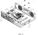
- FIG. 1I is a diagram depicting the reversible I/O apparatus 100 with the top cover 101 and the front bezel cover 103 removed with removal of motherboard sled/tray 114 and showing the I/O ports 110 to the motherboard 111a with a front orientation when the motherboard sled/tray 114 is removed from the housing 100a, according to an example embodiment.
- the motherboard 111a resides on a sled/tray 114 that is removable from a base 115 of the housing 100a of the reversible I/O apparatus 100.
- the sled 114 can then be orientated to have front-facing I/O peripheral ports 110 or to have the fan portion 112 front-facing.
- FIG. 1J is a diagram depicting the motherboard sled/tray 114 independent of the housing 100a, according to an example embodiment.
- the motherboard sled 114 is completely removable from the reversible I/O apparatus 100 for achieving a desired orientation for the I/O ports 110 (front-facing or rear-facing).
- the top of the sides of the sled 114 includes holes that permit the card for the power button 105 and LED indicators 106 to connect via cabling within the housing to the proper ports 110 when the reversible I/O apparatus 100 has the ports 110 oriented in a rear-facing configuration.
- the reversible I/O apparatus 100 is integrated within and part of a POS terminal.
- POS terminal's motherboard housing can have a reversible I/O port orientation depending on each installation need. This improves servicing and customer satisfaction while maximizing space utilization within a housing for the motherboard and hard drive(s) and without substantially impacting the overall size and dimensions of the housing itself.
- FIG. 2 is a diagram of a method 200 for reversing I/O for a reversible I/O apparatus, according to an example embodiment.
- the I/O reversible I/O apparatus is the I/O reversible apparatus 100 of FIGS. 1A-1J .
- the I/O reversible apparatus is part of and integrated within a POS terminal.
- a front bezel and a top cover is removed from a housing having a motherboard and a plurality of I/O peripheral ports.
- At 211 detaches cabling to a card for a power button and a status light indicator from a port on the motherboard.
- a hard drive tray having a hard drive is removed from a top of the sled (discussed below at 220) and associated cabling is removed from a port of the motherboard.
- the hard drive tray is re-oriented in a different position on the top of the sled ensuring the hard drive from the hard drive tray is accessible from the front of the housing when the front bezel is removed.
- a sled is removed out of the housing where the sled includes the motherboard.
- the sled is turned to orient I/O peripheral ports to face the front bezel or where the front bezel was removed from the housing.
- the sled is placed back into the housing.
- a cable is connected from a peripheral to one of the I/O peripheral ports and the cable is weaved in a recessed gap at a front-facing bottom of the housing.
- the cable is further weaved under a space of the housing created by legs on a bottom of the housing.
- the front bezel and top cover is attached back on the housing.
- FIG. 3 is a diagram of POS terminal 300 having the reversible I/O apparatus, according to an example embodiment.
- the POS terminal 300 includes a motherboard integrated within a reversible I/O apparatus 301 and at least one peripheral 302 coupled thereto.
- the peripherals 302 include one or more of: a magnetic card reader, a keyboard, a signature pad, a cash drawer, a monitor/display, a touchscreen, a scanner, a printer, a receipt printer, a disk drive, a network device, and the others.
- the reversible I/O apparatus 301 is the reversible I/O apparatus 100 of FIGS. 1A-1J .
- the reversible I/O apparatus 301 is the revisable I/O apparatus discussed above with reference to FIG. 2 .
- the motherboard integrated within the reversible I/O apparatus 301 is adapted to be oriented to a front of the housing for the motherboard where a power button and a status indicator are located.
- the I/O apparatus 301 is adapted to be removed from the housing.
- the I/O apparatus 301 is further adapted to be placed back in the housing with the I/O apparatus 301 facing a rear of the housing.
Landscapes
- Engineering & Computer Science (AREA)
- Theoretical Computer Science (AREA)
- Physics & Mathematics (AREA)
- General Physics & Mathematics (AREA)
- Computer Hardware Design (AREA)
- Power Engineering (AREA)
- Human Computer Interaction (AREA)
- General Engineering & Computer Science (AREA)
- Microelectronics & Electronic Packaging (AREA)
- Cash Registers Or Receiving Machines (AREA)
Abstract
Description
- Point-Of-Sale (POS) terminals are often comprised of: a motherboard, one or more hard drives, and a variety of peripheral ports to interface peripheral devices to the motherboard. The peripheral devices can include such things as: network ports (such as Ethernet), monitors/displays, keyboard, card readers, scanners, cash drawer, receipt printer, camera, PINpad, signature input device, and the like.
- The motherboard, hard drive(s), and peripheral ports are provided in a single housing and typically stowed under the cash drawer or somewhere in close proximity to the monitor and/or cash drawer.
- Conventionally, the motherboard is designed with a front facing power on and off button and Light Emitting Diode (LED) indicators providing a visual status of what state the motherboard is in, e.g., on, off, working on some activity, etc. The Input/Output (I/O) peripheral ports are located in the rear of the motherboard. This configuration is believed superior so as to hide cabling cords connecting peripherals to the I/O peripheral ports while providing easy front access to the power button and the LED indicators.
- However, in practice, the housing of the motherboard is usually placed on a shelf or in a cabinet with little available physical space to spare, such that removing the housing for service requires pulling the housing with attached cables entirely out of the cabinet or enclosure to access the I/O peripheral ports and associated cabling. In some situations, this requires substantial physical dexterity to hold the housing with one hand while trying to disconnect one or more cables or attach a new cable to the I/O peripheral ports with the remaining hand. Moreover, a POS terminal's motherboard housing can have many cables attached, such that trying to figure out what cable goes where after disconnecting the cables can be problematic.
- The time it takes to actually remove the housing from its enclosure or cabinet can also be more than a normal service operation (i.e., upgrading Random Access Memory (RAM), checking internal motherboard components, removing internal dust, etc.). Many retail stores can have hundreds of POS terminals, in integration trays that require annual preventive maintenance service. The time it takes a service engineer to just access the POS terminals for service is a significant percentage of total service time.
- In various embodiments, reversible I/O apparatuses for a POS terminal, a method of reversing I/O within an apparatus, and a POS terminal having the reversible I/O apparatus are provided.
- According to an embodiment, a reversible I/O apparatus is presented, comprising: a motherboard attached to a sled; and a housing encasing the sled. The sled is attached to the housing and oriented with Input/Output (I/O) peripheral ports oriented to a front of the housing with the power button and status indicator light.
- According to a first aspect of the present invention there is provided an apparatus, comprising: a motherboard attached to a sled; and a housing encasing the sled; wherein the sled is attached to the housing and oriented with Input/Output (I/O) peripheral ports oriented to a front of the housing with the power button and status indicator light.
- The sled is optionally configured to be removed from the housing and oriented to a rear of the housing opposite the power button and the status indicator light.
- Optionally, a front-facing bottom of the housing includes a gap between a front bezel of the housing and the front-facing bottom, the gap being configured to allow cables to run from the I/O ports to a rear of the housing.
- The apparatus optionally further includes legs attached to a bottom of the housing creating a space configured to allow the cables to run under the housing to the rear of the housing.
- The legs are optionally configured to be removed from the bottom of the housing when the sled is removed and the I/O peripheral ports are oriented to the rear of the housing.
- The apparatus optionally further includes a card slot in a front-side portion of the housing configured for interfacing the power button and the status indicator light.
- Optionally, the top sides of the sled include a hole configured to run an interface cable from the card to a specific I/O peripheral port in the rear of the housing when the sled is removed and the I/O peripheral ports are oriented to the rear of the housing.
- Optionally, the apparatus includes a hard drive port integrated into a tray, the tray being configured to be placed on top of the sled and under a top cover of the housing.
- Optionally, the tray is configured to be removed from the sled and oriented for access from the front of the housing when the I/O peripheral ports are oriented to the front and when the I/O peripheral ports are oriented to a rear of the housing.
- Optionally, the housing includes a removable bezel from the front of the housing having a single knob to remove the bezel from the housing and to lock the bezel to the housing.
- Optionally, an inside of the bezel includes a reinforced steel plate configured to provide rigidity against cables connected to the I/O peripheral ports.
- According to a second aspect of the present invention there is provided a method comprising: detaching a front bezel and a top cover of a housing; removing a sled having a motherboard out of the housing; turning the sled to orient Input/Output (I/O) peripheral ports to face the front bezel; placing the sled back into the housing; and attaching the front bezel and top cover back on the housing.
- Optionally, detaching the front bezel further includes detaching cabling to a card for a power button and a status light indicator from a port on the motherboard.
- Optionally, detaching the front bezel further includes removing a hard drive tray from a top of the sled and associated cabling from a port of the motherboard.
- Optionally, detaching the front bezel further includes re-orienting the hard drive tray in a different position on the top of the sled ensuing the hard drive from the hard drive tray is accessible from the front of the housing when the front bezel is removed.
- Optionally, placing the sled back into the housing further includes connecting a cable from a peripheral to one of the I/O peripheral ports and weaving the cable in a recessed gap at a front-facing bottom of the housing.
- Optionally, connecting the cable from a peripheral to one of the I/O peripheral ports further includes weaving the cable under a space of the housing created by legs on a bottom of the housing.
- According to a third aspect of the present invention there is provided a Point-Of-Sale (POS) terminal, comprising: at least one peripheral; and a motherboard integrated within a reversible Input/Output (I/O) apparatus that is configured to be oriented to a front of a housing for the motherboard where a power button and a status indicator are located.
- Optionally, the I/O apparatus is configured to be removed from the housing.
- Optionally, the I/O apparatus is configured to be placed back in the housing with the I/O apparatus facing a rear of the housing.
- These and other aspects of the present invention will become apparent from the following specific description, given by way of example, with reference to the accompanying drawings, in which:
-
FIG. 1A is a diagram depicting a covered reversible I/O apparatus oriented to depict the front, top, and one side of the reversible I/O apparatus, according to an example embodiment; -
FIG. 1B is a diagram depicting the reversible I/O apparatus housing with the front bezel cover removed and no motherboard installed in the housing, according to an example embodiment; -
FIG. 1C is a diagram depicting the reversible I/O apparatus with the top cover and front bezel cover removed with an installed motherboard showing the I/O ports to the motherboard with a front orientation, according to an example embodiment; -
FIG. 1D is a diagram depicting the reversible I/O apparatus with the front bezel cover removed with an installed motherboard showing the I/O ports to the motherboard with a front orientation, according to an example embodiment; -
FIG. 1E is a diagram depicting the reversible I/O apparatus with the front bezel cover removed with an installed motherboard showing the fan portion of the motherboard with a front orientation, according to an example embodiment; -
FIG. 1F is a diagram depicting the reversible I/O apparatus with the top cover and the front bezel cover removed with an installed motherboard showing the I/O ports to the motherboard with a front orientation and showing a stacked installed orientation of the hard drive, according to an example embodiment; -
FIG. 1G is a diagram depicting the reversible I/O apparatus with the top cover and the front bezel cover removed with an installed motherboard showing the fan portion of the motherboard with a front orientation and showing a stacked installed orientation of the hard drive, according to an example embodiment; -
FIG. 1H is a diagram depicting the reversible I/O apparatus with the top cover and the front bezel cover removed with an installed motherboard showing the I/O ports to the motherboard with a front orientation and showing removal of the hard drive tray, according to an example embodiment; -
FIG. 1I is a diagram depicting the reversible I/O apparatus with the top cover and the front bezel cover removed with removal of motherboard sled/tray and showing the I/O ports to the motherboard with a front orientation when the motherboard sled/tray is removed from the housing, according to an example embodiment; -
FIG. 1J is a diagram depicting the motherboard sled/tray independent of the housing, according to an example embodiment; -
FIG. 2 is a diagram of a method for reversing I/O for a reversible I/O apparatus, according to an example embodiment; and -
FIG. 3 is a diagram of POS terminal having the reversible I/O apparatus, according to an example embodiment. - Reference is first made to
FIG. 1A , which is a diagram depicting a covered reversible I/O apparatus 100 oriented to depict the front, top, and one side of the reversible I/O apparatus, according to an example embodiment. It is to be noted that the configuration is shown schematically in greatly simplified form, with only those components relevant to understanding of this embodiment being illustrated. - The reversible I/
O apparatus 100 depicted inFIG 1A shows atop cover 101, one or twosides 102, afront bezel cover 103, aturn knob 104 to remove (unlock) thefront bezel cover 103 from thehousing 100a (best seen inFIG 1I ) of theapparatus 100 or to close and lock thefront bezel cover 103 onto the housing of theapparatus 100, apower button 105, LEDstatus indicator lights 106, and legs 107 (two of fourlegs 107 shown inFIG. 1A . -
FIG. 1A illustrates a major part of a POS terminal (without attached peripherals: card reader, keyboard, display, receipt printer, signature pad, scanner, cash drawer, PIN pad, etc.) as it is viewed from its front user-facing orientation. This is the orientation that the reversible I/O apparatus 100 is in when accessed (via the power button) by an operator to power the POS terminal on and off. This is also the orientation that a service engineer would encounter when first accessing the reversible I/O apparatus 100 for service in a cabinet/enclosure. The reversible I/O apparatus 100, when connected to I/O peripherals, can function as a POS terminal. -
FIG. 1B is a diagram depicting the reversible I/O apparatus housing 100a with thefront bezel cover 103 removed and no motherboard installed in thehousing 100a, according to an example embodiment. - In
FIG. 1B , theturn knob 104 has been turned counter clockwise (can also be clockwise) to unlock thefront bezel cover 103 from thehousing 100a exposing the inner cabinet of thehousing 100a (which is empty inFIG. 1B for illustrative purposes). - In an embodiment, the
bezel 103 includes a reinforced steel plate on an inside portion of the bezel 103 (the portion facing the I/O peripheral ports 110 (FIG 1D ) when front-facing). This provides structural rigidity to thebezel 103 when pushed against cabling connected to the I/O peripheral ports 110). - The
front bezel cover 103 includes slots through which thepower button 105 andLED status indicators 106 protrude for user access and user visibility. Thepower button 105 andLED status indicators 106 are integrated into a modular card on a front lip of the front of thehousing 100a and interfaced to the motherboard via cabling. As will be discussed more completely herein and below thepower button 105 and theLED status indicators 106 remain fixed in a front-facing orientation within thehousing 100a irrespective of whether the I/Operipheral ports 110 are front-facing or rear-facing within thehousing 100a. - The
housing 100a also shows a recessedcurved portion 109 of the front-facing bottom of thehousing 100a along withextended portion 108 of the front-facing bottom of thehousing 100a. This creates a gap between the bottom of thefront bezel 103 and the front-facing bottom of the housing when thebezel 103 is in a closed position and locked onto thehousing 100a. In an embodiment, the gap is between 25 and 50 mm (1-2 inches) and forms a trapezoid shaped hole when the housing is assembled as shown inFIG. 1A (the trapezoid shaped hole is not visible inFIG. 1A ). - The gap permits cabling to run underneath the housing when the reversible I/
O apparatus 100 is oriented with the I/Operipheral ports 110 in a front-facing orientation/configuration. Thelegs 107 as shown inFIG. 1A also create a space underneath the housing for the cabling to run back to the rear of the reversible I/O apparatus 100 for connection to the peripheral devices. In an embodiment, the height of thelegs 107 creates approximately a 25 to 38 mm (1 to 1.5 inch) gap under the reversible I/O apparatus 100. In an embodiment, thelegs 107 are removable, if desired, to decrease the height of the reversible I/O apparatus 100 (this would be when the I/O peripheral ports are in a rear-facing orientation/configuration). - The directional arrow in
FIG. 1B (and subsequent figures) is intended to illustrate the recession and gap created by the offset of 108 and 109 and manufactured into the base of the bottom of thehousing 100a. -
FIG. 1C is a diagram depicting the reversible I/O apparatus 100 with thetop cover 101 andfront bezel cover 103 removed with an installed motherboard (shown generally as 111a, but best seen inFIG 1J ) showing the I/O ports 110 to themotherboard 111a with a front orientation, according to an example embodiment. - In
FIG. 1C , themotherboard 111a is oriented within the reversible I/O apparatus 100 such that the I/Operipheral ports 110 are front-facing. - In this configuration, all the I/O
peripheral ports 110 are accessible to a server engineer by removing thefront bezel 103 without removing the entire reversible I/O apparatus 100 from its enclosure and possibly disconnecting cabling to the I/Operipheral ports 110 in the process. When cabling is connected, it can be removed if needed and laid on the surface that the reversible I/O apparatus 100 rests in line with the specific I/O ports 110 to which the removed cabling was originally connected. This improves servicing of the reversible I/O apparatus 100 and can be done within the enclosure where the reversible I/O apparatus 100 is natively stowed. The cabling runs under the reversible I/O apparatus 100 in the space created by thelegs 107 and behind thebezel 103 in the gap created by recessedportion 109. -
FIG. 1D is a diagram depicting the reversible I/O apparatus 100 with thefront bezel cover 103 removed with an installedmotherboard 111a showing the I/O ports to themotherboard 111a with a front orientation, according to an example embodiment. -
FIG. 1D shows the front-facing I/Operipheral port 110 orientation with thetop cover 101 installed on the reversible I/O apparatus 100. -
FIG. 1E is a diagram depicting the reversible I/O apparatus 100 with thefront bezel cover 103 removed with an installedmotherboard 111a showing thefan portion 112 of themotherboard 111a with a front orientation, according to an example embodiment. -
FIG. 1E shows thefan portion 112 of themotherboard 111a in a front-facing orientation. Here, the I/Operipheral ports 110 are in a rear-facing orientation (a traditional orientation). -
FIG. 1F is a diagram depicting the reversible I/O apparatus 100 with thetop cover 101 and thefront bezel cover 103 removed with an installedmotherboard 111a showing the I/O ports 110 to themotherboard 111a with a front orientation and showing a stacked installed orientation of the hard drive, according to an example embodiment. -
FIG. 1 F shows the front-facing I/Operipheral ports 110 of themotherboard 111a in a front-facing orientation with the installedhard drive 111. -
FIG. 1 G is a diagram depicting the reversible I/O apparatus 100 with thetop cover 101 and thefront bezel cover 103 removed with an installedmotherboard 111a showing thefan portion 112 of themotherboard 111a with a front orientation and showing a stacked installed orientation of thehard drive 111, according to an example embodiment. -
FIG. 1G shows thefan portion 112 of themotherboard 111a in a front-facing orientation with the installedhard drive 111. - It is noted that in either orientation fan-
portion 112 front-facing or I/Operipheral ports 110 front facing, thehard drive 111 is always front facing for ease of access when thebezel 103 is removed from the reversible I/O apparatus 100. -
FIG. 1 H is a diagram depicting the reversible I/O apparatus 100 with thetop cover 101 and thefront bezel cover 103 removed with an installedmotherboard 111a showing the I/O ports 110 to themotherboard 111a with a front orientation and showing removal of thehard drive tray 113, according to an example embodiment. -
FIG. 1H illustrates that thehard drive 111 includes itsown tray 113 that is removable from the rest of the reversible I/O apparatus 100 and that stacks on top of themotherboard 111a. This permits thehard drive 111 to be always front-facing regardless of whether the reversible I/O apparatus 100 is in an I/Operipheral port 110 front-facing orientation or in afan portion 112 front-facing orientation within the reversible I/O apparatus 100. Cabling permits the port on the hard drive to connect to the proper port on the motherboard underneath theremovable tray 113. Theremovable tray 113 is adapted to be removed and repositioned to ensure thehard drive 111 is always front-facing. -
FIG. 1I is a diagram depicting the reversible I/O apparatus 100 with thetop cover 101 and thefront bezel cover 103 removed with removal of motherboard sled/tray 114 and showing the I/O ports 110 to themotherboard 111a with a front orientation when the motherboard sled/tray 114 is removed from thehousing 100a, according to an example embodiment. - In
FIG. 1I themotherboard 111a resides on a sled/tray 114 that is removable from abase 115 of thehousing 100a of the reversible I/O apparatus 100. Thesled 114 can then be orientated to have front-facing I/Operipheral ports 110 or to have thefan portion 112 front-facing. -
FIG. 1J is a diagram depicting the motherboard sled/tray 114 independent of thehousing 100a, according to an example embodiment. - The
motherboard sled 114 is completely removable from the reversible I/O apparatus 100 for achieving a desired orientation for the I/O ports 110 (front-facing or rear-facing). The top of the sides of thesled 114 includes holes that permit the card for thepower button 105 andLED indicators 106 to connect via cabling within the housing to theproper ports 110 when the reversible I/O apparatus 100 has theports 110 oriented in a rear-facing configuration. - In an embodiment, the reversible I/
O apparatus 100 is integrated within and part of a POS terminal. - With the I/O
peripheral ports 110 facing forward, accessing the I/O ports 110 for additional cables, removal or servicing existing cabling is much easier. When the main part of the POS terminal (motherboard housing) is removed from the cabinet or enclosure, the cables are facing the service engineer or customer. Therefore, there is no need to access the rear of the cabinet or enclosure. Once the cables are disconnected, they are simply laid down in place. There is no need to reposition the cable nor add or remove cable slack. The terminal slides out of the enclosure or cabinet over the cables. Thus, the time required to remove the terminal from the enclosure is much less than if the I/O ports 110 was rear-facing. Also, the risk of damaging the cables or connectors on the motherboard is significantly minimized from a conventional rear-facing I/O orientation. There is no need to pull the terminal with multiple connected cables and stress the motherboard connectors, such as when the I/O is in a rear-facing orientation. Risk of dropping the terminal is minimized as well since both hands can now be used to remove the terminal without trying to use one hand to disconnect cables in the rear of the terminal. - One now appreciates how a POS terminal's motherboard housing can have a reversible I/O port orientation depending on each installation need. This improves servicing and customer satisfaction while maximizing space utilization within a housing for the motherboard and hard drive(s) and without substantially impacting the overall size and dimensions of the housing itself.
- These and other embodiments are now discussed with reference to
FIGS. 2-3 . -
FIG. 2 is a diagram of amethod 200 for reversing I/O for a reversible I/O apparatus, according to an example embodiment. - In an embodiment, the I/O reversible I/O apparatus is the I/O
reversible apparatus 100 ofFIGS. 1A-1J . - In an embodiment, the I/O reversible apparatus is part of and integrated within a POS terminal.
- At 210, a front bezel and a top cover is removed from a housing having a motherboard and a plurality of I/O peripheral ports.
- In an embodiment, at 211, detaches cabling to a card for a power button and a status light indicator from a port on the motherboard.
- In an embodiment, at 212, a hard drive tray having a hard drive is removed from a top of the sled (discussed below at 220) and associated cabling is removed from a port of the motherboard.
- In an embodiment of 212 and at 213, the hard drive tray is re-oriented in a different position on the top of the sled ensuring the hard drive from the hard drive tray is accessible from the front of the housing when the front bezel is removed.
- At 220, a sled is removed out of the housing where the sled includes the motherboard.
- At 230, the sled is turned to orient I/O peripheral ports to face the front bezel or where the front bezel was removed from the housing.
- At 240, the sled is placed back into the housing.
- In an embodiment, at 241, a cable is connected from a peripheral to one of the I/O peripheral ports and the cable is weaved in a recessed gap at a front-facing bottom of the housing.
- In an embodiment of 241 and at 242, the cable is further weaved under a space of the housing created by legs on a bottom of the housing.
- At 250, the front bezel and top cover is attached back on the housing.
-
FIG. 3 is a diagram of POS terminal 300 having the reversible I/O apparatus, according to an example embodiment. - The
POS terminal 300 includes a motherboard integrated within a reversible I/O apparatus 301 and at least one peripheral 302 coupled thereto. - In an embodiment, the
peripherals 302 include one or more of: a magnetic card reader, a keyboard, a signature pad, a cash drawer, a monitor/display, a touchscreen, a scanner, a printer, a receipt printer, a disk drive, a network device, and the others. - In an embodiment, the reversible I/O apparatus 301 is the reversible I/
O apparatus 100 ofFIGS. 1A-1J . - In an embodiment, the reversible I/O apparatus 301 is the revisable I/O apparatus discussed above with reference to
FIG. 2 . - The motherboard integrated within the reversible I/O apparatus 301 is adapted to be oriented to a front of the housing for the motherboard where a power button and a status indicator are located.
- In an embodiment, the I/O apparatus 301 is adapted to be removed from the housing.
- In an embodiment of the latter embodiment, the I/O apparatus 301 is further adapted to be placed back in the housing with the I/O apparatus 301 facing a rear of the housing.
- The above description is illustrative, and not restrictive. Many other embodiments will be apparent to those of skill in the art upon reviewing the above description. The scope of embodiments should therefore be determined with reference to the appended claims, along with the full scope of equivalents to which such claims are entitled.
- In the foregoing description of the embodiments, various features are grouped together in a single embodiment for the purpose of streamlining the disclosure. This method of disclosure is not to be interpreted as reflecting that the claimed embodiments have more features than are expressly recited in each claim. Rather, as the following claims reflect, inventive subject matter lies in less than all features of a single disclosed embodiment.
Claims (15)
- An apparatus (100 or 301) comprising:a motherboard (111a) attached to a sled (114); anda housing (100a) encasing the sled (114);wherein the sled (114) is attached to the housing (100a) and oriented with I/O peripheral ports (110) oriented to a front of the housing (100a) with a power button (105) and a status indicator light (106).
- The apparatus of claim 1, wherein the sled (114) is adapted to be removed from the housing (100a) and oriented to a rear of the housing (100a) opposite the power button (105) and the status indicator light (106).
- The apparatus of either claim 1 or 2, wherein a front-facing bottom of the housing (100a) includes a gap between a front bezel (103) of the housing (100a) and the front-facing bottom (108,109), the gap being configured to allow cables to run from the I/O peripheral ports (110) to a rear of the housing (100a).
- The apparatus of claim 3, wherein the apparatus further includes legs (107) attached to a bottom of the housing (100a) creating a space adapted to allow the cables to run under the housing (100a) to the rear of the housing (100a).
- The apparatus of claim 4, wherein the legs (107) are configured to be removed from the bottom of the housing (100a) when the sled (114) is removed and the I/O peripheral ports (110) are oriented to the rear of the housing (100a).
- The apparatus of any preceding claim, wherein the apparatus further includes a card slot in a front-side portion of the housing (100a) configured for interfacing the power button (105) and the status indicator light (106).
- The apparatus of claim 6, wherein top sides of the sled (114) include a hole arranged to run an interface cable from the card to a specific I/O peripheral port (110) in the rear of the housing (100a) when the sled (114) is removed and the I/O peripheral ports (110) are oriented to the rear of the housing (100a).
- The apparatus of any preceding claim, wherein the apparatus includes a hard drive (111) integrated into a tray (113), the tray (113) being configured to be placed on top of the sled (114) and under a top cover (101) of the housing (100a).
- The apparatus of claim 8, wherein the tray (113) is adapted to be removed from the sled (114) and oriented for access from the front of the housing (100a) when the I/O peripheral ports (110) are oriented to the front and when the I/O peripheral ports (110) are oriented to the rear of the housing (100a).
- The apparatus of any preceding claim, wherein the housing (100a) includes a front bezel (103) removable from the front of the housing (100a) and having a single knob (104) to remove the front bezel (103) from the housing (100a) and to lock the front bezel (103) to the housing (100a).
- The apparatus of any preceding claim, wherein an inside of the front bezel (103) includes a reinforced steel plate arranged to provide rigidity against cables connected to the I/O peripheral ports (110).
- A Point-Of-Sale terminal (300), comprising:apparatus (100) according to any of claims 1 to 11; andat least one peripheral coupled to the apparatus (100).
- A method comprising:detaching a front bezel (103) and a top cover (101) of a housing (100a);removing a sled (114) having a motherboard (111 a) out of the housing (100a);turning the sled (114) to orient I/O peripheral ports (110) to face the front bezel (103);placing the sled (114) back into the housing (100a); andattaching the front bezel (103) and top cover (101) back on the housing (100a).
- The method of claim 13, wherein detaching the front bezel (103) further includes detaching cabling to a card for a power button (105) and a status light indicator (106) from a port on the motherboard (111a), or removing a hard drive tray (113) from a top of the sled (114) and associated cabling from a port of the motherboard (111a) and re-orienting the hard drive tray (113) in a different position on the top of the sled (114) to ensure that a hard drive (111) mounted in the hard drive tray (113) is accessible from the front of the housing (100a) when the front bezel (103) is removed.
- The method of claim 13 or 14, wherein placing the sled (114) back into the housing (100a) further includes connecting a cable from a peripheral to one of the I/O peripheral ports (110) and weaving the cable under a space of the housing (100a) created by legs (107) on a bottom of the housing (100a) at a front-facing bottom of the housing (100a).
Applications Claiming Priority (1)
| Application Number | Priority Date | Filing Date | Title |
|---|---|---|---|
| US14/996,595 US9575517B1 (en) | 2016-01-15 | 2016-01-15 | Reversible input/output (I/O) |
Publications (2)
| Publication Number | Publication Date |
|---|---|
| EP3193234A1 true EP3193234A1 (en) | 2017-07-19 |
| EP3193234B1 EP3193234B1 (en) | 2022-11-09 |
Family
ID=57838183
Family Applications (1)
| Application Number | Title | Priority Date | Filing Date |
|---|---|---|---|
| EP17151097.7A Active EP3193234B1 (en) | 2016-01-15 | 2017-01-11 | Reversible input/output (i/o) |
Country Status (2)
| Country | Link |
|---|---|
| US (1) | US9575517B1 (en) |
| EP (1) | EP3193234B1 (en) |
Families Citing this family (5)
| Publication number | Priority date | Publication date | Assignee | Title |
|---|---|---|---|---|
| US20170353014A1 (en) * | 2016-06-07 | 2017-12-07 | Belden Canada Inc. | Rackmount case for the accommodation of optical equipment |
| DE102018009011A1 (en) * | 2018-11-16 | 2020-05-20 | Keba Ag | Lottery or cash register terminal |
| USD933666S1 (en) * | 2019-05-24 | 2021-10-19 | Axis Ab | Data processing device |
| USD932494S1 (en) * | 2019-05-24 | 2021-10-05 | Axis Ab | Data processing device |
| US11525590B2 (en) * | 2021-02-01 | 2022-12-13 | Dell Products L.P. | Bezel with air filtration and cable management for an information handling system |
Citations (5)
| Publication number | Priority date | Publication date | Assignee | Title |
|---|---|---|---|---|
| US6282084B1 (en) * | 1999-02-22 | 2001-08-28 | International Business Machines Corporation | Transportable support apparatus for portable computers |
| US20030043545A1 (en) * | 2001-08-31 | 2003-03-06 | Sam Ivey | Control panel assembly |
| US20090161322A1 (en) * | 2007-12-21 | 2009-06-25 | Hughes Robert M | Front access enclosure |
| US7639505B2 (en) * | 2005-07-29 | 2009-12-29 | Hong Fu Jin Precision Industry (Shenzhen) Co., Ltd. | Computer enclosure |
| US20130021756A1 (en) * | 2011-07-21 | 2013-01-24 | Hon Hai Precision Industry Co., Ltd. | Data center with cable management structure |
Family Cites Families (17)
| Publication number | Priority date | Publication date | Assignee | Title |
|---|---|---|---|---|
| US4918572A (en) * | 1988-12-27 | 1990-04-17 | Motorola Computer X, Inc. | Modular electronic package |
| US5136468A (en) * | 1991-03-15 | 1992-08-04 | Amkly Systems, Inc. | Modular computer chassis |
| US5311397A (en) * | 1992-08-06 | 1994-05-10 | Logistics Management Inc. | Computer with modules readily replaceable by unskilled personnel |
| US5600538A (en) * | 1994-07-08 | 1997-02-04 | Apple Computer, Inc. | Personal computer and housing structure having circuit board removable horizontally and sub-chassis removable from the top thereof |
| US5774330A (en) * | 1995-05-01 | 1998-06-30 | Apple Computer, Inc. | Apparatus for supporting operational components of a personal computer |
| US5717575A (en) * | 1995-08-09 | 1998-02-10 | Digital Equipment Corporation | Board mounting system with self guiding interengagement |
| US5764480A (en) * | 1996-09-23 | 1998-06-09 | International Business Machines Corporation | Computer system having a latching drive housing which pivots on hinge pins between an open position wherein a DASD is accessible and a closed position wherein the DASD is not accessible |
| US6003008A (en) * | 1998-03-20 | 1999-12-14 | Skyteller L.L.C. | Point of sale device |
| US6053410A (en) * | 1998-04-30 | 2000-04-25 | Ncr Corporation | Retail terminal having a plurality of base assemblies each of which includes a separate power supply and associate method |
| US6771516B1 (en) * | 1999-12-27 | 2004-08-03 | Micron Technology, Inc. | Method and apparatus for fastening circuit boards to computer chassis |
| EP1557074A4 (en) * | 2002-10-22 | 2010-01-13 | Sullivan Jason | Robust customizable computer processing system |
| TWM245480U (en) * | 2003-10-14 | 2004-10-01 | Shuttle Inc | Improved housing of computer host |
| JP4541086B2 (en) * | 2004-09-27 | 2010-09-08 | 東芝テック株式会社 | Controller for merchandise sales data processing apparatus and method for sharing parts used for the same |
| CN2791729Y (en) * | 2005-04-09 | 2006-06-28 | 鸿富锦精密工业(深圳)有限公司 | Computer housing |
| US7566104B2 (en) * | 2006-05-08 | 2009-07-28 | Lian Li Industrial Co., Ltd. | Bi-directional side emplacing computer casing |
| US20090267465A1 (en) * | 2008-04-25 | 2009-10-29 | King Young Technology Co., Ltd. | Microcomputer case |
| TWM351389U (en) * | 2008-09-01 | 2009-02-21 | Aopen Inc | Computer enclosure and computer |
-
2016
- 2016-01-15 US US14/996,595 patent/US9575517B1/en active Active
-
2017
- 2017-01-11 EP EP17151097.7A patent/EP3193234B1/en active Active
Patent Citations (5)
| Publication number | Priority date | Publication date | Assignee | Title |
|---|---|---|---|---|
| US6282084B1 (en) * | 1999-02-22 | 2001-08-28 | International Business Machines Corporation | Transportable support apparatus for portable computers |
| US20030043545A1 (en) * | 2001-08-31 | 2003-03-06 | Sam Ivey | Control panel assembly |
| US7639505B2 (en) * | 2005-07-29 | 2009-12-29 | Hong Fu Jin Precision Industry (Shenzhen) Co., Ltd. | Computer enclosure |
| US20090161322A1 (en) * | 2007-12-21 | 2009-06-25 | Hughes Robert M | Front access enclosure |
| US20130021756A1 (en) * | 2011-07-21 | 2013-01-24 | Hon Hai Precision Industry Co., Ltd. | Data center with cable management structure |
Also Published As
| Publication number | Publication date |
|---|---|
| EP3193234B1 (en) | 2022-11-09 |
| US9575517B1 (en) | 2017-02-21 |
Similar Documents
| Publication | Publication Date | Title |
|---|---|---|
| EP3193234B1 (en) | Reversible input/output (i/o) | |
| US6462670B1 (en) | Server system having front and rear identification | |
| US9999161B2 (en) | Reversible fan assembly | |
| US6778381B1 (en) | Retractable display module | |
| US6407933B1 (en) | Cable management system for use with rack mounted devices | |
| US6556438B1 (en) | Dense packaging and cooling system for use with a server or other processor-based device | |
| US8161391B2 (en) | On-board input and management device for a computing system | |
| US6956745B2 (en) | Handling system for use with a blade in a blade server system | |
| US5896273A (en) | Modular computer chassis interchangeable between stand alone and rack mounted states | |
| US9326415B2 (en) | Chassis for storage devices | |
| US6741463B1 (en) | Rack mountable docking station | |
| US10736228B2 (en) | Removeable drive-plane apparatus, system, and method | |
| CN202025265U (en) | Server case | |
| US9943004B2 (en) | Positive pressure-applying latch mechanism | |
| CN113849042B (en) | Compute node with chassis with front-mounted GPU tray | |
| GB2410839A (en) | Electronic system with a simplified enclosure | |
| WO2009075953A2 (en) | Modular power supply for computer servers | |
| US7379303B2 (en) | Computing device module | |
| WO2010080150A1 (en) | Computer including hot-pluggable disk storage drives that are mounted in an in-line arrangement | |
| US6206285B1 (en) | Peripheral assembly kit for the workstation of a goods invoicing system | |
| US7576977B2 (en) | Shoulder screw and handle drive mounting system | |
| EP3729922A1 (en) | System and method for connecting at least one electronic card to a printed circuit board | |
| US6754084B1 (en) | System for mounting PCI cards | |
| TW201616942A (en) | Support member | |
| EP3001160A1 (en) | Attached printer for a weighing scale |
Legal Events
| Date | Code | Title | Description |
|---|---|---|---|
| PUAI | Public reference made under article 153(3) epc to a published international application that has entered the european phase |
Free format text: ORIGINAL CODE: 0009012 |
|
| STAA | Information on the status of an ep patent application or granted ep patent |
Free format text: STATUS: THE APPLICATION HAS BEEN PUBLISHED |
|
| AK | Designated contracting states |
Kind code of ref document: A1 Designated state(s): AL AT BE BG CH CY CZ DE DK EE ES FI FR GB GR HR HU IE IS IT LI LT LU LV MC MK MT NL NO PL PT RO RS SE SI SK SM TR |
|
| AX | Request for extension of the european patent |
Extension state: BA ME |
|
| RIN1 | Information on inventor provided before grant (corrected) |
Inventor name: CODERA, ADONIS Inventor name: ABING, LUCKY Inventor name: EGAN, GREGORY Inventor name: CHAN, SENG Inventor name: KLEPPINGER, MICHAEL |
|
| STAA | Information on the status of an ep patent application or granted ep patent |
Free format text: STATUS: REQUEST FOR EXAMINATION WAS MADE |
|
| 17P | Request for examination filed |
Effective date: 20180119 |
|
| RBV | Designated contracting states (corrected) |
Designated state(s): AL AT BE BG CH CY CZ DE DK EE ES FI FR GB GR HR HU IE IS IT LI LT LU LV MC MK MT NL NO PL PT RO RS SE SI SK SM TR |
|
| STAA | Information on the status of an ep patent application or granted ep patent |
Free format text: STATUS: EXAMINATION IS IN PROGRESS |
|
| RAP1 | Party data changed (applicant data changed or rights of an application transferred) |
Owner name: NCR CORPORATION |
|
| 17Q | First examination report despatched |
Effective date: 20180502 |
|
| RIC1 | Information provided on ipc code assigned before grant |
Ipc: H05K 7/14 20060101ALI20220614BHEP Ipc: H05K 5/02 20060101ALI20220614BHEP Ipc: G07G 1/12 20060101ALI20220614BHEP Ipc: G07G 1/00 20060101ALI20220614BHEP Ipc: G06F 1/18 20060101AFI20220614BHEP |
|
| GRAP | Despatch of communication of intention to grant a patent |
Free format text: ORIGINAL CODE: EPIDOSNIGR1 |
|
| STAA | Information on the status of an ep patent application or granted ep patent |
Free format text: STATUS: GRANT OF PATENT IS INTENDED |
|
| INTG | Intention to grant announced |
Effective date: 20220803 |
|
| GRAS | Grant fee paid |
Free format text: ORIGINAL CODE: EPIDOSNIGR3 |
|
| GRAA | (expected) grant |
Free format text: ORIGINAL CODE: 0009210 |
|
| STAA | Information on the status of an ep patent application or granted ep patent |
Free format text: STATUS: THE PATENT HAS BEEN GRANTED |
|
| AK | Designated contracting states |
Kind code of ref document: B1 Designated state(s): AL AT BE BG CH CY CZ DE DK EE ES FI FR GB GR HR HU IE IS IT LI LT LU LV MC MK MT NL NO PL PT RO RS SE SI SK SM TR |
|
| REG | Reference to a national code |
Ref country code: GB Ref legal event code: FG4D |
|
| REG | Reference to a national code |
Ref country code: CH Ref legal event code: EP Ref country code: AT Ref legal event code: REF Ref document number: 1530797 Country of ref document: AT Kind code of ref document: T Effective date: 20221115 |
|
| REG | Reference to a national code |
Ref country code: DE Ref legal event code: R096 Ref document number: 602017063453 Country of ref document: DE |
|
| REG | Reference to a national code |
Ref country code: IE Ref legal event code: FG4D |
|
| REG | Reference to a national code |
Ref country code: DE Ref legal event code: R084 Ref document number: 602017063453 Country of ref document: DE |
|
| REG | Reference to a national code |
Ref country code: GB Ref legal event code: 746 Effective date: 20221122 |
|
| REG | Reference to a national code |
Ref country code: LT Ref legal event code: MG9D |
|
| REG | Reference to a national code |
Ref country code: NL Ref legal event code: MP Effective date: 20221109 |
|
| REG | Reference to a national code |
Ref country code: AT Ref legal event code: MK05 Ref document number: 1530797 Country of ref document: AT Kind code of ref document: T Effective date: 20221109 |
|
| PG25 | Lapsed in a contracting state [announced via postgrant information from national office to epo] |
Ref country code: SE Free format text: LAPSE BECAUSE OF FAILURE TO SUBMIT A TRANSLATION OF THE DESCRIPTION OR TO PAY THE FEE WITHIN THE PRESCRIBED TIME-LIMIT Effective date: 20221109 Ref country code: PT Free format text: LAPSE BECAUSE OF FAILURE TO SUBMIT A TRANSLATION OF THE DESCRIPTION OR TO PAY THE FEE WITHIN THE PRESCRIBED TIME-LIMIT Effective date: 20230309 Ref country code: NO Free format text: LAPSE BECAUSE OF FAILURE TO SUBMIT A TRANSLATION OF THE DESCRIPTION OR TO PAY THE FEE WITHIN THE PRESCRIBED TIME-LIMIT Effective date: 20230209 Ref country code: LT Free format text: LAPSE BECAUSE OF FAILURE TO SUBMIT A TRANSLATION OF THE DESCRIPTION OR TO PAY THE FEE WITHIN THE PRESCRIBED TIME-LIMIT Effective date: 20221109 Ref country code: FI Free format text: LAPSE BECAUSE OF FAILURE TO SUBMIT A TRANSLATION OF THE DESCRIPTION OR TO PAY THE FEE WITHIN THE PRESCRIBED TIME-LIMIT Effective date: 20221109 Ref country code: ES Free format text: LAPSE BECAUSE OF FAILURE TO SUBMIT A TRANSLATION OF THE DESCRIPTION OR TO PAY THE FEE WITHIN THE PRESCRIBED TIME-LIMIT Effective date: 20221109 Ref country code: AT Free format text: LAPSE BECAUSE OF FAILURE TO SUBMIT A TRANSLATION OF THE DESCRIPTION OR TO PAY THE FEE WITHIN THE PRESCRIBED TIME-LIMIT Effective date: 20221109 |
|
| PG25 | Lapsed in a contracting state [announced via postgrant information from national office to epo] |
Ref country code: RS Free format text: LAPSE BECAUSE OF FAILURE TO SUBMIT A TRANSLATION OF THE DESCRIPTION OR TO PAY THE FEE WITHIN THE PRESCRIBED TIME-LIMIT Effective date: 20221109 Ref country code: PL Free format text: LAPSE BECAUSE OF FAILURE TO SUBMIT A TRANSLATION OF THE DESCRIPTION OR TO PAY THE FEE WITHIN THE PRESCRIBED TIME-LIMIT Effective date: 20221109 Ref country code: LV Free format text: LAPSE BECAUSE OF FAILURE TO SUBMIT A TRANSLATION OF THE DESCRIPTION OR TO PAY THE FEE WITHIN THE PRESCRIBED TIME-LIMIT Effective date: 20221109 Ref country code: IS Free format text: LAPSE BECAUSE OF FAILURE TO SUBMIT A TRANSLATION OF THE DESCRIPTION OR TO PAY THE FEE WITHIN THE PRESCRIBED TIME-LIMIT Effective date: 20230309 Ref country code: HR Free format text: LAPSE BECAUSE OF FAILURE TO SUBMIT A TRANSLATION OF THE DESCRIPTION OR TO PAY THE FEE WITHIN THE PRESCRIBED TIME-LIMIT Effective date: 20221109 Ref country code: GR Free format text: LAPSE BECAUSE OF FAILURE TO SUBMIT A TRANSLATION OF THE DESCRIPTION OR TO PAY THE FEE WITHIN THE PRESCRIBED TIME-LIMIT Effective date: 20230210 |
|
| P01 | Opt-out of the competence of the unified patent court (upc) registered |
Effective date: 20230505 |
|
| PG25 | Lapsed in a contracting state [announced via postgrant information from national office to epo] |
Ref country code: NL Free format text: LAPSE BECAUSE OF FAILURE TO SUBMIT A TRANSLATION OF THE DESCRIPTION OR TO PAY THE FEE WITHIN THE PRESCRIBED TIME-LIMIT Effective date: 20221109 |
|
| PG25 | Lapsed in a contracting state [announced via postgrant information from national office to epo] |
Ref country code: SM Free format text: LAPSE BECAUSE OF FAILURE TO SUBMIT A TRANSLATION OF THE DESCRIPTION OR TO PAY THE FEE WITHIN THE PRESCRIBED TIME-LIMIT Effective date: 20221109 Ref country code: RO Free format text: LAPSE BECAUSE OF FAILURE TO SUBMIT A TRANSLATION OF THE DESCRIPTION OR TO PAY THE FEE WITHIN THE PRESCRIBED TIME-LIMIT Effective date: 20221109 Ref country code: EE Free format text: LAPSE BECAUSE OF FAILURE TO SUBMIT A TRANSLATION OF THE DESCRIPTION OR TO PAY THE FEE WITHIN THE PRESCRIBED TIME-LIMIT Effective date: 20221109 Ref country code: DK Free format text: LAPSE BECAUSE OF FAILURE TO SUBMIT A TRANSLATION OF THE DESCRIPTION OR TO PAY THE FEE WITHIN THE PRESCRIBED TIME-LIMIT Effective date: 20221109 Ref country code: CZ Free format text: LAPSE BECAUSE OF FAILURE TO SUBMIT A TRANSLATION OF THE DESCRIPTION OR TO PAY THE FEE WITHIN THE PRESCRIBED TIME-LIMIT Effective date: 20221109 |
|
| REG | Reference to a national code |
Ref country code: DE Ref legal event code: R097 Ref document number: 602017063453 Country of ref document: DE |
|
| PG25 | Lapsed in a contracting state [announced via postgrant information from national office to epo] |
Ref country code: SK Free format text: LAPSE BECAUSE OF FAILURE TO SUBMIT A TRANSLATION OF THE DESCRIPTION OR TO PAY THE FEE WITHIN THE PRESCRIBED TIME-LIMIT Effective date: 20221109 Ref country code: AL Free format text: LAPSE BECAUSE OF FAILURE TO SUBMIT A TRANSLATION OF THE DESCRIPTION OR TO PAY THE FEE WITHIN THE PRESCRIBED TIME-LIMIT Effective date: 20221109 |
|
| REG | Reference to a national code |
Ref country code: CH Ref legal event code: PL |
|
| PLBE | No opposition filed within time limit |
Free format text: ORIGINAL CODE: 0009261 |
|
| STAA | Information on the status of an ep patent application or granted ep patent |
Free format text: STATUS: NO OPPOSITION FILED WITHIN TIME LIMIT |
|
| PG25 | Lapsed in a contracting state [announced via postgrant information from national office to epo] |
Ref country code: LU Free format text: LAPSE BECAUSE OF NON-PAYMENT OF DUE FEES Effective date: 20230111 |
|
| REG | Reference to a national code |
Ref country code: BE Ref legal event code: MM Effective date: 20230131 |
|
| 26N | No opposition filed |
Effective date: 20230810 |
|
| PG25 | Lapsed in a contracting state [announced via postgrant information from national office to epo] |
Ref country code: LI Free format text: LAPSE BECAUSE OF NON-PAYMENT OF DUE FEES Effective date: 20230131 Ref country code: CH Free format text: LAPSE BECAUSE OF NON-PAYMENT OF DUE FEES Effective date: 20230131 |
|
| PG25 | Lapsed in a contracting state [announced via postgrant information from national office to epo] |
Ref country code: SI Free format text: LAPSE BECAUSE OF FAILURE TO SUBMIT A TRANSLATION OF THE DESCRIPTION OR TO PAY THE FEE WITHIN THE PRESCRIBED TIME-LIMIT Effective date: 20221109 Ref country code: BE Free format text: LAPSE BECAUSE OF NON-PAYMENT OF DUE FEES Effective date: 20230131 |
|
| PG25 | Lapsed in a contracting state [announced via postgrant information from national office to epo] |
Ref country code: IE Free format text: LAPSE BECAUSE OF NON-PAYMENT OF DUE FEES Effective date: 20230111 |
|
| REG | Reference to a national code |
Ref country code: DE Ref legal event code: R081 Ref document number: 602017063453 Country of ref document: DE Owner name: NCR VOYIX CORP., ATLANTA, US Free format text: FORMER OWNER: NCR CORPORATION, ATLANTA, GA, US |
|
| PG25 | Lapsed in a contracting state [announced via postgrant information from national office to epo] |
Ref country code: IT Free format text: LAPSE BECAUSE OF FAILURE TO SUBMIT A TRANSLATION OF THE DESCRIPTION OR TO PAY THE FEE WITHIN THE PRESCRIBED TIME-LIMIT Effective date: 20221109 |
|
| PG25 | Lapsed in a contracting state [announced via postgrant information from national office to epo] |
Ref country code: MC Free format text: LAPSE BECAUSE OF FAILURE TO SUBMIT A TRANSLATION OF THE DESCRIPTION OR TO PAY THE FEE WITHIN THE PRESCRIBED TIME-LIMIT Effective date: 20221109 |
|
| PG25 | Lapsed in a contracting state [announced via postgrant information from national office to epo] |
Ref country code: MC Free format text: LAPSE BECAUSE OF FAILURE TO SUBMIT A TRANSLATION OF THE DESCRIPTION OR TO PAY THE FEE WITHIN THE PRESCRIBED TIME-LIMIT Effective date: 20221109 |
|
| PG25 | Lapsed in a contracting state [announced via postgrant information from national office to epo] |
Ref country code: BG Free format text: LAPSE BECAUSE OF FAILURE TO SUBMIT A TRANSLATION OF THE DESCRIPTION OR TO PAY THE FEE WITHIN THE PRESCRIBED TIME-LIMIT Effective date: 20221109 |
|
| PG25 | Lapsed in a contracting state [announced via postgrant information from national office to epo] |
Ref country code: BG Free format text: LAPSE BECAUSE OF FAILURE TO SUBMIT A TRANSLATION OF THE DESCRIPTION OR TO PAY THE FEE WITHIN THE PRESCRIBED TIME-LIMIT Effective date: 20221109 |
|
| PG25 | Lapsed in a contracting state [announced via postgrant information from national office to epo] |
Ref country code: CY Free format text: LAPSE BECAUSE OF FAILURE TO SUBMIT A TRANSLATION OF THE DESCRIPTION OR TO PAY THE FEE WITHIN THE PRESCRIBED TIME-LIMIT; INVALID AB INITIO Effective date: 20170111 |
|
| PG25 | Lapsed in a contracting state [announced via postgrant information from national office to epo] |
Ref country code: HU Free format text: LAPSE BECAUSE OF FAILURE TO SUBMIT A TRANSLATION OF THE DESCRIPTION OR TO PAY THE FEE WITHIN THE PRESCRIBED TIME-LIMIT; INVALID AB INITIO Effective date: 20170111 |
|
| PG25 | Lapsed in a contracting state [announced via postgrant information from national office to epo] |
Ref country code: TR Free format text: LAPSE BECAUSE OF FAILURE TO SUBMIT A TRANSLATION OF THE DESCRIPTION OR TO PAY THE FEE WITHIN THE PRESCRIBED TIME-LIMIT Effective date: 20221109 |
|
| PGFP | Annual fee paid to national office [announced via postgrant information from national office to epo] |
Ref country code: GB Payment date: 20260127 Year of fee payment: 10 |
|
| PGFP | Annual fee paid to national office [announced via postgrant information from national office to epo] |
Ref country code: DE Payment date: 20260128 Year of fee payment: 10 |
|
| PGFP | Annual fee paid to national office [announced via postgrant information from national office to epo] |
Ref country code: FR Payment date: 20260126 Year of fee payment: 10 |