EP3193201A1 - Microscope system and method for estimating microscope magnification - Google Patents
Microscope system and method for estimating microscope magnification Download PDFInfo
- Publication number
- EP3193201A1 EP3193201A1 EP16195752.7A EP16195752A EP3193201A1 EP 3193201 A1 EP3193201 A1 EP 3193201A1 EP 16195752 A EP16195752 A EP 16195752A EP 3193201 A1 EP3193201 A1 EP 3193201A1
- Authority
- EP
- European Patent Office
- Prior art keywords
- magnification
- switching
- search
- optical
- post
- Prior art date
- Legal status (The legal status is an assumption and is not a legal conclusion. Google has not performed a legal analysis and makes no representation as to the accuracy of the status listed.)
- Withdrawn
Links
- 238000000034 method Methods 0.000 title claims description 13
- 230000003287 optical effect Effects 0.000 claims abstract description 79
- 238000001514 detection method Methods 0.000 claims description 15
- 230000000717 retained effect Effects 0.000 claims description 3
- 238000010586 diagram Methods 0.000 description 4
- 239000002131 composite material Substances 0.000 description 1
- 230000000881 depressing effect Effects 0.000 description 1
- 230000000994 depressogenic effect Effects 0.000 description 1
- 230000000694 effects Effects 0.000 description 1
Images



Classifications
-
- G—PHYSICS
- G02—OPTICS
- G02B—OPTICAL ELEMENTS, SYSTEMS OR APPARATUS
- G02B21/00—Microscopes
- G02B21/36—Microscopes arranged for photographic purposes or projection purposes or digital imaging or video purposes including associated control and data processing arrangements
- G02B21/365—Control or image processing arrangements for digital or video microscopes
-
- G—PHYSICS
- G02—OPTICS
- G02B—OPTICAL ELEMENTS, SYSTEMS OR APPARATUS
- G02B21/00—Microscopes
- G02B21/02—Objectives
- G02B21/025—Objectives with variable magnification
-
- G—PHYSICS
- G02—OPTICS
- G02B—OPTICAL ELEMENTS, SYSTEMS OR APPARATUS
- G02B21/00—Microscopes
- G02B21/24—Base structure
- G02B21/248—Base structure objective (or ocular) turrets
-
- G—PHYSICS
- G02—OPTICS
- G02B—OPTICAL ELEMENTS, SYSTEMS OR APPARATUS
- G02B21/00—Microscopes
- G02B21/24—Base structure
- G02B21/26—Stages; Adjusting means therefor
-
- G—PHYSICS
- G02—OPTICS
- G02B—OPTICAL ELEMENTS, SYSTEMS OR APPARATUS
- G02B21/00—Microscopes
- G02B21/36—Microscopes arranged for photographic purposes or projection purposes or digital imaging or video purposes including associated control and data processing arrangements
- G02B21/361—Optical details, e.g. image relay to the camera or image sensor
-
- G—PHYSICS
- G02—OPTICS
- G02B—OPTICAL ELEMENTS, SYSTEMS OR APPARATUS
- G02B21/00—Microscopes
- G02B21/36—Microscopes arranged for photographic purposes or projection purposes or digital imaging or video purposes including associated control and data processing arrangements
- G02B21/362—Mechanical details, e.g. mountings for the camera or image sensor, housings
-
- G—PHYSICS
- G02—OPTICS
- G02B—OPTICAL ELEMENTS, SYSTEMS OR APPARATUS
- G02B21/00—Microscopes
- G02B21/36—Microscopes arranged for photographic purposes or projection purposes or digital imaging or video purposes including associated control and data processing arrangements
- G02B21/365—Control or image processing arrangements for digital or video microscopes
- G02B21/367—Control or image processing arrangements for digital or video microscopes providing an output produced by processing a plurality of individual source images, e.g. image tiling, montage, composite images, depth sectioning, image comparison
Definitions
- the present invention relates to a microscope system and a method for estimating a microscope magnification.
- some conventional microscopes are provided with a function for superimposing a scale on the display screen on which the acquired image is displayed and a function for measuring the distance between two points on the display screen.
- Patent Literature 1 does no more than notifying a user of information indicating that the objective lens has been switched, and this is burdensome to the user because he or she needs to again set the magnification of the objective lens after the switching.
- a special device like a code revolver, for identifying the type of the objective lens placed in the optical path is also well known, such a special device is disadvantageous in terms of cost.
- the present invention has been conceived in light of the above-described circumstances, and an object thereof is to provide a microscope system and a microscope-magnification estimating method capable of estimating a magnification after an optical member, such as an objective lens, has been switched, without providing a special device, like a code revolver.
- the present invention provides the following solutions.
- One aspect of the present invention provides a microscope system including: a microscope that includes an optical member disposed in an optical path so as to be switchable and that acquires an image of a specimen; and a magnification-estimation unit that, on the basis of a pre-switching optical magnification of the optical member in the microscope, estimates a post-switching optical magnification, wherein while scaling one of a pre-switching image acquired before switching of the optical member and a post-switching image acquired after switching of the optical member to a plurality of search images respectively corresponding to a plurality of search magnifications, the magnification-estimation unit calculates a degree of similarity to the other image and estimates the post-switching optical magnification from the search magnification when the calculated degree of similarity becomes the maximum.
- the pre-switching image of the specimen is acquired by placing a predetermined optical member in the optical path of the microscope and acquiring an image of the specimen at a predetermined optical magnification. It is assumed that the optical magnification of the microscope at this time is known. Next, when the optical member is switched, the optical magnification of the microscope changes according to the optical member after the switching, and the magnification of the post-switching image obtained by acquiring an image of the specimen changes.
- the acquired pre-switching image and post-switching image are sent to the magnification-estimation unit, and while one of the images is being scaled to the plurality of search images respectively corresponding to the plurality of search magnifications, the degree of similarity to the other image is calculated.
- the pre-switching image and the post-switching image have a relationship in which a reduced version of one of the images constitutes a part of the other image, the degree of similarity sharply increases at a certain magnification in the course of comparison while the magnification of the one of the images is being changed. Therefore, the post-switching magnification can be estimated easily and with high accuracy, without having to provide a special device like a code revolver, from the search magnification when the degree of similarity becomes the maximum.
- the magnification-estimation unit may sequentially set a search magnification and calculate the degree of similarity by scaling the post-switching image on the basis of the ratio of the pre-switching optical magnification to the search magnification if the set search magnification is equal to or larger than the pre-switching optical magnification or by scaling the pre-switching image on the basis of the ratio of the search magnification to the pre-switching optical magnification if the search magnification is smaller than the pre-switching optical magnification.
- the post-switching image is scaled so as to be reduced at the ratio between the magnifications to calculate the degree of similarity between the pre-switching image and the scaled post-switching image, or if the search magnification is smaller than the known optical magnification before switching, the pre-switching image is scaled so as to be reduced at the above-described magnification to calculate the degree of similarity between the post-switching image and the scaled pre-switching image.
- a switching detection unit for detecting switching of the optical member may be provided, wherein the magnification-estimation unit may estimate the post-switching optical magnification when switching of the optical member is detected by the switching detection unit.
- magnification-estimation unit estimates an optical magnification when switching of the optical member is detected by the switching detection unit, the post-switching optical magnification can be estimated as appropriate at the time of a possible change in magnification.
- a magnification-information retaining unit for retaining magnification information that can be employed by the optical member provided in the microscope may be provided, wherein the magnification-estimation unit may determine the search magnification to be changed when estimating the post-switching optical magnification on the basis of the magnification information retained in the magnification-information retaining unit.
- the post-switching optical magnification can be estimated efficiently.
- another aspect of the present invention is directed to a method for estimating a microscope magnification, including: a degree-of-similarity calculation step of, while scaling one of a pre-switching image acquired before switching of an optical member disposed in an optical path of a microscope so as to be switchable and a post-switching image acquired after switching of the optical member to a plurality of search images respectively corresponding to a plurality of search magnifications, calculating a degree of similarity to the other image; and a post-switching-magnification estimation step of calculating a post-switching optical magnification from the search magnification achieved when the degree of similarity calculated in the degree-of-similarity calculation step becomes the maximum.
- magnification after an optical member, such as an objective lens, has been switched can be estimated without providing a special device, like a code revolver.
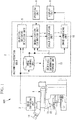
- the microscope system 100 includes a microscope 1, an arithmetic-operation unit 3, an operating unit 9, and a display unit 8.
- the microscope 1 includes: a stage 11 on which a specimen is mounted and that is movable in three-dimensional directions; objective lenses 12 for collecting light from the specimen; a revolver 13 for holding the two or more objective lenses 12 so that they are exchangeable; an eyepiece 14 for observing an observation image of the specimen with an unaided eye; and an image-capturing unit (camera for microscope) 2 for acquiring the observation image of the specimen.
- This embodiment describes an example case in which the objective lenses 12 are the only optical members for determining the optical magnification of the microscope 1, and there are four types of the objective lenses 12, namely, ⁇ 4, ⁇ 10, ⁇ 20, and x40, held on the revolver 13.
- the arithmetic-operation unit 3 is a calculation unit that uses, for example, a general-purpose personal computer, a workstation, a built-in processor, or an FPGA (Field Programmable Gate Array).
- the arithmetic-operation unit 3 includes: an image storage unit 4 for storing an image of each frame acquired by the image-capturing unit 2; an objective-switching detection unit (switching detection unit) 5 for detecting the switching among the objective lenses (optical members) 12 with the revolver 13; a magnification-estimation unit 6 that estimates the post-switching optical magnification when the switching among the objective lenses 12 is detected by the objective-switching detection unit 5; a scale-calculation unit 7 for calculating a scale on the basis of the optical magnification estimated by the magnification-estimation unit 6; and an image-combining unit 10 for generating a composite image having the scale calculated by the scale-calculation unit 7 superimposed on the latest image stored in the image storage unit 4.
- the arithmetic-operation unit 3 also includes an objective-information storage unit (magnification-information retaining unit) 15 for storing the information about the magnifications of all the objective lenses 12 provided in the microscope 1.
- an objective-information storage unit magnification-information retaining unit 15 for storing the information about the magnifications of all the objective lenses 12 provided in the microscope 1.
- the display unit 8 is configured to display an image combined by the image-combining unit 10.
- the objective-switching detection unit 5 is configured to detect that the objective lens 12 has been switched on the basis of a changeover time in images composed of a series of frames acquired by the image-capturing unit 2 in the same manner as in, for example, Patent Literature 1.
- the magnification-estimation unit 6 is configured to, as soon as the switching among the objectives is detected by the objective-switching detection unit 5, acquire one pre-detection image and one post-detection image stored in the image storage unit 4.
- the objective-switching detection unit 5 outputs the frame number at the start of switching and the frame number at the end of switching among the objective lenses 12, so that the magnification-estimation unit 6 acquires, from the image storage unit 4, the two images corresponding to those two frame numbers.
- the magnification-estimation unit 6 is configured to estimate a post-switching magnification according to the flowchart shown in Fig. 2 .
- the method will be described by way of an example where the magnification of the objective lens 12 has been switched, for example, from ⁇ 10 to ⁇ 20 through the operation of the revolver 13.
- the magnification-estimation unit 6 On the basis of the information about the magnifications of the objective lenses 12 stored in the objective-information storage unit 15, the magnification-estimation unit 6 performs processing for possible combinations of optical magnifications of all the objective lenses 12 provided in the microscope 1.
- a search magnification Ms is first determined (step S1). This embodiment assumes that search is made from a high magnification towards a low magnification, and therefore, ⁇ 40, the highest of the possible optical magnifications, is selected as the search magnification Ms.
- a known interpolation method such as the nearest neighbor, bilinear, or bicubic method, is used.
- a degree of similarity P between the search image Gs formed by scaling the post-switching image G2 and the pre-switching image G1 is calculated (degree-of-similarity calculation step S4).
- the degree of similarity P is calculated by carrying out template matching of the pre-switching image G1 with the search image Gs, formed by scaling the post-switching image G2, as a template.
- For template matching calculation of the degree of difference, typified by SAD (Sum of Absolute Difference) or SSD (Sum of Squared Difference), or calculation of the degree of correlation, typified by NCC (Normalized Cross-Correlation) or ZNCC (Zero-mean Normalized Cross-Correlation), may be used as known art.
- SAD Sud of Absolute Difference
- SSD Sud of Squared Difference
- NCC Normalized Cross-Correlation
- ZNCC Zero-mean Normalized Cross-Correlation
- phase restriction correlation method which is based on correlation of spatial frequencies, can also be used.
- step S5 If there is a degree of similarity that has already been calculated and stored, in addition to the newly calculated degree of similarity P, then it is compared with that stored degree of similarity Pmax in terms of the magnitude relationship (step S5), and if the newly calculated degree of similarity P is larger, the stored degree of similarity Pmax is updated, and then the corresponding search magnification Ms is stored in association with the degree of similarity Pmax (step S6).
- step S7 it is determined whether the degrees of similarity P for all the search magnifications Ms have been calculated. If the calculation has not been completed, the control returns to step S1, where the next possible search magnification Ms is determined and the next step S2 is executed.
- the degree of similarity P between the search image Gs, formed by scaling the pre-switching image G1, and the post-switching image G2 is calculated (degree-of-similarity calculation step S9).
- the degree of similarity P is calculated by carrying out template matching of the post-switching image G2 with the search image Gs, formed by scaling the pre-switching image G1, as a template, and then step S5 is executed.
- the degrees of similarity P for all possible search magnifications Ms have been calculated in this manner, a result like that shown in Fig. 5 is obtained.
- the degrees of similarity P as shown in Fig. 5 are a result of template matching based on ZNCC, with the values ranging from 0.0 to 1.0, where 1.0 indicates the highest degree of similarity, i.e., complete matching.
- the post-switching magnification is displayed on the display unit 8 so as to be perceivable.
- the magnification information for each of the objective lenses 12 is displayed in the form of a button, in which the estimated post-switching magnification is displayed in the form of a depressed button, distinctively from the other magnifications.
- the operating unit 9 is used for the user to set an optical magnification; it is used for the user to set a correct optical magnification in case the magnification-estimation unit 6 fails to estimate an optical magnification.
- the user may be allowed to set a correct magnification by depressing a button in Fig. 4 .
- the microscope system 100 and the method for estimating a magnification of the microscope 1 according to this embodiment afford an advantage in that the post-switching magnification of the objective lens 12 can be estimated with high accuracy, without adding a special device like a code revolver, by processing an image acquired by the image-capturing unit 2 of the microscope 1.
- the magnifications that are possible with the objective lenses 12 are stored in the objective-information storage unit 15 so that the magnification-estimation unit 6 estimates the post-switching magnification by switching only to the magnifications stored in the objective-information storage unit 15, thereby allowing the amount of calculation of the degrees of similarity to be minimized.
- the search magnification may be changed in prescribed steps within a prescribed range, thereby calculating the degrees of similarity.
Landscapes
- Physics & Mathematics (AREA)
- Chemical & Material Sciences (AREA)
- Analytical Chemistry (AREA)
- General Physics & Mathematics (AREA)
- Optics & Photonics (AREA)
- Engineering & Computer Science (AREA)
- Multimedia (AREA)
- Computer Vision & Pattern Recognition (AREA)
- Microscoopes, Condenser (AREA)
Abstract
Description
- The present invention relates to a microscope system and a method for estimating a microscope magnification.
- In order to visually perceive the size of an object of interest from an observation image acquired in a microscope, some conventional microscopes are provided with a function for superimposing a scale on the display screen on which the acquired image is displayed and a function for measuring the distance between two points on the display screen.
- There is also a known microscope that, because the magnification of the observation image is changed when the objective lens is switched using a revolver provided in the microscope, detects the switching of the objective lens from the acquired image and reports the switching so that the magnification information is changed (refer to, for example, Patent Literature 1).
- {Patent Literature}
- {PTL 1}
Japanese Unexamined Patent Application, Publication No. 2009-86314 - The microscope in
Patent Literature 1, however, does no more than notifying a user of information indicating that the objective lens has been switched, and this is burdensome to the user because he or she needs to again set the magnification of the objective lens after the switching. Although a special device, like a code revolver, for identifying the type of the objective lens placed in the optical path is also well known, such a special device is disadvantageous in terms of cost. - The present invention has been conceived in light of the above-described circumstances, and an object thereof is to provide a microscope system and a microscope-magnification estimating method capable of estimating a magnification after an optical member, such as an objective lens, has been switched, without providing a special device, like a code revolver.
- In order to achieve the above-described object, the present invention provides the following solutions.
- One aspect of the present invention provides a microscope system including: a microscope that includes an optical member disposed in an optical path so as to be switchable and that acquires an image of a specimen; and a magnification-estimation unit that, on the basis of a pre-switching optical magnification of the optical member in the microscope, estimates a post-switching optical magnification, wherein while scaling one of a pre-switching image acquired before switching of the optical member and a post-switching image acquired after switching of the optical member to a plurality of search images respectively corresponding to a plurality of search magnifications, the magnification-estimation unit calculates a degree of similarity to the other image and estimates the post-switching optical magnification from the search magnification when the calculated degree of similarity becomes the maximum.
- According to this aspect, the pre-switching image of the specimen is acquired by placing a predetermined optical member in the optical path of the microscope and acquiring an image of the specimen at a predetermined optical magnification. It is assumed that the optical magnification of the microscope at this time is known. Next, when the optical member is switched, the optical magnification of the microscope changes according to the optical member after the switching, and the magnification of the post-switching image obtained by acquiring an image of the specimen changes. The acquired pre-switching image and post-switching image are sent to the magnification-estimation unit, and while one of the images is being scaled to the plurality of search images respectively corresponding to the plurality of search magnifications, the degree of similarity to the other image is calculated.
- Since the pre-switching image and the post-switching image have a relationship in which a reduced version of one of the images constitutes a part of the other image, the degree of similarity sharply increases at a certain magnification in the course of comparison while the magnification of the one of the images is being changed. Therefore, the post-switching magnification can be estimated easily and with high accuracy, without having to provide a special device like a code revolver, from the search magnification when the degree of similarity becomes the maximum.
- In the above-described aspect, the magnification-estimation unit may sequentially set a search magnification and calculate the degree of similarity by scaling the post-switching image on the basis of the ratio of the pre-switching optical magnification to the search magnification if the set search magnification is equal to or larger than the pre-switching optical magnification or by scaling the pre-switching image on the basis of the ratio of the search magnification to the pre-switching optical magnification if the search magnification is smaller than the pre-switching optical magnification.
- According to this aspect, if the set search magnification is equal to or larger than the known optical magnification before switching, the post-switching image is scaled so as to be reduced at the ratio between the magnifications to calculate the degree of similarity between the pre-switching image and the scaled post-switching image, or if the search magnification is smaller than the known optical magnification before switching, the pre-switching image is scaled so as to be reduced at the above-described magnification to calculate the degree of similarity between the post-switching image and the scaled pre-switching image.
- Furthermore, in the above-described aspect, a switching detection unit for detecting switching of the optical member may be provided, wherein the magnification-estimation unit may estimate the post-switching optical magnification when switching of the optical member is detected by the switching detection unit.
- By doing so, since the magnification-estimation unit estimates an optical magnification when switching of the optical member is detected by the switching detection unit, the post-switching optical magnification can be estimated as appropriate at the time of a possible change in magnification.
- Furthermore, in the above-described aspect, a magnification-information retaining unit for retaining magnification information that can be employed by the optical member provided in the microscope may be provided, wherein the magnification-estimation unit may determine the search magnification to be changed when estimating the post-switching optical magnification on the basis of the magnification information retained in the magnification-information retaining unit.
- By doing so, since the magnification can be changed only for the magnification information retained in the magnification-information retaining unit, the post-switching optical magnification can be estimated efficiently.
- In addition, another aspect of the present invention is directed to a method for estimating a microscope magnification, including: a degree-of-similarity calculation step of, while scaling one of a pre-switching image acquired before switching of an optical member disposed in an optical path of a microscope so as to be switchable and a post-switching image acquired after switching of the optical member to a plurality of search images respectively corresponding to a plurality of search magnifications, calculating a degree of similarity to the other image; and a post-switching-magnification estimation step of calculating a post-switching optical magnification from the search magnification achieved when the degree of similarity calculated in the degree-of-similarity calculation step becomes the maximum.
- According to the present invention, there is an advantage in that the magnification after an optical member, such as an objective lens, has been switched can be estimated without providing a special device, like a code revolver.
-
- {
Fig. 1 }
Fig. 1 is an overall schematic diagram of a microscope system according to one embodiment of the present invention. - {
Fig. 2 }
Fig. 2 is a flowchart depicting a procedure for estimating a post-switching magnification with a magnification-estimation unit of the microscope system inFig. 1 . - {
Fig. 3 }
Fig. 3 is a diagram depicting the generation of search images and the calculation of degrees of similarity according to the flowchart inFig. 2 . - {
Fig. 4 }
Fig. 4 is a diagram depicting an example image in which a post-switching magnification estimated with the microscope system inFig. 1 is displayed with a scale. - {
Fig. 5 }
Fig. 5 is a diagram depicting the relationship between the degrees of similarity calculated in accordance with the estimating procedure inFig. 2 and search magnifications. - A
microscope system 100 according to one embodiment of the present invention will now be described with reference to the drawings. - As shown in
Fig. 1 , themicroscope system 100 according to this embodiment includes amicroscope 1, an arithmetic-operation unit 3, anoperating unit 9, and adisplay unit 8. - The
microscope 1 includes: astage 11 on which a specimen is mounted and that is movable in three-dimensional directions;objective lenses 12 for collecting light from the specimen; arevolver 13 for holding the two or moreobjective lenses 12 so that they are exchangeable; aneyepiece 14 for observing an observation image of the specimen with an unaided eye; and an image-capturing unit (camera for microscope) 2 for acquiring the observation image of the specimen. This embodiment describes an example case in which theobjective lenses 12 are the only optical members for determining the optical magnification of themicroscope 1, and there are four types of theobjective lenses 12, namely, ×4, ×10, ×20, and x40, held on therevolver 13. - The arithmetic-
operation unit 3 is a calculation unit that uses, for example, a general-purpose personal computer, a workstation, a built-in processor, or an FPGA (Field Programmable Gate Array). - The arithmetic-
operation unit 3 includes: animage storage unit 4 for storing an image of each frame acquired by the image-capturingunit 2; an objective-switching detection unit (switching detection unit) 5 for detecting the switching among the objective lenses (optical members) 12 with therevolver 13; a magnification-estimation unit 6 that estimates the post-switching optical magnification when the switching among theobjective lenses 12 is detected by the objective-switching detection unit 5; a scale-calculation unit 7 for calculating a scale on the basis of the optical magnification estimated by the magnification-estimation unit 6; and an image-combiningunit 10 for generating a composite image having the scale calculated by the scale-calculation unit 7 superimposed on the latest image stored in theimage storage unit 4. - The arithmetic-
operation unit 3 also includes an objective-information storage unit (magnification-information retaining unit) 15 for storing the information about the magnifications of all theobjective lenses 12 provided in themicroscope 1. - The
display unit 8 is configured to display an image combined by the image-combiningunit 10. - The objective-
switching detection unit 5 is configured to detect that theobjective lens 12 has been switched on the basis of a changeover time in images composed of a series of frames acquired by the image-capturingunit 2 in the same manner as in, for example,Patent Literature 1. - The magnification-
estimation unit 6 is configured to, as soon as the switching among the objectives is detected by the objective-switching detection unit 5, acquire one pre-detection image and one post-detection image stored in theimage storage unit 4. - More specifically, the objective-
switching detection unit 5 outputs the frame number at the start of switching and the frame number at the end of switching among theobjective lenses 12, so that the magnification-estimation unit 6 acquires, from theimage storage unit 4, the two images corresponding to those two frame numbers. - Next, a method for estimating a magnification using the
microscope system 100 according to this embodiment will be described. - The magnification-
estimation unit 6 is configured to estimate a post-switching magnification according to the flowchart shown inFig. 2 . - The method will be described by way of an example where the magnification of the
objective lens 12 has been switched, for example, from ×10 to ×20 through the operation of therevolver 13. - More specifically, it is assumed that a pre-switching magnification is M1=10 (known) and a post-switching magnification is M2=20 (unknown).
- On the basis of the information about the magnifications of the
objective lenses 12 stored in the objective-information storage unit 15, the magnification-estimation unit 6 performs processing for possible combinations of optical magnifications of all theobjective lenses 12 provided in themicroscope 1. - More specifically, a search magnification Ms is first determined (step S1). This embodiment assumes that search is made from a high magnification towards a low magnification, and therefore, ×40, the highest of the possible optical magnifications, is selected as the search magnification Ms.
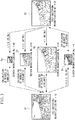
- Then, the search magnification Ms is compared with the pre-switching magnification M1 (step S2). If the search magnification Ms is equal to or higher than the pre-switching magnification M1, a post-switching image G2 is multiplied by M1/Ms. Because M1=10<Ms=40 in the example described above, the post-switching image G2 is multiplied by M1/Ms=1/4, and a search image Gs formed by scaling the post-switching image G2 to 1/4 is generated as shown in
Fig. 3 (search-image generation step S3). - For scaling, a known interpolation method, such as the nearest neighbor, bilinear, or bicubic method, is used.
- Next, a degree of similarity P between the search image Gs formed by scaling the post-switching image G2 and the pre-switching image G1 is calculated (degree-of-similarity calculation step S4).
- The degree of similarity P is calculated by carrying out template matching of the pre-switching image G1 with the search image Gs, formed by scaling the post-switching image G2, as a template. For template matching, calculation of the degree of difference, typified by SAD (Sum of Absolute Difference) or SSD (Sum of Squared Difference), or calculation of the degree of correlation, typified by NCC (Normalized Cross-Correlation) or ZNCC (Zero-mean Normalized Cross-Correlation), may be used as known art. In order to treat degrees of difference as degrees of similarity, lower degrees of difference may be treated as higher degrees of similarity. Known art called the phase restriction correlation method, which is based on correlation of spatial frequencies, can also be used.
- If there is a degree of similarity that has already been calculated and stored, in addition to the newly calculated degree of similarity P, then it is compared with that stored degree of similarity Pmax in terms of the magnitude relationship (step S5), and if the newly calculated degree of similarity P is larger, the stored degree of similarity Pmax is updated, and then the corresponding search magnification Ms is stored in association with the degree of similarity Pmax (step S6).
- Then, it is determined whether the degrees of similarity P for all the search magnifications Ms have been calculated (step S7), and if the calculation has not been completed, the control returns to step S1, where the next possible search magnification Ms is determined and the next step S2 is executed.
- For the next possible search magnifications Ms=20 and 10, the same processing as with the search magnification Ms=40 is carried out in step S2, and hence, the processing from step S3 to step S6 is repeated.
- On the other hand, if the search magnification Ms is smaller than the pre-switching magnification M1, i.e., if the search magnification Ms=4, as a result of the comparison in step S2, then a search image Gs formed by scaling the pre-switching image G1 to Ms/M1=4/10=1/2.5 is generated, as shown in
Fig. 3 (search-image generation step S8). - Then, the degree of similarity P between the search image Gs, formed by scaling the pre-switching image G1, and the post-switching image G2 is calculated (degree-of-similarity calculation step S9).
- More specifically, the degree of similarity P is calculated by carrying out template matching of the post-switching image G2 with the search image Gs, formed by scaling the pre-switching image G1, as a template, and then step S5 is executed.
- When the degrees of similarity P for all possible search magnifications Ms have been calculated in this manner, a result like that shown in
Fig. 5 is obtained. In the above-described example, the degree of similarity P is the maximum when the search magnification Ms=20. Note that the degrees of similarity P as shown inFig. 5 are a result of template matching based on ZNCC, with the values ranging from 0.0 to 1.0, where 1.0 indicates the highest degree of similarity, i.e., complete matching. - Then, if it is determined that the degrees of similarity P for all search magnifications Ms have been calculated in step S7, the search magnification Ms=20 corresponding to the stored degree of similarity Pmax is output as the post-switching magnification M2 (post-switching-magnification estimation step S10). In this manner, the post-switching magnification M2 can be estimated with high accuracy.
- If an estimated value of the post-switching magnification M2 is output from the magnification-
estimation unit 6, a scale is calculated in the scale-calculation unit 7, and then the calculated scale is superimposed on the latest image in the image-combiningunit 10 and is displayed on thedisplay unit 8, as shown inFig. 4 . Thus, there is an advantage in that as a result of the superimposed image being displayed on thedisplay unit 8, the user is relieved of a burdensome operation because he/she does not need to enter a new magnification. - In
Fig. 4 , the post-switching magnification is displayed on thedisplay unit 8 so as to be perceivable. In the example ofFig. 4 , the magnification information for each of theobjective lenses 12 is displayed in the form of a button, in which the estimated post-switching magnification is displayed in the form of a depressed button, distinctively from the other magnifications. - The
operating unit 9 is used for the user to set an optical magnification; it is used for the user to set a correct optical magnification in case the magnification-estimation unit 6 fails to estimate an optical magnification. For example, the user may be allowed to set a correct magnification by depressing a button inFig. 4 . - Thus, the
microscope system 100 and the method for estimating a magnification of themicroscope 1 according to this embodiment afford an advantage in that the post-switching magnification of theobjective lens 12 can be estimated with high accuracy, without adding a special device like a code revolver, by processing an image acquired by the image-capturingunit 2 of themicroscope 1. - Note that in this embodiment, the magnifications that are possible with the
objective lenses 12 are stored in the objective-information storage unit 15 so that the magnification-estimation unit 6 estimates the post-switching magnification by switching only to the magnifications stored in the objective-information storage unit 15, thereby allowing the amount of calculation of the degrees of similarity to be minimized. Alternatively, the search magnification may be changed in prescribed steps within a prescribed range, thereby calculating the degrees of similarity. - In addition, although this embodiment has been described by way of an example where the optical magnification of the
microscope 1 is changed only via theobjective lenses 12 provided so as to be switchable with therevolver 13, it can also be easily applied to an example where the magnification is switched with another optical member, like a variable power mechanism. -
- 1 Microscope
- 5 Objective-switching detection unit (switching detection unit)
- 6 Magnification-estimation unit
- 100 Microscope system
- S4, S9 Degree-of-similarity calculation step
- S10 Post-switching-magnification estimation step
Claims (5)
- A microscope system comprising:a microscope that includes an optical member disposed in an optical path so as to be switchable and that acquires an image of a specimen; anda magnification-estimation unit that, on the basis of a pre-switching optical magnification of the optical member in the microscope, estimates a post-switching optical magnification,wherein while scaling one of a pre-switching image acquired before switching of the optical member and a post-switching image acquired after switching of the optical member to a plurality of search images respectively corresponding to a plurality of search magnifications, the magnification-estimation unit calculates a degree of similarity to the other image and estimates the post-switching optical magnification from the search magnification when the calculated degree of similarity becomes the maximum.
- The microscope system according to claim 1, wherein the magnification-estimation unit sequentially sets a search magnification and calculates the degree of similarity by scaling the post-switching image on the basis of the ratio of the pre-switching optical magnification to the search magnification if the set search magnification is equal to or larger than the pre-switching optical magnification or by scaling the pre-switching image on the basis of the ratio of the search magnification to the pre-switching optical magnification if the search magnification is smaller than the pre-switching optical magnification.
- The microscope system according to claim 1 or 2, comprising:a switching detection unit for detecting switching of the optical member,wherein the magnification-estimation unit estimates the post-switching optical magnification when switching of the optical member is detected by the switching detection unit.
- The microscope system according to one of claims 1 to 3, comprising:a magnification-information retaining unit for retaining magnification information that can be employed by the optical member provided in the microscope,wherein the magnification-estimation unit determines the search magnification to be changed when estimating the post-switching optical magnification on the basis of the magnification information retained in the magnification-information retaining unit.
- A method for estimating a microscope magnification, comprising:a degree-of-similarity calculation step of, while scaling one of a pre-switching image acquired before switching of an optical member disposed in an optical path of a microscope so as to be switchable and a post-switching image acquired after switching of the optical member to a plurality of search images respectively corresponding to a plurality of search magnifications, calculating a degree of similarity to the other image; anda post-switching-magnification estimation step of calculating a post-switching optical magnification from the search magnification achieved when the degree of similarity calculated in the degree-of-similarity calculation step becomes the maximum.
Applications Claiming Priority (1)
| Application Number | Priority Date | Filing Date | Title |
|---|---|---|---|
| JP2016006398A JP6633917B2 (en) | 2016-01-15 | 2016-01-15 | Microscope system and method for estimating magnification of microscope |
Publications (1)
| Publication Number | Publication Date |
|---|---|
| EP3193201A1 true EP3193201A1 (en) | 2017-07-19 |
Family
ID=57206149
Family Applications (1)
| Application Number | Title | Priority Date | Filing Date |
|---|---|---|---|
| EP16195752.7A Withdrawn EP3193201A1 (en) | 2016-01-15 | 2016-10-26 | Microscope system and method for estimating microscope magnification |
Country Status (3)
| Country | Link |
|---|---|
| US (1) | US10151911B2 (en) |
| EP (1) | EP3193201A1 (en) |
| JP (1) | JP6633917B2 (en) |
Families Citing this family (1)
| Publication number | Priority date | Publication date | Assignee | Title |
|---|---|---|---|---|
| JP2018066845A (en) * | 2016-10-19 | 2018-04-26 | オリンパス株式会社 | Microscope system |
Citations (3)
| Publication number | Priority date | Publication date | Assignee | Title |
|---|---|---|---|---|
| EP1394739A1 (en) * | 2002-08-22 | 2004-03-03 | Christer Pihl Data Ab | Mosaicing from microscopic images of a specimen |
| JP2009086314A (en) | 2007-09-28 | 2009-04-23 | Olympus Corp | Camera for microscope |
| US20140210972A1 (en) * | 2011-10-11 | 2014-07-31 | Olympus Corporation | Focus control device, endoscope system, and focus control method |
-
2016
- 2016-01-15 JP JP2016006398A patent/JP6633917B2/en active Active
- 2016-10-26 EP EP16195752.7A patent/EP3193201A1/en not_active Withdrawn
- 2016-12-21 US US15/386,105 patent/US10151911B2/en not_active Expired - Fee Related
Patent Citations (3)
| Publication number | Priority date | Publication date | Assignee | Title |
|---|---|---|---|---|
| EP1394739A1 (en) * | 2002-08-22 | 2004-03-03 | Christer Pihl Data Ab | Mosaicing from microscopic images of a specimen |
| JP2009086314A (en) | 2007-09-28 | 2009-04-23 | Olympus Corp | Camera for microscope |
| US20140210972A1 (en) * | 2011-10-11 | 2014-07-31 | Olympus Corporation | Focus control device, endoscope system, and focus control method |
Also Published As
| Publication number | Publication date |
|---|---|
| US10151911B2 (en) | 2018-12-11 |
| JP6633917B2 (en) | 2020-01-22 |
| US20170205616A1 (en) | 2017-07-20 |
| JP2017126030A (en) | 2017-07-20 |
Similar Documents
| Publication | Publication Date | Title |
|---|---|---|
| RU2711625C2 (en) | Device, system and method of determining one or more optical parameters of lens | |
| JP5173665B2 (en) | Image capturing apparatus, distance calculation method thereof, and focused image acquisition method | |
| US10018826B2 (en) | Microscope system | |
| JP2015232476A (en) | Inspection device, inspection method, and program | |
| JP2012069090A (en) | Image processing apparatus and method | |
| US20180088307A1 (en) | Microscope imaging system | |
| JP2019066451A (en) | Image measurement apparatus, image measurement method, imaging apparatus and program | |
| JP6485116B2 (en) | Focus position detection device, focus position detection method, and computer program for focus position detection | |
| JP2013037166A (en) | Focus detector, and lens device and imaging device having the same | |
| US11069084B2 (en) | Object identification method and device | |
| US11385053B2 (en) | Distance measuring camera | |
| EP3193201A1 (en) | Microscope system and method for estimating microscope magnification | |
| US12205314B2 (en) | Image processing apparatus for a plurality of timeseries images acquired by an endoscope, image processing method, and recording medium | |
| JP2016099318A (en) | Stereo matching device, stereo matching program, and stereo matching method | |
| EP3825649A1 (en) | Ranging camera | |
| JP2018163365A (en) | Image processing device | |
| EP3443400A1 (en) | Variable working distance microscope | |
| US20150124077A1 (en) | Charged particle beam adjustment assistance device and method | |
| EP3194886A1 (en) | Positional shift amount calculation apparatus and imaging apparatus | |
| EP3173839A1 (en) | Microscope system and control method therefor | |
| EP4134644A1 (en) | System and method for extracting information on the spatial distribution of wavefronts | |
| JP2020181401A (en) | Image processing equipment, image processing methods and programs | |
| JP2015108670A (en) | Image processing device, electronic camera and image processing program | |
| US11143504B2 (en) | Image capture device and image capture system | |
| US10409051B2 (en) | Extraction of microscope zoom level using object tracking |
Legal Events
| Date | Code | Title | Description |
|---|---|---|---|
| PUAI | Public reference made under article 153(3) epc to a published international application that has entered the european phase |
Free format text: ORIGINAL CODE: 0009012 |
|
| STAA | Information on the status of an ep patent application or granted ep patent |
Free format text: STATUS: THE APPLICATION HAS BEEN PUBLISHED |
|
| AK | Designated contracting states |
Kind code of ref document: A1 Designated state(s): AL AT BE BG CH CY CZ DE DK EE ES FI FR GB GR HR HU IE IS IT LI LT LU LV MC MK MT NL NO PL PT RO RS SE SI SK SM TR |
|
| AX | Request for extension of the european patent |
Extension state: BA ME |
|
| STAA | Information on the status of an ep patent application or granted ep patent |
Free format text: STATUS: REQUEST FOR EXAMINATION WAS MADE |
|
| 17P | Request for examination filed |
Effective date: 20171012 |
|
| RBV | Designated contracting states (corrected) |
Designated state(s): AL AT BE BG CH CY CZ DE DK EE ES FI FR GB GR HR HU IE IS IT LI LT LU LV MC MK MT NL NO PL PT RO RS SE SI SK SM TR |
|
| STAA | Information on the status of an ep patent application or granted ep patent |
Free format text: STATUS: EXAMINATION IS IN PROGRESS |
|
| 17Q | First examination report despatched |
Effective date: 20180814 |
|
| STAA | Information on the status of an ep patent application or granted ep patent |
Free format text: STATUS: THE APPLICATION IS DEEMED TO BE WITHDRAWN |
|
| 18D | Application deemed to be withdrawn |
Effective date: 20190802 |