EP3193175B1 - Doppler flow radar - Google Patents
Doppler flow radar Download PDFInfo
- Publication number
- EP3193175B1 EP3193175B1 EP17150546.4A EP17150546A EP3193175B1 EP 3193175 B1 EP3193175 B1 EP 3193175B1 EP 17150546 A EP17150546 A EP 17150546A EP 3193175 B1 EP3193175 B1 EP 3193175B1
- Authority
- EP
- European Patent Office
- Prior art keywords
- velocity
- radar
- energy
- wire interface
- power
- Prior art date
- Legal status (The legal status is an assumption and is not a legal conclusion. Google has not performed a legal analysis and makes no representation as to the accuracy of the status listed.)
- Active
Links
Images


Classifications
-
- G—PHYSICS
- G01—MEASURING; TESTING
- G01S—RADIO DIRECTION-FINDING; RADIO NAVIGATION; DETERMINING DISTANCE OR VELOCITY BY USE OF RADIO WAVES; LOCATING OR PRESENCE-DETECTING BY USE OF THE REFLECTION OR RERADIATION OF RADIO WAVES; ANALOGOUS ARRANGEMENTS USING OTHER WAVES
- G01S13/00—Systems using the reflection or reradiation of radio waves, e.g. radar systems; Analogous systems using reflection or reradiation of waves whose nature or wavelength is irrelevant or unspecified
- G01S13/02—Systems using reflection of radio waves, e.g. primary radar systems; Analogous systems
- G01S13/50—Systems of measurement based on relative movement of target
- G01S13/58—Velocity or trajectory determination systems; Sense-of-movement determination systems
- G01S13/583—Velocity or trajectory determination systems; Sense-of-movement determination systems using transmission of continuous unmodulated waves, amplitude-, frequency-, or phase-modulated waves and based upon the Doppler effect resulting from movement of targets
-
- G—PHYSICS
- G01—MEASURING; TESTING
- G01F—MEASURING VOLUME, VOLUME FLOW, MASS FLOW OR LIQUID LEVEL; METERING BY VOLUME
- G01F1/00—Measuring the volume flow or mass flow of fluid or fluent solid material wherein the fluid passes through a meter in a continuous flow
- G01F1/66—Measuring the volume flow or mass flow of fluid or fluent solid material wherein the fluid passes through a meter in a continuous flow by measuring frequency, phase shift or propagation time of electromagnetic or other waves, e.g. using ultrasonic flowmeters
- G01F1/663—Measuring the volume flow or mass flow of fluid or fluent solid material wherein the fluid passes through a meter in a continuous flow by measuring frequency, phase shift or propagation time of electromagnetic or other waves, e.g. using ultrasonic flowmeters by measuring Doppler frequency shift
-
- G—PHYSICS
- G01—MEASURING; TESTING
- G01F—MEASURING VOLUME, VOLUME FLOW, MASS FLOW OR LIQUID LEVEL; METERING BY VOLUME
- G01F1/00—Measuring the volume flow or mass flow of fluid or fluent solid material wherein the fluid passes through a meter in a continuous flow
- G01F1/002—Measuring the volume flow or mass flow of fluid or fluent solid material wherein the fluid passes through a meter in a continuous flow wherein the flow is in an open channel
-
- G—PHYSICS
- G01—MEASURING; TESTING
- G01F—MEASURING VOLUME, VOLUME FLOW, MASS FLOW OR LIQUID LEVEL; METERING BY VOLUME
- G01F23/00—Indicating or measuring liquid level or level of fluent solid material, e.g. indicating in terms of volume or indicating by means of an alarm
- G01F23/22—Indicating or measuring liquid level or level of fluent solid material, e.g. indicating in terms of volume or indicating by means of an alarm by measuring physical variables, other than linear dimensions, pressure or weight, dependent on the level to be measured, e.g. by difference of heat transfer of steam or water
- G01F23/28—Indicating or measuring liquid level or level of fluent solid material, e.g. indicating in terms of volume or indicating by means of an alarm by measuring physical variables, other than linear dimensions, pressure or weight, dependent on the level to be measured, e.g. by difference of heat transfer of steam or water by measuring the variations of parameters of electromagnetic or acoustic waves applied directly to the liquid or fluent solid material
- G01F23/284—Electromagnetic waves
-
- G—PHYSICS
- G01—MEASURING; TESTING
- G01F—MEASURING VOLUME, VOLUME FLOW, MASS FLOW OR LIQUID LEVEL; METERING BY VOLUME
- G01F23/00—Indicating or measuring liquid level or level of fluent solid material, e.g. indicating in terms of volume or indicating by means of an alarm
- G01F23/22—Indicating or measuring liquid level or level of fluent solid material, e.g. indicating in terms of volume or indicating by means of an alarm by measuring physical variables, other than linear dimensions, pressure or weight, dependent on the level to be measured, e.g. by difference of heat transfer of steam or water
- G01F23/28—Indicating or measuring liquid level or level of fluent solid material, e.g. indicating in terms of volume or indicating by means of an alarm by measuring physical variables, other than linear dimensions, pressure or weight, dependent on the level to be measured, e.g. by difference of heat transfer of steam or water by measuring the variations of parameters of electromagnetic or acoustic waves applied directly to the liquid or fluent solid material
- G01F23/296—Acoustic waves
- G01F23/2962—Measuring transit time of reflected waves
-
- G—PHYSICS
- G01—MEASURING; TESTING
- G01P—MEASURING LINEAR OR ANGULAR SPEED, ACCELERATION, DECELERATION, OR SHOCK; INDICATING PRESENCE, ABSENCE, OR DIRECTION, OF MOVEMENT
- G01P5/00—Measuring speed of fluids, e.g. of air stream; Measuring speed of bodies relative to fluids, e.g. of ship, of aircraft
- G01P5/24—Measuring speed of fluids, e.g. of air stream; Measuring speed of bodies relative to fluids, e.g. of ship, of aircraft by measuring the direct influence of the streaming fluid on the properties of a detecting acoustical wave
- G01P5/241—Measuring speed of fluids, e.g. of air stream; Measuring speed of bodies relative to fluids, e.g. of ship, of aircraft by measuring the direct influence of the streaming fluid on the properties of a detecting acoustical wave by using reflection of acoustical waves, i.e. Doppler-effect
-
- G—PHYSICS
- G01—MEASURING; TESTING
- G01S—RADIO DIRECTION-FINDING; RADIO NAVIGATION; DETERMINING DISTANCE OR VELOCITY BY USE OF RADIO WAVES; LOCATING OR PRESENCE-DETECTING BY USE OF THE REFLECTION OR RERADIATION OF RADIO WAVES; ANALOGOUS ARRANGEMENTS USING OTHER WAVES
- G01S13/00—Systems using the reflection or reradiation of radio waves, e.g. radar systems; Analogous systems using reflection or reradiation of waves whose nature or wavelength is irrelevant or unspecified
- G01S13/02—Systems using reflection of radio waves, e.g. primary radar systems; Analogous systems
- G01S13/50—Systems of measurement based on relative movement of target
- G01S13/58—Velocity or trajectory determination systems; Sense-of-movement determination systems
-
- G—PHYSICS
- G01—MEASURING; TESTING
- G01S—RADIO DIRECTION-FINDING; RADIO NAVIGATION; DETERMINING DISTANCE OR VELOCITY BY USE OF RADIO WAVES; LOCATING OR PRESENCE-DETECTING BY USE OF THE REFLECTION OR RERADIATION OF RADIO WAVES; ANALOGOUS ARRANGEMENTS USING OTHER WAVES
- G01S13/00—Systems using the reflection or reradiation of radio waves, e.g. radar systems; Analogous systems using reflection or reradiation of waves whose nature or wavelength is irrelevant or unspecified
- G01S13/02—Systems using reflection of radio waves, e.g. primary radar systems; Analogous systems
- G01S13/50—Systems of measurement based on relative movement of target
- G01S13/58—Velocity or trajectory determination systems; Sense-of-movement determination systems
- G01S13/581—Velocity or trajectory determination systems; Sense-of-movement determination systems using transmission of interrupted pulse modulated waves and based upon the Doppler effect resulting from movement of targets
-
- G—PHYSICS
- G01—MEASURING; TESTING
- G01S—RADIO DIRECTION-FINDING; RADIO NAVIGATION; DETERMINING DISTANCE OR VELOCITY BY USE OF RADIO WAVES; LOCATING OR PRESENCE-DETECTING BY USE OF THE REFLECTION OR RERADIATION OF RADIO WAVES; ANALOGOUS ARRANGEMENTS USING OTHER WAVES
- G01S13/00—Systems using the reflection or reradiation of radio waves, e.g. radar systems; Analogous systems using reflection or reradiation of waves whose nature or wavelength is irrelevant or unspecified
- G01S13/86—Combinations of radar systems with non-radar systems, e.g. sonar, direction finder
- G01S13/862—Combination of radar systems with sonar systems
-
- G—PHYSICS
- G01—MEASURING; TESTING
- G01S—RADIO DIRECTION-FINDING; RADIO NAVIGATION; DETERMINING DISTANCE OR VELOCITY BY USE OF RADIO WAVES; LOCATING OR PRESENCE-DETECTING BY USE OF THE REFLECTION OR RERADIATION OF RADIO WAVES; ANALOGOUS ARRANGEMENTS USING OTHER WAVES
- G01S13/00—Systems using the reflection or reradiation of radio waves, e.g. radar systems; Analogous systems using reflection or reradiation of waves whose nature or wavelength is irrelevant or unspecified
- G01S13/88—Radar or analogous systems specially adapted for specific applications
-
- G—PHYSICS
- G01—MEASURING; TESTING
- G01S—RADIO DIRECTION-FINDING; RADIO NAVIGATION; DETERMINING DISTANCE OR VELOCITY BY USE OF RADIO WAVES; LOCATING OR PRESENCE-DETECTING BY USE OF THE REFLECTION OR RERADIATION OF RADIO WAVES; ANALOGOUS ARRANGEMENTS USING OTHER WAVES
- G01S7/00—Details of systems according to groups G01S13/00, G01S15/00, G01S17/00
- G01S7/02—Details of systems according to groups G01S13/00, G01S15/00, G01S17/00 of systems according to group G01S13/00
- G01S7/28—Details of pulse systems
-
- G—PHYSICS
- G01—MEASURING; TESTING
- G01S—RADIO DIRECTION-FINDING; RADIO NAVIGATION; DETERMINING DISTANCE OR VELOCITY BY USE OF RADIO WAVES; LOCATING OR PRESENCE-DETECTING BY USE OF THE REFLECTION OR RERADIATION OF RADIO WAVES; ANALOGOUS ARRANGEMENTS USING OTHER WAVES
- G01S7/00—Details of systems according to groups G01S13/00, G01S15/00, G01S17/00
- G01S7/02—Details of systems according to groups G01S13/00, G01S15/00, G01S17/00 of systems according to group G01S13/00
- G01S7/28—Details of pulse systems
- G01S7/285—Receivers
- G01S7/292—Extracting wanted echo-signals
-
- G—PHYSICS
- G01—MEASURING; TESTING
- G01S—RADIO DIRECTION-FINDING; RADIO NAVIGATION; DETERMINING DISTANCE OR VELOCITY BY USE OF RADIO WAVES; LOCATING OR PRESENCE-DETECTING BY USE OF THE REFLECTION OR RERADIATION OF RADIO WAVES; ANALOGOUS ARRANGEMENTS USING OTHER WAVES
- G01S7/00—Details of systems according to groups G01S13/00, G01S15/00, G01S17/00
- G01S7/02—Details of systems according to groups G01S13/00, G01S15/00, G01S17/00 of systems according to group G01S13/00
- G01S7/35—Details of non-pulse systems
- G01S7/352—Receivers
- G01S7/354—Extracting wanted echo-signals
-
- G—PHYSICS
- G06—COMPUTING OR CALCULATING; COUNTING
- G06F—ELECTRIC DIGITAL DATA PROCESSING
- G06F13/00—Interconnection of, or transfer of information or other signals between, memories, input/output devices or central processing units
- G06F13/38—Information transfer, e.g. on bus
- G06F13/42—Bus transfer protocol, e.g. handshake; Synchronisation
Definitions
- the present invention relates to a velocity measurement device for measuring the velocity of a moving media in a channel, and to a method for measuring the velocity of a moving media in a channel.
- the velocity measurement may be used to determine the flow of the media in the channel.
- the device and method measure the velocity using Doppler radar velocity measurement techniques.
- One example situation is in a sewer system, where measuring the flow of sewage can help locate blockages (from slow flow), predict pumping requirements in pumping stations, predict if spills are to occur, and estimate the amount of sewage spilled where spills do occur.
- the flow can be determined by measuring the velocity and depth of the media.
- the velocity measurement determines both the speed and direction of movement.
- One technique used for measuring the velocity is Doppler radar.
- Doppler radar devices have a control unit and a measurement unit. Doppler radar devices have high power consumption, and so the control unit is typically powered by mains power. Separate connections are used to provide power from the control unit to the measurement unit, and to communicate the measured velocity between the measurement unit and the control unit.
- US 2015/007655 teaches that in order to determine a level and the flow speed of a medium, FMCW transmission signals and CW transmission signals are emitted alternately. Using the Doppler effect, the flow speed of the medium can be determined from the reflected CW signal. The level is determined from the reflected FMCW signal.
- US 2010/123614 discloses a radar level gauge system comprising power management circuitry for regulating operating power to be used by a microwave unit and a processing circuitry of the radar level gauge system.
- the power management circuitry comprises a DC-DC converter having an input terminal connected to the interface, an output terminal connected to the microwave unit and the processing circuitry, and a reference terminal connected to an electrical reference point, wherein a first voltage level at the input terminal and a second voltage level at the output terminal relates to a reference voltage level at the electrical reference point.
- the power management circuitry further comprises an energy storage capacitor connected between the input and output terminals of the DC-DC converter.
- US6014100 discloses a RADAR sensor for measuring the level of material that utilizes conventional medium- or high-power microwave transmitter and microwave receiver devices, while utilizing only the relatively small amount of current supplied by a conventional low current two-wire process control loop.
- a transmit/receive unit and a control unit are operated intermittently to generate readings, and are set to a current-saving or even currentless standby mode between these periods of active measurement.
- circuit components such as capacitors collect and store power to be used for the comparably high-power requirement during the active measurement cycles.
- the inactive standby periods are preferably long compared to the duration of the measurement periods. This permits operation with power entirely supplied from a common two-wire 4-20 mA process control loop.
- a velocity measurement device for measuring the velocity of a moving media in a channel, the velocity measurement device including a radar unit having: a radar module arranged to measure the velocity of the media using the Doppler effect; and a two wire interface to the radar unit arranged to receive power from an external power source, and provide data transfer between the radar unit and an external control unit.
- the radar unit further includes: an energy store arranged to: receive energy available on the two wire interface to charge the energy store; store the received energy; and supply the stored energy to the radar module when a velocity measurement is performed; and a radar unit controller arranged to, during an active period of the device: control the radar module to take one or more readings of the velocity of the media to provide a measurement of the velocity; and control operation of the radar unit to charge the energy store.
- the two wire interface is inactive between active periods of the device, such that no power is delivered to the radar unit between active periods.
- the power delivered over the two wire interface during a reading may be insufficient to power the radar module directly, and the energy stored in the energy store over the active period is sufficient to power the one or more readings.
- the radar module may be arranged to measure the velocity of the moving media within the active period of the device, wherein the active period is divided into a first portion in which the velocity of the media is measured, and a second portion in which the measured velocity is communicated to the external control unit, and wherein the energy store is charged during at least the first portion of the active period.
- the radar unit controller is further arranged to: determine the energy stored in the energy store; determine the proportion of the energy that can be used in a velocity measurement; and control the radar module to measure the velocity based on the determined portion of the energy that can be used.
- the radar unit controller may be arranged to vary one or more of: an output power of the radar module; a measurement duration; a number of repeat readings in the active period; an interval between readings in the active period; and a number of individual transmitters and/or receivers used based on the determined portion of the energy that can be used.
- the radar unit controller may be arranged to leave a minimum level of energy in the energy store, such that the measurement can be repeated in a subsequent active period without the energy store being replenished.
- the radar unit controller may be arranged to omit a velocity measurement if it is determined that the energy store does not have sufficient energy to power the radar module and leave the minimum level of energy in the energy store; and only charge the energy store during the active period.
- the velocity measurement device may include: an external control unit arranged to: control operation of the radar unit; and communicate with the radar unit over the two wire interface.
- the external control unit may include a power supply for providing power to the radar unit over the two wire interface, and powering operation of the external control unit.
- the power supply may be a rechargeable power supply.
- the power supply may be a battery.
- the external control unit may be arranged to control the operation of the radar unit such that the velocity is measured intermittently, and the external control unit may be arranged to deactivate the two wire interface between velocity measurements.
- the external control unit may be arranged to determine the duration between velocity measurements based on one or more of: a default value, a user input, and one or more previous velocity measurements.
- the radar module may be arranged to use microwave radar to measure the velocity of the media.
- the radar module may include radar means having: means for transmitting microwaves; means for detecting microwaves reflected from the moving media; and means for determining the velocity of the media based on the reflected microwaves.
- the two wire interface may be arranged to carry a maximum current.
- the current on the two wire interface may be varied between a first current and a second current, both lower than the maximum current, to transfer data between the external control unit and the radar unit.
- the current on the two wire interface may be higher than the second current to indicate an error message.
- the current on the two wire interface may be higher than the second current when charging the energy store.
- the current on the two wire interface may be modulated when the external control unit is being used to configure the radar unit prior to use.
- the radar unit may include a retentive memory to store information relating to the velocity measurements.
- the memory may be a non-volatile random access memory.
- an external control unit for controlling the operation of a radar unit arranged to measure the velocity of a moving media in a channel using the Doppler effect, the external control unit having: a two wire interface from the external control unit arranged to supply power to the radar unit, and provide data transfer between the external control unit and the radar unit
- the power supply may be a rechargeable power supply.
- the power supply may be a battery.
- the external control unit may include: a controller arranged to: control the operation of the radar unit such that the velocity is measured intermittently; and deactivate the two wire interface between velocity measurements.
- the controller may be arranged to determine the duration between velocity measurements based on one or more of: a default value, a user input, and one or more previous velocity measurements.
- a velocity measurement device for measuring the velocity of a moving media in a channel, the velocity measurement device comprising: an external control unit as discussed above; and a radar unit arranged to measure the velocity of a moving media in a channel using the Doppler effect, the radar unit in communication with the external control unit over the two wire interface, and provided with power over the two wire interface.
- a flow measurement device for measuring the flow rate of a media in a channel
- the flow measurement device including: a level measurement device for determining the level of the media in the channel; and a velocity measurement device according to the first aspect or the third aspect, for measuring the velocity of the media in the channel, wherein the flow measurement device is arranged to determine the flow based on the measured level and the measured velocity.
- a method of measuring the velocity of a media in a channel including: activating a two wire interface to supply power from an external power source to a radar unit; at the radar unit, receiving power over the two wire interface; storing energy received on the two wire interface in an energy store of the radar unit; with a radar module of the radar unit, measuring the velocity of the media in the channel using the Doppler effect by taking one or more readings of the velocity of the media, wherein stored energy from the energy store is supplied to the radar module when a velocity measurement is performed; transferring the measured velocity to an external control unit over the two wire interface; and on completion of the measurement, deactivating the two wire interface, such that no power is delivered to the radar unit.
- the power delivered over the two wire interface during a reading may be insufficient to power the radar module directly, and the energy stored in the energy store over the active period is sufficient to power the radar module.
- Each velocity measurement may occur whilst the two wire interface is activated for an active period, wherein the active period is divided into a first portion in which the velocity of the moving media is measured, and a second portion in which the measured velocity is communicated to the external control unit.
- the method may also include charging the energy store during at least the first portion of the active period.
- the method may include: determining the energy stored in the energy store; determining the proportion of the energy that can be used in a velocity measurement; and control the radar module to measure the velocity based on the determined portion of the energy that can be used.
- the method may include varying one or more of: an output power of the radar module; a measurement duration; a number of repeat readings in a measurement; an interval between repeat readings; and a number of individual transmitters and/or receivers used based on the determined portion of the energy that can be used.
- Determining the proportion of the energy that can be used in a velocity measurement may include leaving a minimum level of energy in the energy store, such that the measurement can be repeated without the energy store being replenished.
- the method may include omitting a velocity measurement if it is determined that the energy store does not have sufficient energy to power the radar module and leave the minimum level of energy in the energy store, and only charge the energy store during the first portion of the active period.
- the method may include: using an external control unit to control operation of the radar unit.
- the external control unit may include a power source for providing power to the radar unit over the two wire interface, and powering the control unit.
- the method may include: powering the radar unit from the external control unit.
- the method may include: powering the external control unit with a rechargeable power supply.
- the method may further include: powering the control unit with a battery.
- the method may include: measuring the velocity intermittently; and deactivating the two wire interface between velocity measurements.
- the method may include: determining the duration between velocity measurements based on one or more of: a default value, a user input, and one or more previous velocity measurements.
- the method may include using microwave radar to measure the velocity of the media.
- the method may include: varying the current on the two wire interface between a first current and second current, to transfer data between the control unit and the radar unit.
- the method may include setting the current on the two wire interface higher than the second current, and lower than a maximum current to indicate an error message.
- the method may include setting the current on the two wire interface higher than the second current, and lower than a maximum current during charging of the energy store.
- the current on the two wire interface may be higher than the second current when the control unit is being used to configure the radar unit, prior to use.
- a method of measuring the flow of a moving media in a channel including: measuring the level of media in the channel; measuring the velocity of the media in the channel according to the third aspect; and determining the flow based on the measured level and the measured velocity.
- a machine readable medium having instructions which when read by a machine cause the machine to perform the method of the third or fourth aspect.
- the machine readable medium referred to in any of the above aspects of the invention may be any of the following: a CDROM; a DVD ROM / RAM (including -R/-RW or +R/+RW); a hard drive; a memory (including a USB drive; an SD card; a compact flash card or the like); a transmitted signal (including an Internet download, ftp file transfer of the like); a wire; etc.
- Figure 1 shows a schematic illustration of a channel 1 carrying a flowing media 3, such as water.
- a flow measurement device 11 is positioned in the channel 1, above the water surface 7, to measure the flow rate of the water 3.
- the flow measurement device 11 includes a level measurement device 15, and a velocity measurement device 17.
- the level measurement device 15 emits ultrasound waves, receives reflections from the water surface 7, and, based on the time of flight, determines the distance from the level measurement device 15 to the water surface 7. Using the known distance from the level measurement device 15 to the base 5 of the channel 1, the depth of the water can be determined.
- the velocity measurement device 17 uses reflections of waves from the water surface 7 to determine the velocity of the water 3 in the channel 1.
- the level measurement device 15 and velocity measurement device 17 pass the determined depth and velocity to a controller 13, which uses these variables to determine the flow.
- FIG. 2 shows an example of a velocity measurement device 17 that uses Doppler radar to determine the velocity of the water 3.
- the velocity measurement device 17 is split into two separate units, an external control unit 19 and a radar unit 21.
- the external control unit 19 includes a battery 35 for powering the velocity measurement device 17, and a controller 37 for controlling operation of the velocity measurement device 17.
- the radar unit 21 includes a radar module 33 for transmitting and receiving microwaves, and determining the velocity based on the Doppler shift of the reflections.
- the radar module 33 may be any suitable radar means for carrying out Doppler radar velocity measurements, and may include one or more microwave transmitters, and receivers, and processing means to determine the velocity based on the time of flight of the reflections from the water.
- the external control unit 19 and radar unit 21 are coupled by a two wire interface 23 (also called a two wire loop).
- the two wire interface 23 is used to transfer power from the external control unit 19 to the radar unit 21, and for data transfer between the external control unit 19 and the radar unit 21.
- use of the two wire interface for power transfer and data transfer provides a simple, lightweight and small unit that can be permanently installed in confined spaces, or used as part of a portable apparatus.
- the external control unit 19 behaves as a master, and controls the operation of the radar unit 21, as a slave. In particular, the external control unit 19 controls when the radar unit 21 takes a measurement of the velocity. The operation of the external control unit 19, and hence the velocity measurement device 17 as a whole is managed by the external control unit controller 37.
- the external control unit 19 is also arranged to minimise its power consumption between measurements. This ensures energy losses between measurements are minimised.
- Figure 3 shows an example of the current 100 on the two wire interface 23 over a period incorporating three separate velocity measurements 102a, 102b, 102c.
- the time 104 between the velocity measurements 102 can be fixed, or variable, and can be based on a number of factors, including: user input, and/or a default time, and/or the previous level over water in the channel 1 or in a sump or well (not shown) the channel 1 flows into or out of and/or the previously measured flows.
- the first measurement 102a may determine a relatively fast flow rate for water flowing into a nearly full sump. Therefore, the time 104a between the first measurement 102a and the second measurement 102b may be set relatively short, as there is a risk of the sump overflowing and so regular monitoring is required. However, the second measurement 102b may determine that the flow rate has slowed, and so the time between the second measurement 102b and the third measurement 102c may be set relatively long.
- the time 104 between measurements 102 can be any suitable value, and may be of the order of a few seconds, a few minutes, a few hours, or any time in between or longer.
- the current on the two wire interface 23 is 0 milliamps.
- the two wire interface 23 activates.
- Figure 4 shows the current during a measurement (or active period) 102 in more detail.
- the current can be any value between 0 milliamps and a maximum 106a of 25 milliamps.
- the period when the two-wire interface 23 is active is divided into a first portion in which the measurement occurs, and a second portion in which data transfer occurs. In the second portion, currents between a lower boundary 106c of 4 milliamps and an upper boundary 106b of 20 milliamps are used to communicate information over the interface 23.
- the current is set, by the external control unit 19, to a first value 116, outside the communication range 106b,c, such as 22 milliamps.
- the radar unit 21 includes a second controller 31.
- the radar unit controller 31 detects the current 116 and determines that an active period has started.
- the radar unit 21 includes an energy store 29 which is used to power the radar module 33.
- the energy store 29 is charged for longer than the radar module 33 is used for. This means that the energy store 29 has more energy than is delivered over the two wire interface 23 during the period the radar module 33 is operated for, and so can deliver higher power to the radar module 33 than the two wire interface 23 during use.
- the use of the energy store 29 means that in at least some embodiments, high power Doppler radar equipment to be used, but the flow measurement device remains low power overall.
- the radar unit controller 31 determines how much energy is in the energy store 29, and determines how much energy can be used by the radar module 33, whilst still leaving sufficient energy to repeat the same measurement, without the energy store being replenished.
- the radar unit controller 31 then controls the radar unit 21 to take measurements of the velocity.
- Each measurement may include several individual readings of the velocity by emitting a wave a detecting the reflection, and the radar module 33 is active for the period the reading is taken for.
- Each reading lasts for a short duration, due to the time of flight for waves to reflect from the water surface 7.
- the number of waves/reflections used in a reading (controlled by the duration of each reading), the output power in the radar waves, the number of repeat readings, the interval between repeat reading and the number of transmitter and receivers used can be controlled based on the energy in the energy store 29. Generally, the more waves/reflections, longer measurement duration and higher power, the more accurate (and hence higher quality) the measurement, but the more power is consumed. In at least some embodiments, control of the different properties of the measurements means that energy in the energy store 29 is used in an efficient manner.
- the velocity measurements are complete.
- the current is set to a second value 118, within the communication range.
- the second current 118 is proportional to the determined velocity.
- the radar unit 21 includes a communication module 25, which converts the determined velocity into the second current 118.
- the external control unit 19 includes a communication module 27, which reconverts the current back to the velocity for use in the external control unit 19.
- the two-wire interface 23 is deactivated, and the current returns to 0 milliamps.
- Measurement occurs in the first portion of the active period 102, and communication in the second portion. Over both portions, the current on the two-wire interface 23 is also used to charge the energy store 29, such that it is not depleted over continuous use.
- the length 110 of the first portion of the active period is between 4 and 5 seconds. This provides sufficient time for measurements and charging. Typically, the measurements may only take a few milliseconds, over the course of first portion.
- the second portion is a small fraction of a second in length. For example, the second portion is a few milliseconds in length.
- the current in the communication range 106b,c is calibrated depending on the physical characteristics of the channel 1, so that the lowest possible velocity in the channel is transferred by a second current 118 of 4 milliamps, and the fastest possible velocity is transferred by a second current 118 of 20 milliamps. In this way, the same device can be used in different channels 1, and still provide high resolution.
- the radar unit controller 31 determines that no measurement is possible due to insufficient charge in the energy store 29, then the radar unit controller 31 skips the measurement, and uses the first portion of the active period 102 for charging only. In the second portion of the active period 102, the two wire interface 23 may also be used to transfer an error code. This may be in the case that the velocity measurement was not possible due to system malfunction, or insufficient charge in the energy store 29.
- the external control unit controller 37 may be arranged to determine patterns in the error codes. For example, if error codes occur every other measurement, the external control unit 19 may determine that insufficient energy is getting into the energy store 29, and increase the duration of the first portion, or activate the two wire interface 23 for a charging period to provide further charge into the energy store 29. Alternatively, for a number of consecutive error codes, the external control unit 19 may determine a system malfunction.
- the error code is transferred by a current set outside the communication range 106b,c.
- the first current level 116 may be used as an error code. Different current levels may also be used for different error codes.
- the first current 116 may be used to indicate insufficient charge, and a second current (for example 25 milliamps, may be used to indicate other errors.
- the external control unit 19 can also be used to provide configuration and setup commands to the radar unit 21 prior to use. For example, the length of the first potion of the active period 102 may be set, and the communication range may be calibrated. This can be done by modulation of the current over the two-wire interface 23. The modulation can be encoded and decoded by the controllers 37, 31 in the radar unit 21 and external control unit 19. During operation when the setup and configuration is being carried, out, the current on the two wire interface 23 can provide additional charging.
- the radar unit 21 includes a small non-volatile lower power memory 39. This is a 4 kilobyte non-volatile memory that is used to store the velocity determined in at least the most recent measurement. The memory may also store other related information, and more than the single most recent measurement.
- the memory 39 can be read over the two wire interface 23. At the end of the active period, the memory is updated and/or overwritten with the new velocity reading.
- the operation described above ensures that the battery 35 in the external control unit 19 is used in an efficient manner, and the battery life may be extended to years in length, whilst still allowing the most accurate possible readings.
- the external control unit 19 may be provided separately to the radar unit 21.
- the external control unit 19 may be any suitable device that uses the same communication protocols as the radar unit 21.
- the external control unit 19 may be any handheld or portable computer (not shown).
- the radar unit 21 may be used interchangeably with any suitable external control unit 19.
- the protocols may be provided separately, so any existing computer may be used as the external control unit 19.
- the external control unit 19 may be part of a controller 13 for a flow measurement device 11, or the external control unit 19 may be incorporated into the controller 13 for a flow measurement device 11. In this case, the velocity measurement is used to determine the flow.
- timings discussed above given are by way of example only, and any suitable timings may be used.
- the lengths of the respective portions 110, 112, and the total lengths of the active period 108 should be sufficient to ensure readings can be taken, the results communicated and charge is transferred to the energy store 29.
- the active period is of fixed length 110.
- the active period length 110 may be variable.
- the active period length 110 may be varied on a similar basis to the gap between measurements, for example, user input, previous measurements and the like.
- the active period length 110 may vary following a predefined pattern.
- the currents given above are also only given by way of example only, and any suitable ranges may be used. Furthermore, in the above examples, only currents above the maximum in the communication range 106b, and below the overall maximum 106a for the two wire interface 23 are used. However, currents below the minimum in the communication range 106c, and above 0 milliamps could also be used. Furthermore, in some examples, the current may be at or below the maximum in the communication range 106b for charging.
- the radar unit controller 31 may use different criteria for determining how much energy from the energy store 29 can be used. For example, it may determine the useable energy in the energy store 29 such that only the minimum accuracy measurement can be repeated without further charging, or it may leave a preset amount of energy in the energy store 29. Alternatively, it may try to use all of the energy in the energy store 29, without leaving any in reserve.
- the radar unit controller 31 may be arranged to control the time 104 between measurements, based on the amount of energy in the energy store 29.
- the current on the two wire interface 23 is modulated to provide setup and configuration commands. It will be appreciated that any suitable communication protocol may be used instead. For example, the absolute value of the current may be set to different levels. Similarly, any suitable protocol may be used to communicate the measured velocity.
- the battery may be any suitable type of power supply, and may be rechargeable.
- the memory 39 may be any suitable non-volatile memory.
- the memory 39 is a 4 kilobyte memory.
- the memory 39 may be any suitable size, down to 16 bit. The amount of past information stored in the memory 39 will vary in dependence on the size of the memory 39.
- any suitable level measurement device 15 can be used.
- the level measurement device may be powered from the same battery 35 as the velocity measurement device 17, or a different battery (not shown).
- the level measurement device 15 may use a similar two wire loop, with similar control to the velocity measurement device, or not.
- the two measurement devices 15, 17 may also be provided in the same housing or different housing.
- the velocity measurement device 17 may be provided on its own, without incorporation in a flow measurement device 11.
- the flow measurement device 11 and/or velocity measurement device 17 are for use with any type of media, such as, but not limited to, fluids and solids.
- the controller 31, 37 may be any suitable processors, controllers, or combination of the two.
- the controller may also be implemented by a combination of discrete electronic components (such as op-amps comparators) arranged so as to perform the function of comparing levels of voltages and current, and the ability to switch on and off other electronic circuitries.
Landscapes
- Engineering & Computer Science (AREA)
- Physics & Mathematics (AREA)
- Radar, Positioning & Navigation (AREA)
- Remote Sensing (AREA)
- General Physics & Mathematics (AREA)
- Computer Networks & Wireless Communication (AREA)
- Electromagnetism (AREA)
- Fluid Mechanics (AREA)
- Theoretical Computer Science (AREA)
- Thermal Sciences (AREA)
- Acoustics & Sound (AREA)
- General Engineering & Computer Science (AREA)
- Multimedia (AREA)
- Aviation & Aerospace Engineering (AREA)
- Radar Systems Or Details Thereof (AREA)
Description
- The present invention relates to a velocity measurement device for measuring the velocity of a moving media in a channel, and to a method for measuring the velocity of a moving media in a channel. In particular, but not exclusively, the velocity measurement may be used to determine the flow of the media in the channel. The device and method measure the velocity using Doppler radar velocity measurement techniques.
- There are many different scenarios where it can be useful to measure the flow of a moving media. One example situation is in a sewer system, where measuring the flow of sewage can help locate blockages (from slow flow), predict pumping requirements in pumping stations, predict if spills are to occur, and estimate the amount of sewage spilled where spills do occur.
- Typically, the flow can be determined by measuring the velocity and depth of the media. The velocity measurement determines both the speed and direction of movement. One technique used for measuring the velocity is Doppler radar.
- Known Doppler radar devices have a control unit and a measurement unit. Doppler radar devices have high power consumption, and so the control unit is typically powered by mains power. Separate connections are used to provide power from the control unit to the measurement unit, and to communicate the measured velocity between the measurement unit and the control unit.
- Existing flow measurement devices including Doppler radar for the velocity measurement are bulky and difficult to move and install. This can be problematic when measurements are required in confined spaces, for example sewers, or measurements are only required on a temporary basis.
-
US 2015/007655 teaches that in order to determine a level and the flow speed of a medium, FMCW transmission signals and CW transmission signals are emitted alternately. Using the Doppler effect, the flow speed of the medium can be determined from the reflected CW signal. The level is determined from the reflected FMCW signal. -
US 2010/123614 discloses a radar level gauge system comprising power management circuitry for regulating operating power to be used by a microwave unit and a processing circuitry of the radar level gauge system. The power management circuitry comprises a DC-DC converter having an input terminal connected to the interface, an output terminal connected to the microwave unit and the processing circuitry, and a reference terminal connected to an electrical reference point, wherein a first voltage level at the input terminal and a second voltage level at the output terminal relates to a reference voltage level at the electrical reference point. The power management circuitry further comprises an energy storage capacitor connected between the input and output terminals of the DC-DC converter. -
US6014100 discloses a RADAR sensor for measuring the level of material that utilizes conventional medium- or high-power microwave transmitter and microwave receiver devices, while utilizing only the relatively small amount of current supplied by a conventional low current two-wire process control loop. A transmit/receive unit and a control unit are operated intermittently to generate readings, and are set to a current-saving or even currentless standby mode between these periods of active measurement. During the inactive standby period, circuit components such as capacitors collect and store power to be used for the comparably high-power requirement during the active measurement cycles. The inactive standby periods are preferably long compared to the duration of the measurement periods. This permits operation with power entirely supplied from a common two-wire 4-20 mA process control loop. - According to a first aspect of the invention, there is provided a velocity measurement device for measuring the velocity of a moving media in a channel, the velocity measurement device including a radar unit having: a radar module arranged to measure the velocity of the media using the Doppler effect; and a two wire interface to the radar unit arranged to receive power from an external power source, and provide data transfer between the radar unit and an external control unit. The radar unit further includes: an energy store arranged to: receive energy available on the two wire interface to charge the energy store; store the received energy; and supply the stored energy to the radar module when a velocity measurement is performed; and a radar unit controller arranged to, during an active period of the device: control the radar module to take one or more readings of the velocity of the media to provide a measurement of the velocity; and control operation of the radar unit to charge the energy store. The two wire interface is inactive between active periods of the device, such that no power is delivered to the radar unit between active periods.
- The power delivered over the two wire interface during a reading may be insufficient to power the radar module directly, and the energy stored in the energy store over the active period is sufficient to power the one or more readings.
- Preferably, the radar module may be arranged to measure the velocity of the moving media within the active period of the device, wherein the active period is divided into a first portion in which the velocity of the media is measured, and a second portion in which the measured velocity is communicated to the external control unit, and wherein the energy store is charged during at least the first portion of the active period.
- Preferably, the radar unit controller is further arranged to: determine the energy stored in the energy store; determine the proportion of the energy that can be used in a velocity measurement; and control the radar module to measure the velocity based on the determined portion of the energy that can be used.
- The radar unit controller may be arranged to vary one or more of: an output power of the radar module; a measurement duration; a number of repeat readings in the active period; an interval between readings in the active period; and a number of individual transmitters and/or receivers used based on the determined portion of the energy that can be used.
- The radar unit controller may be arranged to leave a minimum level of energy in the energy store, such that the measurement can be repeated in a subsequent active period without the energy store being replenished. The radar unit controller may be arranged to omit a velocity measurement if it is determined that the energy store does not have sufficient energy to power the radar module and leave the minimum level of energy in the energy store; and only charge the energy store during the active period.
- The velocity measurement device may include: an external control unit arranged to: control operation of the radar unit; and communicate with the radar unit over the two wire interface. The external control unit may include a power supply for providing power to the radar unit over the two wire interface, and powering operation of the external control unit. The power supply may be a rechargeable power supply. The power supply may be a battery.
- The external control unit may be arranged to control the operation of the radar unit such that the velocity is measured intermittently, and the external control unit may be arranged to deactivate the two wire interface between velocity measurements.
- The external control unit may be arranged to determine the duration between velocity measurements based on one or more of: a default value, a user input, and one or more previous velocity measurements.
- The radar module may be arranged to use microwave radar to measure the velocity of the media.
- The radar module may include radar means having: means for transmitting microwaves; means for detecting microwaves reflected from the moving media; and means for determining the velocity of the media based on the reflected microwaves.
- The two wire interface may be arranged to carry a maximum current. The current on the two wire interface may be varied between a first current and a second current, both lower than the maximum current, to transfer data between the external control unit and the radar unit. The current on the two wire interface may be higher than the second current to indicate an error message. The current on the two wire interface may be higher than the second current when charging the energy store.
- The current on the two wire interface may be modulated when the external control unit is being used to configure the radar unit prior to use.
- The radar unit may include a retentive memory to store information relating to the velocity measurements. The memory may be a non-volatile random access memory. There is also provided an external control unit for controlling the operation of a radar unit arranged to measure the velocity of a moving media in a channel using the Doppler effect, the external control unit having: a two wire interface from the external control unit arranged to supply power to the radar unit, and provide data transfer between the external control unit and the radar unit
- The power supply may be a rechargeable power supply. The power supply may be a battery.
- The external control unit may include: a controller arranged to: control the operation of the radar unit such that the velocity is measured intermittently; and deactivate the two wire interface between velocity measurements.
- The controller may be arranged to determine the duration between velocity measurements based on one or more of: a default value, a user input, and one or more previous velocity measurements.
- There is also provided a velocity measurement device for measuring the velocity of a moving media in a channel, the velocity measurement device comprising: an external control unit as discussed above; and a radar unit arranged to measure the velocity of a moving media in a channel using the Doppler effect, the radar unit in communication with the external control unit over the two wire interface, and provided with power over the two wire interface.
- According to a second aspect of the invention, there is provided a flow measurement device for measuring the flow rate of a media in a channel, the flow measurement device including: a level measurement device for determining the level of the media in the channel; and a velocity measurement device according to the first aspect or the third aspect, for measuring the velocity of the media in the channel, wherein the flow measurement device is arranged to determine the flow based on the measured level and the measured velocity.
- According to a third aspect of the invention, there is provided a method of measuring the velocity of a media in a channel, the method including: activating a two wire interface to supply power from an external power source to a radar unit; at the radar unit, receiving power over the two wire interface; storing energy received on the two wire interface in an energy store of the radar unit; with a radar module of the radar unit, measuring the velocity of the media in the channel using the Doppler effect by taking one or more readings of the velocity of the media, wherein stored energy from the energy store is supplied to the radar module when a velocity measurement is performed; transferring the measured velocity to an external control unit over the two wire interface; and on completion of the measurement, deactivating the two wire interface, such that no power is delivered to the radar unit.
- The power delivered over the two wire interface during a reading may be insufficient to power the radar module directly, and the energy stored in the energy store over the active period is sufficient to power the radar module.
- Each velocity measurement may occur whilst the two wire interface is activated for an active period, wherein the active period is divided into a first portion in which the velocity of the moving media is measured, and a second portion in which the measured velocity is communicated to the external control unit. The method may also include charging the energy store during at least the first portion of the active period.
- The method may include: determining the energy stored in the energy store; determining the proportion of the energy that can be used in a velocity measurement; and control the radar module to measure the velocity based on the determined portion of the energy that can be used.
- The method may include varying one or more of: an output power of the radar module; a measurement duration; a number of repeat readings in a measurement; an interval between repeat readings; and a number of individual transmitters and/or receivers used based on the determined portion of the energy that can be used.
- Determining the proportion of the energy that can be used in a velocity measurement may include leaving a minimum level of energy in the energy store, such that the measurement can be repeated without the energy store being replenished. The method may include omitting a velocity measurement if it is determined that the energy store does not have sufficient energy to power the radar module and leave the minimum level of energy in the energy store, and only charge the energy store during the first portion of the active period.
- The method may include: using an external control unit to control operation of the radar unit.
- The external control unit may include a power source for providing power to the radar unit over the two wire interface, and powering the control unit. The method may include: powering the radar unit from the external control unit.
- The method may include: powering the external control unit with a rechargeable power supply. The method may further include: powering the control unit with a battery.
- The method may include: measuring the velocity intermittently; and deactivating the two wire interface between velocity measurements.
- The method may include: determining the duration between velocity measurements based on one or more of: a default value, a user input, and one or more previous velocity measurements.
- The method may include using microwave radar to measure the velocity of the media.
- The method may include: varying the current on the two wire interface between a first current and second current, to transfer data between the control unit and the radar unit. The method may include setting the current on the two wire interface higher than the second current, and lower than a maximum current to indicate an error message. The method may include setting the current on the two wire interface higher than the second current, and lower than a maximum current during charging of the energy store.
- The current on the two wire interface may be higher than the second current when the control unit is being used to configure the radar unit, prior to use.
- According to a fourth aspect of the invention, there is provided a method of measuring the flow of a moving media in a channel, the method including: measuring the level of media in the channel; measuring the velocity of the media in the channel according to the third aspect; and determining the flow based on the measured level and the measured velocity.
- According to a fifth aspect of the invention, there is provided a machine readable medium having instructions which when read by a machine cause the machine to perform the method of the third or fourth aspect.
- The machine readable medium referred to in any of the above aspects of the invention may be any of the following: a CDROM; a DVD ROM / RAM (including -R/-RW or +R/+RW); a hard drive; a memory (including a USB drive; an SD card; a compact flash card or the like); a transmitted signal (including an Internet download, ftp file transfer of the like); a wire; etc.
- Features described in relation to any of the above aspects of the invention may be applied, mutatis mutandis, to any of the other aspects of the invention.
- The invention will now be described, by way of example only, with reference to the accompanying drawings, in which:
-
Figure 1 schematically illustrates a channel including a device for measuring the flow of media in the channel; -
Figure 2 schematically illustrates a velocity measurement device according to an example embodiment; -
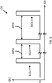
Figure 3 is an example plot of the variation of the current on the two wire interface with time, showing three different velocity measurements; -
Figure 4 shows one of the velocity measurements shown inFigure 3 , in more detail. -
Figure 1 shows a schematic illustration of a channel 1 carrying a flowingmedia 3, such as water. Aflow measurement device 11 is positioned in the channel 1, above the water surface 7, to measure the flow rate of thewater 3. Theflow measurement device 11 includes alevel measurement device 15, and avelocity measurement device 17. - The
level measurement device 15 emits ultrasound waves, receives reflections from the water surface 7, and, based on the time of flight, determines the distance from thelevel measurement device 15 to the water surface 7. Using the known distance from thelevel measurement device 15 to thebase 5 of the channel 1, the depth of the water can be determined. - Similarly, the
velocity measurement device 17 uses reflections of waves from the water surface 7 to determine the velocity of thewater 3 in the channel 1. - The
level measurement device 15 andvelocity measurement device 17 pass the determined depth and velocity to acontroller 13, which uses these variables to determine the flow. -
Figure 2 shows an example of avelocity measurement device 17 that uses Doppler radar to determine the velocity of thewater 3. Thevelocity measurement device 17 is split into two separate units, anexternal control unit 19 and aradar unit 21. Theexternal control unit 19 includes abattery 35 for powering thevelocity measurement device 17, and acontroller 37 for controlling operation of thevelocity measurement device 17. Theradar unit 21 includes a radar module 33 for transmitting and receiving microwaves, and determining the velocity based on the Doppler shift of the reflections. - The radar module 33 may be any suitable radar means for carrying out Doppler radar velocity measurements, and may include one or more microwave transmitters, and receivers, and processing means to determine the velocity based on the time of flight of the reflections from the water.
- The
external control unit 19 andradar unit 21 are coupled by a two wire interface 23 (also called a two wire loop). The twowire interface 23 is used to transfer power from theexternal control unit 19 to theradar unit 21, and for data transfer between theexternal control unit 19 and theradar unit 21. In at least some embodiments, use of the two wire interface for power transfer and data transfer provides a simple, lightweight and small unit that can be permanently installed in confined spaces, or used as part of a portable apparatus. - In use, the
external control unit 19 behaves as a master, and controls the operation of theradar unit 21, as a slave. In particular, theexternal control unit 19 controls when theradar unit 21 takes a measurement of the velocity. The operation of theexternal control unit 19, and hence thevelocity measurement device 17 as a whole is managed by the externalcontrol unit controller 37. - Between measurements, the
radar unit 21 and twowire interface 23 are deactivated, so no energy is transferred over the twowire interface 23. Theexternal control unit 19 is also arranged to minimise its power consumption between measurements. This ensures energy losses between measurements are minimised. -
Figure 3 shows an example of the current 100 on the twowire interface 23 over a period incorporating threeseparate velocity measurements velocity measurements 102 can be fixed, or variable, and can be based on a number of factors, including: user input, and/or a default time, and/or the previous level over water in the channel 1 or in a sump or well (not shown) the channel 1 flows into or out of and/or the previously measured flows. - For example, the
first measurement 102a may determine a relatively fast flow rate for water flowing into a nearly full sump. Therefore, thetime 104a between thefirst measurement 102a and thesecond measurement 102b may be set relatively short, as there is a risk of the sump overflowing and so regular monitoring is required. However, thesecond measurement 102b may determine that the flow rate has slowed, and so the time between thesecond measurement 102b and thethird measurement 102c may be set relatively long. - The time 104 between
measurements 102 can be any suitable value, and may be of the order of a few seconds, a few minutes, a few hours, or any time in between or longer. - As can be seen, between the
measurements 102, the current on the twowire interface 23 is 0 milliamps. Once the externalcontrol unit controller 37 determines that it is time to take a measurement, the twowire interface 23 activates.Figure 4 shows the current during a measurement (or active period) 102 in more detail. The current can be any value between 0 milliamps and a maximum 106a of 25 milliamps. The period when the two-wire interface 23 is active is divided into a first portion in which the measurement occurs, and a second portion in which data transfer occurs. In the second portion, currents between alower boundary 106c of 4 milliamps and anupper boundary 106b of 20 milliamps are used to communicate information over theinterface 23. - At the start of the active period, the current is set, by the
external control unit 19, to afirst value 116, outside thecommunication range 106b,c, such as 22 milliamps. Theradar unit 21 includes asecond controller 31. Theradar unit controller 31 detects the current 116 and determines that an active period has started. - The equipment of the Doppler radar module 33 requires a higher power level than can be delivered over the two
wire interface 23. This means that the radar module 33 cannot be directly powered over the twowire interface 23. Therefore, theradar unit 21 includes anenergy store 29 which is used to power the radar module 33. Theenergy store 29 is charged for longer than the radar module 33 is used for. This means that theenergy store 29 has more energy than is delivered over the twowire interface 23 during the period the radar module 33 is operated for, and so can deliver higher power to the radar module 33 than the twowire interface 23 during use. The use of theenergy store 29 means that in at least some embodiments, high power Doppler radar equipment to be used, but the flow measurement device remains low power overall. - At the start of the
active period 102, theradar unit controller 31 determines how much energy is in theenergy store 29, and determines how much energy can be used by the radar module 33, whilst still leaving sufficient energy to repeat the same measurement, without the energy store being replenished. - The
radar unit controller 31 then controls theradar unit 21 to take measurements of the velocity. Each measurement may include several individual readings of the velocity by emitting a wave a detecting the reflection, and the radar module 33 is active for the period the reading is taken for. Each reading lasts for a short duration, due to the time of flight for waves to reflect from the water surface 7. - The number of waves/reflections used in a reading (controlled by the duration of each reading), the output power in the radar waves, the number of repeat readings, the interval between repeat reading and the number of transmitter and receivers used can be controlled based on the energy in the
energy store 29. Generally, the more waves/reflections, longer measurement duration and higher power, the more accurate (and hence higher quality) the measurement, but the more power is consumed. In at least some embodiments, control of the different properties of the measurements means that energy in theenergy store 29 is used in an efficient manner. - By the end of the first portion of the
active period 102, the velocity measurements are complete. For the duration of the second portion, the current is set to asecond value 118, within the communication range. The second current 118 is proportional to the determined velocity. Theradar unit 21 includes acommunication module 25, which converts the determined velocity into the second current 118. Similarly, theexternal control unit 19 includes acommunication module 27, which reconverts the current back to the velocity for use in theexternal control unit 19. - After the end of the second portion, the two-
wire interface 23 is deactivated, and the current returns to 0 milliamps. - Measurement occurs in the first portion of the
active period 102, and communication in the second portion. Over both portions, the current on the two-wire interface 23 is also used to charge theenergy store 29, such that it is not depleted over continuous use. - The
length 110 of the first portion of the active period is between 4 and 5 seconds. This provides sufficient time for measurements and charging. Typically, the measurements may only take a few milliseconds, over the course of first portion. The second portion is a small fraction of a second in length. For example, the second portion is a few milliseconds in length. - The current in the
communication range 106b,c is calibrated depending on the physical characteristics of the channel 1, so that the lowest possible velocity in the channel is transferred by a second current 118 of 4 milliamps, and the fastest possible velocity is transferred by a second current 118 of 20 milliamps. In this way, the same device can be used in different channels 1, and still provide high resolution. - If the
radar unit controller 31 determines that no measurement is possible due to insufficient charge in theenergy store 29, then theradar unit controller 31 skips the measurement, and uses the first portion of theactive period 102 for charging only. In the second portion of theactive period 102, the twowire interface 23 may also be used to transfer an error code. This may be in the case that the velocity measurement was not possible due to system malfunction, or insufficient charge in theenergy store 29. - The external
control unit controller 37 may be arranged to determine patterns in the error codes. For example, if error codes occur every other measurement, theexternal control unit 19 may determine that insufficient energy is getting into theenergy store 29, and increase the duration of the first portion, or activate the twowire interface 23 for a charging period to provide further charge into theenergy store 29. Alternatively, for a number of consecutive error codes, theexternal control unit 19 may determine a system malfunction. - The error code is transferred by a current set outside the
communication range 106b,c. For example, the firstcurrent level 116 may be used as an error code. Different current levels may also be used for different error codes. For example, the first current 116 may be used to indicate insufficient charge, and a second current (for example 25 milliamps, may be used to indicate other errors. - The
external control unit 19 can also be used to provide configuration and setup commands to theradar unit 21 prior to use. For example, the length of the first potion of theactive period 102 may be set, and the communication range may be calibrated. This can be done by modulation of the current over the two-wire interface 23. The modulation can be encoded and decoded by thecontrollers radar unit 21 andexternal control unit 19. During operation when the setup and configuration is being carried, out, the current on the twowire interface 23 can provide additional charging. - The
radar unit 21 includes a small non-volatilelower power memory 39. This is a 4 kilobyte non-volatile memory that is used to store the velocity determined in at least the most recent measurement. The memory may also store other related information, and more than the single most recent measurement. Thememory 39 can be read over the twowire interface 23. At the end of the active period, the memory is updated and/or overwritten with the new velocity reading. - The operation described above ensures that the
battery 35 in theexternal control unit 19 is used in an efficient manner, and the battery life may be extended to years in length, whilst still allowing the most accurate possible readings. - The
external control unit 19 may be provided separately to theradar unit 21. Theexternal control unit 19 may be any suitable device that uses the same communication protocols as theradar unit 21. For example, theexternal control unit 19 may be any handheld or portable computer (not shown). Furthermore, theradar unit 21 may be used interchangeably with any suitableexternal control unit 19. The protocols may be provided separately, so any existing computer may be used as theexternal control unit 19. - In some examples, the
external control unit 19 may be part of acontroller 13 for aflow measurement device 11, or theexternal control unit 19 may be incorporated into thecontroller 13 for aflow measurement device 11. In this case, the velocity measurement is used to determine the flow. - It will be appreciated that the timings discussed above given are by way of example only, and any suitable timings may be used. The lengths of the
respective portions active period 108 should be sufficient to ensure readings can be taken, the results communicated and charge is transferred to theenergy store 29. - In the example discussed above, the active period is of fixed
length 110. Alternatively, theactive period length 110 may be variable. Theactive period length 110 may be varied on a similar basis to the gap between measurements, for example, user input, previous measurements and the like. In other examples, theactive period length 110 may vary following a predefined pattern. - The currents given above are also only given by way of example only, and any suitable ranges may be used. Furthermore, in the above examples, only currents above the maximum in the
communication range 106b, and below the overall maximum 106a for the twowire interface 23 are used. However, currents below the minimum in thecommunication range 106c, and above 0 milliamps could also be used. Furthermore, in some examples, the current may be at or below the maximum in thecommunication range 106b for charging. - It will also be appreciated that separate charging windows, where no measurements are made, may be included as a matter of course, rather than in response to error messages, although this is optional.
- The
radar unit controller 31 may use different criteria for determining how much energy from theenergy store 29 can be used. For example, it may determine the useable energy in theenergy store 29 such that only the minimum accuracy measurement can be repeated without further charging, or it may leave a preset amount of energy in theenergy store 29. Alternatively, it may try to use all of the energy in theenergy store 29, without leaving any in reserve. - Furthermore, the
radar unit controller 31 may be arranged to control the time 104 between measurements, based on the amount of energy in theenergy store 29. - In the above description, the current on the two
wire interface 23 is modulated to provide setup and configuration commands. It will be appreciated that any suitable communication protocol may be used instead. For example, the absolute value of the current may be set to different levels. Similarly, any suitable protocol may be used to communicate the measured velocity. - The battery may be any suitable type of power supply, and may be rechargeable.
- The
memory 39 may be any suitable non-volatile memory. In the above example, thememory 39 is a 4 kilobyte memory. However, thememory 39 may be any suitable size, down to 16 bit. The amount of past information stored in thememory 39 will vary in dependence on the size of thememory 39. - Where the
velocity measurement device 17 is used for determining a flow, any suitablelevel measurement device 15 can be used. The level measurement device may be powered from thesame battery 35 as thevelocity measurement device 17, or a different battery (not shown). Thelevel measurement device 15 may use a similar two wire loop, with similar control to the velocity measurement device, or not. The twomeasurement devices - The
velocity measurement device 17 may be provided on its own, without incorporation in aflow measurement device 11. Theflow measurement device 11 and/orvelocity measurement device 17 are for use with any type of media, such as, but not limited to, fluids and solids. - The
controller
Claims (15)
- A velocity measurement device (17) for measuring the velocity of a moving media (3) in a channel (1), the velocity measurement device (17) including a radar unit (21) having:a radar module (33) arranged to measure the velocity of the media (3) using the Doppler effect;a two wire interface (23) to the radar unit (21) arranged to receive power from an external power source, and provide data transfer between the radar unit (21) and an external control unit (19);an energy store (29) arranged to:receive energy available on the two wire interface (23) to charge the energy store (29);store the received energy; andsupply the stored energy to the radar module (33) when a velocity measurement is performed; anda radar unit controller (31) arranged to, during an active period (102) of the device (17): control the radar module (33) to take one or more readings of the velocity of the media (3) to provide a measurement of the velocity; and control operation of the radar unit (21) to store the energy received over the two wire interface (23) in the energy store (29),
wherein the two wire interface (23) is inactive between active periods (102) of the device (17), such that no power is delivered to the radar unit (21) between active periods (102). - The velocity measurement device (17) of claim 1, wherein the power delivered over the two wire interface (23) during a reading is insufficient to power the radar module (33) directly, and the energy stored in the energy store (29) over the active period (102) is sufficient to power the one or more readings.
- The velocity measurement device (17) of claim 1 or claim 2, wherein the radar module (33) is arranged to measure the velocity of the moving media (3) within the active period (102) of the device (17),
wherein the active period (102) is divided into a first portion (110) in which the velocity of the media (3) is measured, and a second portion (112) in which the measured velocity is communicated to the external control unit (19), and
wherein the energy store (29) is charged during at least the first portion (110) of the active period (102). - The velocity measurement device (17) of any preceding claim, wherein the radar unit controller (31) is further arranged to:determine the energy stored in the energy store (29);determine the proportion of the energy that can be used in a velocity measurement; andcontrol the radar module (33) to measure the velocity based on the determined portion of the energy that can be used.
- The velocity measurement device (17) of claim 4, wherein the radar unit controller (31) is arranged to vary one or more of: an output power of the radar module (33); a measurement duration; a number of readings in the active period (102); an interval between readings in the active period (102); and a number of individual transmitters and/or receivers used based on the determined portion of the energy that can be used.
- The velocity measurement device (17) of claim 4 or claim 5, wherein the radar unit controller (31) is arranged to leave a minimum level of energy in the energy store (29), such that the measurement can be repeated in a subsequent active period (102) without the energy store (29) being replenished.
- The velocity measurement device (17) of claim 6, wherein the radar unit controller (31) is arranged to:omit a velocity measurement if it is determined that the energy store (29) does not have sufficient energy to power the radar module (33) and leave the minimum level of energy in the energy store (29); andonly charge the energy store (29) during the active period (102).
- The velocity measurement device (17) of any preceding claim, including:an external control unit (19) arranged to:control operation of the radar unit (21); andcommunicate with the radar unit (21) over the two wire interface (23); anda power supply for providing power to the radar unit (21) over the two wire interface (23), and powering operation of the external control unit (19).
- The velocity measurement device (17) of claim 8, wherein:the external control unit (19) is arranged to control the operation of the radar unit (21) such that the velocity is measured intermittently; andthe external control unit (19) is arranged to deactivate the two wire interface (23) between velocity measurements.
- The velocity measurement device (17) of any preceding claim, wherein:the two wire interface (23) is arranged to carry a maximum current;the current on the two wire interface (23) is varied between a first current and a second current, both lower than the maximum current, to transfer data between the external control unit (19) and the radar unit (21); andthe current on the two wire interface (23) is higher than the second current when charging the energy store (29).
- A flow measurement device (11) for measuring the flow rate of a moving media (3) in a channel (1), the flow measurement device (11) including:a level measurement device (15) for determining the level of the moving media (3) in the channel (1); anda velocity measurement device (17) according to any of claims 1 to 10,for measuring the velocity of the moving media (3) in the channel (1), wherein the flow measurement device (11) is arranged to determine the flow based on the measured level and the measured velocity.
- A method of measuring the velocity of a moving media (3) in a channel (1), the method including:activating a two wire interface (23) to supply power from an external power source to a radar unit (21);at the radar unit, receiving power over the two wire interface (23);storing energy received on the two wire interface (23) in an energy store (29) of the radar unit (21);with a radar module (33) of the radar unit (21), measuring the velocity of the media (3) in the channel (1) using the Doppler effect by taking one or more readings of the velocity of the media (3) during an active period (102) of the two wire interface (23), wherein stored energy from the energy store (29) is supplied to the radar module (33) when a velocity measurement is performed;transferring the measured velocity to an external control unit (19) over the two wire interface (23); anddeactivating the two wire interface (23) between active periods (102), such that no power is delivered to the radar unit (21).
- The method of claim 12, wherein the power delivered over the two wire interface (23) during a reading is insufficient to power the radar module (33) directly, and the energy stored in the energy store (29) over the active period (102) is sufficient to power the radar module (33).
- A method of measuring the flow of a moving media (3) in a channel (1), the method including:measuring the level of media (3) in the channel (1);measuring the velocity of the media (3) in the channel (1) according to the method of claim 12 or claim 13; anddetermining the flow based on the measured level and the measured velocity.
- A machine readable medium having instructions to cause the device (17) according to claims 1 to 10 to execute the steps of the method of claim 12 or claim 13 or cause the device (11) according to claim 11 to execute the method of claim 14.
Applications Claiming Priority (1)
| Application Number | Priority Date | Filing Date | Title |
|---|---|---|---|
| GB1600604.1A GB2546282B (en) | 2016-01-13 | 2016-01-13 | Doppler radar flow measurement |
Publications (2)
| Publication Number | Publication Date |
|---|---|
| EP3193175A1 EP3193175A1 (en) | 2017-07-19 |
| EP3193175B1 true EP3193175B1 (en) | 2020-03-11 |
Family
ID=55445951
Family Applications (1)
| Application Number | Title | Priority Date | Filing Date |
|---|---|---|---|
| EP17150546.4A Active EP3193175B1 (en) | 2016-01-13 | 2017-01-06 | Doppler flow radar |
Country Status (3)
| Country | Link |
|---|---|
| US (1) | US10571319B2 (en) |
| EP (1) | EP3193175B1 (en) |
| GB (1) | GB2546282B (en) |
Families Citing this family (7)
| Publication number | Priority date | Publication date | Assignee | Title |
|---|---|---|---|---|
| EP3575816B1 (en) * | 2018-05-30 | 2021-06-30 | VEGA Grieshaber KG | Device for measuring the flow velocity of a medium |
| DE102018117175A1 (en) * | 2018-07-16 | 2020-01-16 | Vega Grieshaber Kg | Connection device between field device and on-site display |
| CN109764935A (en) * | 2018-12-26 | 2019-05-17 | 南京渤溢电子科技有限公司 | A radar wave automatic current measuring robot |
| EP3754309B1 (en) * | 2019-06-19 | 2023-03-29 | Rosemount Tank Radar AB | Radar level gauging with power-dependent number of measurement operations |
| DE102021206489A1 (en) * | 2021-06-23 | 2022-12-29 | Robert Bosch Gesellschaft mit beschränkter Haftung | Procedure and sensor bus system |
| JP2024538562A (en) * | 2021-09-24 | 2024-10-23 | ハイドロ レーダー,エルエルシー | Flow and level monitors for fluid systems |
| GB2618304A (en) * | 2022-02-09 | 2023-11-08 | Pulsar Process Measurement Ltd | Apparatus for in situ level and flow measurement |
Family Cites Families (18)
| Publication number | Priority date | Publication date | Assignee | Title |
|---|---|---|---|---|
| US6014100A (en) * | 1998-02-27 | 2000-01-11 | Vega Grieshaber Kg | Two-wire RADAR sensor with intermittently operating circuitry components |
| US6535161B1 (en) * | 2000-11-28 | 2003-03-18 | Mcewan Technologies, Llc | Loop powered radar rangefinder |
| DE10254054A1 (en) * | 2002-11-19 | 2004-06-03 | Endress + Hauser Flowtec Ag, Reinach | Device for determining and / or monitoring the volume and / or mass flow of a medium |
| EP1562051B1 (en) | 2004-02-04 | 2012-08-29 | VEGA Grieshaber KG | Method for determining a level of material with a two-wire radar sensor |
| WO2005080923A1 (en) * | 2004-02-13 | 2005-09-01 | Combustion Dynamics Corp. | Flow meter |
| DE102008036963A1 (en) * | 2008-08-08 | 2010-02-18 | Endress + Hauser Gmbh + Co. Kg | Device for determining and / or monitoring the level and / or the flow of a medium |
| US7952514B2 (en) * | 2008-11-20 | 2011-05-31 | Rosemount Tank Radar Ab | Energy storage unit for a radar level gauge system |
| US8125849B2 (en) * | 2008-12-19 | 2012-02-28 | Ysi Incorporated | Integrated multi-beam acoustic doppler discharge measurement system |
| US8160725B2 (en) * | 2009-05-20 | 2012-04-17 | Vega Grieshaber Kg | Energy saving control for a field device |
| US8215183B2 (en) * | 2009-07-03 | 2012-07-10 | Ads Llc | Augmented surface sensor for measuring flow velocity |
| US8464594B2 (en) * | 2010-03-05 | 2013-06-18 | Applied Materials, Inc. | Measuring flow properties of multiple gas nozzles of a gas distributor |
| US8477064B2 (en) * | 2010-12-22 | 2013-07-02 | Rosemount Tank Radar Ab | Loop-powered field device |
| DE102013213345A1 (en) * | 2013-07-08 | 2015-01-08 | Vega Grieshaber Kg | Universal data acquisition in waters |
| DE102013213346A1 (en) * | 2013-07-08 | 2015-01-08 | Vega Grieshaber Kg | Determination of level and flow rate of a medium |
| US10254145B2 (en) * | 2014-02-21 | 2019-04-09 | Vega Grieshaber Kg | Level indicator featuring optimized energy supply |
| US9389113B2 (en) * | 2014-03-05 | 2016-07-12 | Rosemount Tank Radar Ab | Low power radar level gauge system |
| US9395229B2 (en) * | 2014-03-05 | 2016-07-19 | Rosemount Tank Radar Ab | Low power radar level gauge system with integrated microwave circuit |
| US9541444B2 (en) * | 2014-04-01 | 2017-01-10 | Rosemount Tank Radar Ab | Self-diagnosing FMCW radar level gauge |
-
2016
- 2016-01-13 GB GB1600604.1A patent/GB2546282B/en active Active
-
2017
- 2017-01-06 US US15/399,957 patent/US10571319B2/en active Active
- 2017-01-06 EP EP17150546.4A patent/EP3193175B1/en active Active
Non-Patent Citations (1)
| Title |
|---|
| None * |
Also Published As
| Publication number | Publication date |
|---|---|
| US20170199066A1 (en) | 2017-07-13 |
| US10571319B2 (en) | 2020-02-25 |
| GB2546282B (en) | 2019-01-23 |
| GB201600604D0 (en) | 2016-02-24 |
| GB2546282A (en) | 2017-07-19 |
| EP3193175A1 (en) | 2017-07-19 |
Similar Documents
| Publication | Publication Date | Title |
|---|---|---|
| US10571319B2 (en) | Doppler flow radar | |
| US6014100A (en) | Two-wire RADAR sensor with intermittently operating circuitry components | |
| EP2677339B1 (en) | Pulsed level gauge system with adaptive transceiver control | |
| RU2582894C2 (en) | Radar measurement of level with determination of surface displacement | |
| CN109477859B (en) | Electric energy metering equipment | |
| EP2656023B1 (en) | Loop-powered field device | |
| KR20110110987A (en) | Wireless power transfer control method and apparatus | |
| US9218736B2 (en) | Sensor nodes, apparatuses, and methods for wirelessly transmitting data to a power infrastructure | |
| CN104198016A (en) | Ultrasonic liquid level gauge and ultrasonic liquid level detecting method | |
| EP2677285A2 (en) | Intermittent filling level determination with dynamically determined number of measurements | |
| KR102113856B1 (en) | Level indicator featuring optimized energy supply | |
| CN105277320A (en) | Liquid leakage detection sensor and system | |
| EP3298470A1 (en) | Loop-powered field device with voltage regulator and current source in series | |
| CN108072423A (en) | Radar levelmeter and correlation technique | |
| KR20170073525A (en) | Contactless power transfer system and method for controlling the same | |
| Chinaeke-Ogbuka et al. | A microcontroller-based water level indicator using radio frequency (rf) technology and ultrasonic sensor | |
| US11536595B2 (en) | Dual sensor | |
| US11048009B2 (en) | Programmable universal probe | |
| EP4239368B1 (en) | Appraratus for in situ level and flow measurement | |
| KR101742591B1 (en) | Method and Apparatus to Control Wireless Power Transform | |
| CN116667888B (en) | Very low frequency electromagnetic signal transmitter | |
| CN108872996B (en) | Distance measuring equipment and unmanned aerial vehicle | |
| Ajibo | A Microcontroller-Based Water Level Indicator using Radio Frequency (RF) Technology and Ultrasonic Sensor | |
| HK1261894A1 (en) | Electricity metering device | |
| CN120916054A (en) | TOF camera and ranging method based on TOF camera |
Legal Events
| Date | Code | Title | Description |
|---|---|---|---|
| PUAI | Public reference made under article 153(3) epc to a published international application that has entered the european phase |
Free format text: ORIGINAL CODE: 0009012 |
|
| STAA | Information on the status of an ep patent application or granted ep patent |
Free format text: STATUS: THE APPLICATION HAS BEEN PUBLISHED |
|
| AK | Designated contracting states |
Kind code of ref document: A1 Designated state(s): AL AT BE BG CH CY CZ DE DK EE ES FI FR GB GR HR HU IE IS IT LI LT LU LV MC MK MT NL NO PL PT RO RS SE SI SK SM TR |
|
| AX | Request for extension of the european patent |
Extension state: BA ME |
|
| STAA | Information on the status of an ep patent application or granted ep patent |
Free format text: STATUS: REQUEST FOR EXAMINATION WAS MADE |
|
| 17P | Request for examination filed |
Effective date: 20171019 |
|
| RBV | Designated contracting states (corrected) |
Designated state(s): AL AT BE BG CH CY CZ DE DK EE ES FI FR GB GR HR HU IE IS IT LI LT LU LV MC MK MT NL NO PL PT RO RS SE SI SK SM TR |
|
| STAA | Information on the status of an ep patent application or granted ep patent |
Free format text: STATUS: EXAMINATION IS IN PROGRESS |
|
| 17Q | First examination report despatched |
Effective date: 20181204 |
|
| RIC1 | Information provided on ipc code assigned before grant |
Ipc: G01F 23/296 20060101ALN20190510BHEP Ipc: G01S 7/28 20060101ALI20190510BHEP Ipc: G01S 13/88 20060101ALI20190510BHEP Ipc: G01P 5/24 20060101AFI20190510BHEP Ipc: G01S 13/58 20060101ALI20190510BHEP Ipc: G01S 13/86 20060101ALI20190510BHEP Ipc: G06F 13/42 20060101ALI20190510BHEP |
|
| GRAP | Despatch of communication of intention to grant a patent |
Free format text: ORIGINAL CODE: EPIDOSNIGR1 |
|
| STAA | Information on the status of an ep patent application or granted ep patent |
Free format text: STATUS: GRANT OF PATENT IS INTENDED |
|
| RIC1 | Information provided on ipc code assigned before grant |
Ipc: G01S 13/86 20060101ALI20190606BHEP Ipc: G01S 7/28 20060101ALI20190606BHEP Ipc: G06F 13/42 20060101ALI20190606BHEP Ipc: G01S 13/88 20060101ALI20190606BHEP Ipc: G01P 5/24 20060101AFI20190606BHEP Ipc: G01S 13/58 20060101ALI20190606BHEP Ipc: G01F 23/296 20060101ALN20190606BHEP |
|
| INTG | Intention to grant announced |
Effective date: 20190710 |
|
| GRAJ | Information related to disapproval of communication of intention to grant by the applicant or resumption of examination proceedings by the epo deleted |
Free format text: ORIGINAL CODE: EPIDOSDIGR1 |
|
| STAA | Information on the status of an ep patent application or granted ep patent |
Free format text: STATUS: EXAMINATION IS IN PROGRESS |
|
| GRAP | Despatch of communication of intention to grant a patent |
Free format text: ORIGINAL CODE: EPIDOSNIGR1 |
|
| STAA | Information on the status of an ep patent application or granted ep patent |
Free format text: STATUS: GRANT OF PATENT IS INTENDED |
|
| INTC | Intention to grant announced (deleted) | ||
| RBV | Designated contracting states (corrected) |
Designated state(s): AL AT BE BG CH CY CZ DE DK EE ES FI FR GR HR HU IE IS IT LI LT LU LV MC MK MT NL NO PL PT RO RS SE SI SK SM TR |
|
| RIC1 | Information provided on ipc code assigned before grant |
Ipc: G06F 13/42 20060101ALI20190909BHEP Ipc: G01S 13/86 20060101ALI20190909BHEP Ipc: G01F 23/296 20060101ALN20190909BHEP Ipc: G01S 7/28 20060101ALI20190909BHEP Ipc: G01S 13/88 20060101ALI20190909BHEP Ipc: G01P 5/24 20060101AFI20190909BHEP Ipc: G01S 13/58 20060101ALI20190909BHEP |
|
| INTG | Intention to grant announced |
Effective date: 20190924 |
|
| GRAS | Grant fee paid |
Free format text: ORIGINAL CODE: EPIDOSNIGR3 |
|
| GRAA | (expected) grant |
Free format text: ORIGINAL CODE: 0009210 |
|
| STAA | Information on the status of an ep patent application or granted ep patent |
Free format text: STATUS: THE PATENT HAS BEEN GRANTED |
|
| AK | Designated contracting states |
Kind code of ref document: B1 Designated state(s): AL AT BE BG CH CY CZ DE DK EE ES FI FR GR HR HU IE IS IT LI LT LU LV MC MK MT NL NO PL PT RO RS SE SI SK SM TR |
|
| REG | Reference to a national code |
Ref country code: CH Ref legal event code: EP |
|
| REG | Reference to a national code |
Ref country code: AT Ref legal event code: REF Ref document number: 1243804 Country of ref document: AT Kind code of ref document: T Effective date: 20200315 |
|
| REG | Reference to a national code |
Ref country code: IE Ref legal event code: FG4D |
|
| REG | Reference to a national code |
Ref country code: DE Ref legal event code: R096 Ref document number: 602017012744 Country of ref document: DE |
|
| PG25 | Lapsed in a contracting state [announced via postgrant information from national office to epo] |
Ref country code: RS Free format text: LAPSE BECAUSE OF FAILURE TO SUBMIT A TRANSLATION OF THE DESCRIPTION OR TO PAY THE FEE WITHIN THE PRESCRIBED TIME-LIMIT Effective date: 20200311 Ref country code: NO Free format text: LAPSE BECAUSE OF FAILURE TO SUBMIT A TRANSLATION OF THE DESCRIPTION OR TO PAY THE FEE WITHIN THE PRESCRIBED TIME-LIMIT Effective date: 20200611 Ref country code: FI Free format text: LAPSE BECAUSE OF FAILURE TO SUBMIT A TRANSLATION OF THE DESCRIPTION OR TO PAY THE FEE WITHIN THE PRESCRIBED TIME-LIMIT Effective date: 20200311 |
|
| REG | Reference to a national code |
Ref country code: NL Ref legal event code: MP Effective date: 20200311 |
|
| PG25 | Lapsed in a contracting state [announced via postgrant information from national office to epo] |
Ref country code: BG Free format text: LAPSE BECAUSE OF FAILURE TO SUBMIT A TRANSLATION OF THE DESCRIPTION OR TO PAY THE FEE WITHIN THE PRESCRIBED TIME-LIMIT Effective date: 20200611 Ref country code: HR Free format text: LAPSE BECAUSE OF FAILURE TO SUBMIT A TRANSLATION OF THE DESCRIPTION OR TO PAY THE FEE WITHIN THE PRESCRIBED TIME-LIMIT Effective date: 20200311 Ref country code: GR Free format text: LAPSE BECAUSE OF FAILURE TO SUBMIT A TRANSLATION OF THE DESCRIPTION OR TO PAY THE FEE WITHIN THE PRESCRIBED TIME-LIMIT Effective date: 20200612 Ref country code: LV Free format text: LAPSE BECAUSE OF FAILURE TO SUBMIT A TRANSLATION OF THE DESCRIPTION OR TO PAY THE FEE WITHIN THE PRESCRIBED TIME-LIMIT Effective date: 20200311 Ref country code: SE Free format text: LAPSE BECAUSE OF FAILURE TO SUBMIT A TRANSLATION OF THE DESCRIPTION OR TO PAY THE FEE WITHIN THE PRESCRIBED TIME-LIMIT Effective date: 20200311 |
|
| REG | Reference to a national code |
Ref country code: LT Ref legal event code: MG4D |
|
| PG25 | Lapsed in a contracting state [announced via postgrant information from national office to epo] |
Ref country code: NL Free format text: LAPSE BECAUSE OF FAILURE TO SUBMIT A TRANSLATION OF THE DESCRIPTION OR TO PAY THE FEE WITHIN THE PRESCRIBED TIME-LIMIT Effective date: 20200311 |
|
| PG25 | Lapsed in a contracting state [announced via postgrant information from national office to epo] |
Ref country code: IS Free format text: LAPSE BECAUSE OF FAILURE TO SUBMIT A TRANSLATION OF THE DESCRIPTION OR TO PAY THE FEE WITHIN THE PRESCRIBED TIME-LIMIT Effective date: 20200711 Ref country code: SK Free format text: LAPSE BECAUSE OF FAILURE TO SUBMIT A TRANSLATION OF THE DESCRIPTION OR TO PAY THE FEE WITHIN THE PRESCRIBED TIME-LIMIT Effective date: 20200311 Ref country code: PT Free format text: LAPSE BECAUSE OF FAILURE TO SUBMIT A TRANSLATION OF THE DESCRIPTION OR TO PAY THE FEE WITHIN THE PRESCRIBED TIME-LIMIT Effective date: 20200805 Ref country code: LT Free format text: LAPSE BECAUSE OF FAILURE TO SUBMIT A TRANSLATION OF THE DESCRIPTION OR TO PAY THE FEE WITHIN THE PRESCRIBED TIME-LIMIT Effective date: 20200311 Ref country code: CZ Free format text: LAPSE BECAUSE OF FAILURE TO SUBMIT A TRANSLATION OF THE DESCRIPTION OR TO PAY THE FEE WITHIN THE PRESCRIBED TIME-LIMIT Effective date: 20200311 Ref country code: RO Free format text: LAPSE BECAUSE OF FAILURE TO SUBMIT A TRANSLATION OF THE DESCRIPTION OR TO PAY THE FEE WITHIN THE PRESCRIBED TIME-LIMIT Effective date: 20200311 Ref country code: SM Free format text: LAPSE BECAUSE OF FAILURE TO SUBMIT A TRANSLATION OF THE DESCRIPTION OR TO PAY THE FEE WITHIN THE PRESCRIBED TIME-LIMIT Effective date: 20200311 Ref country code: EE Free format text: LAPSE BECAUSE OF FAILURE TO SUBMIT A TRANSLATION OF THE DESCRIPTION OR TO PAY THE FEE WITHIN THE PRESCRIBED TIME-LIMIT Effective date: 20200311 |
|
| REG | Reference to a national code |
Ref country code: AT Ref legal event code: MK05 Ref document number: 1243804 Country of ref document: AT Kind code of ref document: T Effective date: 20200311 |
|
| REG | Reference to a national code |
Ref country code: DE Ref legal event code: R097 Ref document number: 602017012744 Country of ref document: DE |
|
| PLBE | No opposition filed within time limit |
Free format text: ORIGINAL CODE: 0009261 |
|
| STAA | Information on the status of an ep patent application or granted ep patent |
Free format text: STATUS: NO OPPOSITION FILED WITHIN TIME LIMIT |
|
| PG25 | Lapsed in a contracting state [announced via postgrant information from national office to epo] |
Ref country code: DK Free format text: LAPSE BECAUSE OF FAILURE TO SUBMIT A TRANSLATION OF THE DESCRIPTION OR TO PAY THE FEE WITHIN THE PRESCRIBED TIME-LIMIT Effective date: 20200311 Ref country code: AT Free format text: LAPSE BECAUSE OF FAILURE TO SUBMIT A TRANSLATION OF THE DESCRIPTION OR TO PAY THE FEE WITHIN THE PRESCRIBED TIME-LIMIT Effective date: 20200311 Ref country code: IT Free format text: LAPSE BECAUSE OF FAILURE TO SUBMIT A TRANSLATION OF THE DESCRIPTION OR TO PAY THE FEE WITHIN THE PRESCRIBED TIME-LIMIT Effective date: 20200311 Ref country code: ES Free format text: LAPSE BECAUSE OF FAILURE TO SUBMIT A TRANSLATION OF THE DESCRIPTION OR TO PAY THE FEE WITHIN THE PRESCRIBED TIME-LIMIT Effective date: 20200311 |
|
| 26N | No opposition filed |
Effective date: 20201214 |
|
| PG25 | Lapsed in a contracting state [announced via postgrant information from national office to epo] |
Ref country code: PL Free format text: LAPSE BECAUSE OF FAILURE TO SUBMIT A TRANSLATION OF THE DESCRIPTION OR TO PAY THE FEE WITHIN THE PRESCRIBED TIME-LIMIT Effective date: 20200311 Ref country code: SI Free format text: LAPSE BECAUSE OF FAILURE TO SUBMIT A TRANSLATION OF THE DESCRIPTION OR TO PAY THE FEE WITHIN THE PRESCRIBED TIME-LIMIT Effective date: 20200311 |
|
| PG25 | Lapsed in a contracting state [announced via postgrant information from national office to epo] |
Ref country code: MC Free format text: LAPSE BECAUSE OF FAILURE TO SUBMIT A TRANSLATION OF THE DESCRIPTION OR TO PAY THE FEE WITHIN THE PRESCRIBED TIME-LIMIT Effective date: 20200311 |
|
| REG | Reference to a national code |
Ref country code: CH Ref legal event code: PL |
|
| PG25 | Lapsed in a contracting state [announced via postgrant information from national office to epo] |
Ref country code: LU Free format text: LAPSE BECAUSE OF NON-PAYMENT OF DUE FEES Effective date: 20210106 |
|
| REG | Reference to a national code |
Ref country code: BE Ref legal event code: MM Effective date: 20210131 |
|
| PG25 | Lapsed in a contracting state [announced via postgrant information from national office to epo] |
Ref country code: LI Free format text: LAPSE BECAUSE OF NON-PAYMENT OF DUE FEES Effective date: 20210131 Ref country code: CH Free format text: LAPSE BECAUSE OF NON-PAYMENT OF DUE FEES Effective date: 20210131 |
|
| PG25 | Lapsed in a contracting state [announced via postgrant information from national office to epo] |
Ref country code: IE Free format text: LAPSE BECAUSE OF NON-PAYMENT OF DUE FEES Effective date: 20210106 |
|
| PG25 | Lapsed in a contracting state [announced via postgrant information from national office to epo] |
Ref country code: BE Free format text: LAPSE BECAUSE OF NON-PAYMENT OF DUE FEES Effective date: 20210131 |
|
| PG25 | Lapsed in a contracting state [announced via postgrant information from national office to epo] |
Ref country code: HU Free format text: LAPSE BECAUSE OF FAILURE TO SUBMIT A TRANSLATION OF THE DESCRIPTION OR TO PAY THE FEE WITHIN THE PRESCRIBED TIME-LIMIT; INVALID AB INITIO Effective date: 20170106 |
|
| PG25 | Lapsed in a contracting state [announced via postgrant information from national office to epo] |
Ref country code: CY Free format text: LAPSE BECAUSE OF FAILURE TO SUBMIT A TRANSLATION OF THE DESCRIPTION OR TO PAY THE FEE WITHIN THE PRESCRIBED TIME-LIMIT Effective date: 20200311 |
|
| PG25 | Lapsed in a contracting state [announced via postgrant information from national office to epo] |
Ref country code: MK Free format text: LAPSE BECAUSE OF FAILURE TO SUBMIT A TRANSLATION OF THE DESCRIPTION OR TO PAY THE FEE WITHIN THE PRESCRIBED TIME-LIMIT Effective date: 20200311 |
|
| PG25 | Lapsed in a contracting state [announced via postgrant information from national office to epo] |
Ref country code: MT Free format text: LAPSE BECAUSE OF FAILURE TO SUBMIT A TRANSLATION OF THE DESCRIPTION OR TO PAY THE FEE WITHIN THE PRESCRIBED TIME-LIMIT Effective date: 20200311 |
|
| PG25 | Lapsed in a contracting state [announced via postgrant information from national office to epo] |
Ref country code: TR Free format text: LAPSE BECAUSE OF FAILURE TO SUBMIT A TRANSLATION OF THE DESCRIPTION OR TO PAY THE FEE WITHIN THE PRESCRIBED TIME-LIMIT Effective date: 20200311 |
|
| PGFP | Annual fee paid to national office [announced via postgrant information from national office to epo] |
Ref country code: DE Payment date: 20260127 Year of fee payment: 10 |
|
| PGFP | Annual fee paid to national office [announced via postgrant information from national office to epo] |
Ref country code: FR Payment date: 20260126 Year of fee payment: 10 |