EP3193044A1 - Differential assembly with spider shaft retention - Google Patents
Differential assembly with spider shaft retention Download PDFInfo
- Publication number
- EP3193044A1 EP3193044A1 EP16195368.2A EP16195368A EP3193044A1 EP 3193044 A1 EP3193044 A1 EP 3193044A1 EP 16195368 A EP16195368 A EP 16195368A EP 3193044 A1 EP3193044 A1 EP 3193044A1
- Authority
- EP
- European Patent Office
- Prior art keywords
- spider shaft
- spider
- shaft
- differential assembly
- disposed
- Prior art date
- Legal status (The legal status is an assumption and is not a legal conclusion. Google has not performed a legal analysis and makes no representation as to the accuracy of the status listed.)
- Granted
Links
Images

Classifications
-
- F—MECHANICAL ENGINEERING; LIGHTING; HEATING; WEAPONS; BLASTING
- F16—ENGINEERING ELEMENTS AND UNITS; GENERAL MEASURES FOR PRODUCING AND MAINTAINING EFFECTIVE FUNCTIONING OF MACHINES OR INSTALLATIONS; THERMAL INSULATION IN GENERAL
- F16H—GEARING
- F16H48/00—Differential gearings
- F16H48/38—Constructional details
- F16H48/40—Constructional details characterised by features of the rotating cases
-
- F—MECHANICAL ENGINEERING; LIGHTING; HEATING; WEAPONS; BLASTING
- F16—ENGINEERING ELEMENTS AND UNITS; GENERAL MEASURES FOR PRODUCING AND MAINTAINING EFFECTIVE FUNCTIONING OF MACHINES OR INSTALLATIONS; THERMAL INSULATION IN GENERAL
- F16H—GEARING
- F16H48/00—Differential gearings
- F16H48/06—Differential gearings with gears having orbital motion
- F16H48/08—Differential gearings with gears having orbital motion comprising bevel gears
-
- F—MECHANICAL ENGINEERING; LIGHTING; HEATING; WEAPONS; BLASTING
- F16—ENGINEERING ELEMENTS AND UNITS; GENERAL MEASURES FOR PRODUCING AND MAINTAINING EFFECTIVE FUNCTIONING OF MACHINES OR INSTALLATIONS; THERMAL INSULATION IN GENERAL
- F16H—GEARING
- F16H57/00—General details of gearing
- F16H57/02—Gearboxes; Mounting gearing therein
- F16H57/021—Shaft support structures, e.g. partition walls, bearing eyes, casing walls or covers with bearings
-
- F—MECHANICAL ENGINEERING; LIGHTING; HEATING; WEAPONS; BLASTING
- F16—ENGINEERING ELEMENTS AND UNITS; GENERAL MEASURES FOR PRODUCING AND MAINTAINING EFFECTIVE FUNCTIONING OF MACHINES OR INSTALLATIONS; THERMAL INSULATION IN GENERAL
- F16H—GEARING
- F16H57/00—General details of gearing
- F16H57/02—Gearboxes; Mounting gearing therein
- F16H57/023—Mounting or installation of gears or shafts in the gearboxes, e.g. methods or means for assembly
-
- F—MECHANICAL ENGINEERING; LIGHTING; HEATING; WEAPONS; BLASTING
- F16—ENGINEERING ELEMENTS AND UNITS; GENERAL MEASURES FOR PRODUCING AND MAINTAINING EFFECTIVE FUNCTIONING OF MACHINES OR INSTALLATIONS; THERMAL INSULATION IN GENERAL
- F16H—GEARING
- F16H48/00—Differential gearings
- F16H48/06—Differential gearings with gears having orbital motion
- F16H48/08—Differential gearings with gears having orbital motion comprising bevel gears
- F16H2048/082—Differential gearings with gears having orbital motion comprising bevel gears characterised by the arrangement of output shafts
-
- F—MECHANICAL ENGINEERING; LIGHTING; HEATING; WEAPONS; BLASTING
- F16—ENGINEERING ELEMENTS AND UNITS; GENERAL MEASURES FOR PRODUCING AND MAINTAINING EFFECTIVE FUNCTIONING OF MACHINES OR INSTALLATIONS; THERMAL INSULATION IN GENERAL
- F16H—GEARING
- F16H48/00—Differential gearings
- F16H48/06—Differential gearings with gears having orbital motion
- F16H48/08—Differential gearings with gears having orbital motion comprising bevel gears
- F16H2048/085—Differential gearings with gears having orbital motion comprising bevel gears characterised by shafts or gear carriers for orbital gears
Definitions
- This disclosure relates to a differential assembly that has a case that is configured to retain shafts of a spider.
- a bevel gear differential is disclosed in United States Patent Publication No. 2015/0059180 .
- a differential assembly may include a case and a spider.
- the case may have a first case portion and a second case portion.
- the first case portion may have a first cavity, an outer surface, a spider shaft hole, and a recess.
- the outer surface may be disposed around the first cavity.
- the spider shaft hole may extend from the outer surface to the first cavity.
- the recess may be disposed between the outer surface and the first cavity and may extend from the spider shaft hole.
- the second case portion may be disposed on the first case portion.
- the second case portion may have a protrusion that may extend through the recess into the spider shaft hole.
- the spider may include a primary spider shaft and a secondary spider shaft.
- the primary spider shaft may be mounted to the first case portion.
- the secondary spider shaft may be received in the spider shaft hole and may extend between the spider shaft hole and the primary spider shaft.
- the secondary spider shaft may have a retaining groove that may receive the protrusion to retain the secondary spider shaft in the spider shaft
- a differential assembly may include a case and a spider.
- the case may rotate about an axis and may include a first case portion and a second case portion.
- the first case portion may have a first cavity, an outer surface, a set of spider shaft holes, and a recess.
- the first cavity may be disposed along the axis.
- the outer surface may extend around the first cavity.
- the set of spider shaft holes may be spaced apart from each other and may extend from the outer surface to the first cavity.
- the recess may be disposed between the outer surface and the first cavity and may extend from each member of the set of spider shaft holes.
- the second case portion may be disposed on the first case portion.
- the second case portion may have a second cavity and a protrusion.
- the second cavity may be disposed along the axis.
- the protrusion may extend through the recess into each member of the set of spider shaft holes.
- the spider may be at least partially disposed in the first cavity.
- the spider may include a primary spider shaft and a secondary spider shaft.
- the primary spider shaft may be received in first and second members of the set of spider shaft holes.
- the secondary spider shaft may be received in a third member of the set of spider shaft holes and may extend to the primary spider shaft.
- the secondary spider shaft may have a retaining groove that may receive the protrusion to retain the secondary spider shaft in the spider shaft hole.
- the differential assembly 10 may be configured for use with a vehicle, such as a motor vehicle like a truck, bus, farm equipment, military transport or weaponry vehicle, or cargo loading equipment for land, air, or marine vessels.
- a vehicle such as a motor vehicle like a truck, bus, farm equipment, military transport or weaponry vehicle, or cargo loading equipment for land, air, or marine vessels.
- the differential assembly 10 may be provided with a vehicle drivetrain component, such as an axle assembly or transfer case, or wheel hub assembly.
- the differential assembly 10 may be configured as an interaxle differential unit that may be provided with an axle assembly to compensate for speed differences between different axle assemblies that may be connected in series.
- the differential assembly 10 may also be provided with a wheel hub assembly that may rotatably support a vehicle wheel to provide gear reduction or gear ratio modification between a wheel axle and a traction wheel.
- the differential assembly 10 is described below primarily in the context of an axle assembly 12 and more specifically as a differential assembly 10 that may transmit torque to two wheel axles and their associated traction wheel assemblies and may permit the wheel axles and traction wheel assemblies to rotate at different velocities.
- the differential assembly 10 may facilitate the transfer of torque between components and/or allow components to rotate at different velocities.
- the axle assembly 12 may include a housing 20, a first shaft 22, and a second shaft 24.
- the housing 20 may receive the differential assembly 10 and various components of the axle assembly 12. In addition, the housing 20 may facilitate mounting of the axle assembly 12 to the vehicle. In Figure 4 , only a portion of the housing 20 is shown to more clearly illustrate the differential assembly 10.
- the first shaft 22 and the second shaft 24 may be at least partially disposed in the housing 20.
- the first shaft 22 and the second shaft 24 may be spaced apart from each other and may extend in opposite directions from the differential assembly 10.
- the first shaft 22 and the second shaft 24 may be configured to rotate about an axis 26.
- the first shaft 22 and the second shaft 24 may rotate independently or at different speeds about the axis 26 due to operation of the differential assembly 10.
- the first shaft 22 and the second shaft 24 may be wheel axles or may be operatively connected to corresponding wheel axles that may be connected to corresponding wheel assemblies.
- the first shaft 22 and/or the second shaft 24 may be rotated about the axis 26 by the differential assembly 10 to provide torque to a corresponding wheel assembly.
- the first shaft 22 may be an input shaft that may receive an input torque and the second shaft 24 may be an output shaft that may provide torque to another axle assembly.
- the first shaft 22 may be a wheel axle or may receive an input torque from a wheel axle and the second shaft 24 may provide torque to a wheel assembly.
- the differential assembly 10 may include a case 30, a first gear 32, a second gear 34, a spider 36, and at least one pinion gear 38.
- the case 30 may be configured to receive components of the differential assembly 10. In addition, the case 30 may be configured to rotate about the axis 26. In at least one embodiment, the case 30 may include a first case portion 40 and a second case portion 42 that may cooperate to at least partially define a cavity. The cavity may at least partially receive the first gear 32, second gear 34, spider 36, and pinion gear(s) 38.
- the first case portion 40 may include a first bearing portion 50, a flange portion 52, a first mounting portion 54, a first cavity 56, and a first hole 58.
- the first bearing portion 50 may extend around the axis 26 and may extend around and may at least partially define the first hole 58. As is best shown in Figure 4 , the first bearing portion 50 may be disposed proximate and may engage a bearing 60 that may rotatably support the first case portion 40.
- the bearing 60 may be a roller bearing assembly that may include a plurality of rolling elements, such as balls or rollers, which may be disposed between an inner race and an outer race.
- the bearing 60 may be mounted on another component, such as the housing 20.
- the flange portion 52 may be disposed between the first bearing portion 50 and the first mounting portion 54.
- the flange portion 52 may extend away from the axis 26 and may extend further away from the axis 26 than the first bearing portion 50 and the first mounting portion 54.
- a ring gear 62 may be fixedly mounted to the flange portion 52 in some differential configurations, such as when the differential assembly 10 is provided in an axle assembly 12 and the first shaft 22 and second shaft 24 are wheel axles or transmit torque to wheel axles and traction wheel assemblies.
- the ring gear 62 may engage a pinion and receive torque from a pinion that may receive torque from a drivetrain component, such as an internal combustion engine, transmission, or transfer case.
- Torque provided to the pinion may be transmitted to the ring gear 62 and then to corresponding wheel end assemblies and traction wheels via the first shaft 22 and the second shaft 24.
- the ring gear may be omitted in various configurations, such as when the differential assembly is configured as an interaxle differential unit.
- the first mounting portion 54 may extend from the flange portion 52 toward the second case portion 42. As is best shown in Figure 2 , the first mounting portion 54 may extend around and may at least partially define the first cavity 56. In at least one embodiment, the first mounting portion 54 may have an outer surface 70, a set of spider shaft holes 72, an inner wall 74, an outer wall 76, and a recess 78.
- the outer surface 70 may be an exterior of the first mounting portion 54.
- the outer surface may extend around the axis 26 and the first cavity 56 and may face away from the first cavity 56.
- the set of spider shaft holes 72 may be provided in the first mounting portion 54.
- a spider shaft hole 72 may receive a spider shaft of the spider 36 as will be discussed in more detail below.
- four spider shaft holes 72 are shown; however, it is contemplated that a greater or lesser number of spider shaft holes 72 may be provided.
- the spider shaft holes 72 may be spaced apart from each other and may be arranged around the axis 26.
- spider shaft holes 72 may be disposed along axes that may be disposed substantially perpendicular to the axis 26.
- the spider shaft holes 72 may be through holes that may be completely defined in the first case portion 40.
- spider shaft holes 72 may extend from the first cavity 56 to the outer surface 70.
- the inner wall 74 may extend from an end of the first mounting portion 54 toward the second case portion 42.
- the inner wall 74 may at least partially define the first cavity 56.
- the inner wall 74 may be disposed between the first cavity 56 and the recess 78.
- the inner wall 74 may extend from the first cavity 56 to the recess 78.
- the inner wall 74 may be configured as a ring that may extend continuously around the axis 26 in one or more embodiments.
- the inner wall 74 may extend further from the flange portion 52 than the outer wall 76 in an axial direction or a direction parallel to the axis 26.
- the outer wall 76 may also extend from an end of the first mounting portion 54 toward the second case portion 42.
- the outer wall 76 may at least partially define the outer surface 70 in one or more embodiments.
- the outer wall 76 may cooperate with the inner wall 74 to at least partially define the recess 78.
- the outer wall 76 may be disposed between the outer surface 70 and the recess 78.
- the outer wall 76 may extend from the outer surface 70 to the recess 78.
- the outer wall 76 may be configured as a ring that may extend continuously around the axis 26.
- the recess 78 may be disposed between the first cavity 56 and the outer surface 70.
- the recess 78 may be disposed between the inner wall 74 and the outer wall 76 and may be spaced apart from or separated from the first cavity 56 and the outer surface 70.
- the recess 78 may extend to one or more spider shaft holes 72.
- the recess 78 may intersect and may not be separated from a spider shaft hole 72.
- the recess 78 is configured as a ring that may be radially disposed about the axis 26 and that may extend continuously around the axis 26 and may extend from an end of the first mounting portion 54 to the spider shaft holes 72.
- the recess 78 may not extend continuously around the axis 26.
- a plurality of recesses 78 may be provided that may each extend from a corresponding spider shaft hole 72 to an end of the first mounting portion 54 such that one or more recesses may be spaced apart from each other.
- the first cavity 56 may be disposed in the first case portion 40.
- the first cavity 56 may receive the first gear 32, spider 36, and at least a portion of a pinion gear 38.
- the first cavity 56 may extend from an end of the first mounting portion 54 to the first hole 58.
- the first hole 58 may be disposed along the axis 26.
- the first hole 58 may be configured to receive the first shaft 22 and/or the first gear 32.
- the first hole 58 may be provided with a stepped configuration that may help position and inhibit axial movement of the first gear 32 away from the second gear 34.
- the first hole 58 may also receive a bearing 60 that may rotatably support the case 30 as is best shown in Figure 4 .
- the second case portion 42 may be mounted to and may not rotate with respect to the first case portion 40.
- the second case portion 42 may be welded to the first case portion 40 with a weld that may extend from the outer surface 70 toward the axis 26 and may extend continuously around the axis 26.
- the first case portion 40 and the second case portion 42 may be assembled using one or more fasteners, such as bolts.
- the second case portion 42 may include a second bearing portion 80, a second mounting portion 82, a second cavity 84, and a second hole 86.
- the second bearing portion 80 may extend around the axis 26 and may extend around the second hole 86.
- a bearing 60 that rotatably supports the second case portion 42 may be disposed on the second bearing portion 80.
- the bearing 60 may be mounted on another component, such as the housing 20.
- Gear teeth 90 may be provided with the second bearing portion 80 to facilitate locking of the differential assembly 10.
- a clutch collar may selectively engage the gear teeth 90 to lock the differential assembly 10 and inhibit the second shaft 24 from rotating with respect to the case 30 and the first shaft 22 in a manner known by those skilled in the art.
- the second mounting portion 82 may extend outwardly from the second bearing portion 80 toward the first case portion 40. As is best shown in Figure 3 , the second mounting portion 82 may extend around and may at least partially define the second cavity 84. In at least one embodiment, the second mounting portion 82 may have a protrusion 100.
- the protrusion 100 may be disposed between the second cavity 84 and an outer surface 102 of the second case portion 42.
- the protrusion 100 may be configured as a ring that may extend continuously around the axis 26 and the inner wall 74 of the first case portion 40.
- the protrusion 100 may also be radially disposed about the axis 26.
- the protrusion 100 may extend from an end of the second mounting portion 82 through the recess 78 and into one or more spider shaft holes 72 when the case 30 is assembled. Alternately, the protrusion 100 may not extend continuously around the axis 26.
- a plurality of protrusions 100 may be provided that may be spaced apart from each other and that may extend through a recess 78 and into a corresponding spider shaft hole 72.
- a gap 104 may be provided between an exterior surface 106 of the protrusion 100 and the outer wall 76.
- the gap 104 may provide clearance that may allow a weld that joins the first case portion 40 to the second case portion 42 to fully penetrate to the gap 104 but not penetrate the protrusion 100.
- the exterior surface 106 may be an outside circumference of the protrusion 100.
- the second cavity 84 may be disposed in the second case portion 42.
- the second cavity 84 may receive the second gear 34 and may receive a portion of a pinion gear 38.
- the inner wall 74 may extend into and may be received in the second cavity 84.
- the second cavity 84 may extend from an end of the second mounting portion 82 to the second hole 86.
- the second hole 86 which is best shown in Figure 3 , may be disposed along the axis 26.
- the second hole 86 may be configured to receive the second shaft 24 and/or the second gear 34.
- the second hole 86 may be provided with a stepped configuration that may help position and inhibit axial movement of the second gear 34 away from the first gear 32.
- the first gear 32 may be disposed in the first case portion 40.
- the first gear 32 may be at least partially disposed in the first hole 58 and may be configured to rotate about the axis 26.
- the first gear 32 may include a first gear hole 110 and a gear portion 112.
- the first gear hole 110 may be disposed along the axis 26.
- the first gear hole 110 may be configured to receive the first shaft 22.
- the first gear 32 may rotate with the first shaft 22.
- the first gear hole 110 may have a spline that may mate with a corresponding spline on the first shaft 22 such that the first gear 32 may not rotate with respect to the first shaft 22.
- the gear portion 112 may face toward and may be spaced apart from the spider 36.
- the gear portion 112 may have a set of teeth that may be arranged around the axis 26 and that may mate with teeth on one or more pinion gears 38.
- a thrust washer 114 or bearing may be disposed between the gear portion 112 and the first case portion 40.
- the second gear 34 may be disposed in the second case portion 42.
- the second gear 34 may be at least partially disposed in the second hole 86 and may be configured to rotate about the axis 26.
- the second gear 34 may be spaced apart from the first gear 32 and may have a similar or identical configuration as the first gear 32.
- the second gear 34 may include a second gear hole 120 and a gear portion 122.
- the second gear hole 120 may be disposed along the axis 26.
- the second gear hole 120 may be configured to receive the second shaft 24.
- the second gear 34 may rotate with the first shaft 22.
- the second gear hole 120 may have a spline that may mate with a corresponding spline on the second shaft 24 such that the second gear 34 may not rotate with respect to the second shaft 24.
- the gear portion 122 may face toward and may be spaced apart from the spider 36.
- the gear portion 122 may have a set of teeth that may be arranged around the axis 26 and that may mate with teeth on one or more pinion gears 38.
- a thrust washer 114 or bearing may be disposed between the gear portion 122 and the second case portion 42.
- the spider 36 may rotate about the axis 26 with the case 30.
- the spider 36 may include a primary spider shaft 130 and at least one secondary spider shaft 132.
- the primary spider shaft 130 may be mounted to the first case portion 40.
- the primary spider shaft 130 may have opposing ends that may be received in corresponding spider shaft holes 72 of the first case portion 40.
- the primary spider shaft 130 may extend across the first cavity 56 and may extend through the axis 26.
- the primary spider shaft 130 may be disposed along a primary spider shaft axis 140.
- the primary spider shaft axis 140 may intersect and may be disposed substantially perpendicular to the axis 26.
- the primary spider shaft 130 may have a generally cylindrical configuration and may include a notch 142, a lubricant groove 144, and a retaining groove 146.
- One or more notches 142 may be disposed proximate the center of the primary spider shaft 130. In the embodiment shown in Figures 2 and 3 , two notches 142 are provided that are disposed opposite each other and extend inwardly toward the axis 26. A notch 142 may receive and facilitate positioning of a secondary spider shaft 132 with respect to the primary spider shaft 130.
- One or more lubricant grooves 144 may be disposed between the axis 26 and an end of the primary spider shaft 130.
- a lubricant groove 144 may be disposed between the axis 26 and a retaining groove 146.
- a pair of lubricant grooves 144 is disposed proximate opposite ends of the primary spider shaft 130.
- Each pair of lubricant grooves 144 may have two grooves that may be disposed opposite each other and extend toward the primary spider shaft axis 140.
- the lubricant groove 144 may be disposed adjacent to a pinion gear 38 and may allow lubricant, such as oil, to flow between the hole of the pinion gear 38 and the outside of the primary spider shaft 130 to help reduce friction between the pinion gear 38 and the primary spider shaft 130.
- the lubricant grooves 144 may have a greater axial length or length in a direction that extends along the primary spider shaft axis 140 than the retaining grooves 146.
- One or more retaining grooves 146 may be disposed between the axis 26 and an end of the primary spider shaft 130.
- a retaining groove 146 may be disposed between the lubricant groove 144 and an end of the primary spider shaft 130.
- the retaining groove 146 may be spaced apart or separated from the lubricant groove 144.
- two retaining grooves 146 are provided that are disposed directly opposite each other and extend toward the primary spider shaft axis 140.
- At least one retaining groove 146 may face toward the second case portion 42 and may receive and may engage the protrusion 100 of the second case portion 42.
- the protrusion 100 may help inhibit movement of the primary spider shaft 130 along the primary spider shaft axis 140 and rotation of the primary spider shaft 130 about the primary spider shaft axis 140.
- One or more secondary spider shafts 132 may be mounted to the first case portion 40.
- the secondary spider shaft 132 may extend between a spider shaft hole 72 and the primary spider shaft 130.
- the secondary spider shaft 132 may have a first end that may be received in the notch 142 of the primary spider shaft 130 and a second end that may be disposed opposite the first end and may be received in a corresponding spider shaft hole 72.
- the secondary spider shaft 132 may be disposed along a secondary spider shaft axis 150.
- the secondary spider shaft axis 150 may intersect and may be disposed substantially perpendicular to the axis 26 and the primary spider shaft axis 140.
- the primary spider shaft axis 140 and secondary spider shaft axis 150 may be substantially coplanar or disposed in a common plane.
- two secondary spider shafts 132 are provided that are disposed on opposite sides of the primary spider shaft 130 and are coaxially disposed along the secondary spider shaft axis 150.
- the secondary spider shafts 132 may have common or substantially identical configurations that may include a tapered end 152, a lubricant groove 154, and a retaining groove 156.
- the tapered end 152 may be disposed proximate the primary spider shaft 130.
- the tapered end 152 may be received in a notch 142 of the primary spider shaft 130.
- the secondary spider shaft 132 and its tapered end 152 may not be fixedly attached to the primary spider shaft 130 in one or more embodiments.
- One or more lubricant grooves 154 may be disposed between the axis 26 and an end of the secondary spider shaft 132.
- a lubricant groove 154 may be disposed between the axis 26 and a retaining groove 156 of the secondary spider shaft 132.
- two lubricant grooves 154 are provided that are disposed opposite each other and extend toward the secondary spider shaft axis 150.
- the lubricant groove 154 may be disposed adjacent to a pinion gear 38 and may allow lubricant, such as oil, to flow between the hole of the pinion gear 38 and the outside of the secondary spider shaft 132 to help reduce friction between the pinion gear 38 and the secondary spider shaft 132.
- the lubricant grooves 154 may have a greater axial length or length in a direction that extends along the secondary spider shaft axis 150 than the retaining grooves 156.
- One or more retaining grooves 156 may be disposed between the axis 26 and an end of the secondary spider shaft 132.
- a retaining groove 156 may be disposed between the lubricant groove 154 and an end of the secondary spider shaft 132.
- the retaining groove 156 may be spaced apart from the lubricant groove 154.
- two retaining grooves 156 are provided that are disposed directly opposite each other and extend toward the secondary spider shaft axis 150.
- At least one retaining groove 156 may face toward the second case portion 42 and may receive and may engage the protrusion 100 of the second case portion 42.
- the protrusion 100 may help inhibit movement of the secondary spider shaft 132 along the secondary spider shaft axis 150 and rotation of the secondary spider shaft 132 about the secondary spider shaft axis 150.
- a pinion gear 38 may be rotatably disposed on the primary spider shaft 130 and the secondary spider shafts 132. For instance, two pinion gears 38 may be disposed on the primary spider shaft 130 proximate corresponding lubricant grooves 144 while a single pinion gear 38 may be disposed on each secondary spider shaft 132 proximate a corresponding lubricant groove 154.
- Each pinion gear 38 may be disposed in the cavity of the case 30 and may be retained on a corresponding spider shaft with one or more fasteners 160, such as a washer and/or a thrust bearing. The fastener 160 may engage the inner wall 74 of the first case portion 40.
- the pinion gears 38 on the primary spider shaft 130 may rotate about the primary spider shaft axis 140.
- the pinion gear 38 on the secondary spider shaft 132 may rotate about the secondary spider shaft axis 150.
- Each pinion gear 38 may include a set of teeth that mate with teeth on the first gear 32 and teeth on the second gear 34.
- the differential assembly described above may allow a multi-piece spider having one or more spider shafts to be retained in a case of a differential prior to joining the first and second case portions together, thereby facilitating assembly.
- the differential assembly described above may allow the positioning of spider shafts to be readily inspected and checked prior to welding the first and second case portions.
- the differential assembly described above may also allow one or more spider shafts to be retained without the use of additional fasteners or separate fasteners, such as a screw or roll pin, thereby reducing the number of parts, assembly time, and associated costs.
Landscapes
- Engineering & Computer Science (AREA)
- General Engineering & Computer Science (AREA)
- Mechanical Engineering (AREA)
- Retarders (AREA)
Abstract
Description
- This disclosure relates to a differential assembly that has a case that is configured to retain shafts of a spider.
- A bevel gear differential is disclosed in
United States Patent Publication No. 2015/0059180 . - In at least one embodiment, a differential assembly is provided. The differential assembly may include a case and a spider. The case may have a first case portion and a second case portion. The first case portion may have a first cavity, an outer surface, a spider shaft hole, and a recess. The outer surface may be disposed around the first cavity. The spider shaft hole may extend from the outer surface to the first cavity. The recess may be disposed between the outer surface and the first cavity and may extend from the spider shaft hole. The second case portion may be disposed on the first case portion. The second case portion may have a protrusion that may extend through the recess into the spider shaft hole. The spider may include a primary spider shaft and a secondary spider shaft. The primary spider shaft may be mounted to the first case portion. The secondary spider shaft may be received in the spider shaft hole and may extend between the spider shaft hole and the primary spider shaft. The secondary spider shaft may have a retaining groove that may receive the protrusion to retain the secondary spider shaft in the spider shaft hole.
- In at least one embodiment, a differential assembly is provided. The differential assembly may include a case and a spider. The case may rotate about an axis and may include a first case portion and a second case portion. The first case portion may have a first cavity, an outer surface, a set of spider shaft holes, and a recess. The first cavity may be disposed along the axis. The outer surface may extend around the first cavity. The set of spider shaft holes may be spaced apart from each other and may extend from the outer surface to the first cavity. The recess may be disposed between the outer surface and the first cavity and may extend from each member of the set of spider shaft holes. The second case portion may be disposed on the first case portion. The second case portion may have a second cavity and a protrusion. The second cavity may be disposed along the axis. The protrusion may extend through the recess into each member of the set of spider shaft holes. The spider may be at least partially disposed in the first cavity. The spider may include a primary spider shaft and a secondary spider shaft. The primary spider shaft may be received in first and second members of the set of spider shaft holes. The secondary spider shaft may be received in a third member of the set of spider shaft holes and may extend to the primary spider shaft. The secondary spider shaft may have a retaining groove that may receive the protrusion to retain the secondary spider shaft in the spider shaft hole.
-
-
Figure 1 is a perspective view of a differential assembly. -
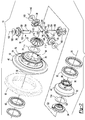
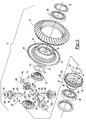
Figures 2 and3 are exploded views of the differential assembly. -
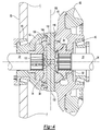
Figure 4 is a section view of the differential assembly along section line 4-4. - As required, detailed embodiments of the present invention are disclosed herein; however, it is to be understood that the disclosed embodiments are merely exemplary of the invention that may be embodied in various and alternative forms. The figures are not necessarily to scale; some features may be exaggerated or minimized to show details of particular components. Therefore, specific structural and functional details disclosed herein are not to be interpreted as limiting, but merely as a representative basis for teaching one skilled in the art to variously employ the present invention.
- Referring to
Figure 1 , an exemplarydifferential assembly 10 is shown. Thedifferential assembly 10 may be configured for use with a vehicle, such as a motor vehicle like a truck, bus, farm equipment, military transport or weaponry vehicle, or cargo loading equipment for land, air, or marine vessels. - The
differential assembly 10 may be provided with a vehicle drivetrain component, such as an axle assembly or transfer case, or wheel hub assembly. For example, thedifferential assembly 10 may be configured as an interaxle differential unit that may be provided with an axle assembly to compensate for speed differences between different axle assemblies that may be connected in series. Thedifferential assembly 10 may also be provided with a wheel hub assembly that may rotatably support a vehicle wheel to provide gear reduction or gear ratio modification between a wheel axle and a traction wheel. Thedifferential assembly 10 is described below primarily in the context of an axle assembly 12 and more specifically as adifferential assembly 10 that may transmit torque to two wheel axles and their associated traction wheel assemblies and may permit the wheel axles and traction wheel assemblies to rotate at different velocities. As such, thedifferential assembly 10 may facilitate the transfer of torque between components and/or allow components to rotate at different velocities. - Referring to
Figure 4 , the axle assembly 12 may include ahousing 20, afirst shaft 22, and asecond shaft 24. - The
housing 20 may receive thedifferential assembly 10 and various components of the axle assembly 12. In addition, thehousing 20 may facilitate mounting of the axle assembly 12 to the vehicle. InFigure 4 , only a portion of thehousing 20 is shown to more clearly illustrate thedifferential assembly 10. - The
first shaft 22 and thesecond shaft 24 may be at least partially disposed in thehousing 20. In addition, thefirst shaft 22 and thesecond shaft 24 may be spaced apart from each other and may extend in opposite directions from thedifferential assembly 10. Thefirst shaft 22 and thesecond shaft 24 may be configured to rotate about anaxis 26. For instance, thefirst shaft 22 and thesecond shaft 24 may rotate independently or at different speeds about theaxis 26 due to operation of thedifferential assembly 10. In at least one embodiment, thefirst shaft 22 and thesecond shaft 24 may be wheel axles or may be operatively connected to corresponding wheel axles that may be connected to corresponding wheel assemblies. As such, thefirst shaft 22 and/or thesecond shaft 24 may be rotated about theaxis 26 by thedifferential assembly 10 to provide torque to a corresponding wheel assembly. In an interaxle differential unit configuration, thefirst shaft 22 may be an input shaft that may receive an input torque and thesecond shaft 24 may be an output shaft that may provide torque to another axle assembly. In a wheel hub assembly configuration, thefirst shaft 22 may be a wheel axle or may receive an input torque from a wheel axle and thesecond shaft 24 may provide torque to a wheel assembly. - Referring to
Figures 1-3 , an example of adifferential assembly 10 is shown in more detail. In at least one embodiment, thedifferential assembly 10 may include acase 30, afirst gear 32, asecond gear 34, aspider 36, and at least onepinion gear 38. - The
case 30 may be configured to receive components of thedifferential assembly 10. In addition, thecase 30 may be configured to rotate about theaxis 26. In at least one embodiment, thecase 30 may include afirst case portion 40 and asecond case portion 42 that may cooperate to at least partially define a cavity. The cavity may at least partially receive thefirst gear 32,second gear 34,spider 36, and pinion gear(s) 38. - Referring to
Figures 2 and3 , an example of afirst case portion 40 is shown. Thefirst case portion 40 may include afirst bearing portion 50, aflange portion 52, a first mountingportion 54, afirst cavity 56, and afirst hole 58. - The
first bearing portion 50 may extend around theaxis 26 and may extend around and may at least partially define thefirst hole 58. As is best shown inFigure 4 , thefirst bearing portion 50 may be disposed proximate and may engage abearing 60 that may rotatably support thefirst case portion 40. Thebearing 60 may be a roller bearing assembly that may include a plurality of rolling elements, such as balls or rollers, which may be disposed between an inner race and an outer race. Thebearing 60 may be mounted on another component, such as thehousing 20. - The
flange portion 52 may be disposed between thefirst bearing portion 50 and the first mountingportion 54. Theflange portion 52 may extend away from theaxis 26 and may extend further away from theaxis 26 than thefirst bearing portion 50 and the first mountingportion 54. Aring gear 62 may be fixedly mounted to theflange portion 52 in some differential configurations, such as when thedifferential assembly 10 is provided in an axle assembly 12 and thefirst shaft 22 andsecond shaft 24 are wheel axles or transmit torque to wheel axles and traction wheel assemblies. Thering gear 62 may engage a pinion and receive torque from a pinion that may receive torque from a drivetrain component, such as an internal combustion engine, transmission, or transfer case. Torque provided to the pinion may be transmitted to thering gear 62 and then to corresponding wheel end assemblies and traction wheels via thefirst shaft 22 and thesecond shaft 24. Alternatively, the ring gear may be omitted in various configurations, such as when the differential assembly is configured as an interaxle differential unit. - The first mounting
portion 54 may extend from theflange portion 52 toward thesecond case portion 42. As is best shown inFigure 2 , the first mountingportion 54 may extend around and may at least partially define thefirst cavity 56. In at least one embodiment, the first mountingportion 54 may have anouter surface 70, a set of spider shaft holes 72, aninner wall 74, anouter wall 76, and arecess 78. - The
outer surface 70 may be an exterior of the first mountingportion 54. The outer surface may extend around theaxis 26 and thefirst cavity 56 and may face away from thefirst cavity 56. - The set of spider shaft holes 72 may be provided in the first mounting
portion 54. Aspider shaft hole 72 may receive a spider shaft of thespider 36 as will be discussed in more detail below. In the embodiment shown inFigure 2 , four spider shaft holes 72 are shown; however, it is contemplated that a greater or lesser number of spider shaft holes 72 may be provided. The spider shaft holes 72 may be spaced apart from each other and may be arranged around theaxis 26. For example, spider shaft holes 72 may be disposed along axes that may be disposed substantially perpendicular to theaxis 26. The spider shaft holes 72 may be through holes that may be completely defined in thefirst case portion 40. For example, spider shaft holes 72 may extend from thefirst cavity 56 to theouter surface 70. - The
inner wall 74 may extend from an end of the first mountingportion 54 toward thesecond case portion 42. Theinner wall 74 may at least partially define thefirst cavity 56. As such, theinner wall 74 may be disposed between thefirst cavity 56 and therecess 78. For example, theinner wall 74 may extend from thefirst cavity 56 to therecess 78. Theinner wall 74 may be configured as a ring that may extend continuously around theaxis 26 in one or more embodiments. In addition, theinner wall 74 may extend further from theflange portion 52 than theouter wall 76 in an axial direction or a direction parallel to theaxis 26. - The
outer wall 76 may also extend from an end of the first mountingportion 54 toward thesecond case portion 42. Theouter wall 76 may at least partially define theouter surface 70 in one or more embodiments. Theouter wall 76 may cooperate with theinner wall 74 to at least partially define therecess 78. As such, theouter wall 76 may be disposed between theouter surface 70 and therecess 78. For example, theouter wall 76 may extend from theouter surface 70 to therecess 78. Theouter wall 76 may be configured as a ring that may extend continuously around theaxis 26. - The
recess 78 may be disposed between thefirst cavity 56 and theouter surface 70. For instance, therecess 78 may be disposed between theinner wall 74 and theouter wall 76 and may be spaced apart from or separated from thefirst cavity 56 and theouter surface 70. Therecess 78 may extend to one or more spider shaft holes 72. As such, therecess 78 may intersect and may not be separated from aspider shaft hole 72. In the embodiment shown inFigure 2 , therecess 78 is configured as a ring that may be radially disposed about theaxis 26 and that may extend continuously around theaxis 26 and may extend from an end of the first mountingportion 54 to the spider shaft holes 72. Alternatively, therecess 78 may not extend continuously around theaxis 26. For example, a plurality ofrecesses 78 may be provided that may each extend from a correspondingspider shaft hole 72 to an end of the first mountingportion 54 such that one or more recesses may be spaced apart from each other. - The
first cavity 56 may be disposed in thefirst case portion 40. Thefirst cavity 56 may receive thefirst gear 32,spider 36, and at least a portion of apinion gear 38. In addition, thefirst cavity 56 may extend from an end of the first mountingportion 54 to thefirst hole 58. - The
first hole 58 may be disposed along theaxis 26. Thefirst hole 58 may be configured to receive thefirst shaft 22 and/or thefirst gear 32. For example, thefirst hole 58 may be provided with a stepped configuration that may help position and inhibit axial movement of thefirst gear 32 away from thesecond gear 34. Thefirst hole 58 may also receive abearing 60 that may rotatably support thecase 30 as is best shown inFigure 4 . - Referring to
Figures 2 and3 , thesecond case portion 42 may be mounted to and may not rotate with respect to thefirst case portion 40. For instance, thesecond case portion 42 may be welded to thefirst case portion 40 with a weld that may extend from theouter surface 70 toward theaxis 26 and may extend continuously around theaxis 26. Alternatively, thefirst case portion 40 and thesecond case portion 42 may be assembled using one or more fasteners, such as bolts. In at least one embodiment, thesecond case portion 42 may include asecond bearing portion 80, a second mountingportion 82, asecond cavity 84, and asecond hole 86. - The
second bearing portion 80 may extend around theaxis 26 and may extend around thesecond hole 86. As is best shown inFigure 4 , abearing 60 that rotatably supports thesecond case portion 42 may be disposed on thesecond bearing portion 80. Thebearing 60 may be mounted on another component, such as thehousing 20.Gear teeth 90 may be provided with thesecond bearing portion 80 to facilitate locking of thedifferential assembly 10. For instance, a clutch collar may selectively engage thegear teeth 90 to lock thedifferential assembly 10 and inhibit thesecond shaft 24 from rotating with respect to thecase 30 and thefirst shaft 22 in a manner known by those skilled in the art. - The second mounting
portion 82 may extend outwardly from thesecond bearing portion 80 toward thefirst case portion 40. As is best shown inFigure 3 , the second mountingportion 82 may extend around and may at least partially define thesecond cavity 84. In at least one embodiment, the second mountingportion 82 may have aprotrusion 100. - The
protrusion 100 may be disposed between thesecond cavity 84 and anouter surface 102 of thesecond case portion 42. Theprotrusion 100 may be configured as a ring that may extend continuously around theaxis 26 and theinner wall 74 of thefirst case portion 40. Theprotrusion 100 may also be radially disposed about theaxis 26. In addition theprotrusion 100 may extend from an end of the second mountingportion 82 through therecess 78 and into one or more spider shaft holes 72 when thecase 30 is assembled. Alternately, theprotrusion 100 may not extend continuously around theaxis 26. For example a plurality ofprotrusions 100 may be provided that may be spaced apart from each other and that may extend through arecess 78 and into a correspondingspider shaft hole 72. As is best shown inFigure 4 , agap 104 may be provided between anexterior surface 106 of theprotrusion 100 and theouter wall 76. Thegap 104 may provide clearance that may allow a weld that joins thefirst case portion 40 to thesecond case portion 42 to fully penetrate to thegap 104 but not penetrate theprotrusion 100. Theexterior surface 106 may be an outside circumference of theprotrusion 100. - Referring again to
Figures 2 and3 , thesecond cavity 84 may be disposed in thesecond case portion 42. Thesecond cavity 84 may receive thesecond gear 34 and may receive a portion of apinion gear 38. For instance, theinner wall 74 may extend into and may be received in thesecond cavity 84. Thesecond cavity 84 may extend from an end of the second mountingportion 82 to thesecond hole 86. - The
second hole 86, which is best shown inFigure 3 , may be disposed along theaxis 26. Thesecond hole 86 may be configured to receive thesecond shaft 24 and/or thesecond gear 34. For example, thesecond hole 86 may be provided with a stepped configuration that may help position and inhibit axial movement of thesecond gear 34 away from thefirst gear 32. - The
first gear 32 may be disposed in thefirst case portion 40. For example, thefirst gear 32 may be at least partially disposed in thefirst hole 58 and may be configured to rotate about theaxis 26. In at least one embodiment, thefirst gear 32 may include afirst gear hole 110 and agear portion 112. - The
first gear hole 110 may be disposed along theaxis 26. Thefirst gear hole 110 may be configured to receive thefirst shaft 22. Thefirst gear 32 may rotate with thefirst shaft 22. For example, thefirst gear hole 110 may have a spline that may mate with a corresponding spline on thefirst shaft 22 such that thefirst gear 32 may not rotate with respect to thefirst shaft 22. - The
gear portion 112 may face toward and may be spaced apart from thespider 36. Thegear portion 112 may have a set of teeth that may be arranged around theaxis 26 and that may mate with teeth on one or more pinion gears 38. Athrust washer 114 or bearing may be disposed between thegear portion 112 and thefirst case portion 40. - The
second gear 34 may be disposed in thesecond case portion 42. For example, thesecond gear 34 may be at least partially disposed in thesecond hole 86 and may be configured to rotate about theaxis 26. Thesecond gear 34 may be spaced apart from thefirst gear 32 and may have a similar or identical configuration as thefirst gear 32. In at least one embodiment, thesecond gear 34 may include asecond gear hole 120 and agear portion 122. - The
second gear hole 120 may be disposed along theaxis 26. Thesecond gear hole 120 may be configured to receive thesecond shaft 24. In at least one embodiment, thesecond gear 34 may rotate with thefirst shaft 22. For example, thesecond gear hole 120 may have a spline that may mate with a corresponding spline on thesecond shaft 24 such that thesecond gear 34 may not rotate with respect to thesecond shaft 24. - The
gear portion 122 may face toward and may be spaced apart from thespider 36. Thegear portion 122 may have a set of teeth that may be arranged around theaxis 26 and that may mate with teeth on one or more pinion gears 38. Athrust washer 114 or bearing may be disposed between thegear portion 122 and thesecond case portion 42. - The
spider 36 may rotate about theaxis 26 with thecase 30. In at least one embodiment, thespider 36 may include aprimary spider shaft 130 and at least onesecondary spider shaft 132. - The
primary spider shaft 130 may be mounted to thefirst case portion 40. For example, theprimary spider shaft 130 may have opposing ends that may be received in corresponding spider shaft holes 72 of thefirst case portion 40. As such, theprimary spider shaft 130 may extend across thefirst cavity 56 and may extend through theaxis 26. Theprimary spider shaft 130 may be disposed along a primaryspider shaft axis 140. The primaryspider shaft axis 140 may intersect and may be disposed substantially perpendicular to theaxis 26. Theprimary spider shaft 130 may have a generally cylindrical configuration and may include anotch 142, alubricant groove 144, and a retaininggroove 146. - One or
more notches 142 may be disposed proximate the center of theprimary spider shaft 130. In the embodiment shown inFigures 2 and3 , twonotches 142 are provided that are disposed opposite each other and extend inwardly toward theaxis 26. Anotch 142 may receive and facilitate positioning of asecondary spider shaft 132 with respect to theprimary spider shaft 130. - One or
more lubricant grooves 144 may be disposed between theaxis 26 and an end of theprimary spider shaft 130. For instance, alubricant groove 144 may be disposed between theaxis 26 and a retaininggroove 146. In the embodiment shown inFigures 2 and3 , a pair oflubricant grooves 144 is disposed proximate opposite ends of theprimary spider shaft 130. Each pair oflubricant grooves 144 may have two grooves that may be disposed opposite each other and extend toward the primaryspider shaft axis 140. Thelubricant groove 144 may be disposed adjacent to apinion gear 38 and may allow lubricant, such as oil, to flow between the hole of thepinion gear 38 and the outside of theprimary spider shaft 130 to help reduce friction between thepinion gear 38 and theprimary spider shaft 130. Thelubricant grooves 144 may have a greater axial length or length in a direction that extends along the primaryspider shaft axis 140 than the retaininggrooves 146. - One or more retaining
grooves 146 may be disposed between theaxis 26 and an end of theprimary spider shaft 130. For instance, a retaininggroove 146 may be disposed between thelubricant groove 144 and an end of theprimary spider shaft 130. In addition, the retaininggroove 146 may be spaced apart or separated from thelubricant groove 144. In the embodiment shown inFigures 2 and3 , two retaininggrooves 146 are provided that are disposed directly opposite each other and extend toward the primaryspider shaft axis 140. At least one retaininggroove 146 may face toward thesecond case portion 42 and may receive and may engage theprotrusion 100 of thesecond case portion 42. As such, theprotrusion 100 may help inhibit movement of theprimary spider shaft 130 along the primaryspider shaft axis 140 and rotation of theprimary spider shaft 130 about the primaryspider shaft axis 140. - One or more
secondary spider shafts 132 may be mounted to thefirst case portion 40. Thesecondary spider shaft 132 may extend between aspider shaft hole 72 and theprimary spider shaft 130. For example, thesecondary spider shaft 132 may have a first end that may be received in thenotch 142 of theprimary spider shaft 130 and a second end that may be disposed opposite the first end and may be received in a correspondingspider shaft hole 72. Thesecondary spider shaft 132 may be disposed along a secondaryspider shaft axis 150. The secondaryspider shaft axis 150 may intersect and may be disposed substantially perpendicular to theaxis 26 and the primaryspider shaft axis 140. In addition, the primaryspider shaft axis 140 and secondaryspider shaft axis 150 may be substantially coplanar or disposed in a common plane. In the embodiment shown inFigures 2 and3 , twosecondary spider shafts 132 are provided that are disposed on opposite sides of theprimary spider shaft 130 and are coaxially disposed along the secondaryspider shaft axis 150. Thesecondary spider shafts 132 may have common or substantially identical configurations that may include atapered end 152, alubricant groove 154, and a retaininggroove 156. - The
tapered end 152 may be disposed proximate theprimary spider shaft 130. For example thetapered end 152 may be received in anotch 142 of theprimary spider shaft 130. Thesecondary spider shaft 132 and itstapered end 152 may not be fixedly attached to theprimary spider shaft 130 in one or more embodiments. - One or
more lubricant grooves 154 may be disposed between theaxis 26 and an end of thesecondary spider shaft 132. For instance, alubricant groove 154 may be disposed between theaxis 26 and a retaininggroove 156 of thesecondary spider shaft 132. In the embodiment shown inFigures 2 and3 , twolubricant grooves 154 are provided that are disposed opposite each other and extend toward the secondaryspider shaft axis 150. Thelubricant groove 154 may be disposed adjacent to apinion gear 38 and may allow lubricant, such as oil, to flow between the hole of thepinion gear 38 and the outside of thesecondary spider shaft 132 to help reduce friction between thepinion gear 38 and thesecondary spider shaft 132. Thelubricant grooves 154 may have a greater axial length or length in a direction that extends along the secondaryspider shaft axis 150 than the retaininggrooves 156. - One or more retaining
grooves 156 may be disposed between theaxis 26 and an end of thesecondary spider shaft 132. For instance, a retaininggroove 156 may be disposed between thelubricant groove 154 and an end of thesecondary spider shaft 132. In addition, the retaininggroove 156 may be spaced apart from thelubricant groove 154. In the embodiment shown inFigures 2 and3 , two retaininggrooves 156 are provided that are disposed directly opposite each other and extend toward the secondaryspider shaft axis 150. At least one retaininggroove 156 may face toward thesecond case portion 42 and may receive and may engage theprotrusion 100 of thesecond case portion 42. As such, theprotrusion 100 may help inhibit movement of thesecondary spider shaft 132 along the secondaryspider shaft axis 150 and rotation of thesecondary spider shaft 132 about the secondaryspider shaft axis 150. - A
pinion gear 38 may be rotatably disposed on theprimary spider shaft 130 and thesecondary spider shafts 132. For instance, two pinion gears 38 may be disposed on theprimary spider shaft 130 proximatecorresponding lubricant grooves 144 while asingle pinion gear 38 may be disposed on eachsecondary spider shaft 132 proximate acorresponding lubricant groove 154. Eachpinion gear 38 may be disposed in the cavity of thecase 30 and may be retained on a corresponding spider shaft with one ormore fasteners 160, such as a washer and/or a thrust bearing. Thefastener 160 may engage theinner wall 74 of thefirst case portion 40. The pinion gears 38 on theprimary spider shaft 130 may rotate about the primaryspider shaft axis 140. Thepinion gear 38 on thesecondary spider shaft 132 may rotate about the secondaryspider shaft axis 150. Eachpinion gear 38 may include a set of teeth that mate with teeth on thefirst gear 32 and teeth on thesecond gear 34. - The differential assembly described above may allow a multi-piece spider having one or more spider shafts to be retained in a case of a differential prior to joining the first and second case portions together, thereby facilitating assembly. In addition, the differential assembly described above may allow the positioning of spider shafts to be readily inspected and checked prior to welding the first and second case portions. The differential assembly described above may also allow one or more spider shafts to be retained without the use of additional fasteners or separate fasteners, such as a screw or roll pin, thereby reducing the number of parts, assembly time, and associated costs.
- While exemplary embodiments are described above, it is not intended that these embodiments describe all possible forms of the invention. Rather, the words used in the specification are words of description rather than limitation, and it is understood that various changes may be made without departing from the spirit and scope of the invention. Additionally, the features of various implementing embodiments may be combined to form further embodiments of the invention.
Claims (15)
- A differential assembly comprising:a case that includes:a first case portion that has a first cavity, an outer surface that is disposed around the first cavity, a spider shaft hole that extends from the outer surface to the first cavity, and a recess that is disposed between the outer surface and the first cavity and that extends from the spider shaft hole; anda second case portion that is disposed on the first case portion, wherein the second case portion has a protrusion that extends through the recess into the spider shaft hole; anda spider that includes:a primary spider shaft that is mounted to the first case portion; anda secondary spider shaft that is received in the spider shaft hole and that extends between the spider shaft hole and the primary spider shaft, wherein the secondary spider shaft has a retaining groove that receives the protrusion to retain the secondary spider shaft in the spider shaft hole.
- The differential assembly of claim 1 wherein the case is configured to rotate about an axis and the recess extends continuously around the axis.
- The differential assembly of claim 2 wherein the protrusion extends continuously around the axis and preferably engages the secondary spider shaft.
- The differential assembly of claim 1 wherein the recess is spaced apart from the outer surface and the first cavity.
- The differential assembly of claim 4 wherein the first case portion further comprises an inner wall and an outer wall that cooperate to at least partially define the recess, wherein the inner wall extends from the first cavity to the recess and the outer wall extends from the outer surface to the recess.
- The differential assembly of claim 5 wherein the second case portion has a second cavity that extends from the first cavity, wherein the inner wall is received in the second cavity.
- The differential assembly of claim 6 wherein the case is configured to rotate about an axis and the inner wall and the outer wall extend continuously around the axis and preferably the protrusion extends continuously around the inner wall of the first case portion.
- The differential assembly of claim 1 wherein the spider shaft hole is a through hole that is completely defined in the first case portion.
- The differential assembly of claim 1 further comprising a pinion that is rotatably disposed on the secondary spider shaft, wherein the secondary spider shaft has a lubricant groove that is disposed between the pinion and the secondary spider shaft and is separated from the retaining groove.
- The differential assembly of claim 1 wherein the primary spider shaft has a notch that receives a tapered end of the secondary spider shaft such that the secondary spider shaft is not fixedly attached to the primary spider shaft.
- The differential assembly of claim 1 wherein the first case portion includes a set of spider shaft holes that are spaced apart from each other and extend from the outer surface to the first cavity, and the recess extends from each member of the set of spider shaft holes, the protrusion extends into each member of the set of spider shaft holes, the primary spider shaft is received in first and second members of the set of spider shaft holes, and the secondary spider shaft is received in a third member of the set of spider shaft holes and that extends from the third member to the primary spider shaft.
- The differential assembly of claim 11 wherein the spider further comprises a second secondary spider shaft that is received in a fourth member of the set of spider shaft holes and that extends from the fourth member to the primary spider shaft, preferably wherein the second secondary spider shaft has a retaining groove that receives and engages the protrusion to retain the second secondary spider shaft in the spider shaft hole.
- The differential assembly of claim 1 wherein the primary spider shaft has a pair of retaining grooves disposed proximate opposite ends of the primary spider shaft, wherein the protrusion is received in the pair of retaining grooves.
- The differential assembly of claim 12 wherein the primary spider shaft is disposed along a primary spider shaft axis and the secondary spider shaft and the second secondary spider shaft are disposed along a secondary spider shaft axis, preferably wherein the primary spider shaft and the primary spider shaft axis both intersect an axis about which the case is rotatable.
- The differential assembly of claim 1 further comprising a first gear disposed in the first cavity, a second gear disposed in a second cavity of the second case portion, and at least one pinion gear that engages the first gear and the second gear, wherein at least one pinion gear is rotatably disposed on the primary spider shaft and at least one pinion gear is disposed on the secondary spider shaft.
Applications Claiming Priority (1)
| Application Number | Priority Date | Filing Date | Title |
|---|---|---|---|
| US14/996,663 US9797496B2 (en) | 2016-01-15 | 2016-01-15 | Differential assembly with spider shaft retention |
Publications (2)
| Publication Number | Publication Date |
|---|---|
| EP3193044A1 true EP3193044A1 (en) | 2017-07-19 |
| EP3193044B1 EP3193044B1 (en) | 2019-06-26 |
Family
ID=57211309
Family Applications (1)
| Application Number | Title | Priority Date | Filing Date |
|---|---|---|---|
| EP16195368.2A Active EP3193044B1 (en) | 2016-01-15 | 2016-10-24 | Differential assembly with spider shaft retention |
Country Status (4)
| Country | Link |
|---|---|
| US (1) | US9797496B2 (en) |
| EP (1) | EP3193044B1 (en) |
| CN (1) | CN106979307B (en) |
| BR (1) | BR102016025424A2 (en) |
Families Citing this family (9)
| Publication number | Priority date | Publication date | Assignee | Title |
|---|---|---|---|---|
| USD869530S1 (en) * | 2016-04-01 | 2019-12-10 | Apex Dynamics, Inc | Gear |
| USD879171S1 (en) * | 2016-04-01 | 2020-03-24 | Apex Dynamics, Inc | Gear |
| US20170284474A1 (en) * | 2016-04-01 | 2017-10-05 | Apex Dynamics, Inc. | Coupler for a power take-out axle of a gearbox |
| US11231099B2 (en) * | 2016-11-09 | 2022-01-25 | Arvinmeritor Technology, Llc | Axle assembly and differential assembly with spider shaft retention |
| US10156289B2 (en) * | 2017-03-07 | 2018-12-18 | Meritor do Brasil Sistemas Automotivos Ltda. | Axle assembly having multiple clutch collars |
| US20190113082A1 (en) | 2017-09-08 | 2019-04-18 | Kanzaki Kokyukoki Mfg. Co., Ltd. | Differential gear |
| EP4015872B1 (en) * | 2020-12-18 | 2025-12-24 | Ningbo Geely Automobile Research & Development Co. Ltd. | A differential gear assembly, a vehicle comprising a differential gear assembly, and a method for assembling parts of a differential gear assembly |
| US11448300B1 (en) * | 2021-06-15 | 2022-09-20 | Schaeffler Technologies AG & Co. KG | Sealed planetary differential |
| DE102024114910B4 (en) * | 2024-05-28 | 2025-12-18 | Schaeffler Technologies AG & Co. KG | Multi-piece differential gear bolt and differential gear with a multi-piece differential gear bolt |
Citations (3)
| Publication number | Priority date | Publication date | Assignee | Title |
|---|---|---|---|---|
| US20090013533A1 (en) * | 2007-07-10 | 2009-01-15 | Isken Ii Dennis W | Differential mechanism assembly |
| DE102012014950A1 (en) * | 2011-07-30 | 2013-01-31 | Daimler Ag | Housing for differential gear of motor vehicle e.g. passenger car, has division planes that are arranged in housing portions in which openings are formed for receiving portions of bearing pins, and are welded at housing portions |
| US20150059180A1 (en) | 2013-08-28 | 2015-03-05 | Arvinmeritor Technology, Llc | Method of Making a Bevel Gear System |
Family Cites Families (18)
| Publication number | Priority date | Publication date | Assignee | Title |
|---|---|---|---|---|
| US3915267A (en) * | 1973-08-02 | 1975-10-28 | Dana Corp | Differential and braking assembly |
| US4860614A (en) * | 1988-07-26 | 1989-08-29 | Deere & Company | Transmission differential |
| US5273498A (en) * | 1992-12-07 | 1993-12-28 | New Venture Gear, Inc. | Differential mechanism |
| JP2976204B1 (en) * | 1998-06-09 | 1999-11-10 | 本田技研工業株式会社 | Lubrication structure in differential equipment |
| US6045479A (en) | 1998-08-10 | 2000-04-04 | Ford Global Technologies, Inc. | Differential mechanism for an automotive vehicle having a cold formed housing assembly |
| US6802793B2 (en) * | 2003-02-17 | 2004-10-12 | American Axle & Manufacturing, Inc. | Cross pin retention system for differentials |
| US7291083B2 (en) | 2004-08-04 | 2007-11-06 | Arvinmeritor Technology, Llc | Inter-axle differential assembly |
| US7367914B2 (en) * | 2005-02-25 | 2008-05-06 | Ronjo Company | Differential housing support member |
| US7695392B2 (en) | 2007-07-10 | 2010-04-13 | Ford Global Technologies, Llc | Differential mechanism assembly |
| US7819040B2 (en) * | 2007-11-28 | 2010-10-26 | Transform Automotive Llc | Method for making vehicle axle differential casing and resultant product |
| US20100151983A1 (en) * | 2008-12-11 | 2010-06-17 | Ziech James F | Spider-less vehicle differential |
| CN202220842U (en) * | 2011-08-15 | 2012-05-16 | 方盛车桥(柳州)有限公司 | Reinforced main speed reducer capable of being equipped with retarder on reducer casing |
| US8651994B2 (en) | 2011-09-30 | 2014-02-18 | Arvinmeritor Technology, Llc | Drive axle assembly and disengagement system |
| CN102537272B (en) * | 2012-03-06 | 2014-07-23 | 中国人民解放军装甲兵工程学院 | Differential and transfer case for 4 wheel driven amphibious vehicle |
| CN202579895U (en) * | 2012-05-14 | 2012-12-05 | 重庆市望达机械制造有限公司 | Minicar rear axle final drive assembly |
| US8535191B1 (en) | 2012-07-17 | 2013-09-17 | Gkn Driveline North America, Inc. | Aluminum flange with anti-rotation slots |
| US9109635B2 (en) | 2013-02-07 | 2015-08-18 | Arvinmeritor Technology, Llc | Axle assembly having a moveable clutch collar |
| BR112014032706A2 (en) * | 2013-10-23 | 2017-06-27 | Eaton Corp | selectively locking differential and vehicle transmission |
-
2016
- 2016-01-15 US US14/996,663 patent/US9797496B2/en active Active
- 2016-09-09 CN CN201610812252.3A patent/CN106979307B/en not_active Expired - Fee Related
- 2016-10-24 EP EP16195368.2A patent/EP3193044B1/en active Active
- 2016-10-31 BR BR102016025424-8A patent/BR102016025424A2/en not_active IP Right Cessation
Patent Citations (3)
| Publication number | Priority date | Publication date | Assignee | Title |
|---|---|---|---|---|
| US20090013533A1 (en) * | 2007-07-10 | 2009-01-15 | Isken Ii Dennis W | Differential mechanism assembly |
| DE102012014950A1 (en) * | 2011-07-30 | 2013-01-31 | Daimler Ag | Housing for differential gear of motor vehicle e.g. passenger car, has division planes that are arranged in housing portions in which openings are formed for receiving portions of bearing pins, and are welded at housing portions |
| US20150059180A1 (en) | 2013-08-28 | 2015-03-05 | Arvinmeritor Technology, Llc | Method of Making a Bevel Gear System |
Also Published As
| Publication number | Publication date |
|---|---|
| CN106979307A (en) | 2017-07-25 |
| EP3193044B1 (en) | 2019-06-26 |
| US20170204956A1 (en) | 2017-07-20 |
| BR102016025424A2 (en) | 2018-02-14 |
| CN106979307B (en) | 2019-03-19 |
| US9797496B2 (en) | 2017-10-24 |
Similar Documents
| Publication | Publication Date | Title |
|---|---|---|
| EP3193044B1 (en) | Differential assembly with spider shaft retention | |
| US10208846B2 (en) | Axle assembly having a drive pinion support bearing and a method of assembly | |
| US9719563B2 (en) | Axle assembly having a tapered spline arrangement | |
| EP3766716B1 (en) | Axle assembly having a drive pinion assembly | |
| US9410605B2 (en) | Differential assembly having a link shaft | |
| US10001201B2 (en) | Axle assembly with interaxle differential support | |
| CN112644273B (en) | Axle assembly with differential assembly | |
| EP3144561B1 (en) | Bogie axle assembly | |
| US9506549B2 (en) | Differential assembly | |
| EP4112353A1 (en) | Axle assembly having an interaxle differential unit | |
| EP3144172A1 (en) | Bogie axle system | |
| EP4108494B1 (en) | Axle assembly having an interaxle differential unit | |
| EP4311703A1 (en) | Axle assembly having an interaxle differential unit | |
| US11231099B2 (en) | Axle assembly and differential assembly with spider shaft retention | |
| US7690449B2 (en) | Output yoke shaft and assembly | |
| US10011147B2 (en) | Axle assembly having an adjuster ring | |
| US20090280946A1 (en) | Vehicular differential gear apparatus | |
| US10941846B2 (en) | Differential assembly having an overhanging ring gear | |
| US20170363196A1 (en) | Driving force distributing apparatus |
Legal Events
| Date | Code | Title | Description |
|---|---|---|---|
| PUAI | Public reference made under article 153(3) epc to a published international application that has entered the european phase |
Free format text: ORIGINAL CODE: 0009012 |
|
| STAA | Information on the status of an ep patent application or granted ep patent |
Free format text: STATUS: THE APPLICATION HAS BEEN PUBLISHED |
|
| AK | Designated contracting states |
Kind code of ref document: A1 Designated state(s): AL AT BE BG CH CY CZ DE DK EE ES FI FR GB GR HR HU IE IS IT LI LT LU LV MC MK MT NL NO PL PT RO RS SE SI SK SM TR |
|
| AX | Request for extension of the european patent |
Extension state: BA ME |
|
| STAA | Information on the status of an ep patent application or granted ep patent |
Free format text: STATUS: REQUEST FOR EXAMINATION WAS MADE |
|
| 17P | Request for examination filed |
Effective date: 20171222 |
|
| RBV | Designated contracting states (corrected) |
Designated state(s): AL AT BE BG CH CY CZ DE DK EE ES FI FR GB GR HR HU IE IS IT LI LT LU LV MC MK MT NL NO PL PT RO RS SE SI SK SM TR |
|
| RIC1 | Information provided on ipc code assigned before grant |
Ipc: F16H 48/08 20060101ALI20181210BHEP Ipc: F16H 48/40 20120101AFI20181210BHEP |
|
| GRAP | Despatch of communication of intention to grant a patent |
Free format text: ORIGINAL CODE: EPIDOSNIGR1 |
|
| STAA | Information on the status of an ep patent application or granted ep patent |
Free format text: STATUS: GRANT OF PATENT IS INTENDED |
|
| INTG | Intention to grant announced |
Effective date: 20190121 |
|
| GRAS | Grant fee paid |
Free format text: ORIGINAL CODE: EPIDOSNIGR3 |
|
| GRAA | (expected) grant |
Free format text: ORIGINAL CODE: 0009210 |
|
| STAA | Information on the status of an ep patent application or granted ep patent |
Free format text: STATUS: THE PATENT HAS BEEN GRANTED |
|
| AK | Designated contracting states |
Kind code of ref document: B1 Designated state(s): AL AT BE BG CH CY CZ DE DK EE ES FI FR GB GR HR HU IE IS IT LI LT LU LV MC MK MT NL NO PL PT RO RS SE SI SK SM TR |
|
| REG | Reference to a national code |
Ref country code: GB Ref legal event code: FG4D |
|
| REG | Reference to a national code |
Ref country code: CH Ref legal event code: EP |
|
| REG | Reference to a national code |
Ref country code: AT Ref legal event code: REF Ref document number: 1148672 Country of ref document: AT Kind code of ref document: T Effective date: 20190715 |
|
| REG | Reference to a national code |
Ref country code: DE Ref legal event code: R096 Ref document number: 602016015834 Country of ref document: DE |
|
| REG | Reference to a national code |
Ref country code: IE Ref legal event code: FG4D |
|
| REG | Reference to a national code |
Ref country code: SE Ref legal event code: TRGR |
|
| REG | Reference to a national code |
Ref country code: NL Ref legal event code: MP Effective date: 20190626 |
|
| PG25 | Lapsed in a contracting state [announced via postgrant information from national office to epo] |
Ref country code: LT Free format text: LAPSE BECAUSE OF FAILURE TO SUBMIT A TRANSLATION OF THE DESCRIPTION OR TO PAY THE FEE WITHIN THE PRESCRIBED TIME-LIMIT Effective date: 20190626 Ref country code: HR Free format text: LAPSE BECAUSE OF FAILURE TO SUBMIT A TRANSLATION OF THE DESCRIPTION OR TO PAY THE FEE WITHIN THE PRESCRIBED TIME-LIMIT Effective date: 20190626 Ref country code: FI Free format text: LAPSE BECAUSE OF FAILURE TO SUBMIT A TRANSLATION OF THE DESCRIPTION OR TO PAY THE FEE WITHIN THE PRESCRIBED TIME-LIMIT Effective date: 20190626 Ref country code: AL Free format text: LAPSE BECAUSE OF FAILURE TO SUBMIT A TRANSLATION OF THE DESCRIPTION OR TO PAY THE FEE WITHIN THE PRESCRIBED TIME-LIMIT Effective date: 20190626 Ref country code: NO Free format text: LAPSE BECAUSE OF FAILURE TO SUBMIT A TRANSLATION OF THE DESCRIPTION OR TO PAY THE FEE WITHIN THE PRESCRIBED TIME-LIMIT Effective date: 20190926 |
|
| REG | Reference to a national code |
Ref country code: LT Ref legal event code: MG4D |
|
| PG25 | Lapsed in a contracting state [announced via postgrant information from national office to epo] |
Ref country code: LV Free format text: LAPSE BECAUSE OF FAILURE TO SUBMIT A TRANSLATION OF THE DESCRIPTION OR TO PAY THE FEE WITHIN THE PRESCRIBED TIME-LIMIT Effective date: 20190626 Ref country code: GR Free format text: LAPSE BECAUSE OF FAILURE TO SUBMIT A TRANSLATION OF THE DESCRIPTION OR TO PAY THE FEE WITHIN THE PRESCRIBED TIME-LIMIT Effective date: 20190927 Ref country code: RS Free format text: LAPSE BECAUSE OF FAILURE TO SUBMIT A TRANSLATION OF THE DESCRIPTION OR TO PAY THE FEE WITHIN THE PRESCRIBED TIME-LIMIT Effective date: 20190626 Ref country code: BG Free format text: LAPSE BECAUSE OF FAILURE TO SUBMIT A TRANSLATION OF THE DESCRIPTION OR TO PAY THE FEE WITHIN THE PRESCRIBED TIME-LIMIT Effective date: 20190926 |
|
| REG | Reference to a national code |
Ref country code: AT Ref legal event code: MK05 Ref document number: 1148672 Country of ref document: AT Kind code of ref document: T Effective date: 20190626 |
|
| PG25 | Lapsed in a contracting state [announced via postgrant information from national office to epo] |
Ref country code: PT Free format text: LAPSE BECAUSE OF FAILURE TO SUBMIT A TRANSLATION OF THE DESCRIPTION OR TO PAY THE FEE WITHIN THE PRESCRIBED TIME-LIMIT Effective date: 20191028 Ref country code: NL Free format text: LAPSE BECAUSE OF FAILURE TO SUBMIT A TRANSLATION OF THE DESCRIPTION OR TO PAY THE FEE WITHIN THE PRESCRIBED TIME-LIMIT Effective date: 20190626 Ref country code: RO Free format text: LAPSE BECAUSE OF FAILURE TO SUBMIT A TRANSLATION OF THE DESCRIPTION OR TO PAY THE FEE WITHIN THE PRESCRIBED TIME-LIMIT Effective date: 20190626 Ref country code: CZ Free format text: LAPSE BECAUSE OF FAILURE TO SUBMIT A TRANSLATION OF THE DESCRIPTION OR TO PAY THE FEE WITHIN THE PRESCRIBED TIME-LIMIT Effective date: 20190626 Ref country code: EE Free format text: LAPSE BECAUSE OF FAILURE TO SUBMIT A TRANSLATION OF THE DESCRIPTION OR TO PAY THE FEE WITHIN THE PRESCRIBED TIME-LIMIT Effective date: 20190626 Ref country code: AT Free format text: LAPSE BECAUSE OF FAILURE TO SUBMIT A TRANSLATION OF THE DESCRIPTION OR TO PAY THE FEE WITHIN THE PRESCRIBED TIME-LIMIT Effective date: 20190626 Ref country code: SK Free format text: LAPSE BECAUSE OF FAILURE TO SUBMIT A TRANSLATION OF THE DESCRIPTION OR TO PAY THE FEE WITHIN THE PRESCRIBED TIME-LIMIT Effective date: 20190626 |
|
| PG25 | Lapsed in a contracting state [announced via postgrant information from national office to epo] |
Ref country code: ES Free format text: LAPSE BECAUSE OF FAILURE TO SUBMIT A TRANSLATION OF THE DESCRIPTION OR TO PAY THE FEE WITHIN THE PRESCRIBED TIME-LIMIT Effective date: 20190626 Ref country code: IT Free format text: LAPSE BECAUSE OF FAILURE TO SUBMIT A TRANSLATION OF THE DESCRIPTION OR TO PAY THE FEE WITHIN THE PRESCRIBED TIME-LIMIT Effective date: 20190626 Ref country code: SM Free format text: LAPSE BECAUSE OF FAILURE TO SUBMIT A TRANSLATION OF THE DESCRIPTION OR TO PAY THE FEE WITHIN THE PRESCRIBED TIME-LIMIT Effective date: 20190626 Ref country code: IS Free format text: LAPSE BECAUSE OF FAILURE TO SUBMIT A TRANSLATION OF THE DESCRIPTION OR TO PAY THE FEE WITHIN THE PRESCRIBED TIME-LIMIT Effective date: 20191026 |
|
| PG25 | Lapsed in a contracting state [announced via postgrant information from national office to epo] |
Ref country code: TR Free format text: LAPSE BECAUSE OF FAILURE TO SUBMIT A TRANSLATION OF THE DESCRIPTION OR TO PAY THE FEE WITHIN THE PRESCRIBED TIME-LIMIT Effective date: 20190626 |
|
| PG25 | Lapsed in a contracting state [announced via postgrant information from national office to epo] |
Ref country code: DK Free format text: LAPSE BECAUSE OF FAILURE TO SUBMIT A TRANSLATION OF THE DESCRIPTION OR TO PAY THE FEE WITHIN THE PRESCRIBED TIME-LIMIT Effective date: 20190626 Ref country code: PL Free format text: LAPSE BECAUSE OF FAILURE TO SUBMIT A TRANSLATION OF THE DESCRIPTION OR TO PAY THE FEE WITHIN THE PRESCRIBED TIME-LIMIT Effective date: 20190626 |
|
| PG25 | Lapsed in a contracting state [announced via postgrant information from national office to epo] |
Ref country code: MC Free format text: LAPSE BECAUSE OF FAILURE TO SUBMIT A TRANSLATION OF THE DESCRIPTION OR TO PAY THE FEE WITHIN THE PRESCRIBED TIME-LIMIT Effective date: 20190626 Ref country code: IS Free format text: LAPSE BECAUSE OF FAILURE TO SUBMIT A TRANSLATION OF THE DESCRIPTION OR TO PAY THE FEE WITHIN THE PRESCRIBED TIME-LIMIT Effective date: 20200224 |
|
| REG | Reference to a national code |
Ref country code: CH Ref legal event code: PL |
|
| REG | Reference to a national code |
Ref country code: DE Ref legal event code: R097 Ref document number: 602016015834 Country of ref document: DE |
|
| PLBE | No opposition filed within time limit |
Free format text: ORIGINAL CODE: 0009261 |
|
| STAA | Information on the status of an ep patent application or granted ep patent |
Free format text: STATUS: NO OPPOSITION FILED WITHIN TIME LIMIT |
|
| PG2D | Information on lapse in contracting state deleted |
Ref country code: IS |
|
| PG25 | Lapsed in a contracting state [announced via postgrant information from national office to epo] |
Ref country code: LU Free format text: LAPSE BECAUSE OF NON-PAYMENT OF DUE FEES Effective date: 20191024 Ref country code: LI Free format text: LAPSE BECAUSE OF NON-PAYMENT OF DUE FEES Effective date: 20191031 Ref country code: CH Free format text: LAPSE BECAUSE OF NON-PAYMENT OF DUE FEES Effective date: 20191031 |
|
| 26N | No opposition filed |
Effective date: 20200603 |
|
| REG | Reference to a national code |
Ref country code: BE Ref legal event code: MM Effective date: 20191031 |
|
| PG25 | Lapsed in a contracting state [announced via postgrant information from national office to epo] |
Ref country code: BE Free format text: LAPSE BECAUSE OF NON-PAYMENT OF DUE FEES Effective date: 20191031 Ref country code: SI Free format text: LAPSE BECAUSE OF FAILURE TO SUBMIT A TRANSLATION OF THE DESCRIPTION OR TO PAY THE FEE WITHIN THE PRESCRIBED TIME-LIMIT Effective date: 20190626 |
|
| PG25 | Lapsed in a contracting state [announced via postgrant information from national office to epo] |
Ref country code: IE Free format text: LAPSE BECAUSE OF NON-PAYMENT OF DUE FEES Effective date: 20191024 |
|
| PG25 | Lapsed in a contracting state [announced via postgrant information from national office to epo] |
Ref country code: CY Free format text: LAPSE BECAUSE OF FAILURE TO SUBMIT A TRANSLATION OF THE DESCRIPTION OR TO PAY THE FEE WITHIN THE PRESCRIBED TIME-LIMIT Effective date: 20190626 |
|
| GBPC | Gb: european patent ceased through non-payment of renewal fee |
Effective date: 20201024 |
|
| PG25 | Lapsed in a contracting state [announced via postgrant information from national office to epo] |
Ref country code: MT Free format text: LAPSE BECAUSE OF FAILURE TO SUBMIT A TRANSLATION OF THE DESCRIPTION OR TO PAY THE FEE WITHIN THE PRESCRIBED TIME-LIMIT Effective date: 20190626 Ref country code: HU Free format text: LAPSE BECAUSE OF FAILURE TO SUBMIT A TRANSLATION OF THE DESCRIPTION OR TO PAY THE FEE WITHIN THE PRESCRIBED TIME-LIMIT; INVALID AB INITIO Effective date: 20161024 |
|
| PG25 | Lapsed in a contracting state [announced via postgrant information from national office to epo] |
Ref country code: GB Free format text: LAPSE BECAUSE OF NON-PAYMENT OF DUE FEES Effective date: 20201024 |
|
| PG25 | Lapsed in a contracting state [announced via postgrant information from national office to epo] |
Ref country code: MK Free format text: LAPSE BECAUSE OF FAILURE TO SUBMIT A TRANSLATION OF THE DESCRIPTION OR TO PAY THE FEE WITHIN THE PRESCRIBED TIME-LIMIT Effective date: 20190626 |
|
| P01 | Opt-out of the competence of the unified patent court (upc) registered |
Effective date: 20230531 |
|
| PGFP | Annual fee paid to national office [announced via postgrant information from national office to epo] |
Ref country code: DE Payment date: 20251029 Year of fee payment: 10 |
|
| PGFP | Annual fee paid to national office [announced via postgrant information from national office to epo] |
Ref country code: FR Payment date: 20251027 Year of fee payment: 10 |
|
| PGFP | Annual fee paid to national office [announced via postgrant information from national office to epo] |
Ref country code: SE Payment date: 20251027 Year of fee payment: 10 |