EP3193042A1 - Dual clutch transmission - Google Patents
Dual clutch transmission Download PDFInfo
- Publication number
- EP3193042A1 EP3193042A1 EP15840795.7A EP15840795A EP3193042A1 EP 3193042 A1 EP3193042 A1 EP 3193042A1 EP 15840795 A EP15840795 A EP 15840795A EP 3193042 A1 EP3193042 A1 EP 3193042A1
- Authority
- EP
- European Patent Office
- Prior art keywords
- gear
- shaft
- input
- counter
- output
- Prior art date
- Legal status (The legal status is an assumption and is not a legal conclusion. Google has not performed a legal analysis and makes no representation as to the accuracy of the status listed.)
- Granted
Links
Images



Classifications
-
- F—MECHANICAL ENGINEERING; LIGHTING; HEATING; WEAPONS; BLASTING
- F16—ENGINEERING ELEMENTS AND UNITS; GENERAL MEASURES FOR PRODUCING AND MAINTAINING EFFECTIVE FUNCTIONING OF MACHINES OR INSTALLATIONS; THERMAL INSULATION IN GENERAL
- F16H—GEARING
- F16H37/00—Combinations of mechanical gearings, not provided for in groups F16H1/00 - F16H35/00
- F16H37/02—Combinations of mechanical gearings, not provided for in groups F16H1/00 - F16H35/00 comprising essentially only toothed or friction gearings
- F16H37/06—Combinations of mechanical gearings, not provided for in groups F16H1/00 - F16H35/00 comprising essentially only toothed or friction gearings with a plurality of driving or driven shafts; with arrangements for dividing torque between two or more intermediate shafts
- F16H37/065—Combinations of mechanical gearings, not provided for in groups F16H1/00 - F16H35/00 comprising essentially only toothed or friction gearings with a plurality of driving or driven shafts; with arrangements for dividing torque between two or more intermediate shafts with a plurality of driving or driven shafts
-
- F—MECHANICAL ENGINEERING; LIGHTING; HEATING; WEAPONS; BLASTING
- F16—ENGINEERING ELEMENTS AND UNITS; GENERAL MEASURES FOR PRODUCING AND MAINTAINING EFFECTIVE FUNCTIONING OF MACHINES OR INSTALLATIONS; THERMAL INSULATION IN GENERAL
- F16H—GEARING
- F16H3/00—Toothed gearings for conveying rotary motion with variable gear ratio or for reversing rotary motion
- F16H3/006—Toothed gearings for conveying rotary motion with variable gear ratio or for reversing rotary motion power being selectively transmitted by parallel flow paths, e.g. dual clutch transmissions
-
- F—MECHANICAL ENGINEERING; LIGHTING; HEATING; WEAPONS; BLASTING
- F16—ENGINEERING ELEMENTS AND UNITS; GENERAL MEASURES FOR PRODUCING AND MAINTAINING EFFECTIVE FUNCTIONING OF MACHINES OR INSTALLATIONS; THERMAL INSULATION IN GENERAL
- F16H—GEARING
- F16H3/00—Toothed gearings for conveying rotary motion with variable gear ratio or for reversing rotary motion
- F16H3/02—Toothed gearings for conveying rotary motion with variable gear ratio or for reversing rotary motion without gears having orbital motion
- F16H3/08—Toothed gearings for conveying rotary motion with variable gear ratio or for reversing rotary motion without gears having orbital motion exclusively or essentially with continuously meshing gears, that can be disengaged from their shafts
- F16H3/087—Toothed gearings for conveying rotary motion with variable gear ratio or for reversing rotary motion without gears having orbital motion exclusively or essentially with continuously meshing gears, that can be disengaged from their shafts characterised by the disposition of the gears
- F16H3/091—Toothed gearings for conveying rotary motion with variable gear ratio or for reversing rotary motion without gears having orbital motion exclusively or essentially with continuously meshing gears, that can be disengaged from their shafts characterised by the disposition of the gears including a single countershaft
-
- F—MECHANICAL ENGINEERING; LIGHTING; HEATING; WEAPONS; BLASTING
- F16—ENGINEERING ELEMENTS AND UNITS; GENERAL MEASURES FOR PRODUCING AND MAINTAINING EFFECTIVE FUNCTIONING OF MACHINES OR INSTALLATIONS; THERMAL INSULATION IN GENERAL
- F16H—GEARING
- F16H3/00—Toothed gearings for conveying rotary motion with variable gear ratio or for reversing rotary motion
- F16H3/44—Toothed gearings for conveying rotary motion with variable gear ratio or for reversing rotary motion using gears having orbital motion
- F16H3/46—Gearings having only two central gears, connected by orbital gears
- F16H3/48—Gearings having only two central gears, connected by orbital gears with single orbital gears or pairs of rigidly-connected orbital gears
-
- F—MECHANICAL ENGINEERING; LIGHTING; HEATING; WEAPONS; BLASTING
- F16—ENGINEERING ELEMENTS AND UNITS; GENERAL MEASURES FOR PRODUCING AND MAINTAINING EFFECTIVE FUNCTIONING OF MACHINES OR INSTALLATIONS; THERMAL INSULATION IN GENERAL
- F16H—GEARING
- F16H37/00—Combinations of mechanical gearings, not provided for in groups F16H1/00 - F16H35/00
- F16H37/02—Combinations of mechanical gearings, not provided for in groups F16H1/00 - F16H35/00 comprising essentially only toothed or friction gearings
- F16H37/04—Combinations of toothed gearings only
- F16H37/042—Combinations of toothed gearings only change gear transmissions in group arrangement
- F16H37/046—Combinations of toothed gearings only change gear transmissions in group arrangement with an additional planetary gear train, e.g. creep gear, overdrive
-
- F—MECHANICAL ENGINEERING; LIGHTING; HEATING; WEAPONS; BLASTING
- F16—ENGINEERING ELEMENTS AND UNITS; GENERAL MEASURES FOR PRODUCING AND MAINTAINING EFFECTIVE FUNCTIONING OF MACHINES OR INSTALLATIONS; THERMAL INSULATION IN GENERAL
- F16H—GEARING
- F16H2200/00—Transmissions for multiple ratios
- F16H2200/003—Transmissions for multiple ratios characterised by the number of forward speeds
- F16H2200/0052—Transmissions for multiple ratios characterised by the number of forward speeds the gear ratios comprising six forward speeds
-
- F—MECHANICAL ENGINEERING; LIGHTING; HEATING; WEAPONS; BLASTING
- F16—ENGINEERING ELEMENTS AND UNITS; GENERAL MEASURES FOR PRODUCING AND MAINTAINING EFFECTIVE FUNCTIONING OF MACHINES OR INSTALLATIONS; THERMAL INSULATION IN GENERAL
- F16H—GEARING
- F16H2200/00—Transmissions for multiple ratios
- F16H2200/003—Transmissions for multiple ratios characterised by the number of forward speeds
- F16H2200/0069—Transmissions for multiple ratios characterised by the number of forward speeds the gear ratios comprising ten forward speeds
-
- F—MECHANICAL ENGINEERING; LIGHTING; HEATING; WEAPONS; BLASTING
- F16—ENGINEERING ELEMENTS AND UNITS; GENERAL MEASURES FOR PRODUCING AND MAINTAINING EFFECTIVE FUNCTIONING OF MACHINES OR INSTALLATIONS; THERMAL INSULATION IN GENERAL
- F16H—GEARING
- F16H3/00—Toothed gearings for conveying rotary motion with variable gear ratio or for reversing rotary motion
- F16H3/02—Toothed gearings for conveying rotary motion with variable gear ratio or for reversing rotary motion without gears having orbital motion
- F16H3/08—Toothed gearings for conveying rotary motion with variable gear ratio or for reversing rotary motion without gears having orbital motion exclusively or essentially with continuously meshing gears, that can be disengaged from their shafts
- F16H3/087—Toothed gearings for conveying rotary motion with variable gear ratio or for reversing rotary motion without gears having orbital motion exclusively or essentially with continuously meshing gears, that can be disengaged from their shafts characterised by the disposition of the gears
- F16H3/091—Toothed gearings for conveying rotary motion with variable gear ratio or for reversing rotary motion without gears having orbital motion exclusively or essentially with continuously meshing gears, that can be disengaged from their shafts characterised by the disposition of the gears including a single countershaft
- F16H3/0915—Toothed gearings for conveying rotary motion with variable gear ratio or for reversing rotary motion without gears having orbital motion exclusively or essentially with continuously meshing gears, that can be disengaged from their shafts characterised by the disposition of the gears including a single countershaft with coaxial input and output shafts
Definitions
- the present invention relates to a dual clutch transmission configured to be mounted on a vehicle.
- a dual clutch transmission which is a power transmission mechanism, has two systems of odd-numbered gears and even-numbered gears which correspond individually to two clutches thereof and changes the gears by engaging the two systems in an alternate fashion.
- a gear change requires a short period of time.
- a dual clutch transmission described in Patent Literature 1 realizes six gears to be changed while suppressing the increase in the number of gears by fixing two gears to each other which are provided rotatably on a counter shaft.
- an object of the invention is to provide a dual clutch transmission which can increase the number of gears to be changed while suppressing the reduction in degree of freedom in design.
- a dual clutch transmission is a dual clutch transmission mounted on a vehicle which includes a first clutch, a second clutch, a first input shaft, a second input shaft, a counter shaft, an output shaft, a first splitter gear changing portion, a second splitter gear changing portion, and an output portion.
- the second clutch is disposed concentrically with the first clutch.
- the first input shaft is connected to a power source via the first clutch.
- the second input shaft is a hollow shaft through which the first input shaft is inserted rotatably and is connected to the power source via the second clutch.
- the counter shaft is disposed parallel to the first input shaft and the second input shaft.
- the output shaft is disposed parallel to the counter shaft and coaxial with the first input shaft and the second input shaft.
- the first splitter gear changing portion has a first input gear through which the second input shaft is inserted rotatably, a first counter gear which is fixed to the counter shaft and which meshes with the first input gear, a second input gear through which the first input shaft is inserted rotatably, a second counter gear which is fixed to the counter shaft and which meshes with the second input gear, and a first coupling mechanism which can couple the first input gear and the second input gear selectively to the second input shaft.
- the second splitter gear changing portion has a input/output gear which is fixed to the first input shaft, a third counter gear through which the counter shaft is inserted rotatably and which meshes with the input/output gear, a second coupling mechanism which can couple the output shaft to the first input shaft, and a third coupling mechanism which can couple the third counter gear to the counter shaft.
- the output portion has a fourth counter gear which is fixed to the counter shaft, an output gear through which the output shaft is inserted rotatably and which meshes with the fourth counter gear, and a fourth coupling mechanism which can couple the output gear to the output shaft.
- the second input gear, the input/output gear and the first input gear are made use of sequentially, and the output gear is made use of as required. This realizes three gears to be changed on a low-speed side.
- the second input gear and the first input gear are made use of sequentially, and the input/output gear is made use of as required. This realizes three gears to be changed on a high-speed side, including the engagement of a fourth gear where the first input shaft is coupled directly to the output shaft.
- a dual clutch according to a second aspect of the invention is the dual clutch transmission according to the first aspect which includes a range gear mechanism.
- the range mechanism has a case into which an output shaft is inserted rotatably, a sun gear which is fixed to the output shaft inside the case, a planetary gear which meshes with the sun gear and configured to revolve around the sun gear, a planetary carrier to which a rotational shaft of the planetary gear is fixed, a range output shaft which is fixed to the planetary carrier so as to be disposed coaxial with the output shaft, an outer gear which meshes with the planetary gear, a fifth coupling mechanism which can couple the outer gear to the case, and a sixth coupling mechanism which can couple the planetary carrier or the range output shaft to the output shaft.
- a first gear to a fifth gear are realized by rotating the range output shaft at lower speeds than a speed at which the output shaft is rotated.
- a sixth gear to a tenth gear are realized by coupling the output shaft directly to the range output shaft.
- a dual clutch transmission 1 shown in Fig. 1 is configured to be mounted on a vehicle.
- the dual clutch transmission 1 is controlled functionally by an ECU (whose illustration is omitted) and includes a first clutch 2, a second clutch 3, a first input shaft 4, a second input shaft 5, a counter shaft 6, an output shaft 7, a first splitter gear changing portion 10, a second splitter gear changing portion 20, and an output portion 30.
- the first clutch 2 includes a first pressure plate 2a and a first clutch disc 2b.
- the first pressure plate 2a is fixed to a crankshaft CS of an engine (a power source) EN and rotates together with the crankshaft CS.
- the first clutch disc 2b is fixed to an input end side of the first input shaft 4 and rotates together with the first input shaft 4.
- the first clutch 2 transmits power of the engine EN to the first input shaft 4 when the first pressure plate 2a moves in the direction of the first clutch disc 2b to thereby be brought into press contact with the first clutch disc 2b.
- the second clutch 3 is disposed concentrically with the first clutch 2.
- the second clutch 3 includes a second pressure plate 3a and a second clutch disc 3b.
- the second pressure plate 3a is fixed to the crankshaft CS of the engine EN and rotates together with the crankshaft CS.
- the second clutch disc 3b is fixed to an input end side of the second input shaft 5 and rotates together with the second input shaft 5.
- the second clutch 3 transmits the power of the engine EN to the second input shaft 5 when the second pressure plate 3a moves in the direction of the second clutch disc 3b to thereby be brought into press contact with the second clutch disc 3b.
- the first input shaft 4 is connected to the engine EN via the first clutch 2. This first input shaft 4 rotates as a result of the power of the engine EN being transmitted thereto.
- the second input shaft 5 is a hollow shaft through which the first input shaft 4 is inserted rotatably and is connected to the engine EN via the second clutch 3. This second input shaft 5 rotates in the same direction as a direction in which the first input shaft 4 rotates as a result of the power of the engine EN being transmitted thereto.
- the counter shaft 6 is disposed parallel to the first input shaft 4 and the second input shaft 5.
- the output shaft 7 is disposed parallel to the counter shaft 6 and coaxial with the first input shaft 4 and the second input shaft 5.
- the first splitter gear changing portion 10 includes a first high-speed gear train 11, a low-speed gear train 12 and a first coupling mechanism 13.
- the high-speed gear train 11 includes a first input gear 11a and a first counter gear 11b.
- the first input gear 11a is provided so that the second input shaft 5 is inserted therethrough rotatably and rotates about the second input shaft 5.
- the first counter gear 11b is fixed to the counter shaft 6 and rotates together with the first input gear 11a. This first counter gear 11b rotates about the counter shaft 6 together with the counter shaft 6 in an opposite direction to a direction in which the first input gear 11a rotates in association with the rotation of the first input gear 11a.
- the low-speed gear train 12 includes a second input gear 12a and a second counter gear 12b.
- the second input gear 12a is provided so that the first input shaft 4 is inserted therethrough rotatably and rotates about the first input shaft 4.
- the second counter gear 12b is fixed to the counter shaft 6 and meshes with the second input gear 12a. This second counter gear 12b rotates about the counter shaft 6 together with the counter shaft 6 in an opposite direction to a direction in which the second input gear 12a rotates in association with the rotation of the second input gear 12a.
- the first coupling mechanism 13 can couple the first input gear 11a and the second input gear 12a selectively to the second input shaft 5.
- the first coupling mechanism 13 includes a coupling hub 13a, a sleeve 13b, and dog gears 13c, 13d.
- the coupling hub 13a is fixed to an output end side of the second input shaft 5 and rotates together with the second input shaft 5.
- the sleeve 13b is provided so as not to rotate but to move axially relative to the coupling hub 13a.
- the dog gear 13c is fixed to the first input gear 11a and rotates together with the first input gear 11a.
- the dog gear 13d is fixed to the second input gear 12a and rotates together with the second input gear 12a.
- the first coupling mechanism 13 couples the first input gear 11a to the second input shaft 5 when the sleeve 13b moves in the direction of the dog gear 13c to thereby be brought into engagement with the dog gear 13c. As this occurs, the first input gear 11a can rotate together with the second input shaft 5.
- the first coupling mechanism 13 couples the second input gear 12a to the second input shaft 5 when the sleeve 13b moves in the direction of the dog gear 13d to thereby brought into engagement with the dog gear 13d. As this occurs, the second input gear 12a can rotate together with the second input shaft 5.
- the second splitter gear changing portion 20 includes an input/output gear train 21, a second coupling mechanism 22 and a third coupling mechanism 23.
- the input/output gear train 21 includes an input/output gear 21 a and a third counter gear 21b.
- the input/output gear 21a is fixed to the first input shaft 4.
- This input/output gear 21 a rotates about the first input shaft 4 together with the first input shaft 4.
- the third counter gear 21b is provided so that the counter shaft 6 is inserted therethrough rotatably and the third counter gear 21b meshes with the input/output gear 21a.
- This third counter gear 21b rotates about the counter shaft 6 in an opposite direction to a direction in which the input/output gear 21 a rotates in association with the rotation of the input/output gear 21a.
- the second coupling mechanism 22 can couple the output shaft 7 to the first input shaft 4.
- the second coupling mechanism 22 includes a coupling hub 22a, a sleeve 22b, and a dog gear 22c.
- the coupling hub 22a is fixed to an input end side of the output shaft 7 and rotates together with the output shaft 7.
- the sleeve 22b is provided so as not to rotate but to move axially relative to the coupling hub 22a.
- the dog gear 22c is fixed to an output end side of the first input shaft 4 and rotates together with the first input shaft 4.
- the second coupling mechanism 22 couples the output shaft 7 to the first input shaft 4 when the sleeve 22b moves in the direction of the dog gear 22c to thereby be brought into engagement with the dog gear 22c. As this occurs, the output shaft 7 can rotate together with the first input shaft 4.
- the third coupling mechanism 23 can couple the third counter gear 21b to the counter shaft 6.
- the third coupling mechanism 23 includes a coupling hub 23a, a sleeve 23b, and a dog gear 23c.
- the coupling hub 23a is fixed the counter shaft 6 and rotates together with the counter shaft 6.
- the sleeve 23b is provided so as not to rotate but to move axially relative to the coupling hub 23a.
- the dog gear 23c is fixed to the third counter gear 21b and rotates together with the third counter gear 21b.
- the third coupling mechanism 23 couples the third counter gear 21b to the counter shaft 6 when the sleeve 23b moves in the direction of the dog gear 23c to be brought into engagement with the dog gear 23c. As this occurs, the third counter gear 21b can rotate together with the counter shaft 6.
- the output portion 30 includes a forward gear train 31, a reverse gear train 32 and a fourth coupling mechanism 33.
- the forward gear train 31 includes a fourth counter gear 31 a and a forward output gear 31b.
- the fourth counter gear 31a is fixed to the counter shaft 6.
- the fourth counter gear 31 a rotates about the counter shaft 6 together with the counter shaft 6.
- the forward output gear 31b is provided so that the output shaft 7 is inserted therethrough rotatably and the forward output gear 31b meshes with the fourth counter gear 31a.
- This forward output gear 31b rotates about the output shaft 7 in an opposite direction to a direction in which the fourth counter gear 31 a rotates in association with the rotation of the fourth counter gear 31a.
- the reverse gear train 32 includes a fifth counter gear 32a, an idler gear 32b and a reverse output gear 32c.
- the fifth counter gear 32a is fixed to the counter shaft 6.
- the fifth counter gear 32a rotates about the counter shaft 6 together with the counter shaft 6.
- the idler gear 32b is provided so as not only to be attached to a shaft (whose illustration is omitted) parallel to the counter shaft 6 but also to mesh with the fifth counter gear 32a.
- This idler gear 32b rotates in an opposite direction to a direction in which the fifth counter gear 32a rotates in association with the rotation of the fifth counter gear 32a.
- the reverse output gear 32c is provided so that the output shaft 7 is inserted therethrough rotatably and the reverse output gear 32c meshes with the idler gear 32b.
- the reverse output gear 32c rotates about the output shaft 7 in an opposite direction to a direction in which the idler gear 32b rotates and in the same direction as a direction in which the fifth counter gear 32a rotates in association with the rotation of the idler gear 32b.
- a relationship among the fifth counter gear 32a, the idler gear 32b and the reverse output gear 32c in the drawings is drawn according to the conventional practice and differs from a relationship in reality.
- the fourth coupling mechanism 33 can couple the forward output gear 31b and the reverse output gear 32c selectively to the output shaft 7.
- the fourth coupling mechanism 33 includes a coupling hub 33a, a sleeve 33b, and dog gears 33c, 33d.
- the coupling hub 33a is fixed to an output shaft 7 and rotates together with the output shaft 7.
- the sleeve 33b is provided so as not to be fixed but to move axially relative to the coupling hub 33a.
- the dog gear 33c is fixed to the forward output gear 31b and rotates together with the forward output gear 31b.
- the dog gear 33d is fixed to the reverse output gear 32c and rotates together with the reverse output gear 32c.
- the fourth coupling mechanism 33 couples the forward output gear 31b to the output shaft 7 when the sleeve 33b moves in the direction of the dog gear 33c to thereby be brought into engagement with the dog gear 33c. As this occurs, the forward output gear 31b can rotate together with the output shaft 7.
- the fourth coupling mechanism 33 couples the reverse output gear 32c to the output shaft 7 when the sleeve 33b moves in the direction of the dog gear 33d to thereby be brought into engagement with the dog gear 33d. As this occurs, the reverse output gear 32c can rotate together with the output shaft 7.
- the second input gear 12a is coupled to the second input shaft 5 by the first coupling mechanism 13
- the output shaft 7 is coupled to the first input shaft 4 by the second coupling mechanism 22
- the third counter gear 21b is coupled to the counter shaft 6 by the third coupling mechanism 23
- the second clutch 3 is applied. This allows the power of the engine EN to be transmitted sequentially from the second clutch 3 to the second input shaft 4, the low-speed gear train 12, the counter shaft 6, the input/output gear train 21, the first input shaft 4 and the output shaft 7 in that order.
- the second input gear 12a, the input/output gear 21 a and the first input gear 11a are made use of sequentially, and the forward output gear 31b is made use of as required. This realizes three gears to be changed on a low-speed side.
- the second input gear 12a and the first input gear 11 a are made use of sequentially, and the input/output gear 21 a is made use of as required. This realizes three gears to be changed on the high-speed side, including the engagement of the fourth gear where the first input shaft 4 is coupled directly to the output shaft 7.
- a dual clutch transmission 40 according to the second embodiment is such that a range gear mechanism 41 is added to the dual clutch transmission 1 according to the first embodiment, and like reference numerals will be given to like configurations to those of the first embodiment, and the description thereof will be omitted.
- the dual clutch transmission 40 shown in Fig. 8 includes the range gear mechanism 41.
- the range gear mechanism 41 shown in Figs. 8 and 9 includes a case 42, a sun gear 43, a plurality of planetary gears 44, a planetary carrier 45, an range output shaft 46, an outer gear 47, a fifth coupling mechanism (whose illustration is omitted) and a sixth coupling mechanism (whose illustration is omitted).
- An output end side of an output shaft 7 is inserted through the case 42 rotatably.
- the sun gear 43 is fixed to the output shaft 7 inside the case 42.
- the sun gear 43 rotates about the output shaft 7 together with the output shaft 7.
- the plurality of planetary gears 44 are provided so as to mesh with the sun gear 43 and can revolve around the sun gear 43.
- Rotational shafts 44a of the planetary gears 44 are fixed to the planetary carrier 45.
- the range output shaft 46 is fixed to the planetary carrier 45 and is disposed so as to be coaxial with the output shaft 7. This range output shaft 46 rotates together with the planetary carrier 45.
- the outer gear 47 is provided so as not only to surround the plurality of planetary gears 44 altogether but also to mesh individually with the plurality of planetary gears 44.
- the fifth coupling mechanism (whose illustration is omitted) can couple the outer gear 47 to the case 42.
- the sixth coupling mechanism (whose illustration is omitted) can couple the planetary carrier 45 or the range output shaft 46 to the output shaft 7.
- the details of the range gear mechanism 41 are similar to those of the mechanism disclosed in JP-B-06-074828 , and JP-B-06-074828 should also be referred to.
- the outer gear 47 is coupled to the case 42 by the fifth coupling mechanism (whose illustration is omitted).
- the sun gear 43 which is fixed to the output shaft 7 rotates together with the output shaft 7.
- the plurality of planetary gears 43 which mesh with the sun gear 43 mesh individually with the outer gear 47 which is coupled to the case 42 so as not to rotate.
- the planetary gears 43 revolve around the sun gear 43 in the same direction as a direction in which the sun gear 43 rotates while rotating on their own shafts in an opposite direction to the direction in which the sun gear 43 rotates in association with the rotation of the sun gear 43.
- the planetary carrier 45 to which the rotational shafts 44a of the plurality of planetary gears 44 are fixed, rotates in the same direction as the direction in which the planetary gears 44 revolve around the sun gear 43 as the planetary gears 44 revolve around.
- the range output shaft 46 which is fixed to the planetary carrier 45 rotates together with the planetary carrier 45. This causes the range output shaft 46 to rotate at lower speeds than a speed at which the output shaft 7 rotates.
- the planetary carrier 45 or the range output shaft 46 is coupled to the output shaft 7 by the sixth coupling mechanism (whose illustration is omitted). As this occurs, the range output shaft 46 rotates together with the output shaft 7. This causes the range output shaft 46 to rotate at an equal speed to the speed at which the output shaft 7 rotates.
- the power transmission paths to the output shaft 7 in the dual clutch transmission 40 which are realized when the first gear to the fifth gear are engaged are the same as the power transmission paths to the output shaft 7 in the dual clutch transmission 1 of the first embodiment which are realized when the first gear to the fifth gear are engaged, and the power transmission paths realized in the dual clutch transmission 40 when the sixth gear to the tenth gear are engaged are the same as the power transmission paths realized in the dual clutch transmission 1 when the first gear to the fifth gear are engaged.
- the first gear to the fifth gear are realized by causing the range output shaft 46 to rotate at the lower speeds than the speed at which the output shaft 7 rotates.
- the sixth gear to the tenth gear are realized by connecting the output shaft 7 directly to the range output shaft 46.
Landscapes
- Engineering & Computer Science (AREA)
- General Engineering & Computer Science (AREA)
- Mechanical Engineering (AREA)
- Structure Of Transmissions (AREA)
Description
- The present invention relates to a dual clutch transmission configured to be mounted on a vehicle.
- Conventionally, there have been known dual clutch transmissions having two clutches (for example, refer to PTL 1). A dual clutch transmission, which is a power transmission mechanism, has two systems of odd-numbered gears and even-numbered gears which correspond individually to two clutches thereof and changes the gears by engaging the two systems in an alternate fashion. With such a dual clutch transmission, since while one system is engaged, the other system is waiting, a gear change requires a short period of time.
- A dual clutch transmission described in
Patent Literature 1 realizes six gears to be changed while suppressing the increase in the number of gears by fixing two gears to each other which are provided rotatably on a counter shaft. - PTL 1:
JP-T-2010-531417 - In the transmission of
Patent Literature 1, however, since thrust force is generated in the two gears which are fixed to each other, there is imposed restriction on the numbers of teeth of the gears, which reduces the degree of freedom in designing the transmission. - Then, an object of the invention is to provide a dual clutch transmission which can increase the number of gears to be changed while suppressing the reduction in degree of freedom in design.
- With a view to achieving the object, a dual clutch transmission according to a first aspect of the invention is a dual clutch transmission mounted on a vehicle which includes a first clutch, a second clutch, a first input shaft, a second input shaft, a counter shaft, an output shaft, a first splitter gear changing portion, a second splitter gear changing portion, and an output portion.
- The second clutch is disposed concentrically with the first clutch. The first input shaft is connected to a power source via the first clutch. The second input shaft is a hollow shaft through which the first input shaft is inserted rotatably and is connected to the power source via the second clutch. The counter shaft is disposed parallel to the first input shaft and the second input shaft. The output shaft is disposed parallel to the counter shaft and coaxial with the first input shaft and the second input shaft.
- The first splitter gear changing portion has a first input gear through which the second input shaft is inserted rotatably, a first counter gear which is fixed to the counter shaft and which meshes with the first input gear, a second input gear through which the first input shaft is inserted rotatably, a second counter gear which is fixed to the counter shaft and which meshes with the second input gear, and a first coupling mechanism which can couple the first input gear and the second input gear selectively to the second input shaft.
- The second splitter gear changing portion has a input/output gear which is fixed to the first input shaft, a third counter gear through which the counter shaft is inserted rotatably and which meshes with the input/output gear, a second coupling mechanism which can couple the output shaft to the first input shaft, and a third coupling mechanism which can couple the third counter gear to the counter shaft.
- The output portion has a fourth counter gear which is fixed to the counter shaft, an output gear through which the output shaft is inserted rotatably and which meshes with the fourth counter gear, and a fourth coupling mechanism which can couple the output gear to the output shaft.
- In the configuration described above, the second input gear, the input/output gear and the first input gear are made use of sequentially, and the output gear is made use of as required. This realizes three gears to be changed on a low-speed side.
- In addition, the second input gear and the first input gear are made use of sequentially, and the input/output gear is made use of as required. This realizes three gears to be changed on a high-speed side, including the engagement of a fourth gear where the first input shaft is coupled directly to the output shaft.
- Consequently, it is possible to increase the number of gears to be changed without increasing the number of gears. In addition, no thrust force is generated in each of the gears, and there is imposed no restriction on the number of gears.
- A dual clutch according to a second aspect of the invention is the dual clutch transmission according to the first aspect which includes a range gear mechanism.
- The range mechanism has a case into which an output shaft is inserted rotatably, a sun gear which is fixed to the output shaft inside the case, a planetary gear which meshes with the sun gear and configured to revolve around the sun gear, a planetary carrier to which a rotational shaft of the planetary gear is fixed, a range output shaft which is fixed to the planetary carrier so as to be disposed coaxial with the output shaft, an outer gear which meshes with the planetary gear, a fifth coupling mechanism which can couple the outer gear to the case, and a sixth coupling mechanism which can couple the planetary carrier or the range output shaft to the output shaft.
- In the configuration described above, a first gear to a fifth gear are realized by rotating the range output shaft at lower speeds than a speed at which the output shaft is rotated.
- A sixth gear to a tenth gear are realized by coupling the output shaft directly to the range output shaft.
- Consequently, it is possible to increase further the number of gears to be changed without increasing the number of gears.
- According to the dual clutch transmissions of the invention, it is possible to increase the number of gears to be changed while suppressing the reduction in degree of freedom in design.
-
- [
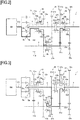
Fig. 1] Fig. 1 is a schematic diagram showing a dual clutch transmission according to a first embodiment of the invention. - [
Fig. 2] Fig. 2 is a diagram showing a power transmission path when a first gear is engaged in the dual clutch transmission shown inFig. 1 . - [
Fig. 3] Fig. 3 is a diagram showing a power transmission path when a second gear is engaged in the dual clutch transmission shown inFig. 1 . - [
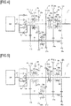
Fig. 4] Fig. 4 is a diagram showing a power transmission path when a third gear is engaged in the dual clutch transmission shown inFig. 1 . - [
Fig. 5] Fig. 5 is a diagram showing a power transmission path when a fourth gear is engaged in the dual clutch transmission shown inFig. 1 . - [
Fig. 6] Fig. 6 is a diagram showing a power transmission path when a fifth gear is engaged in the dual clutch transmission shown inFig. 1 . - [
Fig. 7] Fig. 7 is a diagram showing a power transmission path when a sixth gear is engaged in the dual clutch transmission shown inFig. 1 . - [
Fig. 8] Fig. 8 is a schematic diagram showing a dual clutch transmission according to a second embodiment of the invention. - [
Fig. 9] Fig. 9 is a schematic diagram showing a range gear mechanism. - [
Fig. 10] Fig. 10 is a diagram illustrating operations occurring when a first gear to a fifth gear are realized in the range gear mechanism shown inFig. 9 . - [
Fig. 11] Fig. 11 is a diagram illustrating operations occurring when a sixth gear to a tenth gear are realized in the range gear mechanism shown inFig. 9 . - Hereinafter, a first embodiment of the invention will be described in detail by reference to the drawings.
- A
dual clutch transmission 1 shown inFig. 1 is configured to be mounted on a vehicle. Specifically, thedual clutch transmission 1 is controlled functionally by an ECU (whose illustration is omitted) and includes afirst clutch 2, asecond clutch 3, afirst input shaft 4, asecond input shaft 5, acounter shaft 6, anoutput shaft 7, a first splittergear changing portion 10, a second splittergear changing portion 20, and anoutput portion 30. - The
first clutch 2 includes afirst pressure plate 2a and afirst clutch disc 2b. Thefirst pressure plate 2a is fixed to a crankshaft CS of an engine (a power source) EN and rotates together with the crankshaft CS. Thefirst clutch disc 2b is fixed to an input end side of thefirst input shaft 4 and rotates together with thefirst input shaft 4. Thefirst clutch 2 transmits power of the engine EN to thefirst input shaft 4 when thefirst pressure plate 2a moves in the direction of thefirst clutch disc 2b to thereby be brought into press contact with thefirst clutch disc 2b. - The
second clutch 3 is disposed concentrically with thefirst clutch 2. Specifically, thesecond clutch 3 includes asecond pressure plate 3a and asecond clutch disc 3b. Thesecond pressure plate 3a is fixed to the crankshaft CS of the engine EN and rotates together with the crankshaft CS. Thesecond clutch disc 3b is fixed to an input end side of thesecond input shaft 5 and rotates together with thesecond input shaft 5. Thesecond clutch 3 transmits the power of the engine EN to thesecond input shaft 5 when thesecond pressure plate 3a moves in the direction of thesecond clutch disc 3b to thereby be brought into press contact with thesecond clutch disc 3b. - The
first input shaft 4 is connected to the engine EN via thefirst clutch 2. Thisfirst input shaft 4 rotates as a result of the power of the engine EN being transmitted thereto. - The
second input shaft 5 is a hollow shaft through which thefirst input shaft 4 is inserted rotatably and is connected to the engine EN via thesecond clutch 3. Thissecond input shaft 5 rotates in the same direction as a direction in which thefirst input shaft 4 rotates as a result of the power of the engine EN being transmitted thereto. - The
counter shaft 6 is disposed parallel to thefirst input shaft 4 and thesecond input shaft 5. - The
output shaft 7 is disposed parallel to thecounter shaft 6 and coaxial with thefirst input shaft 4 and thesecond input shaft 5. - The first splitter
gear changing portion 10 includes a first high-speed gear train 11, a low-speed gear train 12 and afirst coupling mechanism 13. - The high-
speed gear train 11 includes afirst input gear 11a and afirst counter gear 11b. Thefirst input gear 11a is provided so that thesecond input shaft 5 is inserted therethrough rotatably and rotates about thesecond input shaft 5. Thefirst counter gear 11b is fixed to thecounter shaft 6 and rotates together with thefirst input gear 11a. Thisfirst counter gear 11b rotates about thecounter shaft 6 together with thecounter shaft 6 in an opposite direction to a direction in which thefirst input gear 11a rotates in association with the rotation of thefirst input gear 11a. - The low-
speed gear train 12 includes asecond input gear 12a and asecond counter gear 12b. Thesecond input gear 12a is provided so that thefirst input shaft 4 is inserted therethrough rotatably and rotates about thefirst input shaft 4. Thesecond counter gear 12b is fixed to thecounter shaft 6 and meshes with thesecond input gear 12a. Thissecond counter gear 12b rotates about thecounter shaft 6 together with thecounter shaft 6 in an opposite direction to a direction in which thesecond input gear 12a rotates in association with the rotation of thesecond input gear 12a. - The
first coupling mechanism 13 can couple thefirst input gear 11a and thesecond input gear 12a selectively to thesecond input shaft 5. Specifically, thefirst coupling mechanism 13 includes acoupling hub 13a, asleeve 13b, and dog gears 13c, 13d. Thecoupling hub 13a is fixed to an output end side of thesecond input shaft 5 and rotates together with thesecond input shaft 5. Thesleeve 13b is provided so as not to rotate but to move axially relative to thecoupling hub 13a. Thedog gear 13c is fixed to thefirst input gear 11a and rotates together with thefirst input gear 11a. Thedog gear 13d is fixed to thesecond input gear 12a and rotates together with thesecond input gear 12a. - The
first coupling mechanism 13 couples thefirst input gear 11a to thesecond input shaft 5 when thesleeve 13b moves in the direction of thedog gear 13c to thereby be brought into engagement with thedog gear 13c. As this occurs, thefirst input gear 11a can rotate together with thesecond input shaft 5. On the other hand, thefirst coupling mechanism 13 couples thesecond input gear 12a to thesecond input shaft 5 when thesleeve 13b moves in the direction of thedog gear 13d to thereby brought into engagement with thedog gear 13d. As this occurs, thesecond input gear 12a can rotate together with thesecond input shaft 5. - The second splitter
gear changing portion 20 includes an input/output gear train 21, asecond coupling mechanism 22 and athird coupling mechanism 23. - The input/output gear train 21 includes an input/output gear 21 a and a
third counter gear 21b. The input/output gear 21a is fixed to thefirst input shaft 4. This input/output gear 21 a rotates about thefirst input shaft 4 together with thefirst input shaft 4. Thethird counter gear 21b is provided so that thecounter shaft 6 is inserted therethrough rotatably and thethird counter gear 21b meshes with the input/output gear 21a. Thisthird counter gear 21b rotates about thecounter shaft 6 in an opposite direction to a direction in which the input/output gear 21 a rotates in association with the rotation of the input/output gear 21a. - The
second coupling mechanism 22 can couple theoutput shaft 7 to thefirst input shaft 4. Specifically, thesecond coupling mechanism 22 includes acoupling hub 22a, asleeve 22b, and adog gear 22c. Thecoupling hub 22a is fixed to an input end side of theoutput shaft 7 and rotates together with theoutput shaft 7. Thesleeve 22b is provided so as not to rotate but to move axially relative to thecoupling hub 22a. Thedog gear 22c is fixed to an output end side of thefirst input shaft 4 and rotates together with thefirst input shaft 4. - The
second coupling mechanism 22 couples theoutput shaft 7 to thefirst input shaft 4 when thesleeve 22b moves in the direction of thedog gear 22c to thereby be brought into engagement with thedog gear 22c. As this occurs, theoutput shaft 7 can rotate together with thefirst input shaft 4. - The
third coupling mechanism 23 can couple thethird counter gear 21b to thecounter shaft 6. Specifically, thethird coupling mechanism 23 includes acoupling hub 23a, asleeve 23b, and adog gear 23c. Thecoupling hub 23a is fixed thecounter shaft 6 and rotates together with thecounter shaft 6. Thesleeve 23b is provided so as not to rotate but to move axially relative to thecoupling hub 23a. Thedog gear 23c is fixed to thethird counter gear 21b and rotates together with thethird counter gear 21b. - The
third coupling mechanism 23 couples thethird counter gear 21b to thecounter shaft 6 when thesleeve 23b moves in the direction of thedog gear 23c to be brought into engagement with thedog gear 23c. As this occurs, thethird counter gear 21b can rotate together with thecounter shaft 6. - The
output portion 30 includes aforward gear train 31, areverse gear train 32 and afourth coupling mechanism 33. - The
forward gear train 31 includes afourth counter gear 31 a and aforward output gear 31b. Thefourth counter gear 31a is fixed to thecounter shaft 6. Thefourth counter gear 31 a rotates about thecounter shaft 6 together with thecounter shaft 6. Theforward output gear 31b is provided so that theoutput shaft 7 is inserted therethrough rotatably and theforward output gear 31b meshes with thefourth counter gear 31a. Thisforward output gear 31b rotates about theoutput shaft 7 in an opposite direction to a direction in which thefourth counter gear 31 a rotates in association with the rotation of thefourth counter gear 31a. - The
reverse gear train 32 includes afifth counter gear 32a, anidler gear 32b and areverse output gear 32c. Thefifth counter gear 32a is fixed to thecounter shaft 6. Thefifth counter gear 32a rotates about thecounter shaft 6 together with thecounter shaft 6. Theidler gear 32b is provided so as not only to be attached to a shaft (whose illustration is omitted) parallel to thecounter shaft 6 but also to mesh with thefifth counter gear 32a. Thisidler gear 32b rotates in an opposite direction to a direction in which thefifth counter gear 32a rotates in association with the rotation of thefifth counter gear 32a. Thereverse output gear 32c is provided so that theoutput shaft 7 is inserted therethrough rotatably and thereverse output gear 32c meshes with theidler gear 32b. Thereverse output gear 32c rotates about theoutput shaft 7 in an opposite direction to a direction in which theidler gear 32b rotates and in the same direction as a direction in which thefifth counter gear 32a rotates in association with the rotation of theidler gear 32b. A relationship among thefifth counter gear 32a, theidler gear 32b and thereverse output gear 32c in the drawings is drawn according to the conventional practice and differs from a relationship in reality. - The
fourth coupling mechanism 33 can couple theforward output gear 31b and thereverse output gear 32c selectively to theoutput shaft 7. Specifically, thefourth coupling mechanism 33 includes acoupling hub 33a, asleeve 33b, and dog gears 33c, 33d. Thecoupling hub 33a is fixed to anoutput shaft 7 and rotates together with theoutput shaft 7. Thesleeve 33b is provided so as not to be fixed but to move axially relative to thecoupling hub 33a. Thedog gear 33c is fixed to theforward output gear 31b and rotates together with theforward output gear 31b. Thedog gear 33d is fixed to thereverse output gear 32c and rotates together with thereverse output gear 32c. - The
fourth coupling mechanism 33 couples theforward output gear 31b to theoutput shaft 7 when thesleeve 33b moves in the direction of thedog gear 33c to thereby be brought into engagement with thedog gear 33c. As this occurs, theforward output gear 31b can rotate together with theoutput shaft 7. On the other hand, thefourth coupling mechanism 33 couples thereverse output gear 32c to theoutput shaft 7 when thesleeve 33b moves in the direction of thedog gear 33d to thereby be brought into engagement with thedog gear 33d. As this occurs, thereverse output gear 32c can rotate together with theoutput shaft 7. - Next, power transmission paths of the dual
clutch transmission 1 will be described. - When a first gear is engaged as shown in
Fig. 2 , in the dualclutch transmission 1, thesecond input gear 12a is coupled to thesecond input shaft 5 by thefirst coupling mechanism 13, theforward output gear 31b is coupled to theoutput shaft 7 by thefourth coupling mechanism 33, and thesecond clutch 3 is applied. This allows the power of the engine EN to be transmitted sequentially from thesecond clutch 3 to thesecond input shaft 5, the low-speed gear train 12, thecounter shaft 6, theforward gear train 31 and theoutput shaft 7 in that order. - When a second gear is engaged as shown in
Fig. 3 , in the dualclutch transmission 1, thethird counter gear 21b is coupled to thecounter shaft 6 by thethird coupling mechanism 23, theforward output gear 31b is coupled to theoutput shaft 7 by thefourth coupling mechanism 33, and thefirst clutch 2 is applied. This allows the power of the engine EN to be transmitted sequentially from thefirst clutch 2 to thefirst input shaft 4, the input/output gear train 21, thecounter shaft 6, theforward gear train 31 and theoutput shaft 7 in that order. - When a third gear is engaged as shown in
Fig. 4 , in the dualclutch transmission 1, thefirst input gear 11a is coupled to thesecond input shaft 5 by thefirst coupling mechanism 13, theforward output gear 31b is coupled to theoutput shaft 7 by thefourth coupling mechanism 33, and thesecond clutch 3 is applied. This allows the power of the engine EN to be transmitted sequentially from thesecond clutch 3 to thesecond input shaft 5, the high-speed gear train 11, thecounter shaft 6, theforward gear train 31 and theoutput shaft 7 in that order. - When a fourth gear is engaged as shown in
Fig. 5 , in the dualclutch transmission 1, theoutput shaft 7 is coupled to thefirst input shaft 4 by thesecond coupling mechanism 22 and thefirst clutch 2 is applied. This allows the power of the engine EN to be transmitted sequentially from thefirst clutch 2 to thefirst input shaft 4 and theoutput shaft 7 in that order. - When a fifth gear is engaged as shown in
Fig. 6 , in the dualclutch transmission 1, thesecond input gear 12a is coupled to thesecond input shaft 5 by thefirst coupling mechanism 13, theoutput shaft 7 is coupled to thefirst input shaft 4 by thesecond coupling mechanism 22, thethird counter gear 21b is coupled to thecounter shaft 6 by thethird coupling mechanism 23, and thesecond clutch 3 is applied. This allows the power of the engine EN to be transmitted sequentially from thesecond clutch 3 to thesecond input shaft 4, the low-speed gear train 12, thecounter shaft 6, the input/output gear train 21, thefirst input shaft 4 and theoutput shaft 7 in that order. - When a sixth gear is engaged as shown in
Fig. 7 , in the dualclutch transmission 1, thefirst input gear 11a is coupled to thesecond input shaft 5 by thefirst coupling mechanism 13, theoutput shaft 7 is coupled to thefirst input shaft 4 by thesecond coupling mechanism 22, thethird counter gear 21b is coupled to thecounter shaft 6 by the third connectingmechanism 23, and thesecond clutch 3 is applied. This allows the power of the engine EN to be transmitted sequentially from thesecond clutch 3 to thesecond input shaft 4, the high-speed gear train 11, thecounter shaft 6, the input/output gear train 21, thefirst input shaft 4, and theoutput shaft 7 in that order. - According to this embodiment, the
second input gear 12a, the input/output gear 21 a and thefirst input gear 11a are made use of sequentially, and theforward output gear 31b is made use of as required. This realizes three gears to be changed on a low-speed side. - In addition, the
second input gear 12a and thefirst input gear 11 a are made use of sequentially, and the input/output gear 21 a is made use of as required. This realizes three gears to be changed on the high-speed side, including the engagement of the fourth gear where thefirst input shaft 4 is coupled directly to theoutput shaft 7. - Consequently, it is possible to increase the number of gears to be changed without increasing the number of gears. In addition, no thrust force is generated in each of the gears, and there is imposed no restriction on the number of gears.
- Next, a second embodiment of the invention will be described in detail by reference to the drawings. A dual
clutch transmission 40 according to the second embodiment is such that arange gear mechanism 41 is added to the dualclutch transmission 1 according to the first embodiment, and like reference numerals will be given to like configurations to those of the first embodiment, and the description thereof will be omitted. - The dual
clutch transmission 40 shown inFig. 8 includes therange gear mechanism 41. - The
range gear mechanism 41 shown inFigs. 8 and9 includes acase 42, asun gear 43, a plurality ofplanetary gears 44, aplanetary carrier 45, anrange output shaft 46, anouter gear 47, a fifth coupling mechanism (whose illustration is omitted) and a sixth coupling mechanism (whose illustration is omitted). - An output end side of an
output shaft 7 is inserted through thecase 42 rotatably. - The
sun gear 43 is fixed to theoutput shaft 7 inside thecase 42. Thesun gear 43 rotates about theoutput shaft 7 together with theoutput shaft 7. - The plurality of
planetary gears 44 are provided so as to mesh with thesun gear 43 and can revolve around thesun gear 43. -
Rotational shafts 44a of theplanetary gears 44 are fixed to theplanetary carrier 45. - The
range output shaft 46 is fixed to theplanetary carrier 45 and is disposed so as to be coaxial with theoutput shaft 7. Thisrange output shaft 46 rotates together with theplanetary carrier 45. - The
outer gear 47 is provided so as not only to surround the plurality ofplanetary gears 44 altogether but also to mesh individually with the plurality ofplanetary gears 44. - The fifth coupling mechanism (whose illustration is omitted) can couple the
outer gear 47 to thecase 42. - The sixth coupling mechanism (whose illustration is omitted) can couple the
planetary carrier 45 or therange output shaft 46 to theoutput shaft 7. - The details of the
range gear mechanism 41 are similar to those of the mechanism disclosed inJP-B-06-074828 JP-B-06-074828 - Next, the operation of the
range gear mechanism 41 will be described. - When a first gear to a fifth gear are engaged as shown in
Fig. 10 , in therange gear mechanism 41, theouter gear 47 is coupled to thecase 42 by the fifth coupling mechanism (whose illustration is omitted). As this occurs, thesun gear 43 which is fixed to theoutput shaft 7 rotates together with theoutput shaft 7. The plurality ofplanetary gears 43 which mesh with thesun gear 43 mesh individually with theouter gear 47 which is coupled to thecase 42 so as not to rotate. Thus, theplanetary gears 43 revolve around thesun gear 43 in the same direction as a direction in which thesun gear 43 rotates while rotating on their own shafts in an opposite direction to the direction in which thesun gear 43 rotates in association with the rotation of thesun gear 43. Theplanetary carrier 45, to which therotational shafts 44a of the plurality ofplanetary gears 44 are fixed, rotates in the same direction as the direction in which theplanetary gears 44 revolve around thesun gear 43 as theplanetary gears 44 revolve around. Therange output shaft 46 which is fixed to theplanetary carrier 45 rotates together with theplanetary carrier 45. This causes therange output shaft 46 to rotate at lower speeds than a speed at which theoutput shaft 7 rotates. - When a sixth gear to a tenth gear are engaged as shown in
Fig. 11 , in therange gear mechanism 41, theplanetary carrier 45 or therange output shaft 46 is coupled to theoutput shaft 7 by the sixth coupling mechanism (whose illustration is omitted). As this occurs, therange output shaft 46 rotates together with theoutput shaft 7. This causes therange output shaft 46 to rotate at an equal speed to the speed at which theoutput shaft 7 rotates. - The power transmission paths to the
output shaft 7 in the dualclutch transmission 40 which are realized when the first gear to the fifth gear are engaged are the same as the power transmission paths to theoutput shaft 7 in the dualclutch transmission 1 of the first embodiment which are realized when the first gear to the fifth gear are engaged, and the power transmission paths realized in the dualclutch transmission 40 when the sixth gear to the tenth gear are engaged are the same as the power transmission paths realized in the dualclutch transmission 1 when the first gear to the fifth gear are engaged. - According to this embodiment, the first gear to the fifth gear are realized by causing the
range output shaft 46 to rotate at the lower speeds than the speed at which theoutput shaft 7 rotates. - In addition, the sixth gear to the tenth gear are realized by connecting the
output shaft 7 directly to therange output shaft 46. - Consequently, it is possible to increase further the number of gears to be changed without increasing the number of gears.
- Thus, while the embodiments to which the invention made by the inventor is applied have been described heretofore, the invention is not limited at all by the description and the drawings which make up part of the disclosure of the invention based on the embodiments. Namely, other embodiments, examples and operating techniques which are made based on the embodiments described herein by those skilled in the art to which the invention pertains should all, of course, be included in the scope of the invention.
-
- 1, 40
- dual clutch transmission
- 2
- first clutch
- 3
- second clutch
- 4
- first input shaft
- 5
- second input shaft
- 6
- counter shaft
- 7
- output shaft
- 10
- first splitter gear changing portion
- 11a
- first input gear
- 11b
- first counter gear
- 12a
- second input gear
- 12b
- second counter gear
- 13
- first coupling mechanism
- 20
- second splitter gear changing portion
- 21a
- input/output gear
- 21b
- third counter gear
- 22
- second coupling mechanism
- 23
- third coupling mechanism
- 30
- output portion
- 31a
- fourth counter gear
- 31b
- forward output gear (output gear)
- 33
- fourth coupling mechanism
- 41
- range gear mechanism
- 42
- case
- 43
- sun gear
- 44
- planetary gear
- 44a
- rotational shaft
- 45
- planetary carrier
- 46
- range output shaft
- 47
- outer gear
- EN
- engine (power source)
Claims (2)
- A dual clutch transmission comprising:a first clutch;a second clutch that is disposed concentrically with the first clutch;a first input shaft that is connected to a power source via the first clutch;a second input shaft that is a hollow shaft through which the first input shaft is inserted rotatably, the second input shaft being connected to the power source via the second clutch;a counter shaft that is disposed parallel to the first input shaft and the second input shaft;an output shaft that is disposed parallel to the counter shaft and coaxial with the first input shaft and the second input shaft;a first splitter gear changing portion comprising:a first input gear through which the second input shaft is inserted rotatably;a first counter gear that is fixed to the counter shaft and meshes with the first input gear;a second input gear through which the first input shaft is inserted rotatably;a second counter gear that is fixed to the counter shaft and meshes with the second input gear; anda first coupling mechanism configured to couple the first input gear and the second input gear selectively to the second input shaft;a second splitter gear changing portion comprising:an input/output gear that is fixed to the first input shaft;a third counter gear through which the counter shaft is inserted rotatably, the third counter gear meshing with the input/output gear;a second coupling mechanism configured to couple the output shaft to the first input shaft; anda third coupling mechanism configured to couple the third counter gear to the counter shaft; andan output portion comprising:a fourth counter gear that is fixed to the counter shaft;an output gear through which the output shaft is inserted rotatably, the output gear meshing with the fourth counter gear; anda fourth coupling mechanism configured to couple the output gear to the output shaft.
- The dual clutch transmission according to claim 1, wherein the dual clutch transmission comprises:a range mechanism comprising:a case into which the output shaft is inserted rotatably;a sun gear that is fixed to the output shaft inside the case;a planetary gear that meshes with the sun gear and configured to revolve around the sun gear;a planetary carrier to which a rotational shaft of the planetary gear is fixed;a range output shaft that is fixed to the planetary carrier so as to be disposed coaxial with the output shaft;an outer gear that meshes with the planetary gear;a fifth coupling mechanism configured to couple the outer gear to the case; anda sixth coupling mechanism configured to couple the planetary carrier or the range output shaft to the output shaft.
Applications Claiming Priority (2)
| Application Number | Priority Date | Filing Date | Title |
|---|---|---|---|
| JP2014184469A JP2016056894A (en) | 2014-09-10 | 2014-09-10 | Dual clutch transmission |
| PCT/JP2015/075641 WO2016039389A1 (en) | 2014-09-10 | 2015-09-09 | Dual clutch transmission |
Publications (3)
| Publication Number | Publication Date |
|---|---|
| EP3193042A1 true EP3193042A1 (en) | 2017-07-19 |
| EP3193042A4 EP3193042A4 (en) | 2018-06-06 |
| EP3193042B1 EP3193042B1 (en) | 2020-11-11 |
Family
ID=55459133
Family Applications (1)
| Application Number | Title | Priority Date | Filing Date |
|---|---|---|---|
| EP15840795.7A Active EP3193042B1 (en) | 2014-09-10 | 2015-09-09 | Dual clutch transmission |
Country Status (5)
| Country | Link |
|---|---|
| US (1) | US9989134B2 (en) |
| EP (1) | EP3193042B1 (en) |
| JP (1) | JP2016056894A (en) |
| CN (1) | CN106687713B (en) |
| WO (1) | WO2016039389A1 (en) |
Families Citing this family (5)
| Publication number | Priority date | Publication date | Assignee | Title |
|---|---|---|---|---|
| JP2016053378A (en) * | 2014-09-03 | 2016-04-14 | いすゞ自動車株式会社 | Dual clutch transmission |
| CN107489740B (en) * | 2017-09-04 | 2019-06-18 | 北京理工大学 | Longitudinal seven-speed dual-clutch transmission |
| CN110182047A (en) * | 2019-06-13 | 2019-08-30 | 淮阴工学院 | A kind of transmission integrated system of electric powered motor |
| CN115773344A (en) * | 2022-11-18 | 2023-03-10 | 扬州工业职业技术学院 | Automatic loading transmission and automatic loading transmission method |
| CN119084544B (en) * | 2024-08-08 | 2026-03-17 | 麦格纳动力总成(江西)有限公司 | A transmission structure and a gearbox |
Family Cites Families (17)
| Publication number | Priority date | Publication date | Assignee | Title |
|---|---|---|---|---|
| SE435831B (en) | 1982-06-07 | 1984-10-22 | Volvo Ab | RANGEVEXELLADA FOR MOTOR VEHICLES |
| JPS60231048A (en) * | 1984-04-28 | 1985-11-16 | Mazda Motor Corp | Geared transmission |
| JPS61274147A (en) | 1985-05-28 | 1986-12-04 | Mazda Motor Corp | Gear type speed changer |
| US20030232689A1 (en) * | 2002-06-13 | 2003-12-18 | Raymond James Haka | Dual input clutch transmission having synchronizers for establishing speed ratios |
| JP4304051B2 (en) | 2003-11-12 | 2009-07-29 | 本田技研工業株式会社 | transmission |
| DE102004022413B4 (en) * | 2004-05-06 | 2010-04-15 | Zf Friedrichshafen Ag | Double clutch |
| DE102006015661A1 (en) * | 2006-04-04 | 2007-10-11 | Daimlerchrysler Ag | Powershift transmission for a commercial vehicle |
| DE102007029634A1 (en) | 2007-06-26 | 2009-01-08 | Daimler Ag | Gear shift transmission |
| US7896770B2 (en) * | 2007-08-01 | 2011-03-01 | GM Global Technology Operations LLC | Multi-speed transmission |
| DE102007038175A1 (en) * | 2007-08-13 | 2009-02-19 | Magna Powertrain Ag & Co Kg | manual transmission |
| US8601892B2 (en) * | 2010-01-12 | 2013-12-10 | Borgwarner Inc. | DCT transmission utilizing a two axis chain |
| JP5924774B2 (en) | 2011-01-28 | 2016-05-25 | 株式会社ユニバンス | Dual clutch transmission for vehicle |
| CN202125579U (en) * | 2011-01-30 | 2012-01-25 | 长城汽车股份有限公司 | Double-clutch type automatic speed changer |
| US9162667B2 (en) * | 2012-06-05 | 2015-10-20 | Hyundai Motor Company | Power transmitting apparatus for vehicle |
| DE102012211531A1 (en) * | 2012-07-03 | 2014-01-09 | Zf Friedrichshafen Ag | Gearbox with switchable variator |
| DE102013200196A1 (en) * | 2013-01-09 | 2014-07-10 | Zf Friedrichshafen Ag | Transmission for a motor vehicle |
| CN103195879A (en) * | 2013-04-02 | 2013-07-10 | 天津市松正电动汽车技术股份有限公司 | Two speed transmission for hybrid power system |
-
2014
- 2014-09-10 JP JP2014184469A patent/JP2016056894A/en active Pending
-
2015
- 2015-09-09 US US15/510,550 patent/US9989134B2/en active Active
- 2015-09-09 EP EP15840795.7A patent/EP3193042B1/en active Active
- 2015-09-09 CN CN201580048198.3A patent/CN106687713B/en active Active
- 2015-09-09 WO PCT/JP2015/075641 patent/WO2016039389A1/en not_active Ceased
Also Published As
| Publication number | Publication date |
|---|---|
| WO2016039389A1 (en) | 2016-03-17 |
| JP2016056894A (en) | 2016-04-21 |
| CN106687713B (en) | 2019-03-01 |
| EP3193042A4 (en) | 2018-06-06 |
| CN106687713A (en) | 2017-05-17 |
| US9989134B2 (en) | 2018-06-05 |
| US20170261081A1 (en) | 2017-09-14 |
| EP3193042B1 (en) | 2020-11-11 |
Similar Documents
| Publication | Publication Date | Title |
|---|---|---|
| US8801566B2 (en) | Quad-clutch multi-speed transmission | |
| EP3193042B1 (en) | Dual clutch transmission | |
| US10066701B2 (en) | Multi-speed transmission | |
| US11187310B2 (en) | Gear mechanism, use of a gear mechanism and method for a gear mechanism | |
| US9133911B2 (en) | Double clutch transmission of vehicle | |
| WO2013146029A1 (en) | Automatic transmission device | |
| JP5860138B2 (en) | Automatic transmission device | |
| WO2013146032A1 (en) | Automatic transmission device | |
| US9145960B2 (en) | Triple clutch multi-speed transmission | |
| EP2847494B1 (en) | Reversing double - flow gearbox arrangement, mainly for motor vehicles and construction machines, with two branches of output flow | |
| JP5860139B2 (en) | Automatic transmission device | |
| JPWO2013146030A1 (en) | Automatic transmission device | |
| US11867269B2 (en) | Shift group for power shift transmission | |
| US20160131223A1 (en) | Transmission with dual input and reduced number of lay shafts | |
| US20140162833A1 (en) | Planetary gear train of automatic transmission for vehicle | |
| JPWO2013146025A1 (en) | Automatic transmission device | |
| CN108351005B (en) | Gearbox unit for agricultural vehicles with a wide speed range | |
| JPWO2013146026A1 (en) | Automatic transmission device | |
| EP3190312A1 (en) | Dual clutch transmission | |
| CN105008767A (en) | Multi-stage planetary transmission | |
| US11846342B2 (en) | Six-speed front-transverse double-clutch transmission with third counter shaft | |
| US8622867B1 (en) | Differential with torque distribution | |
| JP2017172717A (en) | Automatic transmission | |
| CN105443683B (en) | Eight-speed automatic transmission, car | |
| CN103883685A (en) | Mechanical transmission |
Legal Events
| Date | Code | Title | Description |
|---|---|---|---|
| STAA | Information on the status of an ep patent application or granted ep patent |
Free format text: STATUS: THE INTERNATIONAL PUBLICATION HAS BEEN MADE |
|
| PUAI | Public reference made under article 153(3) epc to a published international application that has entered the european phase |
Free format text: ORIGINAL CODE: 0009012 |
|
| STAA | Information on the status of an ep patent application or granted ep patent |
Free format text: STATUS: REQUEST FOR EXAMINATION WAS MADE |
|
| 17P | Request for examination filed |
Effective date: 20170410 |
|
| AK | Designated contracting states |
Kind code of ref document: A1 Designated state(s): AL AT BE BG CH CY CZ DE DK EE ES FI FR GB GR HR HU IE IS IT LI LT LU LV MC MK MT NL NO PL PT RO RS SE SI SK SM TR |
|
| AX | Request for extension of the european patent |
Extension state: BA ME |
|
| DAV | Request for validation of the european patent (deleted) | ||
| DAX | Request for extension of the european patent (deleted) | ||
| A4 | Supplementary search report drawn up and despatched |
Effective date: 20180508 |
|
| RIC1 | Information provided on ipc code assigned before grant |
Ipc: F16H 3/091 20060101AFI20180502BHEP Ipc: F16H 3/48 20060101ALI20180502BHEP Ipc: F16H 37/04 20060101ALI20180502BHEP |
|
| REG | Reference to a national code |
Ref country code: DE Ref legal event code: R079 Ref document number: 602015061970 Country of ref document: DE Free format text: PREVIOUS MAIN CLASS: F16H0003091000 Ipc: F16H0003000000 |
|
| GRAP | Despatch of communication of intention to grant a patent |
Free format text: ORIGINAL CODE: EPIDOSNIGR1 |
|
| STAA | Information on the status of an ep patent application or granted ep patent |
Free format text: STATUS: GRANT OF PATENT IS INTENDED |
|
| RIC1 | Information provided on ipc code assigned before grant |
Ipc: F16H 3/091 20060101ALN20200409BHEP Ipc: F16H 3/00 20060101AFI20200409BHEP Ipc: F16H 37/04 20060101ALN20200409BHEP |
|
| INTG | Intention to grant announced |
Effective date: 20200424 |
|
| GRAS | Grant fee paid |
Free format text: ORIGINAL CODE: EPIDOSNIGR3 |
|
| GRAA | (expected) grant |
Free format text: ORIGINAL CODE: 0009210 |
|
| STAA | Information on the status of an ep patent application or granted ep patent |
Free format text: STATUS: THE PATENT HAS BEEN GRANTED |
|
| AK | Designated contracting states |
Kind code of ref document: B1 Designated state(s): AL AT BE BG CH CY CZ DE DK EE ES FI FR GB GR HR HU IE IS IT LI LT LU LV MC MK MT NL NO PL PT RO RS SE SI SK SM TR |
|
| REG | Reference to a national code |
Ref country code: GB Ref legal event code: FG4D |
|
| REG | Reference to a national code |
Ref country code: CH Ref legal event code: EP |
|
| REG | Reference to a national code |
Ref country code: AT Ref legal event code: REF Ref document number: 1333786 Country of ref document: AT Kind code of ref document: T Effective date: 20201115 |
|
| REG | Reference to a national code |
Ref country code: DE Ref legal event code: R096 Ref document number: 602015061970 Country of ref document: DE |
|
| REG | Reference to a national code |
Ref country code: IE Ref legal event code: FG4D |
|
| REG | Reference to a national code |
Ref country code: NL Ref legal event code: MP Effective date: 20201111 |
|
| REG | Reference to a national code |
Ref country code: AT Ref legal event code: MK05 Ref document number: 1333786 Country of ref document: AT Kind code of ref document: T Effective date: 20201111 |
|
| PG25 | Lapsed in a contracting state [announced via postgrant information from national office to epo] |
Ref country code: PT Free format text: LAPSE BECAUSE OF FAILURE TO SUBMIT A TRANSLATION OF THE DESCRIPTION OR TO PAY THE FEE WITHIN THE PRESCRIBED TIME-LIMIT Effective date: 20210311 Ref country code: RS Free format text: LAPSE BECAUSE OF FAILURE TO SUBMIT A TRANSLATION OF THE DESCRIPTION OR TO PAY THE FEE WITHIN THE PRESCRIBED TIME-LIMIT Effective date: 20201111 Ref country code: FI Free format text: LAPSE BECAUSE OF FAILURE TO SUBMIT A TRANSLATION OF THE DESCRIPTION OR TO PAY THE FEE WITHIN THE PRESCRIBED TIME-LIMIT Effective date: 20201111 Ref country code: NO Free format text: LAPSE BECAUSE OF FAILURE TO SUBMIT A TRANSLATION OF THE DESCRIPTION OR TO PAY THE FEE WITHIN THE PRESCRIBED TIME-LIMIT Effective date: 20210211 Ref country code: GR Free format text: LAPSE BECAUSE OF FAILURE TO SUBMIT A TRANSLATION OF THE DESCRIPTION OR TO PAY THE FEE WITHIN THE PRESCRIBED TIME-LIMIT Effective date: 20210212 |
|
| PG25 | Lapsed in a contracting state [announced via postgrant information from national office to epo] |
Ref country code: AT Free format text: LAPSE BECAUSE OF FAILURE TO SUBMIT A TRANSLATION OF THE DESCRIPTION OR TO PAY THE FEE WITHIN THE PRESCRIBED TIME-LIMIT Effective date: 20201111 Ref country code: BG Free format text: LAPSE BECAUSE OF FAILURE TO SUBMIT A TRANSLATION OF THE DESCRIPTION OR TO PAY THE FEE WITHIN THE PRESCRIBED TIME-LIMIT Effective date: 20210211 Ref country code: IS Free format text: LAPSE BECAUSE OF FAILURE TO SUBMIT A TRANSLATION OF THE DESCRIPTION OR TO PAY THE FEE WITHIN THE PRESCRIBED TIME-LIMIT Effective date: 20210311 Ref country code: LV Free format text: LAPSE BECAUSE OF FAILURE TO SUBMIT A TRANSLATION OF THE DESCRIPTION OR TO PAY THE FEE WITHIN THE PRESCRIBED TIME-LIMIT Effective date: 20201111 Ref country code: PL Free format text: LAPSE BECAUSE OF FAILURE TO SUBMIT A TRANSLATION OF THE DESCRIPTION OR TO PAY THE FEE WITHIN THE PRESCRIBED TIME-LIMIT Effective date: 20201111 Ref country code: SE Free format text: LAPSE BECAUSE OF FAILURE TO SUBMIT A TRANSLATION OF THE DESCRIPTION OR TO PAY THE FEE WITHIN THE PRESCRIBED TIME-LIMIT Effective date: 20201111 |
|
| REG | Reference to a national code |
Ref country code: LT Ref legal event code: MG9D |
|
| PG25 | Lapsed in a contracting state [announced via postgrant information from national office to epo] |
Ref country code: HR Free format text: LAPSE BECAUSE OF FAILURE TO SUBMIT A TRANSLATION OF THE DESCRIPTION OR TO PAY THE FEE WITHIN THE PRESCRIBED TIME-LIMIT Effective date: 20201111 |
|
| PG25 | Lapsed in a contracting state [announced via postgrant information from national office to epo] |
Ref country code: SM Free format text: LAPSE BECAUSE OF FAILURE TO SUBMIT A TRANSLATION OF THE DESCRIPTION OR TO PAY THE FEE WITHIN THE PRESCRIBED TIME-LIMIT Effective date: 20201111 Ref country code: CZ Free format text: LAPSE BECAUSE OF FAILURE TO SUBMIT A TRANSLATION OF THE DESCRIPTION OR TO PAY THE FEE WITHIN THE PRESCRIBED TIME-LIMIT Effective date: 20201111 Ref country code: EE Free format text: LAPSE BECAUSE OF FAILURE TO SUBMIT A TRANSLATION OF THE DESCRIPTION OR TO PAY THE FEE WITHIN THE PRESCRIBED TIME-LIMIT Effective date: 20201111 Ref country code: RO Free format text: LAPSE BECAUSE OF FAILURE TO SUBMIT A TRANSLATION OF THE DESCRIPTION OR TO PAY THE FEE WITHIN THE PRESCRIBED TIME-LIMIT Effective date: 20201111 Ref country code: SK Free format text: LAPSE BECAUSE OF FAILURE TO SUBMIT A TRANSLATION OF THE DESCRIPTION OR TO PAY THE FEE WITHIN THE PRESCRIBED TIME-LIMIT Effective date: 20201111 Ref country code: LT Free format text: LAPSE BECAUSE OF FAILURE TO SUBMIT A TRANSLATION OF THE DESCRIPTION OR TO PAY THE FEE WITHIN THE PRESCRIBED TIME-LIMIT Effective date: 20201111 |
|
| REG | Reference to a national code |
Ref country code: DE Ref legal event code: R097 Ref document number: 602015061970 Country of ref document: DE |
|
| PG25 | Lapsed in a contracting state [announced via postgrant information from national office to epo] |
Ref country code: DK Free format text: LAPSE BECAUSE OF FAILURE TO SUBMIT A TRANSLATION OF THE DESCRIPTION OR TO PAY THE FEE WITHIN THE PRESCRIBED TIME-LIMIT Effective date: 20201111 |
|
| PLBE | No opposition filed within time limit |
Free format text: ORIGINAL CODE: 0009261 |
|
| STAA | Information on the status of an ep patent application or granted ep patent |
Free format text: STATUS: NO OPPOSITION FILED WITHIN TIME LIMIT |
|
| 26N | No opposition filed |
Effective date: 20210812 |
|
| PG25 | Lapsed in a contracting state [announced via postgrant information from national office to epo] |
Ref country code: NL Free format text: LAPSE BECAUSE OF FAILURE TO SUBMIT A TRANSLATION OF THE DESCRIPTION OR TO PAY THE FEE WITHIN THE PRESCRIBED TIME-LIMIT Effective date: 20201111 Ref country code: IT Free format text: LAPSE BECAUSE OF FAILURE TO SUBMIT A TRANSLATION OF THE DESCRIPTION OR TO PAY THE FEE WITHIN THE PRESCRIBED TIME-LIMIT Effective date: 20201111 Ref country code: AL Free format text: LAPSE BECAUSE OF FAILURE TO SUBMIT A TRANSLATION OF THE DESCRIPTION OR TO PAY THE FEE WITHIN THE PRESCRIBED TIME-LIMIT Effective date: 20201111 |
|
| PGFP | Annual fee paid to national office [announced via postgrant information from national office to epo] |
Ref country code: FR Payment date: 20210812 Year of fee payment: 7 |
|
| PG25 | Lapsed in a contracting state [announced via postgrant information from national office to epo] |
Ref country code: SI Free format text: LAPSE BECAUSE OF FAILURE TO SUBMIT A TRANSLATION OF THE DESCRIPTION OR TO PAY THE FEE WITHIN THE PRESCRIBED TIME-LIMIT Effective date: 20201111 |
|
| PGFP | Annual fee paid to national office [announced via postgrant information from national office to epo] |
Ref country code: GB Payment date: 20210805 Year of fee payment: 7 |
|
| PG25 | Lapsed in a contracting state [announced via postgrant information from national office to epo] |
Ref country code: ES Free format text: LAPSE BECAUSE OF FAILURE TO SUBMIT A TRANSLATION OF THE DESCRIPTION OR TO PAY THE FEE WITHIN THE PRESCRIBED TIME-LIMIT Effective date: 20201111 |
|
| REG | Reference to a national code |
Ref country code: CH Ref legal event code: PL |
|
| REG | Reference to a national code |
Ref country code: BE Ref legal event code: MM Effective date: 20210930 |
|
| PG25 | Lapsed in a contracting state [announced via postgrant information from national office to epo] |
Ref country code: IS Free format text: LAPSE BECAUSE OF FAILURE TO SUBMIT A TRANSLATION OF THE DESCRIPTION OR TO PAY THE FEE WITHIN THE PRESCRIBED TIME-LIMIT Effective date: 20210311 Ref country code: MC Free format text: LAPSE BECAUSE OF FAILURE TO SUBMIT A TRANSLATION OF THE DESCRIPTION OR TO PAY THE FEE WITHIN THE PRESCRIBED TIME-LIMIT Effective date: 20201111 |
|
| PG25 | Lapsed in a contracting state [announced via postgrant information from national office to epo] |
Ref country code: LU Free format text: LAPSE BECAUSE OF NON-PAYMENT OF DUE FEES Effective date: 20210909 Ref country code: IE Free format text: LAPSE BECAUSE OF NON-PAYMENT OF DUE FEES Effective date: 20210909 Ref country code: BE Free format text: LAPSE BECAUSE OF NON-PAYMENT OF DUE FEES Effective date: 20210930 |
|
| PG25 | Lapsed in a contracting state [announced via postgrant information from national office to epo] |
Ref country code: LI Free format text: LAPSE BECAUSE OF NON-PAYMENT OF DUE FEES Effective date: 20210930 Ref country code: CH Free format text: LAPSE BECAUSE OF NON-PAYMENT OF DUE FEES Effective date: 20210930 |
|
| GBPC | Gb: european patent ceased through non-payment of renewal fee |
Effective date: 20220909 |
|
| PG25 | Lapsed in a contracting state [announced via postgrant information from national office to epo] |
Ref country code: HU Free format text: LAPSE BECAUSE OF FAILURE TO SUBMIT A TRANSLATION OF THE DESCRIPTION OR TO PAY THE FEE WITHIN THE PRESCRIBED TIME-LIMIT; INVALID AB INITIO Effective date: 20150909 |
|
| PG25 | Lapsed in a contracting state [announced via postgrant information from national office to epo] |
Ref country code: CY Free format text: LAPSE BECAUSE OF FAILURE TO SUBMIT A TRANSLATION OF THE DESCRIPTION OR TO PAY THE FEE WITHIN THE PRESCRIBED TIME-LIMIT Effective date: 20201111 |
|
| PG25 | Lapsed in a contracting state [announced via postgrant information from national office to epo] |
Ref country code: FR Free format text: LAPSE BECAUSE OF NON-PAYMENT OF DUE FEES Effective date: 20220930 |
|
| PG25 | Lapsed in a contracting state [announced via postgrant information from national office to epo] |
Ref country code: GB Free format text: LAPSE BECAUSE OF NON-PAYMENT OF DUE FEES Effective date: 20220909 |
|
| PG25 | Lapsed in a contracting state [announced via postgrant information from national office to epo] |
Ref country code: MK Free format text: LAPSE BECAUSE OF FAILURE TO SUBMIT A TRANSLATION OF THE DESCRIPTION OR TO PAY THE FEE WITHIN THE PRESCRIBED TIME-LIMIT Effective date: 20201111 |
|
| REG | Reference to a national code |
Ref country code: DE Ref legal event code: R082 Ref document number: 602015061970 Country of ref document: DE Representative=s name: MEISSNER BOLTE PATENTANWAELTE RECHTSANWAELTE P, DE |
|
| PG25 | Lapsed in a contracting state [announced via postgrant information from national office to epo] |
Ref country code: TR Free format text: LAPSE BECAUSE OF FAILURE TO SUBMIT A TRANSLATION OF THE DESCRIPTION OR TO PAY THE FEE WITHIN THE PRESCRIBED TIME-LIMIT Effective date: 20201111 |
|
| PG25 | Lapsed in a contracting state [announced via postgrant information from national office to epo] |
Ref country code: MT Free format text: LAPSE BECAUSE OF FAILURE TO SUBMIT A TRANSLATION OF THE DESCRIPTION OR TO PAY THE FEE WITHIN THE PRESCRIBED TIME-LIMIT Effective date: 20201111 |
|
| PGFP | Annual fee paid to national office [announced via postgrant information from national office to epo] |
Ref country code: DE Payment date: 20250820 Year of fee payment: 11 |