EP3192911A1 - Stain removing device and stain removing unit - Google Patents
Stain removing device and stain removing unit Download PDFInfo
- Publication number
- EP3192911A1 EP3192911A1 EP14901656.0A EP14901656A EP3192911A1 EP 3192911 A1 EP3192911 A1 EP 3192911A1 EP 14901656 A EP14901656 A EP 14901656A EP 3192911 A1 EP3192911 A1 EP 3192911A1
- Authority
- EP
- European Patent Office
- Prior art keywords
- liquid
- head part
- stain removing
- stain
- removing device
- Prior art date
- Legal status (The legal status is an assumption and is not a legal conclusion. Google has not performed a legal analysis and makes no representation as to the accuracy of the status listed.)
- Withdrawn
Links
Images






Classifications
-
- D—TEXTILES; PAPER
- D06—TREATMENT OF TEXTILES OR THE LIKE; LAUNDERING; FLEXIBLE MATERIALS NOT OTHERWISE PROVIDED FOR
- D06F—LAUNDERING, DRYING, IRONING, PRESSING OR FOLDING TEXTILE ARTICLES
- D06F43/00—Dry-cleaning apparatus or methods using volatile solvents
- D06F43/002—Spotting apparatus
-
- D—TEXTILES; PAPER
- D06—TREATMENT OF TEXTILES OR THE LIKE; LAUNDERING; FLEXIBLE MATERIALS NOT OTHERWISE PROVIDED FOR
- D06F—LAUNDERING, DRYING, IRONING, PRESSING OR FOLDING TEXTILE ARTICLES
- D06F19/00—Washing machines using vibrations for washing purposes
-
- D—TEXTILES; PAPER
- D06—TREATMENT OF TEXTILES OR THE LIKE; LAUNDERING; FLEXIBLE MATERIALS NOT OTHERWISE PROVIDED FOR
- D06F—LAUNDERING, DRYING, IRONING, PRESSING OR FOLDING TEXTILE ARTICLES
- D06F39/00—Details of washing machines not specific to a single type of machines covered by groups D06F9/00 - D06F27/00
- D06F39/02—Devices for adding soap or other washing agents
- D06F39/022—Devices for adding soap or other washing agents in a liquid state
-
- D—TEXTILES; PAPER
- D06—TREATMENT OF TEXTILES OR THE LIKE; LAUNDERING; FLEXIBLE MATERIALS NOT OTHERWISE PROVIDED FOR
- D06F—LAUNDERING, DRYING, IRONING, PRESSING OR FOLDING TEXTILE ARTICLES
- D06F39/00—Details of washing machines not specific to a single type of machines covered by groups D06F9/00 - D06F27/00
- D06F39/04—Heating arrangements
-
- D—TEXTILES; PAPER
- D06—TREATMENT OF TEXTILES OR THE LIKE; LAUNDERING; FLEXIBLE MATERIALS NOT OTHERWISE PROVIDED FOR
- D06F—LAUNDERING, DRYING, IRONING, PRESSING OR FOLDING TEXTILE ARTICLES
- D06F39/00—Details of washing machines not specific to a single type of machines covered by groups D06F9/00 - D06F27/00
- D06F39/12—Casings; Tubs
-
- B—PERFORMING OPERATIONS; TRANSPORTING
- B06—GENERATING OR TRANSMITTING MECHANICAL VIBRATIONS IN GENERAL
- B06B—METHODS OR APPARATUS FOR GENERATING OR TRANSMITTING MECHANICAL VIBRATIONS OF INFRASONIC, SONIC, OR ULTRASONIC FREQUENCY, e.g. FOR PERFORMING MECHANICAL WORK IN GENERAL
- B06B2201/00—Indexing scheme associated with B06B1/0207 for details covered by B06B1/0207 but not provided for in any of its subgroups
- B06B2201/70—Specific application
-
- D—TEXTILES; PAPER
- D06—TREATMENT OF TEXTILES OR THE LIKE; LAUNDERING; FLEXIBLE MATERIALS NOT OTHERWISE PROVIDED FOR
- D06F—LAUNDERING, DRYING, IRONING, PRESSING OR FOLDING TEXTILE ARTICLES
- D06F7/00—Washing devices adapted to be used independently of any particular receptacle, e.g. for removable mounting on wash-tubs, bath-tubs, or the like
- D06F7/04—Washing devices adapted to be used independently of any particular receptacle, e.g. for removable mounting on wash-tubs, bath-tubs, or the like of the vibrator type
-
- D—TEXTILES; PAPER
- D06—TREATMENT OF TEXTILES OR THE LIKE; LAUNDERING; FLEXIBLE MATERIALS NOT OTHERWISE PROVIDED FOR
- D06F—LAUNDERING, DRYING, IRONING, PRESSING OR FOLDING TEXTILE ARTICLES
- D06F87/00—Apparatus for moistening or otherwise conditioning the article to be ironed or pressed
Definitions
- the present disclosure relates to a stain removing device and a stain removing unit, which can remove stains, such as cosmetics or foodstuffs attached to a fabric during consumption by means of knocking and cleaning, and make actions of knocking the stain portion of the fabric and supplying water to the stain portion to be automatically performed.
- a device capable of partially washing a fabric is exemplified by a stain removing device disclosed in Patent Document 1.
- This stain removing device includes a solvent ejection unit for ejecting a solvent for removing the stain and an absorption unit capable of absorbing the solvent.
- the solvent is ejected from solvent ejection unit toward the stain portion of clothes or the like, and the absorption unit absorbs the stain and the solvent from the stain portion.
- stain removing device can remove the stain that is dissolved immediately by the solvent, for the solid stain in block shape that is attached to the fabric and is hard to be dissolved by the solvent, its removing ability is low and the stain removing effect is not good.
- Non-Patent Document 1 a stain removing system including a bottle containing the detergent and an absorption sheet.
- the stain removing system can knock the stain portion whose bottom abuts against the absorption sheet at a front end of the bottle, and supply the detergent to the stain portion via fine holes formed at the front end of the bottle by means of the knocking action.
- the detergent penetrates into the clothing under the knocking action, and is absorbed by the absorption sheet together with the dirt constituting the stain portion.
- the solid stain in block shape adhering to the fabric can be physically decomposed to be dissolved easily in the detergent, since the detergent is supplied by such knocking action, thereby improving a removing ability against solid stain.
- Patent Document 1 Japanese Patent Application No. 2003-996
- the stain removing device of the present disclosure includes a head part forming a knocking surface; a vibration unit causing the head part to vibrate in a direction substantially orthogonal to the knocking surface by supplying power; a liquid containing part for containing liquid; and a water supply path of its one end being connected to the liquid containing part and the other end being opened around the head part.
- the liquid is supplied to a periphery of the head part via the other end of the water supply path, along with the vibration of head part caused by the vibration of the vibration unit.
- the stain removing device of the present disclosure includes a head part forming a knocking surface; a vibration unit causing the head part to vibrate in a direction substantially orthogonal to the knocking surface by supplying power; a liquid containing part for containing liquid; and a water supply path extending from the liquid containing part through the head part to the knocking surface and having an expending opening end facing the knocking surface.
- the liquid is supplied to the knocking surface from the liquid containing part via the water supply path, along with the vibration of head part caused by the vibration of the vibration unit.
- the present disclosure further includes a non-flexible waterproof cover part surrounding a side surface of the head part.
- the vibration unit has an elastic member capable of extending and contracting in a direction substantially orthogonal to the knocking surface, and the head part is protruded by an elastic force of the elastic member.
- An action end of the head part is arranged at a position that is slightly more protruding than a protruding end of the waterproof cover part.
- the waterproof cover part of the present disclosure has a heater capable of generating heat when being supplied power.
- the present disclosure includes a liquid amount adjustment part, which can cause the liquid to drop from the other end of the water supply path by utilizing the vibration caused by the vibration unit and adjust a dropping amount of the liquid.
- the present disclosure includes a detergent containing part for containing a liquid detergent, and a detergent supply unit for supplying the detergent in the detergent containing part to the periphery of the head part.
- the present disclosure includes a vapor ejection unit capable of injecting vapor toward the head part.
- the present disclosure includes the stain removing device and a heating apparatus.
- the heating apparatus at least includes a heater that can generate heat when being supplied power and a heating plate formed with a knocked surface, on which a force is exerted by the head part constituting the stain removing device and conveying a heat generated by the heater.
- the vibration unit causes the head part to vibrate at the time of being supplied power and makes the action of the head part to knock a stain removing object automatic, therefore, the knocking force becomes uniform and the hands does not need to move quickly, the hands are not tired even if performing the stain removing operation for a long time.
- one end of the water supply path is connected to the liquid containing part, the other end of the water supply path has an opening rather than the knocking surface of the head part around the head part, the liquid is supplied to the periphery of the head part, so the water supply path will not be blocked even if the solid stain constituting the stain portion of the stain removing object is attached to the knocking surface, and the stain removing effect can be stably maintained.
- the liquid includes water, a mixture of water and detergent, detergent exclusive for stain removing, and the like.
- the vibration unit causes the head part to vibrate at the time of being supplied power and makes the action of the head part to knock a stain removing object automatic, therefore, the knocking force becomes uniform and the hands does not need to move quickly, the hands are not tired even if performing the stain removing operation for a long time.
- the solid stain of the stain portion decomposed by an impact from the vibration of the head part cannot be immediately dissolved in the liquid supplied by the liquid containing part, even if the knocking surface is immerged into the water supply path, it is difficult for the water supply path to be blocked by the solid stain, since the opening end of the water supply path is expansive.
- the stain removing effect can be stably maintained.
- an appropriate amount of liquid is continuously supplied toward the stain removing object along with the vibration, so the stain removing effect can be enhanced.
- the stain removing operation is performed by means of pressing against the stain removing object by a protruding end of the waterproof cover part, so that the waterproof cover part can inhibit a scatter of the liquid caused by the vibration of the head part, thereby further preventing the liquid from spreading over a wide range, and thus the wetting area of the stain removing object is reduced, and the stain removing object can be used immediately after the stain removing operation.
- a distance between the body of the device and the stain removing object can be always kept constant, and the force (knocking force) of the stain removing object applied by the head part can be made appropriate and uniform.
- an action end of the head part is arranged at a position that is slightly more protruding than the protruding end of the waterproof cover part, and an operation simulating an action of knocking (pressing) the stain portion with hands can be automatically realized, since the head part can clamp the stain removing object when protruding due to an elasticity of a coil spring.
- the waterproof cover part can be heated by the heat generated by the heater, the stain portion and the its vicinity of the stain removing object can be always warmed via the waterproof cover part during the stain removing operation, thereby further improving the stain removing effect.
- a liquid amount adjustment part that can cause the liquid to drop by means of vibration and can adjust the dropping amount of the liquid
- the structure is simpler than an apparatus structure in which for example, the liquid is sent by a liquid pump.
- a detergent mixed solution composed of mixture of water and detergent is liquid
- a viscosity of the liquid is higher than water, thus the liquid may be difficult to drop, however, the liquid does not drop toward the stain removing object excessively or insufficiently by using the liquid amount adjustment part. Therefore, the stain removing effect is prevented from being reduced due to insufficient supply of the liquid, and the occurrence of permeation caused by a large amount of liquid being supplied to the stain portion of the stain removing object at a time can be prevented.
- the water in the liquid containing part and the detergent in the detergent containing part can be supplied to the stain removing object at different times, respectively. Therefore, it is possible to remove the stain by using the detergent supplied by the detergent supply unit, and to rinse the stain removing object by only using the water supplied by the water supply path.
- a vapor can be used to warm the stain portion of the stain removing object and perform the stain removing operation simultaneously, the stain is easily dissolved in the detergent and the stain removing effect can be improved.
- the stain removing device and the heating apparatus as described above, it is possible to perform the stain removing operation while heating the stain portion of the stain removing object with the heat from the heater, so the stain is more easily dissolved in the detergent, and the stain removing effect can be further improved.
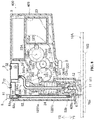
- Figs. 1 and 2 are longitudinal sectional views showing a stain removing device 100 according to the first embodiment of the present disclosure.
- the stain removing device 100 of the present disclosure shown in Fig. 1 and Fig. 2 is a handheld apparatus capable of partially cleaning clothing 10A that is served as a stain removing object, including a head part 1, a vibration unit 2, a liquid containing part 3, a water supply path 4, a battery 5, a waterproof cover part 6 and a housing body 9 in which a half of structures of these elements are arranged.
- the head part (the head part of a cylinder) 1 includes a knocking part 11 I forming a knocking surface 111 and a cylinder insertion portion 12 extending from the knocking part 11.
- a longitudinal section of the knocking part 11 is substantially semicircular shape and is more particularly slightly closer to the circle shape than the semicircular shape.
- the head part 1 is made of a resin such as nylon, and vibrates in a direction substantially orthogonal with the knocking surface 111 in a state in which the head part 1 protrudes into a head accommodation part 92 recessed in the housing body 9 from the housing body 9 via an opening 91, and exerts a knocking force to the clothing 10A that is served as the stain removing object disposed opposed to the knocking surface 111.
- the direction substantially orthogonal with the knocking surface 111 is referred to as a vibration direction.
- a direction in which the head part 1 faces the clothing 10A is referred to as a protruding direction Y1
- the opposite direction is referred to as a returning direction Y2.
- the material of the head part 1 is not limited to resin, and may also be metal (for example, Stainless Used steel, sus) and the like.
- the vibration unit 2 includes a motor 23 rotating by using power supplied from a battery 5 that is served as a power supply part; first to third gears 22A to 22C for transmitting the rotation force of the motor 23; a cylinder 21 for supporting the head part 1 by making the knocking surface 111 at a front end and moving in the vibration direction; and a coil spring 24 served as an elastic member accommodated inside the cylinder 21.
- the first gear 22A has a large-diameter portion 122a engaged with a drive gear 123 of the motor 23 and being rotatable around a shaft 122ab and a small-diameter portion 122b integrally formed and coaxially arranged with the large-diameter portion 122a.
- the second gear 22B is disposed between the first gear 22A and the third gear 22C, and has a large-diameter portion 122c engaged with the small-diameter portion 122b of the first gear 22A and being rotatable around a shaft 122cd, and a small-diameter portion 122d integrally formed and coaxially arranged with the large-diameter portion 122c and engaged with the third gear 22C.
- the third gear 22C is configured to rotate in a clockwise direction around a shaft 122ee (see Fig. 1 ), and have four protrusions 22c spaced equally in the circumferential direction and parallel to the shaft 122ee at its edge.
- the number of the protrusions 22c is not limited to four, and may be one to three, or five or more.
- the cylinder 21 includes a coil spring accommodation portion 121a having a tubular shape with a bottom and receiving therein the coil spring 24 which is in a extending/contracting state in the vibration direction, an inserted portion 121c inserted into the cylinder insertion portion 12 of the head part 1; and a liquid storage portion 121b disposed between the inserted portion 121c and the coil spring accommodation portion 121a and capable of storing liquid therein.
- a fixing portion 93 of the coil spring accommodation portion 121a extending in a boss shape from the housing body 9 toward the protruding direction Y1 is inserted through an opening 1121a, and accommodates the other side of the coil spring 24 supported at a base end of the fixing portion 93.
- the coil spring accommodation portion 121a includes an engaging claw 1121b which can engage with the protrusion 22c of the third gear 22C at its side surface. When the protrusion 22c is not engaged with the engaging claw 1121b (see Fig.
- the cylinder 21 exerts an elastic force via the coil spring 24 toward the protruding direction Y1 on a bottom surface 1121c of the coil spring accommodation portion 121 a that abuts the other side of the coil spring 24, thus the head part 1 is pushed out.
- the cylinder 21 exerts a compressive force via the bottom surface 1121c to the coil spring 24 along with the rotation of the third gear 22C, so that the head part 1 moves toward the returning direction Y2. Thereafter, when the protrusion 22c is disengaged from the engaging claw 1121b, the head part 1 moves toward the protruding direction Y1 due to the elasticity of the compressed coil spring 24. By repeating such operations, the head part 1 vibrates (amplitude movement).
- the third gear 22C has four protrusions 22c, and the head part 1 reciprocates four times by means of making one rotation of the third gear 22C.
- the liquid storage portion 121b is composed of a wide portion 1121d whose width is wider than the width of opening 91 of the housing body 9 and a narrow portion 1121c e whose width is narrower than the width of the opening 91 of the housing body 9 and which is projecting from the opening 91.
- the wide portion 1121d is fixed at the edge of the opening 91 so as to restrict the moving range of the cylinder 21 in the protruding direction Y1.
- the wide portion 1121d of the liquid storage portion 121b is connected with a liquid supply pipe 41 that will be described below, thus the liquid storage portion 121b stores the liquid supplied from the accommodation part through the liquid supply pipe 41, and supplies the liquid to the inserted portion 121c via the narrow portion 1121 e.
- the inserted portion 121c has a water supply hole 1121f extending from the narrow portion 1121c and an inserted segment 1121g (see Fig. 2 ) which is inserted into the hole of the cylinder insertion portion 12 of the head part 1 by slightly pressing.
- a water supply groove (slit groove) 12a extending in an axial direction is formed intermittently on the outer periphery of the cylinder insertion portion 12. The liquid in the narrow portion 1121e is supplied to the inserted segment 1121 g via the water supply hole 1121f, in a state where the head part 1 vibrates due to the vibration of the vibration unit 2, as shown in Fig.
- the liquid is discharged little by little (1 to 1.5 cc/min) from a discharge port 1121h of the water supply groove 12a at a predetermined depth (about 0.1 to 0.3 mm in this embodiment) located in the gap between the cylinder insertion portion 12 and the inserted segment 1121g.
- the head part 1 when the head part 1 does not vibrate, the liquid cannot be discharged from the discharge port 1121h due to surface tension but remains between the cylinder insertion portion 12 and the inserted portion 121c.
- the size of the water supply groove 12a is adjusted to such a degree that a small amount of liquid is discharged by virtue of vibration of the head part 1, and the amount of the used liquid is smaller than that of other cleaning methods such as spray cleaning and brush cleaning, therefore, the liquid is difficult to scatter to any position other than the stain portion 10a of the clothing 10A.
- the cylinder inserting portion 12 is not limited to being inserted into the inserted portion 121c by pressing, and may be inserted by screw fixing.
- the head part 1 can be removed from the inserted portion 121c, and another head part can be mounted to the inserted portion 121c. Therefore, in the stain removing device 100, for example, when dirt is adhered to the knocking surface 111 which directly abuts the stain portion of the clothing 10A, the head part 1 may be removed and cleaned, or be replaced with a new one.
- the water supply groove 12a may be formed in the inserted segment 1121 g instead of the cylinder insertion portion 12.
- the present disclosure is not limited to the configuration in which the surface tension acts on the liquid at the discharge port 1121h, the present disclosure may adopt another configuration, in which the liquid is prevented from dropping due to the surface tension at the opening end of the water supply hole 1121f when the head part 1 does not vibrate, by means of adjusting the water supply hole 1121f of the cylinder 21 to a predetermined diameter (for example, 0.3 mm).
- the liquid containing part 3 includes an accommodation part body 31 for containing the liquid discharged from the inserted portion 121c and supplied to the periphery of the head part 1 and a cover member 33 clogging the liquid supply hole 32 formed in the accommodation part body 31.
- An air hole (not shown) is formed in the cover member 33. Therefore, even if the liquid supply hole 32 is clogged by the cover member 33, the inside of the liquid containing part 3 does not become negative pressure, the liquid can drop from the discharge port 1121h immediately after the start of vibration since the liquid can successfully flow into the water supply path 4.
- the liquid only can be water, a detergent mixed solution in which water and a detergent are mixed at a constant ratio, or a detergent exclusive for stain removing and the like.
- the detergent mixed liquid is used.
- the detergent mixture is continuously supplied to the clothing 10A, so that the detergent does not disappear from the stain portion 10a due to vaporization, scattering or the like during the stain removing operation, thereby maintaining a high stain removing effect.
- there is no need to additionally provide a unit for supplying the detergent so the structure of the apparatus is simpler.
- the water supply path 4 supplies the liquid in the liquid containing part 3 to the periphery of the head part 1.
- the water supply path includes a flexible liquid supply tube 41, the liquid storage portion 121b, the water supply hole 1121f and the inserted segment 1121g of the inserted portion 121c, and the water supply groove 12a of the head part 1, in which one end 41a of the flexible liquid supply tube 41 is connected to the liquid containing part 3, the other end 41b is connected to the wide portion 1121d of the liquid storage portion 121b.
- one end of the water supply path 4 is constituted by one end 41a of the liquid supply tube 41, and the other end is constituted by the discharge port 1121h located at the opening end of the water supply groove 12a between the inserted segment 1121g and the cylinder insertion portion 12
- an absorption pad 10B abuts the bottom of the stain portion 10a of the clothing 10A, and the absorption pad 10B is used when the housing body 9 is grasped in such a manner that the knocking face 111 of the head part 1 is configured to opposite to the stain portion 10a.
- the motor 23 When a power switch S provided on the outside of the housing body 9 is operated, the motor 23 is rotated when the power is supplied from the battery 5, and the rotation is decelerated and transmitted simultaneously to the third gear 22C by the first gear 22A and the second gear 22B.
- the protrusion 22c When the protrusion 22c is engaged with the engaging claw 1121b, the cylinder 21 and the head part 1 are lifted up by a predetermined dimension ⁇ (about 5 mm in the present embodiment) (see Fig. 1 ).
- the protrusion 22c is disengaged from the engaging claw 1121b, the cylinder 21 is pushed out due to the elasticity of the coil spring 24, so that the head part 1 knocks the stain portion 10a (see Fig. 2 ).
- the liquid supply tube 41 absorbs the vibration of the cylinder 21 by the flexible deformation of a central portion 41c, the liquid drops gradually from the discharge port 1121h along with the vibration and is transmitted to the side surface of the knocking part 11 and then is supplied to the stain portion 10a.
- the stain removing device 100 of the present embodiment removes the stain by transferring the stain of the clothing 10A and the liquid together to the absorption pad 10B.
- the absorption pad 10B various components which has a high liquid absorption rate may be used as the absorption pad 10B.
- a kitchen paper can be used as the absorption pad 10B after being folded.
- the dropped liquid is stably absorbed by the absorption pad 10B, so the high stain removing efficiency can be maintained.
- the detergent mixed solution in the liquid state since the detergent mixed solution in the liquid state is used, the detergent can be easily and continually supplied to the stain portion 10a, even if the contact position of the head part 1 is changed.
- the vibration unit 2 causes the head part 1 to vibrate when the power is supplied, since the operation of knocking the clothing 10A by the head part 1 can be automated, the knocking force becomes uniform and the hands are not needed to move quickly, thus the hand cannot fatigue even if the stain removing operation is performed for a long time.
- the discharge port 1121h of its other end is opened at the periphery of the head part 1 rather than the knocking surface 111 of the head part 1, and the liquid is supplied to the periphery of the head part 1, so the water supply path 4 will not be clogged even if the solid stain constituting the stain portion 10a is attached to the knocking surface 111, thereby stably maintaining the stain removing effect.
- the cross section of the flow path of the water supply path 4 an appropriate amount of liquid is continuously supplied toward the stain removing object along with the vibration, so the stain removing effect can be enhanced.
- the structure that the liquid drops by means of vibration is used, the structure is simpler than, for example, other structures that the liquid is sent by a pump.
- the stain removing device 100 according to the present embodiment as described above is compact and has good portability, and when the spill of eating or cosmetics etc. adheres to the fabric, it can be washed immediately so that the stain is inconspicuous.
- curtains, mats, etc. which are not easy to be washed integrally, can be partially washed suitably.
- the waterproof cover part 6 is detachably attached to the housing body 9 via a rib 9a at a position of the side surface of the knocking part 11, encircling the head part 1.
- the waterproof cover part 6 is made of an acrylic, and is a non-flexible and cylindrical transparent member.
- the vibration unit 2 causes the head part 1 to protrude by the elastic force of the coil spring 24.
- the stroke of the head part 1 By adjusting the stroke of the head part 1, the action end of the head part 1 is arranged to a position which slightly protrudes beyond the protruding end 61 of the waterproof cover part 6.
- a distance t in the vibration direction from the knocking surface 111 of the head part 1 at the protruding position to the protruding end 61 of the waterproof cover part 6 is set to a predetermined distance (about 1 to 2 mm in this embodiment).
- the stain removing operation is performed in such a state that the protruding end 61 of the waterproof cover part 6 presses against the clothing 10A, since the waterproof cover part 6 prevents the liquid scattering due to the vibration of the head part 1 and thus prevents the liquid from spreading over a wide range, the wetting area of the clothing 10A is reduced and the clothing 10A can be put on immediately after the stain removing operation.
- a distance between the body of the device and the clothing 10A can be always kept constant, and the force (knocking force) exerted by the head part 1 to the clothing 10A can be made appropriate and uniform.
- the action end of the head part 1 is arranged to the position that slightly protrudes beyond the protruding end 61 of the waterproof cover part 6, and an operation simulating an action of knocking (pressing) the stain portion 10a with hands can be automatically realized, since the head part 1 can clamp the clothing 10A when protruding due to the elasticity of the coil spring 24.
- the waterproof cover part 6 is transparent, the removing state of the stain portion can be confirmed during the stain removing operation through the waterproof cover part 6.
- the shape of the waterproof cover part 6 is not limited to a cylindrical shape, other shapes may also be used, for example, a substantially conical shape (a shape in which the protruding end 61 expands toward the clothing 10A), as long as it can cover the entire side surface of the knocking part 11. Further, the waterproof cover part 6 may be fixed to the housing body 9 other than being detachable.
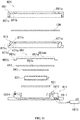
- Fig. 3 is longitudinal sectional view showing the stain removing device 100 when not in use.
- Fig. 3(A) is a longitudinal sectional view showing a head part 1X for preventing the liquid from dropping.
- Fig. 3(B) is a longitudinal sectional view showing a cap body (6X) for preventing the liquid from leaking.
- the head part 1X for preventing the liquid from dropping as shown in Fig. 3(A) may be mounted at the inserted portion 121c from which the head part 1 is pulled out.
- the head part 1X for preventing the liquid from dropping has an insertion part 12X designed to have a shape and size that allows to be inserted without forming a gap such as the water supply groove 12a (see Fig.
- the head part 1X for preventing the liquid from dropping at the time of carrying the stain removing device 100, it can prevent the liquid from leaking from the main body of the device due to shaking or vibration, and the head part 1X can be carried comfortably.
- the cap body 6X for preventing liquid from leaking shown in Fig. 3 (B) can be mounted to the housing body 9 from which the waterproof cover part 6 is detached.
- the cap body 6X for preventing the liquid from leaking is composed of a tubular portion 6Xa with one end 6Xa1 engaged with the rib 9a of the housing body 9 and a bottom portion 6Xb located at two side of the other end 6Xa2 of the tubular portion 6Xa.
- the liquid dropped from the discharge port 1121h is stored in a space Sp enclosed by the tubular portion 6Xa and the bottom portion 6Xb.
- the housing body 9 can be a structure in which the cap body 6X for preventing liquid leakage is mounted while keeping the waterproof cover part 6 in mounting state.
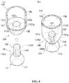
- FIG. 4 is a perspective view showing a part of the cylinder 155 and the head part 151 constituting the stain removing device according to the second embodiment of the present disclosure.
- Fig. 4(A) shows a state before the head part 151 is inserted into the cylinder 155.
- Fig. 4(B) shows a state in which the head part 151 is inserted in the cylinder 155.
- the stain removing device according to the present embodiment is different from the first embodiment in that a liquid amount adjustment part 159, which is capable of adjusting the liquid dropping amount.
- the configuration is substantially the same as that of the first embodiment, other than the configuration to be described below, so the description will be omitted.
- the liquid amount adjustment part 159 shown in Fig. 4 is composed of the cylinder 155 and the head part 151.
- the cylinder 155 adjoins the inserted segment 1121g of the inserted part 158 and a liquid storage portion 156 through a partition portion 157, and has first to third supply regions 157a to 157c formed at equal intervals on the edge portion of the partition portion 157.
- the supply holes 157x, penetrating the partition portion 157, of these supply regions 157a to 157c are formed in different quantity.
- one supply hole 157x is formed at the first supply region 157a
- three supply holes 157x are formed at the second supply region 157b
- five supply hole 157x are formed at the third supply region 157c.
- the number of the supply holes 157x is not limited to this.
- the head part 151 is provided with a notch 1152 at an end of an insertion portion 152, and has a plurality of water supply grooves 1153 extending from the notch 1152 to the knocking portion 11 on the side portion of the insertion portion 152.
- Fig. 5 is a diagram schematically showing the head part 151 shown in Fig. 4(B) together with the supply hole 157x.
- the notch 1152 is indicated by hatching.
- the notch 1152 is formed in the insertion portion 152 over a range corresponding to one supply region 157a (157b, 157c).
- the liquid in the liquid storage portion 156 shown in Fig. 4 flows into the notch 1152 from the supply holes 157x formed in any one of the supply regions 157a (157b, 157c) opposing to the notch 1152, and drops to the periphery of the knocking part 11 through the water supply grooves 1153.
- the dropping amount of the liquid varies according to the supply region 157a (157b, 157c) opposed to the notch 1152.
- the dropping amount of the liquid is increased in the order of the state shown below: a state shown in Fig. 5(A) in which the notch 1152 is opposed to the first supply region 157a, a state shown in Fig. 5(B) in which the notch 1152 is opposed to the second supply region 157b, and a state shown in Fig. 5(C) in which the notch 1152 is opposed to the third supply region 157c.
- the stain removing device causes the liquid to drop from the gap between the water supply groove 1153 served as the other end of the water supply path 158 and the insertion portion 152 of the head part 151 through using the vibration caused by the vibration unit 2, and has the liquid amount adjustment part 159 shown in Fig. 4 which can adjust the dropping amount of the liquid.
- the liquid drops too much, the result is that circle blurring may be caused.
- the liquid does not drop to the clothing 10A in excess or insufficiency by means of utilizing the liquid amount adjustment part 159. Therefore, it can prevent the stain removing effect from being decreased due to insufficiency supply of the liquid, and prevent circle blurring caused by a large amount of liquid being supplied to the stain portion 10a at once.
- the liquid amount adjustment part 159 is not limited to the configuration described above as long as the liquid dropping amount can be adjusted. Furthermore, the configuration of the liquid amount adjustment part 159 may be applied to the stain removing devices of the third to fifth and the seventh embodiments described later. Furthermore, in the present embodiment, the water supply groove 1153 is formed on the insertion portion 152, but it may also be formed on the inserted portion 158.
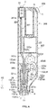
- Fig. 6 is a longitudinal sectional view showing a stain removing device 300 according to a third embodiment of the present disclosure.
- the shape of the housing body 309 of the stain removing device 300 of the present embodiment is substantially rectangular. A part of the arrangement positions and configuration of the elements in the housing body 309 is different from that of the first embodiment. Additionally, comparing to the first embodiment in which the housing body 9 is used while keeping it in a substantially horizontal position, the housing body 9 of the present embodiment is used while keeping it in a substantially standing attitude.
- the configuration is substantially the same as that of the first embodiment, other than the configuration to be described below, so the same reference numerals are given and the description thereof will be omitted.
- a cylinder 321, a third gear 322C, a second gear 322B, a first gear 322A and a motor 23 forming a vibration unit 302 are disposed in the housing body 309 in this order along the vibration direction.
- the cylinder 321 is composed of a coil spring accommodation portion 321a, an inserted portion 321c, and a hollow connecting portion 321b that connects the coil spring accommodation portion 321a and the inserted portion 321c.
- the structure of the coil spring accommodation portion 321a is same as that of the coil spring accommodation portion 121a (see Figs.
- the structure of the inserted portion 321c is the same as that of the inserted portion 121c (see Figs. 1 and 2 ) of the first embodiment except that the inserted portion 321c has a hollow connection end 1321b extending from the water supply hole 1121f to the inside of the connecting portion 321b. Further, a through hole 393a throughout the vibration direction is formed on a fixing portion 393 of the housing body 309 inserted into the coil spring housing portion 321a.
- the water supply path 304 is composed of a liquid supply hose 341, the connection end 1321b of the inserted portion 321c, the water supply hole 1121f, the inserted segment 1121g and the water supply groove 12a provided at the cylinder insertion portion 12 of the head part 1.
- One end 341 a of the liquid supply hose 341 is connected to the liquid containing part 3 and pass through the through hole 393a of the fixing portion 393, an axial center portion of the coil spring 24 and the coil spring accommodation portion 321a, and the other end 341b is connected to the connection end 1321b inside the connection portion 321b via the opening 1321ab.
- the liquid supply hose 341 has a deformation portion 341c which is connected between the liquid containing part 3 and the connection end 1321b with a enough length and is flexibly deformed (absorbs vibration) along with the vibration of the vibration unit 302.
- the liquid supply hose 341 may be connected between the liquid containing part 3 and the connection end 1321b without a enough length.
- a part of the liquid supply hose 341 is preferably snake belly shape.
- the stain removing device 300 since the motor 23 is rotated by power supply from the battery 5 by means of operating the power switch S outside the housing body 309, the cylinder 321 and the head part 1 can vibrate and the liquid can drop from the discharge port 1121 h by utilizing the rotation of the third gear 22C and the elasticity of the coil spring 24, the stain removing device 300 has same effect as the stain removing device 100 of the first embodiment.
- Figs. 7 and 8 are longitudinal sectional views showing a stain removing device 400 according to a fourth embodiment of the present disclosure.
- the stain removing device 400 of this embodiment is different from the first embodiment in that it includes a detergent containing part 7 and a detergent supply unit 8.
- a detergent containing part 7 includes a detergent containing part 7 and a detergent supply unit 8.
- other configurations are the same as that in the first embodiment, so the same reference numerals are given, and the explanation is omitted.
- the detergent containing part 7 includes an accommodation body 71 for containing a liquid detergent supplied to the periphery of the head part 1, and a cover member 73 provided with an air hole (not shown) and closing a liquid supply hole 72 formed on the accommodation body 71.
- the detergent supply unit 8 supplies the detergent in the detergent containing part 7 to the periphery of the head part 1, and is composed of a detergent dropping button 81, a detergent supply hose 82, and a detergent supply portion 409a formed on the housing body 409 and opening to the periphery of the head part 1.
- One end 82a of the detergent supply hose 82 is connected to the detergent containing part 7 at a position where the pressure force is applied by the detergent dropping button 81, and the other end 82b is connected to the detergent supply portion 409a.
- the detergent supply portion 409a has a shape that the liquid is supplied from the knocking part 11 facing the head part 1 to a direction inclined slightly downward with respect to the horizontal, and the opening end is in a nozzle shape.
- the detergent dropping button 81 is elastically in contact with a coil spring 81a for exerting an elastic force from the pressed position to the pushing up position.
- the stain removing device 400 can adjust the detergent amount according to the degree of stain of the stain portion 10a.
- the stain can be removed by using detergent supplied by the detergent supply unit 8, and the clothing 10A can be rinsed by only using the water supplied from the water supply path 4.
- the structure for supplying detergent by using the detergent dropping button 81 is not limited to the above, and it may also be a structure that will be supplied by vibration is similar to the liquid in the liquid containing part 3, for example.
- the device body is prevented from being enlarged by disposing the detergent containing part 7 and the detergent supply unit 8, therefore, the constitution of the third embodiment can be applied to the water supply path 304, the cylinder 321 and the fixing portion 393 of the housing body 409.
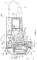
- Fig. 9 is a longitudinal sectional view showing a stain removing device 500 according to a fifth embodiment of the present disclosure.
- the stain removing device 500 according to the present embodiment is different from the first embodiment in that it includes a vapor ejection unit 508 capable of ejecting vapor toward the knocking part 11 of the head part 1 and the motor 23 is driven by being supplied power via a power cable C with a mandrel C1.
- the stain removing device 500 is powered by the power cable C, as a result, there is no need to be imbedded a battery inside of the housing body 509, and thus the device body is further miniaturized.
- the power cable C is not limited to the one having the mandrel C1, and may also be a USB cable having a USB connector.
- the above first to fourth embodiments may be structures in which the power is supplied by the power cable C, but the present embodiment may also be a structure that the power is supplied by the battery.
- other than the configuration to be described later other configurations are the same as that in the first embodiment, so the same reference numerals are given, and the explanation is omitted.
- the vapor ejection unit 508 includes a liquid accommodation portion for vapor 507, a liquid dropping button for vapor 581, a vapor generation portion 583 for generating vapor, a liquid supply pipe for vapor 582 for supplying the water in the liquid accommodation portion for vapor 507 to the vapor generation portion 583, and a vapor ejection portion 584, in where one end 584a of the vapor ejection portion 584 is connected to the vapor generation portion 583 and the other end 584b is opened at the periphery of the head part 1.
- the liquid dropping button for vapor 581 is elastically in contact with a coil spring 581a for exerting an elastic force from the pressed position to the pushing up position.
- the liquid accommodation portion for vapor 507 includes a liquid accommodation body for vapor 571 for containing water for vapor, and a cover member 573 for blocking a liquid supply hole for vapor 572 formed on the liquid accommodation body for vapor 571 and having an air hole (not shown) formed therein.
- the vapor generation portion 583 is composed of a heater switch 586 capable of switching to a power state of a heater 585, the heater 585 that generates heat while being powered via the power cable C, a vapor generation body 583 in which the heater 585 is disposed, and a thermostat 587 provided on the side wall of the vapor generation body 583 and adjusting the power state of the heater 585 according to the temperature of the heater 585.
- the thermostat 587 is configured to stop supplying power to the heater 585 so as to cool the heater 585 when an upper limit temperature is reached, and to supply power to the heater 585 again when a lower limit temperature is reached.
- the heater is powered by means of the operation of the heater switch 586 to generate heat.
- the liquid dropping button for vapor 581 is pushed at an appropriate timing and then the liquid drops from the liquid accommodation portion for vapor 507 to the heater 585, vapor is generated and ejected to the head part 1 from the other end of the vapor ejection portion 584. Since the stain removing device 500 includes the vapor ejection unit 508 for ejecting the vapor toward the head part 1, it can warm the clothing 10A by the vapor and perform the stain removing operation, thereby improving the stain removing effect.
- the vapor has higher kinetic energy than water in the liquid state including hot water, and the vapor is easier soaked into the solid stain and the clothing 10A than the water in the liquid state, the solid stain and the dirt deep inside of clothing fibers can be dissolved and removed by the vapor, which also contributes to the improvement of the stain removing effect. Furthermore, discoloration of the clothing 10A can be prevented, since it is unnecessary to use a strong bleaching agent for stain removing.
- the structure of the fifth embodiment can be applied to the cylinder 321 and the fixing portion 393 of the housing body 509, since the maximization in the size of the device body is suppressed by providing the vapor ejection unit 508.
- Fig. 10 is a longitudinal sectional view showing a stain removing unit 600 according to a sixth embodiment of the present disclosure.
- Fig. 11 is an exploded view showing a heating apparatus 601 constituting the stain removing unit 600 shown in Fig. 10 .
- the stain removing unit 600 of the present embodiment shown in Fig. 10 is composed of the stain removing device 100 of the first embodiment and the heating apparatus 601.
- the heating apparatus 601 includes an absorption pad combined member (cover for absorption pad combined member) 681, a main cover 671, a decorative plate 661, a heating plate 651, a first heat insulation material 641, a heater 631, a second heat insulation material 621, and an apparatus body 611.
- the absorption pad combined member 681 and the main cover 671 are circular in the plan view, and an opening 681a and an opening 671a are formed at the centers of the absorption pad combined member 681 and the main cover 671, respectively.
- the absorption pad combined member 681 rotates in a state in which a absorption pad 10B is sandwiched between one surface 681b of the absorption pad combined member 681 and one surface 671b of the main cover 671, and a thread portion 671c and a thread portion 681c are mounted on the main cover 671 by being mutually engaged with each other.
- the decorative plate 661 has a step between a central portion 661 a and an end portion 661b.
- a raised surface 661ab of the central portion 661a is exposed through the opening 671a and is substantially parallel to one surface 671b of the main cover 671, and the end portion 661b is sandwiched between the other end 671d of the main cover 671 and the apparatus body 611.
- the decorative plate 661 is made of, for example, stainless steel.
- Through holes 661c and 671e passing through a safety switch 1614 to be described later are respectively formed in the end portion 661b of decorative plate 661 and the main cover 671.
- the heating plate 651 is insertedly disposed in the central portion of the decorative plate 661.
- a knocked surface 651 a to which an external force is exerted from the head part 1 of the stain removing device 100, is opposite to the heating plate 651.
- the heating plate 651 is made of, for example, aluminum with high thermal conductivity.
- the thickness of the heating plate 651 is set to about 1 to 2 mm. Since the heating plate 651 has high strength and high thermal conductivity simultaneously, it can quickly and uniformly transmit the heat from the heater 631 to the absorption pad 10B, and the deformation of the absorption pad 10B is suppressed by the external force exerted by the head part 1 in the stain removing operation, thereby maintaining a high stain removing efficiency.
- the first heat insulation material 641 is a heat insulation material disposed at a back side of the heating plate 651 and configured for the temperature adjustment, and is made of, for example, silicon rubber.
- the second heat insulation material 621 is disposed on the apparatus body 611 and blocks the heat of the heater 631, and is made of, for example, glass wool.
- the heater 631 disposed between these heat insulation materials can use for example a ceramic heater.
- the heating plate 651 has a good appearance by performing coating, but it is also possible to adopt a configuration without using the decorative plate 661.
- the apparatus body 611 includes a power cable 1613, a main switch 1611 capable of switching the power state to the heater 631, a thermostat 1612 capable of adjusting the power state of the heater 631 according to the temperature of the heater 631, and the safety switch 1614.
- an upper limit temperature for example, 70°C
- the thermostat 1612 stops the power supply to the heater 631 to cool the heater 631.
- the lower limit temperature for example, 60°C
- the safety switch 1614 is configured to protrude from the one surface 671b of the main cover 671 via the through holes 661c and 671e, and the power can be supplied to the heater 631 when the absorption pad 10B mounted at a predetermined position is pressed. On the other hand, the power supplied to the heater 631 can be stopped when the absorption pad 10B is not pressed. That is, the heating apparatus 601 can be configured to mount the absorption pad 10B to the predetermined position on the main cover 671 and make the absorption pad combined member 681 to be used in the case of closure.
- the stain removing unit 600 of the present embodiment continuously heats the stain portion 10a at about 50°C, since the dirt is more easily dissolved in the liquid at this time, the stain removing operation can be perform, as a result, the stain removing effect is further improved.
- the stain removing effect is further improved.
- it is not necessary to use a strong bleaching agent in order to remove stain the color fading of the clothing 10A is prevented.
- the heating apparatus 601 is used in combination with the stain removing device 100 of the first embodiment, but it is also possible to use in combination with the stain removing devices 200 to 500 of the second to fifth embodiments described above or in combination with the stain removing device 700 of the seventh embodiment described below.
- the heating apparatus 601 has a circular plane, but may have a rectangular plane.
- one side of the absorption pad combined member is connected to another component of the heating apparatus (the main cover, the decorative plate, the heating plate, the first heat insulation material, the heater, the second heat insulation material, the apparatus body) via a hinge or the like.
- a foldable structure is constructed in which the absorption pad combined member is sandwiched between other components of the heating device 60.
- Fig. 12 is a view showing a stain removing device 700 according to a seventh embodiment of the present disclosure.
- Fig. 12(A) is a longitudinal sectional view showing the stain removing device 700 of this embodiment
- Fig. 12(B) is a perspective view of a waterproof cover part of the stain removing device 700 of this embodiment.
- Fig. 12(C) is a longitudinal sectional view showing the waterproof cover part in an exploded manner.
- Fig. 13 is a schematic circuit diagram showing a circuit for supplying power to the motor 23 and the heater 731 of the stain removing device 700, and shows three power states corresponding to sliding positions of an operation portion SS1 of a switch SS. Further, in the circuit of Fig. 13 , a power up part is represented by solid lines and a non-power up part portion is represented by dot-chain lines.
- the stain removing device 700 of the present embodiment is different from the third embodiment shown in Fig. 6 mainly in that the structure of the waterproof cover part 706 and the motor 23 is driven while being powered by a USB connector CC1.
- the USB connector CC 1 is connected to an external power source BB (see Fig. 13 ) via a USB cable CC2 (see Fig. 13 ). Therefore, since the stain removing device 700 of the present embodiment is configured to be powered by the external power source BB, it is not necessary to insert the battery within the housing body 709, and thus the device body becomes more compact.
- the waterproof cover part 706 includes a guide frame 732, a heater 731, a pressing member 733, a heat insulation packing 734, and a power connector 735.
- the waterproof cover part 706 of the present embodiment is also detachable with respect to the housing body 709 through a rib 709a at a position on a side surface of the knocking portion 11 which encircles the head part 1.
- the guide frame 732 has a bottom surface region 732c with flat annular shape, an inner cylinder region 732a extending from an inner periphery of the bottom surface region 732c, and an outer cylinder region 732a which is coaxial with the inner cylinder region 732a and extends from an outer periphery of the bottom surface region 732c.
- An internal space Is is formed by these regions 732a-732c. Therefore, as shown in Fig. 12(C) , an inner surface of the bottom surface region 732c is curved based on the shape of the heater 731.
- the length L1 of the inner cylinder region 732a in the extending direction is shorter than the length L2 of the outer cylinder region 732b in the extending direction.
- the heater 731, the pressing member 733 and the heat insulation packing 734 are disposed in this order from the bottom surface region 732c toward an opening 732d.
- an outer surface 732e of the bottom surface region 732c is pressed by the clothing 10A.
- the guide frame 732 is made of, for example, aluminum having high thermal conductivity. Therefore, the heat from the heater 731 can be quickly transferred to the clothing 10A, and the temperature of the heater 731 can be rapidly decreases after use, so the stain removing device 700 can be stored and carried immediately after use.
- the heater 731 is an annular member constituted by wound nickel-chromium heating wires, and generates heat while being powered through the USB connector CC 1 and the power connector 735.
- the power supplied to the heater 731 is, for example, about 5W.
- the temperature of the heater 731 is set to be about 80 °C -100 °C when generating heat.
- the heater 731 may be another heater such as a ceramic heater.
- the pressing member 733 is an annular member having a pressing surface 733a which is curved based on the shape of the heater 731 having a circular cross section. Such pressing member 733 restricts the movement of the heater 731 by causing the pressing surface 733a and the heater 731 to abut against each other in the internal space Is, and inhibits the heat of the heater 731 from transmitting to the rib 709a.
- the heat insulation packing 734 is an annular member made of silicon and mounted along the outer cylinder region 732b, and there is a gap between the heat insulation packing 734 and the inner cylinder region 732a of the guide frame 732 in the inner space Is.
- the heat insulation packing 734 is composed of a cylinder region 734a abutting against the outer cylinder region 732b and the pressing member 733, and a flange region 734b extending outward from an end portion of the cylinder region 734a.
- the power connector 735 shown in Fig. 12(B) and Fig. 13 is a member which protrudes from the internal space Is and is attached to the opening end surface of the guide frame 732, and is engaged with a housing body side connector (not shown) provided on a side of the housing body 709.
- the heater 731 is electrically connected to the external power source BB via the power connector 735.
- the waterproof cover part 706 as described above is mounted to the housing body 709 by inserting the rib 709a into the internal space Is to be in contact with the inner peripheral surface 734c of the heat insulation packing 734. At this time, an end surface of the outer cylinder region 732b of the guide frame 732 is brought into contact with the housing body 709 via the flange region 734b of the heat insulation packing 734, as a result, the waterproof cover part 706 is positioned in the vibration direction, and the flange region 734b serves to separate the housing body 709 from the outer cylinder region 732b.
- the length L3 of the rib 709a in the vibration direction is configured to be shorter than the length L4 of the heat insulation packing 734 in the vibration direction, and a front end of the rib 709a is a position separated from the pressing member 733.
- the heat insulation packing 734 is located between the outer cylinder region 732b of the guide frame 732 and the rib 709a, and a heat insulation space Gp (see Fig. 12(A) ) is formed between the inner cylinder region 732a of the guide frame 732 and the rib 709a.
- the flange region 734b separates the housing body 709 from the outer cylinder region 732b of the guide frame 732, the front end of the inner cylinder region 732a is the position separated from the housing body 709.
- the pressing member 733 and the guide frame 732 which become of high temperature due to the heat from the heater 731, are configured to not in direct contact with the housing body 709 including the rib 709a, so a damage to the body of the stain removing device 700 caused by the heat from the waterproof cover part 706 is suppressed.
- the waterproof cover part 706 is provided with a temperature adjustment portion such as a thermostat capable of adjusting the power state to the heater 731 according to the temperature of the heater 731 in order to prevent overheating of the guide frame 732 and even the clothing 10A. Further, the waterproof cover part 706 may be provided with a temperature display portion such as a thermo tape for displaying the temperature of the guide frame 732. As a result, the user can hold the temperature of the waterproof cover part 706.
- a temperature adjustment portion such as a thermostat capable of adjusting the power state to the heater 731 according to the temperature of the heater 731 in order to prevent overheating of the guide frame 732 and even the clothing 10A.
- the waterproof cover part 706 may be provided with a temperature display portion such as a thermo tape for displaying the temperature of the guide frame 732. As a result, the user can hold the temperature of the waterproof cover part 706.
- the vibration unit 702, the liquid containing part 703, and the water supply path 704 are functionally the same as those of the stain removing device 300 of the third embodiment, but their shapes and arrangement positions in the housing body 709 are different from those of the stain removing device 300 of the third embodiment, as shown in Fig. 12(A) .
- a third gear 722C constituting the vibration unit 702 is provided with two protrusions 722c protruding in a radial direction and spaced equally in a circumferential direction, for substituting the protrusion 22c (see Fig. 6 ) extending parallel to the axis 122ee.
- the number of vibrations per unit time of the head part 1 can be adjusted by the number of the protrusions 722c.
- the knocking action of the head part 1 is set to be performed 15 to 20 times per second.
- the number of the protrusions 722c is not limited to two, and may be one or three or more.
- the cylinder 721 constituting the vibration unit is formed by a part of a second member 721y integrally engaged on an outer periphery of the first member 721x having a bottomed cylindrical shape in the vibration direction.
- a coil spring accommodation portion 721a is formed inside the first member 721x.
- the liquid storage portion 721b, the inserted portion 721c and the inserted segment 1121g are constituted by a second member 721y having a bottomed cylindrical shape and formed from a repeating portion of the first member 721x to the head part 1.
- the second member 721y covers the first member 721x to an approximate center in the vibration direction, and an engaging claw 1721b engaged with the protrusions 722c of the third gear 722C is arranged on an end portion of a side of the second member 721y closing the first member 721x.
- the other end of the coil spring 24 and the housing body 709 are composed of other members, and its base end side accommodates the fixing portion 793 fixed to the housing body 709.
- the liquid storage portion 721b is composed of a wide portion 1721d whose width is wider than the width of the opening 1721g of the housing body 709 and a narrow portion 1721e whose width is narrower than the width of the opening 1721 g of the housing body 709 and protruding from the opening 1721g.
- the wide portion 1721d is arranged on a restriction member 709b by an opening edge arranged along the housing body 709, so that the moving range of the cylinder 721 in the protruding direction Y1 is restricted.
- the whole or substantially the entirety of the housing body 709 has a double structure, and it is effective to dispose components such as the vibration unit 702 in such a housing body 709.
- a fixing member such as a screw fixed at an inner surface of the housing body are not visible from the outside of the housing body, and the appearance design of the stain removing device can be improved.
- the inserted portion 721c has a tapered water supply hole 1721f extending from the narrow portion 1721e and an inserted segment 1121g having the substantially same width as the narrow portion 1721e.
- the cylinder insertion portion 12 of the head part 1 is inserted into the inserted segment 1121 g by slightly pressing.
- a bottom surface 703a of the accommodation part body 703a of the liquid containing part 703 is inclined towards one end 741a of a liquid supply pipe 741.
- the shape of the liquid containing part 703 is different from that of the stain removing device 300 of the third embodiment.
- the other end 741b of the liquid supply pipe 741, the one end 741a of which is connected to the liquid containing part, is connected to the wide portion 1721d of the cylinder 721.
- a coil spring 741c is wound around the other end 741b of the liquid supply pipe 741 to prevent the flexibly deformed liquid supply pipe 741 from curving to make the liquid from not to flow.
- the switch SS is a slide type member, and the operation portion SS 1 of the switch SS is set to three slide positions: an OFF position as shown in Fig. 12(A) and Fig. 13(A) , a first slide position as shown in Fig. 13(B) , and a second slide position as shown in Fig. 13(C) .
- the operation section SS1 when the operation section SS1 is at the OFF position, it is a power off state in which the power is not supplied to neither the motor 23 of the vibration unit 702 nor the heater 731; when the operation section SS1 is at the first slide position, it is a preheating state in which only the heater 731 is powered via the power connector 735, and when the operation section SS1 is at the second slide position, it is a heating and knocking state in which both of the motor 23 of the vibration unit 702 and the heater 731 are powered simultaneously.
- the waterproof cover part 706 presses against the clothing 10A and the clothing 10A is heated.
- the stain removing operation can be performed after the clothing 10A has been heated.
- the stain removing device 700 of the present embodiment is of a structure in which the waterproof cover part 706 pressing the clothing 10A is heated by the heat from the heater 731 during the stain removing operation, the stain portion of the stain removing object and its periphery can always be heated via the waterproof cover part 706 during the stain removing operation even if the heating apparatus 601 shown in Fig. 10 is not separately used, thus the miniaturization is realized and the stain removing effect is further improved. Further, so long as the heater is disposed inside the head part rather than the waterproof cover part, the heat can be transmitted only to the clothing 10A intermittently, and the clothing 10A cannot be efficiently heated.
- a LED which is lit up when the heater 731 is in the powered state, may be provided on the stain removing device 700 of the present embodiment. By doing so, the user can also hold to heat the waterproof cover part 706.
- the waterproof cover part 706 of the present embodiment is detachable from the housing body 709.
- the waterproof cover part 6, in which the heater of the stain removing device 100 of the first embodiment shown in Fig. 1 is not provided, may be mounted on the housing body 709 of the stain removing device 700 according to the dirty degree of the clothing 10A or available power and the like.
- the switch SS is a slide type, but other types of switch such as a rotary type switch or a push button type switch may be used.
- the stain removing device700 of the present embodiment and the heating apparatus 601 shown in Fig. 10 may be used simultaneously. By doing so, the clothing 10A can be heated more effectively, and the stain removing effect can be further improved.
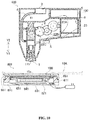
- Fig. 14 is a partial cross-sectional view showing a stain removing device 800 according to an eighth embodiment of the present disclosure.
- the stain removing device 800 of the present embodiment is different from that of the first embodiment in that the liquid flows through the inside of the head part 181 rather than flow from the side surface of the head portion 1 (see Fig. 1 and the like).
- the configuration other than the configuration to be described later is the same as that of the first embodiment, so the description of the same configuration as that of the first embodiment will be omitted.
- the cylinder 183 shown in Fig. 14 has a coil spring accommodation portion (not shown), an inserted portion 183a, a liquid storage portion 183b, and a cylinder water supply hole 183a1.
- the coil spring accommodation portion accommodates the coil spring 24 (see Fig. 1 and the like), and the inserted portion 183a is a member in which a cylinder inserting portion 181 a of the head part 181 which will be described later is removably inserted.
- the liquid storage portion 183b is located between the inserted portion 183a and the coil spring accommodation portion, and stores the liquid supplied from the liquid accommodation portion 3 (see Fig. 1 and the like) therein.
- the cylinder water supply hole 183a1 is formed to pass through the inserted portion 183a from the liquid storage portion 183b and is opened to a cone shaped toward a base end 184a1 of the head part 181.
- the head part 181 includes the cylinder insertion portion 181 a into which the inserted portion 183a can be removably inserted, a knocking portion 181b formed with a knocking surface 182, a head water supply hole 184' extending to the knocking surface 182 through the head part 181.
- the head water supply hole 184' is composed of a water storage portion 184A, which has a substantially rectangular longitudinal cross section, and is opposed to the cylinder water supply hole 183a1 and opened at the base end 184a1 of the head part 181, and passes through the cylinder inserting portion 181a; an expanding portion 184C having a trapezoidal longitudinal cross section and an opening end 184a2 expanding and opened toward the center of knocking surface 182, and a small-diameter portion 184B connecting the water storage portion 184A and the small-diameter portion 184B.
- the flow path cross section of the small-diameter portion 184B is smaller than that of the water storage portion 184A and that of the expanding portion 184C.
- the liquid in the small-diameter portion 184B is slightly discharged to the expanding portion 184C when the head part 181 is vibrated by vibration unit (not shown). On the other hand, the liquid is prevented from dropping by an action of surface tension when the head part 181 is not vibrated.
- the liquid storage portion 183b, the cylinder water supply hole 183a1, and the head water supply hole 184' together with the liquid supply pipe 41 (see Fig. 1 ) constitute a water supply path 184.
- the liquid in the liquid storage portion 183b drops to the head part 181 from the cylinder water supply hole 183a1, and then flows through the head water supply hole 184' to be supplied to the knocking surface 182.
- a plurality of annular protruding portions 181 a' separated from each other in the vibration direction are formed on the side surface of the cylinder inserting portion 181a of the head part 181.
- the protruding portions 181a' is stably fixed by pressing against an inner surface of the inserted portion 183a.
- the vibration unit (not shown) vibrates the head part 181 when being powered, the action of knocking the clothing 10A (see Fig. 1 ) by the head portion 181 can be automated, as a result, the knocking force becomes uniform, and there is no need to quickly move the hand, the hand will not feel fatigue even if the stain removing operation is performed for a long time.
- the solid stain of the stain portion 10a (referring to Fig.
- the water supply groove 12a formed on the side surface of the head part 1, as in the stain removing device 100 shown in Fig. 1 are not required. Since the protruding portions 181a can be formed on the side surface of the head part 181, the head part 181 can be stably mounted to the cylinder 183 even if it is extracted from the cylinder 183 repeatedly many times.
- the configurations of the head part 181 and the cylinder 183 of the present embodiment may be applied to the other embodiments described above.
- the knocking surface 111 of the head part 1 is used downward, it may also be a structure in which the knocking surface 111 is used transversely. In this case, a structure for example in which the liquid is pump is used.
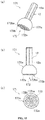
- FIG. 15 is a diagram showing a variant of the head part 1 shown in Fig. 1 .
- Fig. 15(A) is a perspective view showing the head part 171
- Fig. 15(B) is a side view showing the head part 171
- Fig. 15(C) is a bottom view showing the head part 171.
- a knocking surface 1 72 formed on the knocking portion 171 a of the head part 171 is composed of a base 172a and a surface 172ba of a plurality of protrusions 172b protruding from the base 172a.
- each of the protrusions 172b is hemispherical shape and regularly arranged in the base 172a.
- the stain removing devices 100 to 500 and 700 of the present disclosure are appropriately replaced with those having different shapes such as the head part 171 and the head part 1 according to the type of dirt constituting the stain portion 10 a, thereby removing stain more effectively.
- the head parts 1, 181 can be detached from the cylinders 21, 183 and replaced, but may also be an undetachable structure. Furthermore, the head part 1 may be configured to be rotatable about an axis parallel to the vibration direction by using a stroke motion.
- a mechanism for heating the liquid may be arranged in the stain removing devices 100 to 500 and 700, alternatively a structure in which the heated liquid drops toward the clothing 10A may also be arranged in the stain removing devices 100 to 500 and 700, therefore, the stain removing effect is further improved.
- the liquid containing part 3 is fixed in the housing body 9, but it may also be detachably mounted in the housing body 9.
- the liquid containing part 3 is provided at a position where the liquid can be supplied to the head part 1 without passing through the liquid supply pipe 41 and the cylinder 21, that is, the liquid containing part 3 is arranged at a position directly connected to the head part 1 or the periphery of the head part 1, the liquid containing part 3 and the head part 1 may be an integral structure which can be detached from the housing body 9.
- the stain removing operation is performed by mounting the liquid containing part 3 containing the liquid suitable for the state of the stain portion 10a to the housing body 9, thereby improving the stain removing effect.
- the blocking of the water supply path 4 caused by concentration of the water stain or calcium component at positions which are not easy to clean, such as inside of the liquid supply pipe 41 or the cylinder 21, can be prevented, thus it is not necessary to disassemble the body of the stain removing device 100 for cleaning.
- the liquid containing part 3 is transparent or semitransparent, a certain amount of the liquid can be drawn out from the housing body 9 during the stain removing operation.
- the liquid containing part 3 may be configured to include an accommodation body in which a liquid accommodation space is formed and a cover member for opening and closing the liquid accommodation space.
- the cover member can be taken down from the accommodation body when the liquid containing part 3 is taken down from the housing body 9, and since the liquid accommodation space can be replenished with the liquid, and the liquid in the liquid containing part 3 can be easily replaced with another kind of liquid such as ethanol, the convenience is improved and continuous use of the stain removing device 100 becomes possible.
- the replenishment and replacement and the like of the liquid can be performed when the liquid containing part 3 is detached from the housing body 9, so the housing body 9 will not be wetted when being replenished, and the housing body 9 is not required to be subjected to a waterproof treatment.
- the interior of the liquid containing part 3 can be cleaned by disassembling it into the accommodation body and the cover member, so the water stain and the calcium component can be easily removed.
- the head part 1 is configured to be removable from the liquid containing part 3. With such a configuration, the most appropriate head part 1 and the liquid may be selected and used according to the state of the stain portion 10a and the like, so the stain removing effect can be improved.
- the above configuration in which the liquid containing part 3 and the like can be detached from the housing body 9 may also be applied to the stain removing devices 300 to 500, 700, and 800 described above.
- the materials constituting the stain removing devices 100 to 500, 700, 800, and the heating apparatus 601 are not limited to those indicated by hatching in the respective drawings.
- the stain removing devices 100, 300, 500, 700, 800 in the case where only water as a liquid drops from the stain removing devices 100, 300, 500, 700, 800, it is effective to directly coat the detergent on the stain portion 10a of the clothing 10A in advance when the stain removing operation is performed.
- the stain removing devices 100, 300, 500, 700, and 800 perform the knocking action while supplying water so as to play the effect of removing stain, and also play the effect of rising by continuing the operation, since the dropped water transfers the stain and the detergent to the absorption pad 10B.
- the waterproof cover part 6 is cylindrical, but its cross-sectional diameter may be increased toward the protruding end 61 thereof. By doing so, the stain removing devices 100 to 500, 800 can be stably pressed against the clothing 10A.
Landscapes
- Engineering & Computer Science (AREA)
- Textile Engineering (AREA)
- Accessory Of Washing/Drying Machine, Commercial Washing/Drying Machine, Other Washing/Drying Machine (AREA)
- Cleaning By Liquid Or Steam (AREA)
Abstract
Description
- The present disclosure relates to a stain removing device and a stain removing unit, which can remove stains, such as cosmetics or foodstuffs attached to a fabric during consumption by means of knocking and cleaning, and make actions of knocking the stain portion of the fabric and supplying water to the stain portion to be automatically performed.
- In the case where a part of a fabric is adhered to stains, it is preferable to perform a cleaning treatment only on the stain portion of the fabric rather than the entire fabric in view of decontamination effect or efficiency. A device capable of partially washing a fabric is exemplified by a stain removing device disclosed in
Patent Document 1. This stain removing device includes a solvent ejection unit for ejecting a solvent for removing the stain and an absorption unit capable of absorbing the solvent. The solvent is ejected from solvent ejection unit toward the stain portion of clothes or the like, and the absorption unit absorbs the stain and the solvent from the stain portion. However, although such stain removing device can remove the stain that is dissolved immediately by the solvent, for the solid stain in block shape that is attached to the fabric and is hard to be dissolved by the solvent, its removing ability is low and the stain removing effect is not good. - Meanwhile, as a member for removing stains, there is also known a stain removing system including a bottle containing the detergent and an absorption sheet (Non-Patent Document 1). The stain removing system can knock the stain portion whose bottom abuts against the absorption sheet at a front end of the bottle, and supply the detergent to the stain portion via fine holes formed at the front end of the bottle by means of the knocking action. The detergent penetrates into the clothing under the knocking action, and is absorbed by the absorption sheet together with the dirt constituting the stain portion.
- In the stain removing system disclosed in
Non-Patent Document 1, the solid stain in block shape adhering to the fabric can be physically decomposed to be dissolved easily in the detergent, since the detergent is supplied by such knocking action, thereby improving a removing ability against solid stain. - Patent Document 1:
Japanese Patent Application No. 2003-996 - Non-Patent Document 1: Internet <URL: http://product.rakuten.cojp/product/-/93dbf4a642737b4f28312cd6847ec47c/?sc2id=g mc_100647_93dbf4a642737b4f28312cd6847ec47c&scid=s_kwa_pla>
- Problems to be solved by the present disclosure:
- However, in the stain removing system of
Non-Patent Document 1, when the solid stain detached form the clothing by means of stain removing action is not immediately dissolved in the detergent, there exists a problem that the detergent supply is reduced and the stain removing efficiency is reduce, since the solid stain is jammed in the fine holes of the front end of the bottle. In addition, since the action of removing the stain is performed by quickly moving the hand holding the bottle up and down, there is a problem that the knocking force and knocking speed are not constant, thereby causing problems of variations in the degree of stain removing and hands fatigue. - It is an object of the present disclosure to effectively solve the problems, and to provide a stain removing device and a stain removing system, which can always perform a stain removing operation with a constant knocking force and knocking speed without hands fatigue and stably supply a liquid for removing stain.
- Solutions for solving the problems:
- In view of the above problem, the present disclosure adopts the following technical solution.
- The stain removing device of the present disclosure includes a head part forming a knocking surface; a vibration unit causing the head part to vibrate in a direction substantially orthogonal to the knocking surface by supplying power; a liquid containing part for containing liquid; and a water supply path of its one end being connected to the liquid containing part and the other end being opened around the head part. The liquid is supplied to a periphery of the head part via the other end of the water supply path, along with the vibration of head part caused by the vibration of the vibration unit.
- In addition, in another embodiment, the stain removing device of the present disclosure includes a head part forming a knocking surface; a vibration unit causing the head part to vibrate in a direction substantially orthogonal to the knocking surface by supplying power; a liquid containing part for containing liquid; and a water supply path extending from the liquid containing part through the head part to the knocking surface and having an expending opening end facing the knocking surface. The liquid is supplied to the knocking surface from the liquid containing part via the water supply path, along with the vibration of head part caused by the vibration of the vibration unit.
- Further, the present disclosure further includes a non-flexible waterproof cover part surrounding a side surface of the head part. The vibration unit has an elastic member capable of extending and contracting in a direction substantially orthogonal to the knocking surface, and the head part is protruded by an elastic force of the elastic member. An action end of the head part is arranged at a position that is slightly more protruding than a protruding end of the waterproof cover part.
- The waterproof cover part of the present disclosure has a heater capable of generating heat when being supplied power.
- Further, the present disclosure includes a liquid amount adjustment part, which can cause the liquid to drop from the other end of the water supply path by utilizing the vibration caused by the vibration unit and adjust a dropping amount of the liquid.
- Further, the present disclosure includes a detergent containing part for containing a liquid detergent, and a detergent supply unit for supplying the detergent in the detergent containing part to the periphery of the head part.
- Further, the present disclosure includes a vapor ejection unit capable of injecting vapor toward the head part.
- Further, the present disclosure includes the stain removing device and a heating apparatus. The heating apparatus at least includes a heater that can generate heat when being supplied power and a heating plate formed with a knocked surface, on which a force is exerted by the head part constituting the stain removing device and conveying a heat generated by the heater.
- According to the present disclosure described above, the vibration unit causes the head part to vibrate at the time of being supplied power and makes the action of the head part to knock a stain removing object automatic, therefore, the knocking force becomes uniform and the hands does not need to move quickly, the hands are not tired even if performing the stain removing operation for a long time. In addition, one end of the water supply path is connected to the liquid containing part, the other end of the water supply path has an opening rather than the knocking surface of the head part around the head part, the liquid is supplied to the periphery of the head part, so the water supply path will not be blocked even if the solid stain constituting the stain portion of the stain removing object is attached to the knocking surface, and the stain removing effect can be stably maintained. Particularly, for example, by appropriately designing the cross section of the flow path of the water supply path, an appropriate amount of liquid is continuously supplied toward the stain removing object along with the vibration, so the stain removing effect can be enhanced. Here, the liquid includes water, a mixture of water and detergent, detergent exclusive for stain removing, and the like.
- According to another embodiment of the present disclosure, the vibration unit causes the head part to vibrate at the time of being supplied power and makes the action of the head part to knock a stain removing object automatic, therefore, the knocking force becomes uniform and the hands does not need to move quickly, the hands are not tired even if performing the stain removing operation for a long time. In addition, the solid stain of the stain portion decomposed by an impact from the vibration of the head part cannot be immediately dissolved in the liquid supplied by the liquid containing part, even if the knocking surface is immerged into the water supply path, it is difficult for the water supply path to be blocked by the solid stain, since the opening end of the water supply path is expansive. In addition, it is easy to be cleaned even if the water supply path is blocked by the solid stain, thus the stain removing effect can be stably maintained. In particularly, for example, by appropriately designing the cross section of the flow path except the opening end of the water supply path, an appropriate amount of liquid is continuously supplied toward the stain removing object along with the vibration, so the stain removing effect can be enhanced.
- Particularly, according to the present disclosure further including the waterproof cover part, the stain removing operation is performed by means of pressing against the stain removing object by a protruding end of the waterproof cover part, so that the waterproof cover part can inhibit a scatter of the liquid caused by the vibration of the head part, thereby further preventing the liquid from spreading over a wide range, and thus the wetting area of the stain removing object is reduced, and the stain removing object can be used immediately after the stain removing operation. In addition, during the stain removing operation, a distance between the body of the device and the stain removing object can be always kept constant, and the force (knocking force) of the stain removing object applied by the head part can be made appropriate and uniform. Further, an action end of the head part is arranged at a position that is slightly more protruding than the protruding end of the waterproof cover part, and an operation simulating an action of knocking (pressing) the stain portion with hands can be automatically realized, since the head part can clamp the stain removing object when protruding due to an elasticity of a coil spring.
- Further, as long as the present disclosure includes the waterproof cover part and a heater that can generate heat at the time of being supplied power, the waterproof cover part can be heated by the heat generated by the heater, the stain portion and the its vicinity of the stain removing object can be always warmed via the waterproof cover part during the stain removing operation, thereby further improving the stain removing effect.
- Particularly, according to the present disclosure including a liquid amount adjustment part that can cause the liquid to drop by means of vibration and can adjust the dropping amount of the liquid, since it is a structure in which the liquid drops due to vibration, the structure is simpler than an apparatus structure in which for example, the liquid is sent by a liquid pump. In such a structure, when a detergent mixed solution composed of mixture of water and detergent is liquid, a viscosity of the liquid is higher than water, thus the liquid may be difficult to drop, however, the liquid does not drop toward the stain removing object excessively or insufficiently by using the liquid amount adjustment part. Therefore, the stain removing effect is prevented from being reduced due to insufficient supply of the liquid, and the occurrence of permeation caused by a large amount of liquid being supplied to the stain portion of the stain removing object at a time can be prevented.
- Further, according to the present disclosure including a detergent containing part and a detergent supply unit, when only water is accommodated in the liquid containing part, the water in the liquid containing part and the detergent in the detergent containing part can be supplied to the stain removing object at different times, respectively. Therefore, it is possible to remove the stain by using the detergent supplied by the detergent supply unit, and to rinse the stain removing object by only using the water supplied by the water supply path.
- Particularly, according to the present disclosure including a vapor ejection unit, since a vapor can be used to warm the stain portion of the stain removing object and perform the stain removing operation simultaneously, the stain is easily dissolved in the detergent and the stain removing effect can be improved.
- On the other hand, according to the present disclosure having the stain removing device and the heating apparatus as described above, it is possible to perform the stain removing operation while heating the stain portion of the stain removing object with the heat from the heater, so the stain is more easily dissolved in the detergent, and the stain removing effect can be further improved.
-
-
Fig. 1 is longitudinal sectional view showing a stain removing device according to a first embodiment of the present disclosure. -
Fig. 2 is a longitudinal sectional view showing the stain removing device inFig. 1 in a state in which the head is protruded. -
Figs. 3(A) and 3(B) are a longitudinal sectional views showing the stain removing device inFig. 1 when being not in use. -
Figs. 4(A) and 4(B) are a perspective views showing a part of a cylinder and a head part constituting the stain removing device according to a second embodiment of the present disclosure. -
Figs. 5(A), 5(B) and 5(C) are a schematic diagram showing the head part and a supply hole inFig. 4(B) . -
Fig. 6 is a longitudinal sectional view showing a stain removing device according to a third embodiment of the present disclosure. -
Fig. 7 is a longitudinal sectional view showing a stain removing device according to a fourth embodiment of the present disclosure. -
Fig. 8 is a longitudinal sectional view showing the stain removing device inFig. 7 in a state in which the head is protruded. -
Fig. 9 is a longitudinal sectional view showing a stain removing device according to a fifth embodiment of the present disclosure. -
Fig. 10 is a longitudinal sectional view showing a stain removing unit according to a sixth embodiment of the present disclosure. -
Fig. 11 is an exploded view showing a heating apparatus of the stain removing unit inFig. 10 . -
Figs. 12(A) and 12(B) are various views showing a stain removing device according to a seventh embodiment of the present disclosure. -
Figs. 13(A), 13(B) and 13(C) are various schematic circuit diagrams showing a circuit for supplying power to a motor and a heater of the stain removing device inFig 12 . -
Fig. 14 is a partial sectional view showing a stain removing device according to an eighth embodiment of the present disclosure. -
Figs. 15(A), 15(B) and 15(C) are various views showing a variant of the head part inFig. 1 . - Hereinafter, the first embodiment of the present disclosure will be described with reference to accompanying drawings.
-
Figs. 1 and2 are longitudinal sectional views showing astain removing device 100 according to the first embodiment of the present disclosure. Thestain removing device 100 of the present disclosure shown inFig. 1 andFig. 2 is a handheld apparatus capable of partially cleaningclothing 10A that is served as a stain removing object, including ahead part 1, avibration unit 2, aliquid containing part 3, a water supply path 4, abattery 5, awaterproof cover part 6 and ahousing body 9 in which a half of structures of these elements are arranged. - The head part (the head part of a cylinder) 1 includes a knocking part 11 I forming a knocking
surface 111 and acylinder insertion portion 12 extending from the knockingpart 11. A longitudinal section of the knockingpart 11 is substantially semicircular shape and is more particularly slightly closer to the circle shape than the semicircular shape. Thehead part 1 is made of a resin such as nylon, and vibrates in a direction substantially orthogonal with the knockingsurface 111 in a state in which thehead part 1 protrudes into ahead accommodation part 92 recessed in thehousing body 9 from thehousing body 9 via anopening 91, and exerts a knocking force to theclothing 10A that is served as the stain removing object disposed opposed to the knockingsurface 111. Hereinafter, the direction substantially orthogonal with the knockingsurface 111 is referred to as a vibration direction. In addition, in the vibration direction, a direction in which thehead part 1 faces theclothing 10A is referred to as a protruding direction Y1, and the opposite direction is referred to as a returning direction Y2. In addition, the material of thehead part 1 is not limited to resin, and may also be metal (for example, Stainless Used steel, sus) and the like. - The
vibration unit 2 includes amotor 23 rotating by using power supplied from abattery 5 that is served as a power supply part; first tothird gears 22A to 22C for transmitting the rotation force of themotor 23; acylinder 21 for supporting thehead part 1 by making the knockingsurface 111 at a front end and moving in the vibration direction; and acoil spring 24 served as an elastic member accommodated inside thecylinder 21. - The
first gear 22A has a large-diameter portion 122a engaged with adrive gear 123 of themotor 23 and being rotatable around a shaft 122ab and a small-diameter portion 122b integrally formed and coaxially arranged with the large-diameter portion 122a. Thesecond gear 22B is disposed between thefirst gear 22A and the third gear 22C, and has a large-diameter portion 122c engaged with the small-diameter portion 122b of thefirst gear 22A and being rotatable around a shaft 122cd, and a small-diameter portion 122d integrally formed and coaxially arranged with the large-diameter portion 122c and engaged with the third gear 22C. The third gear 22C is configured to rotate in a clockwise direction around a shaft 122ee (seeFig. 1 ), and have fourprotrusions 22c spaced equally in the circumferential direction and parallel to the shaft 122ee at its edge. In addition, the number of theprotrusions 22c is not limited to four, and may be one to three, or five or more. - The
cylinder 21 includes a coilspring accommodation portion 121a having a tubular shape with a bottom and receiving therein thecoil spring 24 which is in a extending/contracting state in the vibration direction, an insertedportion 121c inserted into thecylinder insertion portion 12 of thehead part 1; and aliquid storage portion 121b disposed between the insertedportion 121c and the coilspring accommodation portion 121a and capable of storing liquid therein. - A fixing
portion 93 of the coilspring accommodation portion 121a extending in a boss shape from thehousing body 9 toward the protruding direction Y1 is inserted through anopening 1121a, and accommodates the other side of thecoil spring 24 supported at a base end of the fixingportion 93. In addition, the coilspring accommodation portion 121a includes an engagingclaw 1121b which can engage with theprotrusion 22c of the third gear 22C at its side surface. When theprotrusion 22c is not engaged with the engagingclaw 1121b (seeFig. 2 ), thecylinder 21 exerts an elastic force via thecoil spring 24 toward the protruding direction Y1 on abottom surface 1121c of the coilspring accommodation portion 121 a that abuts the other side of thecoil spring 24, thus thehead part 1 is pushed out. - On the other hand, when the
protrusion 22c is engaged with the engagingclaw 1121b (seeFig. 1 ), thecylinder 21 exerts a compressive force via thebottom surface 1121c to thecoil spring 24 along with the rotation of the third gear 22C, so that thehead part 1 moves toward the returning direction Y2. Thereafter, when theprotrusion 22c is disengaged from the engagingclaw 1121b, thehead part 1 moves toward the protruding direction Y1 due to the elasticity of thecompressed coil spring 24. By repeating such operations, thehead part 1 vibrates (amplitude movement). In the present embodiment, as described above, the third gear 22C has fourprotrusions 22c, and thehead part 1 reciprocates four times by means of making one rotation of the third gear 22C. - The
liquid storage portion 121b is composed of awide portion 1121d whose width is wider than the width of opening 91 of thehousing body 9 and anarrow portion 1121c e whose width is narrower than the width of theopening 91 of thehousing body 9 and which is projecting from theopening 91. Thewide portion 1121d is fixed at the edge of theopening 91 so as to restrict the moving range of thecylinder 21 in the protruding direction Y1. Thewide portion 1121d of theliquid storage portion 121b is connected with aliquid supply pipe 41 that will be described below, thus theliquid storage portion 121b stores the liquid supplied from the accommodation part through theliquid supply pipe 41, and supplies the liquid to the insertedportion 121c via the narrow portion 1121 e. - The inserted
portion 121c has awater supply hole 1121f extending from thenarrow portion 1121c and an insertedsegment 1121g (seeFig. 2 ) which is inserted into the hole of thecylinder insertion portion 12 of thehead part 1 by slightly pressing. A water supply groove (slit groove) 12a extending in an axial direction is formed intermittently on the outer periphery of thecylinder insertion portion 12. The liquid in the narrow portion 1121e is supplied to the insertedsegment 1121 g via thewater supply hole 1121f, in a state where thehead part 1 vibrates due to the vibration of thevibration unit 2, as shown inFig. 2 , the liquid is discharged little by little (1 to 1.5 cc/min) from adischarge port 1121h of thewater supply groove 12a at a predetermined depth (about 0.1 to 0.3 mm in this embodiment) located in the gap between thecylinder insertion portion 12 and the insertedsegment 1121g. - On the other hand, when the
head part 1 does not vibrate, the liquid cannot be discharged from thedischarge port 1121h due to surface tension but remains between thecylinder insertion portion 12 and the insertedportion 121c. In this manner, the size of thewater supply groove 12a is adjusted to such a degree that a small amount of liquid is discharged by virtue of vibration of thehead part 1, and the amount of the used liquid is smaller than that of other cleaning methods such as spray cleaning and brush cleaning, therefore, the liquid is difficult to scatter to any position other than thestain portion 10a of theclothing 10A. - In addition, the
cylinder inserting portion 12 is not limited to being inserted into the insertedportion 121c by pressing, and may be inserted by screw fixing. Further, thehead part 1 can be removed from the insertedportion 121c, and another head part can be mounted to the insertedportion 121c. Therefore, in thestain removing device 100, for example, when dirt is adhered to the knockingsurface 111 which directly abuts the stain portion of theclothing 10A, thehead part 1 may be removed and cleaned, or be replaced with a new one. Further, thewater supply groove 12a may be formed in the insertedsegment 1121 g instead of thecylinder insertion portion 12. Furthermore, the present disclosure is not limited to the configuration in which the surface tension acts on the liquid at thedischarge port 1121h, the present disclosure may adopt another configuration, in which the liquid is prevented from dropping due to the surface tension at the opening end of thewater supply hole 1121f when thehead part 1 does not vibrate, by means of adjusting thewater supply hole 1121f of thecylinder 21 to a predetermined diameter (for example, 0.3 mm). - The
liquid containing part 3 includes anaccommodation part body 31 for containing the liquid discharged from the insertedportion 121c and supplied to the periphery of thehead part 1 and acover member 33 clogging theliquid supply hole 32 formed in theaccommodation part body 31. An air hole (not shown) is formed in thecover member 33. Therefore, even if theliquid supply hole 32 is clogged by thecover member 33, the inside of the liquid containingpart 3 does not become negative pressure, the liquid can drop from thedischarge port 1121h immediately after the start of vibration since the liquid can successfully flow into the water supply path 4. - Herein, the liquid only can be water, a detergent mixed solution in which water and a detergent are mixed at a constant ratio, or a detergent exclusive for stain removing and the like. In the present embodiment, the detergent mixed liquid is used. When the detergent mixture is used as the liquid, the detergent is continuously supplied to the
clothing 10A, so that the detergent does not disappear from thestain portion 10a due to vaporization, scattering or the like during the stain removing operation, thereby maintaining a high stain removing effect. In addition, there is no need to additionally provide a unit for supplying the detergent, so the structure of the apparatus is simpler. - The water supply path 4 supplies the liquid in the
liquid containing part 3 to the periphery of thehead part 1. The water supply path includes a flexibleliquid supply tube 41, theliquid storage portion 121b, thewater supply hole 1121f and the insertedsegment 1121g of the insertedportion 121c, and thewater supply groove 12a of thehead part 1, in which oneend 41a of the flexibleliquid supply tube 41 is connected to theliquid containing part 3, theother end 41b is connected to thewide portion 1121d of theliquid storage portion 121b. Herein, one end of the water supply path 4 is constituted by oneend 41a of theliquid supply tube 41, and the other end is constituted by thedischarge port 1121h located at the opening end of thewater supply groove 12a between the insertedsegment 1121g and thecylinder insertion portion 12 - In such a
stain removing device 100, anabsorption pad 10B abuts the bottom of thestain portion 10a of theclothing 10A, and theabsorption pad 10B is used when thehousing body 9 is grasped in such a manner that the knockingface 111 of thehead part 1 is configured to opposite to thestain portion 10a. - When a power switch S provided on the outside of the
housing body 9 is operated, themotor 23 is rotated when the power is supplied from thebattery 5, and the rotation is decelerated and transmitted simultaneously to the third gear 22C by thefirst gear 22A and thesecond gear 22B. When theprotrusion 22c is engaged with the engagingclaw 1121b, thecylinder 21 and thehead part 1 are lifted up by a predetermined dimension δ (about 5 mm in the present embodiment) (seeFig. 1 ). When theprotrusion 22c is disengaged from the engagingclaw 1121b, thecylinder 21 is pushed out due to the elasticity of thecoil spring 24, so that thehead part 1 knocks thestain portion 10a (seeFig. 2 ). At this time, theliquid supply tube 41 absorbs the vibration of thecylinder 21 by the flexible deformation of acentral portion 41c, the liquid drops gradually from thedischarge port 1121h along with the vibration and is transmitted to the side surface of the knockingpart 11 and then is supplied to thestain portion 10a. - By making the
housing body 9 move along theclothing 10A and repeating such operation simultaneously, the liquid supplied to thestain portion 10a dissolves the stain constituting thestain portion 10a, and is knocked out from theclothing 10A and absorbed by theabsorption pad 10B. That is, thestain removing device 100 of the present embodiment removes the stain by transferring the stain of theclothing 10A and the liquid together to theabsorption pad 10B. There are no particular restrictions on theabsorption pad 10B, various components which has a high liquid absorption rate may be used as theabsorption pad 10B. For example, a kitchen paper can be used as theabsorption pad 10B after being folded. In addition, when the contact position of thehead part 1 with respect to theabsorption pad 10B is periodically changed in the stain removing operation, the dropped liquid is stably absorbed by theabsorption pad 10B, so the high stain removing efficiency can be maintained. In the present embodiment, since the detergent mixed solution in the liquid state is used, the detergent can be easily and continually supplied to thestain portion 10a, even if the contact position of thehead part 1 is changed. - In the above structure, the
vibration unit 2 causes thehead part 1 to vibrate when the power is supplied, since the operation of knocking theclothing 10A by thehead part 1 can be automated, the knocking force becomes uniform and the hands are not needed to move quickly, thus the hand cannot fatigue even if the stain removing operation is performed for a long time. Further, , when oneend 41a of the water supply path 4 is connected to theliquid containing part 3, thedischarge port 1121h of its other end is opened at the periphery of thehead part 1 rather than the knockingsurface 111 of thehead part 1, and the liquid is supplied to the periphery of thehead part 1, so the water supply path 4 will not be clogged even if the solid stain constituting thestain portion 10a is attached to the knockingsurface 111, thereby stably maintaining the stain removing effect. In particular, for example, by appropriately designing the cross section of the flow path of the water supply path 4, an appropriate amount of liquid is continuously supplied toward the stain removing object along with the vibration, so the stain removing effect can be enhanced. Furthermore, since the structure that the liquid drops by means of vibration is used, the structure is simpler than, for example, other structures that the liquid is sent by a pump. - Therefore, the
stain removing device 100 according to the present embodiment as described above is compact and has good portability, and when the spill of eating or cosmetics etc. adheres to the fabric, it can be washed immediately so that the stain is inconspicuous. In addition, curtains, mats, etc. which are not easy to be washed integrally, can be partially washed suitably. - As shown in
Fig. 2 , thewaterproof cover part 6 is detachably attached to thehousing body 9 via arib 9a at a position of the side surface of the knockingpart 11, encircling thehead part 1. In the present embodiment, thewaterproof cover part 6 is made of an acrylic, and is a non-flexible and cylindrical transparent member. As described above, thevibration unit 2 causes thehead part 1 to protrude by the elastic force of thecoil spring 24. By adjusting the stroke of thehead part 1, the action end of thehead part 1 is arranged to a position which slightly protrudes beyond the protrudingend 61 of thewaterproof cover part 6. Specifically, a distance t in the vibration direction from the knockingsurface 111 of thehead part 1 at the protruding position to theprotruding end 61 of thewaterproof cover part 6 is set to a predetermined distance (about 1 to 2 mm in this embodiment). - The stain removing operation is performed in such a state that the protruding
end 61 of thewaterproof cover part 6 presses against theclothing 10A, since thewaterproof cover part 6 prevents the liquid scattering due to the vibration of thehead part 1 and thus prevents the liquid from spreading over a wide range, the wetting area of theclothing 10A is reduced and theclothing 10A can be put on immediately after the stain removing operation. In addition, during the stain removing operation, a distance between the body of the device and theclothing 10A can be always kept constant, and the force (knocking force) exerted by thehead part 1 to theclothing 10A can be made appropriate and uniform. In addition, the action end of thehead part 1 is arranged to the position that slightly protrudes beyond the protrudingend 61 of thewaterproof cover part 6, and an operation simulating an action of knocking (pressing) thestain portion 10a with hands can be automatically realized, since thehead part 1 can clamp theclothing 10A when protruding due to the elasticity of thecoil spring 24. In addition, since thewaterproof cover part 6 is transparent, the removing state of the stain portion can be confirmed during the stain removing operation through thewaterproof cover part 6. - The shape of the
waterproof cover part 6 is not limited to a cylindrical shape, other shapes may also be used, for example, a substantially conical shape (a shape in which theprotruding end 61 expands toward theclothing 10A), as long as it can cover the entire side surface of the knockingpart 11. Further, thewaterproof cover part 6 may be fixed to thehousing body 9 other than being detachable. -
Fig. 3 is longitudinal sectional view showing thestain removing device 100 when not in use.Fig. 3(A) is a longitudinal sectional view showing ahead part 1X for preventing the liquid from dropping.Fig. 3(B) is a longitudinal sectional view showing a cap body (6X) for preventing the liquid from leaking. According to thestain removing device 100 of the present embodiment, thehead part 1X for preventing the liquid from dropping as shown inFig. 3(A) may be mounted at the insertedportion 121c from which thehead part 1 is pulled out. Thehead part 1X for preventing the liquid from dropping has aninsertion part 12X designed to have a shape and size that allows to be inserted without forming a gap such as thewater supply groove 12a (seeFig. 2 ) between thehead part 1X and the insertedsegment 1121 g of the insertedportion 121c. When theinsertion portion 12X is inserted into the insertedsegment 1121g, the liquid supplied through thewater supply hole 1121f is blocked by theinsertion portion 12X, and liquid dropping to the outside of the device body is prevented. By using thehead part 1X for preventing the liquid from dropping at the time of carrying thestain removing device 100, it can prevent the liquid from leaking from the main body of the device due to shaking or vibration, and thehead part 1X can be carried comfortably. - Further, in the
stain removing device 100 of the present embodiment, thecap body 6X for preventing liquid from leaking shown inFig. 3 (B) can be mounted to thehousing body 9 from which thewaterproof cover part 6 is detached. Thecap body 6X for preventing the liquid from leaking is composed of a tubular portion 6Xa with one end 6Xa1 engaged with therib 9a of thehousing body 9 and a bottom portion 6Xb located at two side of the other end 6Xa2 of the tubular portion 6Xa. The liquid dropped from thedischarge port 1121h is stored in a space Sp enclosed by the tubular portion 6Xa and the bottom portion 6Xb. As a result, even if thehead portion 1 is inserted into the insertedportion 121c, the liquid leakage will not be occurred, thus thestain removing device 100 can be carried. In addition, thehousing body 9 can be a structure in which thecap body 6X for preventing liquid leakage is mounted while keeping thewaterproof cover part 6 in mounting state. -
FIG. 4 is a perspective view showing a part of thecylinder 155 and thehead part 151 constituting the stain removing device according to the second embodiment of the present disclosure.Fig. 4(A) shows a state before thehead part 151 is inserted into thecylinder 155.Fig. 4(B) shows a state in which thehead part 151 is inserted in thecylinder 155. The stain removing device according to the present embodiment is different from the first embodiment in that a liquidamount adjustment part 159, which is capable of adjusting the liquid dropping amount. Hereinafter, the configuration is substantially the same as that of the first embodiment, other than the configuration to be described below, so the description will be omitted. - The liquid
amount adjustment part 159 shown inFig. 4 is composed of thecylinder 155 and thehead part 151. Thecylinder 155 adjoins the insertedsegment 1121g of the insertedpart 158 and aliquid storage portion 156 through apartition portion 157, and has first tothird supply regions 157a to 157c formed at equal intervals on the edge portion of thepartition portion 157. The supply holes 157x, penetrating thepartition portion 157, of thesesupply regions 157a to 157c are formed in different quantity. In the present embodiment, onesupply hole 157x is formed at thefirst supply region 157a, threesupply holes 157x are formed at thesecond supply region 157b, and fivesupply hole 157x are formed at thethird supply region 157c. Further, the number of thesupply holes 157x is not limited to this. Furthermore, thehead part 151 is provided with anotch 1152 at an end of aninsertion portion 152, and has a plurality ofwater supply grooves 1153 extending from thenotch 1152 to the knockingportion 11 on the side portion of theinsertion portion 152. -
Fig. 5 is a diagram schematically showing thehead part 151 shown inFig. 4(B) together with thesupply hole 157x. In theFig. 5 , thenotch 1152 is indicated by hatching. As shown inFig. 5 , thenotch 1152 is formed in theinsertion portion 152 over a range corresponding to onesupply region 157a (157b, 157c). The liquid in theliquid storage portion 156 shown inFig. 4 flows into thenotch 1152 from thesupply holes 157x formed in any one of thesupply regions 157a (157b, 157c) opposing to thenotch 1152, and drops to the periphery of the knockingpart 11 through thewater supply grooves 1153. As a result, the dropping amount of the liquid varies according to thesupply region 157a (157b, 157c) opposed to thenotch 1152. The dropping amount of the liquid is increased in the order of the state shown below: a state shown inFig. 5(A) in which thenotch 1152 is opposed to thefirst supply region 157a, a state shown inFig. 5(B) in which thenotch 1152 is opposed to thesecond supply region 157b, and a state shown inFig. 5(C) in which thenotch 1152 is opposed to thethird supply region 157c. - In this way, the stain removing device according to the present embodiment causes the liquid to drop from the gap between the
water supply groove 1153 served as the other end of thewater supply path 158 and theinsertion portion 152 of thehead part 151 through using the vibration caused by thevibration unit 2, and has the liquidamount adjustment part 159 shown inFig. 4 which can adjust the dropping amount of the liquid. - When only the depth of the
water supply groove 12a is set, the liquid drops too much, the result is that circle blurring may be caused. However, the liquid does not drop to theclothing 10A in excess or insufficiency by means of utilizing the liquidamount adjustment part 159. Therefore, it can prevent the stain removing effect from being decreased due to insufficiency supply of the liquid, and prevent circle blurring caused by a large amount of liquid being supplied to thestain portion 10a at once. - Further, the liquid
amount adjustment part 159 is not limited to the configuration described above as long as the liquid dropping amount can be adjusted. Furthermore, the configuration of the liquidamount adjustment part 159 may be applied to the stain removing devices of the third to fifth and the seventh embodiments described later. Furthermore, in the present embodiment, thewater supply groove 1153 is formed on theinsertion portion 152, but it may also be formed on the insertedportion 158. -
Fig. 6 is a longitudinal sectional view showing astain removing device 300 according to a third embodiment of the present disclosure. The shape of thehousing body 309 of thestain removing device 300 of the present embodiment is substantially rectangular. A part of the arrangement positions and configuration of the elements in thehousing body 309 is different from that of the first embodiment. Additionally, comparing to the first embodiment in which thehousing body 9 is used while keeping it in a substantially horizontal position, thehousing body 9 of the present embodiment is used while keeping it in a substantially standing attitude. Hereinafter, the configuration is substantially the same as that of the first embodiment, other than the configuration to be described below, so the same reference numerals are given and the description thereof will be omitted. - As shown in
Fig. 6 , in thestain removing device 300 of the present embodiment, acylinder 321, a third gear 322C, asecond gear 322B, afirst gear 322A and amotor 23 forming avibration unit 302 are disposed in thehousing body 309 in this order along the vibration direction. Further, thecylinder 321 is composed of a coilspring accommodation portion 321a, an insertedportion 321c, and a hollow connectingportion 321b that connects the coilspring accommodation portion 321a and the insertedportion 321c. The structure of the coilspring accommodation portion 321a is same as that of the coilspring accommodation portion 121a (seeFigs. 1 and2 ) of the first embodiment except that an opening 1321ab communicated with the connectingportion 321b is formed at abottom surface 1321a of the coilspring accommodation portion 321a. In addition, the structure of the insertedportion 321c is the same as that of the insertedportion 121c (seeFigs. 1 and2 ) of the first embodiment except that the insertedportion 321c has ahollow connection end 1321b extending from thewater supply hole 1121f to the inside of the connectingportion 321b. Further, a throughhole 393a throughout the vibration direction is formed on a fixingportion 393 of thehousing body 309 inserted into the coilspring housing portion 321a. - The
water supply path 304 is composed of aliquid supply hose 341, theconnection end 1321b of the insertedportion 321c, thewater supply hole 1121f, the insertedsegment 1121g and thewater supply groove 12a provided at thecylinder insertion portion 12 of thehead part 1. Oneend 341 a of theliquid supply hose 341 is connected to theliquid containing part 3 and pass through the throughhole 393a of the fixingportion 393, an axial center portion of thecoil spring 24 and the coilspring accommodation portion 321a, and theother end 341b is connected to theconnection end 1321b inside theconnection portion 321b via the opening 1321ab. Theliquid supply hose 341 has adeformation portion 341c which is connected between the liquid containingpart 3 and theconnection end 1321b with a enough length and is flexibly deformed (absorbs vibration) along with the vibration of thevibration unit 302. In addition, theliquid supply hose 341 may be connected between the liquid containingpart 3 and theconnection end 1321b without a enough length. In this case, in order to absorb vibration, a part of theliquid supply hose 341 is preferably snake belly shape. - In the
stain removing device 300, since themotor 23 is rotated by power supply from thebattery 5 by means of operating the power switch S outside thehousing body 309, thecylinder 321 and thehead part 1 can vibrate and the liquid can drop from thedischarge port 1121 h by utilizing the rotation of the third gear 22C and the elasticity of thecoil spring 24, thestain removing device 300 has same effect as thestain removing device 100 of the first embodiment. -
Figs. 7 and8 are longitudinal sectional views showing astain removing device 400 according to a fourth embodiment of the present disclosure. Thestain removing device 400 of this embodiment is different from the first embodiment in that it includes a detergent containing part 7 and adetergent supply unit 8. Hereinafter, other than the configuration to be described later, other configurations are the same as that in the first embodiment, so the same reference numerals are given, and the explanation is omitted. - The detergent containing part 7 includes an
accommodation body 71 for containing a liquid detergent supplied to the periphery of thehead part 1, and acover member 73 provided with an air hole (not shown) and closing a liquid supply hole 72 formed on theaccommodation body 71. - The
detergent supply unit 8 supplies the detergent in the detergent containing part 7 to the periphery of thehead part 1, and is composed of adetergent dropping button 81, adetergent supply hose 82, and adetergent supply portion 409a formed on thehousing body 409 and opening to the periphery of thehead part 1. Oneend 82a of thedetergent supply hose 82 is connected to the detergent containing part 7 at a position where the pressure force is applied by thedetergent dropping button 81, and theother end 82b is connected to thedetergent supply portion 409a. Thedetergent supply portion 409a has a shape that the liquid is supplied from the knockingpart 11 facing thehead part 1 to a direction inclined slightly downward with respect to the horizontal, and the opening end is in a nozzle shape. Thedetergent dropping button 81 is elastically in contact with acoil spring 81a for exerting an elastic force from the pressed position to the pushing up position. - In this embodiment as described above, only the water is accommodated in the
liquid containing part 3, when thedetergent dropping button 81 is pressed at an appropriate timing, the detergent drops to the periphery of thehead part 1. As shown inFig. 7 , an operation of protruding the upliftedhead part 1 as shown inFig. 8 is continuously performed, so that the liquid drops. Therefore, thestain removing device 400 can adjust the detergent amount according to the degree of stain of thestain portion 10a. In addition, since the water in theliquid containing part 3 and the detergent in the detergent containing part 7 are supplied to theclothing 10A at different timings, respectively, the stain can be removed by using detergent supplied by thedetergent supply unit 8, and theclothing 10A can be rinsed by only using the water supplied from the water supply path 4. - In addition, the structure for supplying detergent by using the
detergent dropping button 81 is not limited to the above, and it may also be a structure that will be supplied by vibration is similar to the liquid in theliquid containing part 3, for example. - In addition, in the present embodiment, the device body is prevented from being enlarged by disposing the detergent containing part 7 and the
detergent supply unit 8, therefore, the constitution of the third embodiment can be applied to thewater supply path 304, thecylinder 321 and the fixingportion 393 of thehousing body 409. -
Fig. 9 is a longitudinal sectional view showing astain removing device 500 according to a fifth embodiment of the present disclosure. Thestain removing device 500 according to the present embodiment is different from the first embodiment in that it includes avapor ejection unit 508 capable of ejecting vapor toward the knockingpart 11 of thehead part 1 and themotor 23 is driven by being supplied power via a power cable C with a mandrel C1. Thestain removing device 500 is powered by the power cable C, as a result, there is no need to be imbedded a battery inside of thehousing body 509, and thus the device body is further miniaturized. In addition, the power cable C is not limited to the one having the mandrel C1, and may also be a USB cable having a USB connector. In addition, the above first to fourth embodiments may be structures in which the power is supplied by the power cable C, but the present embodiment may also be a structure that the power is supplied by the battery. Hereinafter, other than the configuration to be described later, other configurations are the same as that in the first embodiment, so the same reference numerals are given, and the explanation is omitted. - As shown in
Fig. 9 , thevapor ejection unit 508 includes a liquid accommodation portion forvapor 507, a liquid dropping button forvapor 581, avapor generation portion 583 for generating vapor, a liquid supply pipe forvapor 582 for supplying the water in the liquid accommodation portion forvapor 507 to thevapor generation portion 583, and avapor ejection portion 584, in where oneend 584a of thevapor ejection portion 584 is connected to thevapor generation portion 583 and theother end 584b is opened at the periphery of thehead part 1. The liquid dropping button forvapor 581 is elastically in contact with acoil spring 581a for exerting an elastic force from the pressed position to the pushing up position. - The liquid accommodation portion for
vapor 507 includes a liquid accommodation body forvapor 571 for containing water for vapor, and a cover member 573 for blocking a liquid supply hole forvapor 572 formed on the liquid accommodation body forvapor 571 and having an air hole (not shown) formed therein. Thevapor generation portion 583 is composed of aheater switch 586 capable of switching to a power state of aheater 585, theheater 585 that generates heat while being powered via the power cable C, avapor generation body 583 in which theheater 585 is disposed, and athermostat 587 provided on the side wall of thevapor generation body 583 and adjusting the power state of theheater 585 according to the temperature of theheater 585. Thethermostat 587 is configured to stop supplying power to theheater 585 so as to cool theheater 585 when an upper limit temperature is reached, and to supply power to theheater 585 again when a lower limit temperature is reached. - In the
stain removing device 500 of the present embodiment, the heater is powered by means of the operation of theheater switch 586 to generate heat. When the liquid dropping button forvapor 581 is pushed at an appropriate timing and then the liquid drops from the liquid accommodation portion forvapor 507 to theheater 585, vapor is generated and ejected to thehead part 1 from the other end of thevapor ejection portion 584. Since thestain removing device 500 includes thevapor ejection unit 508 for ejecting the vapor toward thehead part 1, it can warm theclothing 10A by the vapor and perform the stain removing operation, thereby improving the stain removing effect. In addition, since the vapor has higher kinetic energy than water in the liquid state including hot water, and the vapor is easier soaked into the solid stain and theclothing 10A than the water in the liquid state, the solid stain and the dirt deep inside of clothing fibers can be dissolved and removed by the vapor, which also contributes to the improvement of the stain removing effect. Furthermore, discoloration of theclothing 10A can be prevented, since it is unnecessary to use a strong bleaching agent for stain removing. - Further, in the present embodiment, the structure of the fifth embodiment can be applied to the
cylinder 321 and the fixingportion 393 of thehousing body 509, since the maximization in the size of the device body is suppressed by providing thevapor ejection unit 508. -
Fig. 10 is a longitudinal sectional view showing astain removing unit 600 according to a sixth embodiment of the present disclosure.Fig. 11 is an exploded view showing aheating apparatus 601 constituting thestain removing unit 600 shown inFig. 10 . Thestain removing unit 600 of the present embodiment shown inFig. 10 is composed of thestain removing device 100 of the first embodiment and theheating apparatus 601. - As shown in
Fig. 11 , theheating apparatus 601 includes an absorption pad combined member (cover for absorption pad combined member) 681, amain cover 671, adecorative plate 661, aheating plate 651, a firstheat insulation material 641, aheater 631, a secondheat insulation material 621, and anapparatus body 611. - The absorption pad combined
member 681 and themain cover 671 are circular in the plan view, and anopening 681a and anopening 671a are formed at the centers of the absorption pad combinedmember 681 and themain cover 671, respectively. The absorption pad combinedmember 681 rotates in a state in which aabsorption pad 10B is sandwiched between one surface 681b of the absorption pad combinedmember 681 and onesurface 671b of themain cover 671, and athread portion 671c and a thread portion 681c are mounted on themain cover 671 by being mutually engaged with each other. Thedecorative plate 661 has a step between acentral portion 661 a and anend portion 661b. In a state where thedecorative plate 661 is inserted within theheating apparatus 601, a raised surface 661ab of thecentral portion 661a is exposed through theopening 671a and is substantially parallel to onesurface 671b of themain cover 671, and theend portion 661b is sandwiched between theother end 671d of themain cover 671 and theapparatus body 611. Thedecorative plate 661 is made of, for example, stainless steel. Throughholes safety switch 1614 to be described later are respectively formed in theend portion 661b ofdecorative plate 661 and themain cover 671. - The
heating plate 651 is insertedly disposed in the central portion of thedecorative plate 661. A knockedsurface 651 a, to which an external force is exerted from thehead part 1 of thestain removing device 100, is opposite to theheating plate 651. Theheating plate 651 is made of, for example, aluminum with high thermal conductivity. The thickness of theheating plate 651 is set to about 1 to 2 mm. Since theheating plate 651 has high strength and high thermal conductivity simultaneously, it can quickly and uniformly transmit the heat from theheater 631 to theabsorption pad 10B, and the deformation of theabsorption pad 10B is suppressed by the external force exerted by thehead part 1 in the stain removing operation, thereby maintaining a high stain removing efficiency. - The first
heat insulation material 641 is a heat insulation material disposed at a back side of theheating plate 651 and configured for the temperature adjustment, and is made of, for example, silicon rubber. The secondheat insulation material 621 is disposed on theapparatus body 611 and blocks the heat of theheater 631, and is made of, for example, glass wool. For example, theheater 631 disposed between these heat insulation materials can use for example a ceramic heater. In addition, theheating plate 651 has a good appearance by performing coating, but it is also possible to adopt a configuration without using thedecorative plate 661. - The
apparatus body 611 includes apower cable 1613, amain switch 1611 capable of switching the power state to theheater 631, athermostat 1612 capable of adjusting the power state of theheater 631 according to the temperature of theheater 631, and thesafety switch 1614. When an upper limit temperature (for example, 70°C) of thethermostat 1612 is reached, thethermostat 1612 stops the power supply to theheater 631 to cool theheater 631. When the lower limit temperature (for example, 60°C) of thethermostat 1612 is reached, thethermostat 1612 starts the power supply to theheater 631 again. Thesafety switch 1614 is configured to protrude from the onesurface 671b of themain cover 671 via the throughholes heater 631 when theabsorption pad 10B mounted at a predetermined position is pressed. On the other hand, the power supplied to theheater 631 can be stopped when theabsorption pad 10B is not pressed. That is, theheating apparatus 601 can be configured to mount theabsorption pad 10B to the predetermined position on themain cover 671 and make the absorption pad combinedmember 681 to be used in the case of closure. - For
such heating apparatus 601, when themain switch 1611 is operated, theheater 631 generates heat, and the heat is transferred to theheating plate 651 to raise the temperature of theabsorption pad 10B. Therefore, when theclothing 10A is placed on theheating apparatus 601, in the state where thestain portion 10a is opposed to theheated absorption pad 10B, an operation of exerting knocking force to the knockedsurface 651a through thehead part 1 of thestain removing device 100 can be performed. Therefore, thestain removing unit 600 of the present embodiment continuously heats thestain portion 10a at about 50°C, since the dirt is more easily dissolved in the liquid at this time, the stain removing operation can be perform, as a result, the stain removing effect is further improved. In addition, since it is not necessary to use a strong bleaching agent in order to remove stain, the color fading of theclothing 10A is prevented. - Further, in the present embodiment, the
heating apparatus 601 is used in combination with thestain removing device 100 of the first embodiment, but it is also possible to use in combination with the stain removing devices 200 to 500 of the second to fifth embodiments described above or in combination with thestain removing device 700 of the seventh embodiment described below. - Furthermore, in the present embodiment, the
heating apparatus 601 has a circular plane, but may have a rectangular plane. In this case, one side of the absorption pad combined member is connected to another component of the heating apparatus (the main cover, the decorative plate, the heating plate, the first heat insulation material, the heater, the second heat insulation material, the apparatus body) via a hinge or the like. Preferably, a foldable structure is constructed in which the absorption pad combined member is sandwiched between other components of the heating device 60. -
Fig. 12 is a view showing astain removing device 700 according to a seventh embodiment of the present disclosure.Fig. 12(A) is a longitudinal sectional view showing thestain removing device 700 of this embodiment,Fig. 12(B) is a perspective view of a waterproof cover part of thestain removing device 700 of this embodiment.Fig. 12(C) is a longitudinal sectional view showing the waterproof cover part in an exploded manner. - In addition,
Fig. 13 is a schematic circuit diagram showing a circuit for supplying power to themotor 23 and theheater 731 of thestain removing device 700, and shows three power states corresponding to sliding positions of an operation portion SS1 of a switch SS. Further, in the circuit ofFig. 13 , a power up part is represented by solid lines and a non-power up part portion is represented by dot-chain lines. - As shown in
Fig. 12 , thestain removing device 700 of the present embodiment is different from the third embodiment shown inFig. 6 mainly in that the structure of thewaterproof cover part 706 and themotor 23 is driven while being powered by a USB connector CC1. TheUSB connector CC 1 is connected to an external power source BB (seeFig. 13 ) via a USB cable CC2 (seeFig. 13 ). Therefore, since thestain removing device 700 of the present embodiment is configured to be powered by the external power source BB, it is not necessary to insert the battery within thehousing body 709, and thus the device body becomes more compact. Hereinafter, other than the configuration to be described later, other configurations are the same as that of the third embodiment, so the same reference numerals are given and the explanation will be omitted. InFig. 12 , wirings connected between theUSB connector CC 1 and themotor 23 are not shown. - As shown in
Figs. 12(A) to 12(C) , thewaterproof cover part 706 includes aguide frame 732, aheater 731, a pressingmember 733, a heat insulation packing 734, and apower connector 735. Like the above-described embodiments, thewaterproof cover part 706 of the present embodiment is also detachable with respect to thehousing body 709 through arib 709a at a position on a side surface of the knockingportion 11 which encircles thehead part 1. - The
guide frame 732 has abottom surface region 732c with flat annular shape, aninner cylinder region 732a extending from an inner periphery of thebottom surface region 732c, and anouter cylinder region 732a which is coaxial with theinner cylinder region 732a and extends from an outer periphery of thebottom surface region 732c. An internal space Is is formed by theseregions 732a-732c. Therefore, as shown inFig. 12(C) , an inner surface of thebottom surface region 732c is curved based on the shape of theheater 731. The length L1 of theinner cylinder region 732a in the extending direction is shorter than the length L2 of theouter cylinder region 732b in the extending direction. In the internal space Is, theheater 731, the pressingmember 733 and the heat insulation packing 734 are disposed in this order from thebottom surface region 732c toward anopening 732d. During the stain removing operation, anouter surface 732e of thebottom surface region 732c is pressed by theclothing 10A. Theguide frame 732 is made of, for example, aluminum having high thermal conductivity. Therefore, the heat from theheater 731 can be quickly transferred to theclothing 10A, and the temperature of theheater 731 can be rapidly decreases after use, so thestain removing device 700 can be stored and carried immediately after use. - The
heater 731 is an annular member constituted by wound nickel-chromium heating wires, and generates heat while being powered through theUSB connector CC 1 and thepower connector 735. In addition, the power supplied to theheater 731 is, for example, about 5W. The temperature of theheater 731 is set to be about 80 °C -100 °C when generating heat. In addition, theheater 731 may be another heater such as a ceramic heater. - The pressing
member 733 is an annular member having apressing surface 733a which is curved based on the shape of theheater 731 having a circular cross section. Such pressingmember 733 restricts the movement of theheater 731 by causing thepressing surface 733a and theheater 731 to abut against each other in the internal space Is, and inhibits the heat of theheater 731 from transmitting to therib 709a. - The heat insulation packing 734 is an annular member made of silicon and mounted along the
outer cylinder region 732b, and there is a gap between the heat insulation packing 734 and theinner cylinder region 732a of theguide frame 732 in the inner space Is. The heat insulation packing 734 is composed of acylinder region 734a abutting against theouter cylinder region 732b and thepressing member 733, and aflange region 734b extending outward from an end portion of thecylinder region 734a. - The
power connector 735 shown inFig. 12(B) andFig. 13 is a member which protrudes from the internal space Is and is attached to the opening end surface of theguide frame 732, and is engaged with a housing body side connector (not shown) provided on a side of thehousing body 709. Theheater 731 is electrically connected to the external power source BB via thepower connector 735. - The
waterproof cover part 706 as described above is mounted to thehousing body 709 by inserting therib 709a into the internal space Is to be in contact with the innerperipheral surface 734c of the heat insulation packing 734. At this time, an end surface of theouter cylinder region 732b of theguide frame 732 is brought into contact with thehousing body 709 via theflange region 734b of the heat insulation packing 734, as a result, thewaterproof cover part 706 is positioned in the vibration direction, and theflange region 734b serves to separate thehousing body 709 from theouter cylinder region 732b. In addition, as shown inFig. 12(C) , the length L3 of therib 709a in the vibration direction is configured to be shorter than the length L4 of the heat insulation packing 734 in the vibration direction, and a front end of therib 709a is a position separated from the pressingmember 733. Then, the heat insulation packing 734 is located between theouter cylinder region 732b of theguide frame 732 and therib 709a, and a heat insulation space Gp (seeFig. 12(A) ) is formed between theinner cylinder region 732a of theguide frame 732 and therib 709a. Further, as described above, since the length L1 of theinner cylinder region 732a of theguide frame 732 is shorter than the length L2 of theouter cylinder region 732b, theflange region 734b separates thehousing body 709 from theouter cylinder region 732b of theguide frame 732, the front end of theinner cylinder region 732a is the position separated from thehousing body 709. Therefore, when thewaterproof cover part 706 is mounted to thehousing body 709 by utilizing the internal space Is in which theheater 731 is disposed, the pressingmember 733 and theguide frame 732, which become of high temperature due to the heat from theheater 731, are configured to not in direct contact with thehousing body 709 including therib 709a, so a damage to the body of thestain removing device 700 caused by the heat from thewaterproof cover part 706 is suppressed. - In addition, the
waterproof cover part 706 is provided with a temperature adjustment portion such as a thermostat capable of adjusting the power state to theheater 731 according to the temperature of theheater 731 in order to prevent overheating of theguide frame 732 and even theclothing 10A. Further, thewaterproof cover part 706 may be provided with a temperature display portion such as a thermo tape for displaying the temperature of theguide frame 732. As a result, the user can hold the temperature of thewaterproof cover part 706. - On the other hand, although the
vibration unit 702, theliquid containing part 703, and thewater supply path 704 are functionally the same as those of thestain removing device 300 of the third embodiment, but their shapes and arrangement positions in thehousing body 709 are different from those of thestain removing device 300 of the third embodiment, as shown inFig. 12(A) . - Specifically, as shown in
Fig. 12(A) , a third gear 722C constituting thevibration unit 702 is provided with twoprotrusions 722c protruding in a radial direction and spaced equally in a circumferential direction, for substituting theprotrusion 22c (seeFig. 6 ) extending parallel to the axis 122ee. The number of vibrations per unit time of thehead part 1 can be adjusted by the number of theprotrusions 722c. In the present embodiment, the knocking action of thehead part 1 is set to be performed 15 to 20 times per second. In addition, the number of theprotrusions 722c is not limited to two, and may be one or three or more. - In addition, the
cylinder 721 constituting the vibration unit is formed by a part of asecond member 721y integrally engaged on an outer periphery of thefirst member 721x having a bottomed cylindrical shape in the vibration direction. A coilspring accommodation portion 721a is formed inside thefirst member 721x. Theliquid storage portion 721b, the insertedportion 721c and the insertedsegment 1121g are constituted by asecond member 721y having a bottomed cylindrical shape and formed from a repeating portion of thefirst member 721x to thehead part 1. Thesecond member 721y covers thefirst member 721x to an approximate center in the vibration direction, and an engagingclaw 1721b engaged with theprotrusions 722c of the third gear 722C is arranged on an end portion of a side of thesecond member 721y closing thefirst member 721x. - On the coil
spring accommodation portion 721 a, the other end of thecoil spring 24 and thehousing body 709 are composed of other members, and its base end side accommodates the fixingportion 793 fixed to thehousing body 709. - The
liquid storage portion 721b is composed of awide portion 1721d whose width is wider than the width of theopening 1721g of thehousing body 709 and anarrow portion 1721e whose width is narrower than the width of the opening 1721 g of thehousing body 709 and protruding from theopening 1721g. Thewide portion 1721d is arranged on arestriction member 709b by an opening edge arranged along thehousing body 709, so that the moving range of thecylinder 721 in the protruding direction Y1 is restricted. Further, by using an elastic material such as rubber or urethane resin and the like as therestriction member 709b for the cylinder, damages to thecylinder 721 and thehousing body 709 are suppressed, and the noise when driving thestain removing device 700 is suppressed. In addition, for suppressing the noise when driving thestain removing device 700, the whole or substantially the entirety of thehousing body 709 has a double structure, and it is effective to dispose components such as thevibration unit 702 in such ahousing body 709. In addition, since the housing body has a double structure, a fixing member such as a screw fixed at an inner surface of the housing body are not visible from the outside of the housing body, and the appearance design of the stain removing device can be improved. - The inserted
portion 721c has a taperedwater supply hole 1721f extending from thenarrow portion 1721e and an insertedsegment 1121g having the substantially same width as thenarrow portion 1721e. Thecylinder insertion portion 12 of thehead part 1 is inserted into the insertedsegment 1121 g by slightly pressing. - A
bottom surface 703a of theaccommodation part body 703a of the liquid containingpart 703 is inclined towards oneend 741a of aliquid supply pipe 741. The shape of the liquid containingpart 703 is different from that of thestain removing device 300 of the third embodiment. In addition, theother end 741b of theliquid supply pipe 741, the oneend 741a of which is connected to the liquid containing part, is connected to thewide portion 1721d of thecylinder 721. In addition, acoil spring 741c is wound around theother end 741b of theliquid supply pipe 741 to prevent the flexibly deformedliquid supply pipe 741 from curving to make the liquid from not to flow. - In the present embodiment, the switch SS is a slide type member, and the
operation portion SS 1 of the switch SS is set to three slide positions: an OFF position as shown inFig. 12(A) andFig. 13(A) , a first slide position as shown inFig. 13(B) , and a second slide position as shown inFig. 13(C) . Specifically, when the operation section SS1 is at the OFF position, it is a power off state in which the power is not supplied to neither themotor 23 of thevibration unit 702 nor theheater 731; when the operation section SS1 is at the first slide position, it is a preheating state in which only theheater 731 is powered via thepower connector 735, and when the operation section SS1 is at the second slide position, it is a heating and knocking state in which both of themotor 23 of thevibration unit 702 and theheater 731 are powered simultaneously. - Therefore, in the preheating state, the
waterproof cover part 706 presses against theclothing 10A and theclothing 10A is heated. During theclothing 10A is heated to a certain extent, by switching the switch SS to the heating and knocking state, the stain removing operation can be performed after theclothing 10A has been heated. - In this way, since the
stain removing device 700 of the present embodiment is of a structure in which thewaterproof cover part 706 pressing theclothing 10A is heated by the heat from theheater 731 during the stain removing operation, the stain portion of the stain removing object and its periphery can always be heated via thewaterproof cover part 706 during the stain removing operation even if theheating apparatus 601 shown inFig. 10 is not separately used, thus the miniaturization is realized and the stain removing effect is further improved. Further, so long as the heater is disposed inside the head part rather than the waterproof cover part, the heat can be transmitted only to theclothing 10A intermittently, and theclothing 10A cannot be efficiently heated. - In addition, a LED, which is lit up when the
heater 731 is in the powered state, may be provided on thestain removing device 700 of the present embodiment. By doing so, the user can also hold to heat thewaterproof cover part 706. - In addition, the
waterproof cover part 706 of the present embodiment is detachable from thehousing body 709. Thewaterproof cover part 6, in which the heater of thestain removing device 100 of the first embodiment shown inFig. 1 is not provided, may be mounted on thehousing body 709 of thestain removing device 700 according to the dirty degree of theclothing 10A or available power and the like. - Furthermore, in the present embodiment, the switch SS is a slide type, but other types of switch such as a rotary type switch or a push button type switch may be used.
- In addition, as described above, the stain removing device700 of the present embodiment and the
heating apparatus 601 shown inFig. 10 may be used simultaneously. By doing so, theclothing 10A can be heated more effectively, and the stain removing effect can be further improved. -
Fig. 14 is a partial cross-sectional view showing astain removing device 800 according to an eighth embodiment of the present disclosure. In the figure, only a part of acylinder 183 and ahead part 181 are illustrated. Thestain removing device 800 of the present embodiment is different from that of the first embodiment in that the liquid flows through the inside of thehead part 181 rather than flow from the side surface of the head portion 1 (seeFig. 1 and the like). Hereinafter, the configuration other than the configuration to be described later is the same as that of the first embodiment, so the description of the same configuration as that of the first embodiment will be omitted. - The
cylinder 183 shown inFig. 14 has a coil spring accommodation portion (not shown), an inserted portion 183a, aliquid storage portion 183b, and a cylinder water supply hole 183a1. The coil spring accommodation portion accommodates the coil spring 24 (seeFig. 1 and the like), and the inserted portion 183a is a member in which acylinder inserting portion 181 a of thehead part 181 which will be described later is removably inserted. Theliquid storage portion 183b is located between the inserted portion 183a and the coil spring accommodation portion, and stores the liquid supplied from the liquid accommodation portion 3 (seeFig. 1 and the like) therein. The cylinder water supply hole 183a1 is formed to pass through the inserted portion 183a from theliquid storage portion 183b and is opened to a cone shaped toward a base end 184a1 of thehead part 181. - The
head part 181 includes thecylinder insertion portion 181 a into which the inserted portion 183a can be removably inserted, a knockingportion 181b formed with a knockingsurface 182, a head water supply hole 184' extending to the knockingsurface 182 through thehead part 181. The head water supply hole 184' is composed of awater storage portion 184A, which has a substantially rectangular longitudinal cross section, and is opposed to the cylinder water supply hole 183a1 and opened at the base end 184a1 of thehead part 181, and passes through thecylinder inserting portion 181a; an expanding portion 184C having a trapezoidal longitudinal cross section and an opening end 184a2 expanding and opened toward the center of knockingsurface 182, and a small-diameter portion 184B connecting thewater storage portion 184A and the small-diameter portion 184B. The flow path cross section of the small-diameter portion 184B is smaller than that of thewater storage portion 184A and that of the expanding portion 184C. The liquid in the small-diameter portion 184B is slightly discharged to the expanding portion 184C when thehead part 181 is vibrated by vibration unit (not shown). On the other hand, the liquid is prevented from dropping by an action of surface tension when thehead part 181 is not vibrated. Theliquid storage portion 183b, the cylinder water supply hole 183a1, and the head water supply hole 184' together with the liquid supply pipe 41 (seeFig. 1 ) constitute awater supply path 184. The liquid in theliquid storage portion 183b drops to thehead part 181 from the cylinder water supply hole 183a1, and then flows through the head water supply hole 184' to be supplied to the knockingsurface 182. - In addition, a plurality of annular protruding
portions 181 a' separated from each other in the vibration direction are formed on the side surface of thecylinder inserting portion 181a of thehead part 181. When thecylinder inserting portion 181a is inserted into thecylinder 183, the protrudingportions 181a' is stably fixed by pressing against an inner surface of the inserted portion 183a. - The above configuration is the same as the above embodiments, the vibration unit (not shown) vibrates the
head part 181 when being powered, the action of knocking theclothing 10A (seeFig. 1 ) by thehead portion 181 can be automated, as a result, the knocking force becomes uniform, and there is no need to quickly move the hand, the hand will not feel fatigue even if the stain removing operation is performed for a long time. In addition, the solid stain of thestain portion 10a (referring toFig. 1 ) decomposed by the impact from the vibratinghead part 181 is not immediately dissolved in the liquid supplied by the liquid containing part (not shown), since the opening end 184a2 is expanded, thewater supply path 184 is not easily blocked by the solid stain even if the decomposed solid stain is soaked in thewater supply path 184 from the knocking surface. Even if thewater supply path 184 is blocked by the solid stain, it is easy to clean thewater supply path 184, so the stain removing effect can be stably maintained. - Particularly, by appropriately designing a portion of the
water supply path 184 other than the opening end 184a2, that is, the cross section of the flow path of the small-diameter portion 184B, since an appropriate amount of liquid is continually supplied to theclothing 10A along with the vibration of thehead part 181, and the liquid is prevented from flowing down due to the surface tension when thehead part 181 does not vibrate, a liquid leakage is prevented when the stain removing operation is not performed. Since such a dropping adjustment function also works in cylinder water supply hole 183a1, liquid exceeding the capacity of thewater storage portion 184A will not be supplied at once from the cylinder water supply hole 183a1. Further, thewater supply groove 12a formed on the side surface of thehead part 1, as in thestain removing device 100 shown inFig. 1 , are not required. Since the protrudingportions 181a can be formed on the side surface of thehead part 181, thehead part 181 can be stably mounted to thecylinder 183 even if it is extracted from thecylinder 183 repeatedly many times. - The configurations of the
head part 181 and thecylinder 183 of the present embodiment may be applied to the other embodiments described above. - In the above, embodiments of the present disclosure have been described, but the specific structure of each part is not limited to the above-described embodiments.
- For example, although in the
stain removing devices 100 to 500 and 700 of the above-described embodiments, the knockingsurface 111 of thehead part 1 is used downward, it may also be a structure in which the knockingsurface 111 is used transversely. In this case, a structure for example in which the liquid is pump is used. - In addition, in the above embodiments, the knocking
surfaces Fig. 1 ), the head part 151 (seeFig. 4 ) and the head part 181 (seeFig. 14 ) are flat (plane), but the shapes of the knockingsurfaces Fig. 15. FIG. 15 is a diagram showing a variant of thehead part 1 shown inFig. 1 . Specifically,Fig. 15(A) is a perspective view showing thehead part 171,Fig. 15(B) is a side view showing thehead part 171, andFig. 15(C) is a bottom view showing thehead part 171. As shown inFigs. 15(A) and 15(B) , a knockingsurface 1 72 formed on the knockingportion 171 a of thehead part 171 is composed of abase 172a and a surface 172ba of a plurality ofprotrusions 172b protruding from thebase 172a. As shown inFigs. 15(B) and 15(C) , each of theprotrusions 172b is hemispherical shape and regularly arranged in thebase 172a. Thestain removing devices 100 to 500 and 700 of the present disclosure are appropriately replaced with those having different shapes such as thehead part 171 and thehead part 1 according to the type of dirt constituting thestain portion 10 a, thereby removing stain more effectively. - In the above embodiments, the
head parts cylinders head part 1 may be configured to be rotatable about an axis parallel to the vibration direction by using a stroke motion. - Still further, in the above-described embodiments, a mechanism for heating the liquid may be arranged in the
stain removing devices 100 to 500 and 700, alternatively a structure in which the heated liquid drops toward theclothing 10A may also be arranged in thestain removing devices 100 to 500 and 700, therefore, the stain removing effect is further improved. - In addition, in the first embodiment shown in
Fig. 1 , theliquid containing part 3 is fixed in thehousing body 9, but it may also be detachably mounted in thehousing body 9. In this case, for example, theliquid containing part 3 is provided at a position where the liquid can be supplied to thehead part 1 without passing through theliquid supply pipe 41 and thecylinder 21, that is, theliquid containing part 3 is arranged at a position directly connected to thehead part 1 or the periphery of thehead part 1, theliquid containing part 3 and thehead part 1 may be an integral structure which can be detached from thehousing body 9. - With such a configuration, a plurality of liquid containing
parts 3 in which different types of liquid (for example, water, solvent, etc.) are stored are prepared, the stain removing operation is performed by mounting theliquid containing part 3 containing the liquid suitable for the state of thestain portion 10a to thehousing body 9, thereby improving the stain removing effect. In addition, the blocking of the water supply path 4 caused by concentration of the water stain or calcium component at positions which are not easy to clean, such as inside of theliquid supply pipe 41 or thecylinder 21, , can be prevented, thus it is not necessary to disassemble the body of thestain removing device 100 for cleaning. Further, since theliquid containing part 3 is transparent or semitransparent, a certain amount of the liquid can be drawn out from thehousing body 9 during the stain removing operation. - Further, the
liquid containing part 3 may be configured to include an accommodation body in which a liquid accommodation space is formed and a cover member for opening and closing the liquid accommodation space. With such structure, the cover member can be taken down from the accommodation body when theliquid containing part 3 is taken down from thehousing body 9, and since the liquid accommodation space can be replenished with the liquid, and the liquid in theliquid containing part 3 can be easily replaced with another kind of liquid such as ethanol, the convenience is improved and continuous use of thestain removing device 100 becomes possible. At this moment, the replenishment and replacement and the like of the liquid can be performed when theliquid containing part 3 is detached from thehousing body 9, so thehousing body 9 will not be wetted when being replenished, and thehousing body 9 is not required to be subjected to a waterproof treatment. In addition, the interior of the liquid containingpart 3 can be cleaned by disassembling it into the accommodation body and the cover member, so the water stain and the calcium component can be easily removed. Furthermore, thehead part 1 is configured to be removable from theliquid containing part 3. With such a configuration, the mostappropriate head part 1 and the liquid may be selected and used according to the state of thestain portion 10a and the like, so the stain removing effect can be improved. The above configuration in which theliquid containing part 3 and the like can be detached from thehousing body 9 may also be applied to thestain removing devices 300 to 500, 700, and 800 described above. - Further, the materials constituting the
stain removing devices 100 to 500, 700, 800, and theheating apparatus 601 are not limited to those indicated by hatching in the respective drawings. - Further, in the above embodiment, in the case where only water as a liquid drops from the
stain removing devices stain portion 10a of theclothing 10A in advance when the stain removing operation is performed. In this case, thestain removing devices absorption pad 10B. - In the above embodiment, the
waterproof cover part 6 is cylindrical, but its cross-sectional diameter may be increased toward the protrudingend 61 thereof. By doing so, thestain removing devices 100 to 500, 800 can be stably pressed against theclothing 10A. - Other configurations can be variously modified without departing from the scope of the spirit of the present disclosure.
-
- 1, 151, 171, 181
- head part;
- 2, 302, 702
- vibration unit;
- 3, 703
- liquid containing part;
- 4, 158, 704, 184
- water supply path;
- 41a
- one end of the water supply path;
- 1121h
- discharge port (the other end of the water supply path);
- 6, 706
- waterproof cover part;
- 7
- detergent containing part;
- 8
- detergent supply unit;
- 24
- elastic member (coil spring);
- 61
- protruding end of the waterproof cover part;
- 100, 300, 400, 500, 700, 800
- stain removing device;
- 111, 172, 182
- knocking surface;
- 159
- liquid amount adjustment part;
- 184a2
- opening end;
- 508
- vapor ejection unit;
- 601
- heating apparatus;
- 631,731
- heater;
- 651
- heating plate;
- 651a
- knocked surface;
- 600
- stain removing unit.
Claims (8)
- A stain removing device, comprising:a head part provided with a knocking surface;a vibration unit causing the head part to vibrate in a direction substantially orthogonal with the knocking surface by supplying power;a liquid containing part for containing liquid; anda water supply path with one end being connected to the liquid containing part and the other end being open to a periphery of the head part,wherein the liquid is supplied to the periphery of the head part from the other end of the water supply path, along with a vibration of head part caused by a vibration of the vibration unit.
- A stain removing device, comprising:a head part provided with a knocking surface;a vibration unit causing the head part to vibrate in a direction substantially orthogonal with the knocking surface by supplying power;a liquid containing part for containing liquid; anda water supply path extending from the liquid containing part through the head part to the knocking surface and having an expending opening end facing the knocking surface,wherein the liquid is supplied to the knocking surface from the liquid containing part via the water supply path, along with the vibration of head part caused by the vibration of the vibration unit.
- The stain removing device according to claim 1 or claim 2, further comprising a non-flexible waterproof cover part surrounding a side surface of the head part,
wherein the vibration unit has an elastic member capable of extending and contracting in a direction substantially orthogonal with the knocking surface, the head part is protruded by an elastic force of the elastic member,
and wherein an operation end of the head part is arranged at a position slightly protruding from a protruding end of the waterproof cover part. - The stain removing device according to claim 3, wherein the waterproof cover part has a heater capable of generating heat when being supplied power.
- The stain removing device according to claim 1, further comprising
a liquid amount adjustment part for causing the liquid to drop from the other end of the water supply path by utilizing the vibration caused by the vibration unit and capable of adjusting a dropping amount of the liquid. - The stain removing device according to claim 1 or claim 2, further comprising:a detergent containing part for containing a liquid detergent, and a detergent supply unit for supplying the detergent in the detergent containing part to the periphery of the head part.
- The stain removing device according to claim 1 or claim 2, further comprising:a vapor ejection unit capable of injecting vapor toward the head part.
- A stain removing unit, comprising:a stain removing device according to claim 1 or claim 2; and a heating apparatus at least comprising a heater being capable of generating heat when being supplied power, and a heating plate provided with a knocked surface, on which a force is exerted by the head part constituting the stain removing device and conveying the heat generated by the heater.
Applications Claiming Priority (2)
| Application Number | Priority Date | Filing Date | Title |
|---|---|---|---|
| JP2014183681A JP5940616B2 (en) | 2014-04-23 | 2014-09-09 | Stain removal apparatus and stain removal unit |
| PCT/CN2014/095725 WO2016037446A1 (en) | 2014-09-09 | 2014-12-30 | Stain removing device and stain removing unit |
Publications (2)
| Publication Number | Publication Date |
|---|---|
| EP3192911A1 true EP3192911A1 (en) | 2017-07-19 |
| EP3192911A4 EP3192911A4 (en) | 2018-03-28 |
Family
ID=54222076
Family Applications (1)
| Application Number | Title | Priority Date | Filing Date |
|---|---|---|---|
| EP14901656.0A Withdrawn EP3192911A4 (en) | 2014-09-09 | 2014-12-30 | Stain removing device and stain removing unit |
Country Status (4)
| Country | Link |
|---|---|
| EP (1) | EP3192911A4 (en) |
| KR (1) | KR20170049595A (en) |
| CN (1) | CN104968849B (en) |
| WO (1) | WO2016037446A1 (en) |
Families Citing this family (7)
| Publication number | Priority date | Publication date | Assignee | Title |
|---|---|---|---|---|
| KR102031258B1 (en) | 2016-11-01 | 2019-10-11 | 코닌클리케 필립스 엔.브이. | Stain removal accessories |
| RU2744904C2 (en) * | 2016-11-01 | 2021-03-17 | Конинклейке Филипс Н.В. | Portable cleaning device |
| KR101880041B1 (en) * | 2017-06-05 | 2018-07-19 | 순천향대학교 산학협력단 | Portable washing apparatus |
| CN109468793A (en) * | 2017-09-07 | 2019-03-15 | 无锡小天鹅股份有限公司 | Device for clothing processing |
| CN109295663B (en) * | 2018-05-25 | 2024-04-26 | 青岛海尔智能技术研发有限公司 | Clothes washing device |
| CN109295665A (en) * | 2018-05-25 | 2019-02-01 | 青岛海尔智能技术研发有限公司 | laundry washing device |
| CN108796951B (en) * | 2018-07-10 | 2020-11-27 | 浙江程诚文化用品有限公司 | Stain-free cleaning device |
Family Cites Families (11)
| Publication number | Priority date | Publication date | Assignee | Title |
|---|---|---|---|---|
| US3030792A (en) * | 1958-09-18 | 1962-04-24 | Gilbert F Bader | Electrically controlled steam spotting machine |
| US5402657A (en) * | 1993-08-02 | 1995-04-04 | Technical Advantage | Device for removing stains from fabric |
| JP3011689B2 (en) * | 1998-05-19 | 2000-02-21 | 産電子工業株式会社 | Stain removal machine |
| TW457137B (en) * | 1999-04-28 | 2001-10-01 | Sharp Kk | Washer having a partial washing apparatus |
| MXPA02004890A (en) * | 1999-11-16 | 2002-09-18 | Procter & Gamble | Ultrasonic implement. |
| DE60126857T2 (en) * | 2000-04-28 | 2007-10-31 | Kao Corp. | Horn for a device for ultrasonic cleaning |
| JP2001310165A (en) * | 2000-04-28 | 2001-11-06 | Kao Corp | Ultrasonic cleaning equipment |
| JP2004195429A (en) * | 2002-12-20 | 2004-07-15 | Prime Network Inc | Steam cleaning and ultrasonic cleaning device |
| JP3768978B2 (en) * | 2003-06-16 | 2006-04-19 | 株式会社クマザキエイム | Ultrasonic cleaner |
| CN201040803Y (en) * | 2007-04-05 | 2008-03-26 | 陆新进 | portable washing machine |
| CN103485116B (en) * | 2013-06-24 | 2016-05-25 | 无锡小天鹅股份有限公司 | Washing machine and local greasiness removal device thereof |
-
2014
- 2014-12-30 WO PCT/CN2014/095725 patent/WO2016037446A1/en not_active Ceased
- 2014-12-30 KR KR1020177009698A patent/KR20170049595A/en not_active Ceased
- 2014-12-30 EP EP14901656.0A patent/EP3192911A4/en not_active Withdrawn
- 2014-12-30 CN CN201480004117.5A patent/CN104968849B/en active Active
Also Published As
| Publication number | Publication date |
|---|---|
| KR20170049595A (en) | 2017-05-10 |
| CN104968849B (en) | 2017-09-08 |
| WO2016037446A1 (en) | 2016-03-17 |
| EP3192911A4 (en) | 2018-03-28 |
| CN104968849A (en) | 2015-10-07 |
Similar Documents
| Publication | Publication Date | Title |
|---|---|---|
| CN104981564B (en) | Greasiness removal device and greasiness removal unit | |
| CN104981565B (en) | Greasiness removal device and greasiness removal unit | |
| CN104968849B (en) | Stain removal device and stain removal unit | |
| US20170275807A1 (en) | Dirt removing device and dirt removing unit | |
| JP6621031B2 (en) | Beauty equipment | |
| JP6023910B2 (en) | Stain remover | |
| TW201804948A (en) | Wet-cleaning appliance having a rotatable cleaning roller | |
| CN117796720A (en) | Cleaning head for utensils | |
| KR101824892B1 (en) | Beauty Brushes | |
| CN107923098A (en) | Portable washing unit | |
| US20170073867A1 (en) | Stain removing device and method therefor | |
| US10648111B2 (en) | Stain removal device | |
| KR20200115920A (en) | Bubble cleansing device | |
| KR20200115917A (en) | Bubble cleansing device | |
| KR20170032580A (en) | Cleansing apparatus with steam towel | |
| KR20200115918A (en) | Bubble cleansing device | |
| HK1211816B (en) | Foaming device | |
| KR20150142504A (en) | Shower head with massage function |
Legal Events
| Date | Code | Title | Description |
|---|---|---|---|
| STAA | Information on the status of an ep patent application or granted ep patent |
Free format text: STATUS: THE INTERNATIONAL PUBLICATION HAS BEEN MADE |
|
| PUAI | Public reference made under article 153(3) epc to a published international application that has entered the european phase |
Free format text: ORIGINAL CODE: 0009012 |
|
| STAA | Information on the status of an ep patent application or granted ep patent |
Free format text: STATUS: REQUEST FOR EXAMINATION WAS MADE |
|
| 17P | Request for examination filed |
Effective date: 20170407 |
|
| AK | Designated contracting states |
Kind code of ref document: A1 Designated state(s): AL AT BE BG CH CY CZ DE DK EE ES FI FR GB GR HR HU IE IS IT LI LT LU LV MC MK MT NL NO PL PT RO RS SE SI SK SM TR |
|
| AX | Request for extension of the european patent |
Extension state: BA ME |
|
| DAX | Request for extension of the european patent (deleted) | ||
| A4 | Supplementary search report drawn up and despatched |
Effective date: 20180228 |
|
| RIC1 | Information provided on ipc code assigned before grant |
Ipc: D06F 87/00 20060101ALN20180219BHEP Ipc: D06F 7/04 20060101ALN20180219BHEP Ipc: A47L 25/00 20060101ALN20180219BHEP Ipc: D06F 43/00 20060101AFI20180219BHEP |
|
| STAA | Information on the status of an ep patent application or granted ep patent |
Free format text: STATUS: EXAMINATION IS IN PROGRESS |
|
| 17Q | First examination report despatched |
Effective date: 20210507 |
|
| STAA | Information on the status of an ep patent application or granted ep patent |
Free format text: STATUS: THE APPLICATION IS DEEMED TO BE WITHDRAWN |
|
| 18D | Application deemed to be withdrawn |
Effective date: 20220701 |