EP3192766A1 - Method for operating winch, and winch - Google Patents
Method for operating winch, and winch Download PDFInfo
- Publication number
- EP3192766A1 EP3192766A1 EP16151423.7A EP16151423A EP3192766A1 EP 3192766 A1 EP3192766 A1 EP 3192766A1 EP 16151423 A EP16151423 A EP 16151423A EP 3192766 A1 EP3192766 A1 EP 3192766A1
- Authority
- EP
- European Patent Office
- Prior art keywords
- tension
- winch
- spoolable medium
- winch drum
- threshold
- Prior art date
- Legal status (The legal status is an assumption and is not a legal conclusion. Google has not performed a legal analysis and makes no representation as to the accuracy of the status listed.)
- Granted
Links
Images

Classifications
-
- B—PERFORMING OPERATIONS; TRANSPORTING
- B63—SHIPS OR OTHER WATERBORNE VESSELS; RELATED EQUIPMENT
- B63B—SHIPS OR OTHER WATERBORNE VESSELS; EQUIPMENT FOR SHIPPING
- B63B21/00—Tying-up; Shifting, towing, or pushing equipment; Anchoring
- B63B21/04—Fastening or guiding equipment for chains, ropes, hawsers, or the like
- B63B21/10—Fairleads
-
- B—PERFORMING OPERATIONS; TRANSPORTING
- B66—HOISTING; LIFTING; HAULING
- B66D—CAPSTANS; WINCHES; TACKLES, e.g. PULLEY BLOCKS; HOISTS
- B66D1/00—Rope, cable, or chain winding mechanisms; Capstans
- B66D1/28—Other constructional details
- B66D1/40—Control devices
- B66D1/48—Control devices automatic
- B66D1/50—Control devices automatic for maintaining predetermined rope, cable, or chain tension, e.g. in ropes or cables for towing craft, in chains for anchors; Warping or mooring winch-cable tension control
- B66D1/505—Control devices automatic for maintaining predetermined rope, cable, or chain tension, e.g. in ropes or cables for towing craft, in chains for anchors; Warping or mooring winch-cable tension control electrical
-
- B—PERFORMING OPERATIONS; TRANSPORTING
- B63—SHIPS OR OTHER WATERBORNE VESSELS; RELATED EQUIPMENT
- B63B—SHIPS OR OTHER WATERBORNE VESSELS; EQUIPMENT FOR SHIPPING
- B63B21/00—Tying-up; Shifting, towing, or pushing equipment; Anchoring
- B63B21/16—Tying-up; Shifting, towing, or pushing equipment; Anchoring using winches
-
- B—PERFORMING OPERATIONS; TRANSPORTING
- B66—HOISTING; LIFTING; HAULING
- B66D—CAPSTANS; WINCHES; TACKLES, e.g. PULLEY BLOCKS; HOISTS
- B66D1/00—Rope, cable, or chain winding mechanisms; Capstans
- B66D1/02—Driving gear
- B66D1/12—Driving gear incorporating electric motors
-
- B—PERFORMING OPERATIONS; TRANSPORTING
- B66—HOISTING; LIFTING; HAULING
- B66D—CAPSTANS; WINCHES; TACKLES, e.g. PULLEY BLOCKS; HOISTS
- B66D1/00—Rope, cable, or chain winding mechanisms; Capstans
- B66D1/28—Other constructional details
- B66D1/40—Control devices
- B66D1/48—Control devices automatic
- B66D1/485—Control devices automatic electrical
-
- B—PERFORMING OPERATIONS; TRANSPORTING
- B66—HOISTING; LIFTING; HAULING
- B66D—CAPSTANS; WINCHES; TACKLES, e.g. PULLEY BLOCKS; HOISTS
- B66D1/00—Rope, cable, or chain winding mechanisms; Capstans
- B66D1/60—Rope, cable, or chain winding mechanisms; Capstans adapted for special purposes
- B66D1/72—Anchor-chain sprockets; Anchor capstans
-
- H—ELECTRICITY
- H02—GENERATION; CONVERSION OR DISTRIBUTION OF ELECTRIC POWER
- H02K—DYNAMO-ELECTRIC MACHINES
- H02K11/00—Structural association of dynamo-electric machines with electric components or with devices for shielding, monitoring or protection
- H02K11/20—Structural association of dynamo-electric machines with electric components or with devices for shielding, monitoring or protection for measuring, monitoring, testing, protecting or switching
-
- B—PERFORMING OPERATIONS; TRANSPORTING
- B63—SHIPS OR OTHER WATERBORNE VESSELS; RELATED EQUIPMENT
- B63B—SHIPS OR OTHER WATERBORNE VESSELS; EQUIPMENT FOR SHIPPING
- B63B2205/00—Tethers
-
- B—PERFORMING OPERATIONS; TRANSPORTING
- B66—HOISTING; LIFTING; HAULING
- B66D—CAPSTANS; WINCHES; TACKLES, e.g. PULLEY BLOCKS; HOISTS
- B66D2700/00—Capstans, winches or hoists
- B66D2700/01—Winches, capstans or pivots
- B66D2700/0125—Motor operated winches
- B66D2700/0141—Electrically actuated
Definitions
- the invention relates to operating a winch, in particular a winch comprising a winch drum for spooling a spoolable medium for mooring a vessel, and to a winch.
- Winches can be used for mooring a vessel.
- a vessel may be a ship, a boat or generally a craft designed for water transportation in a sea, an ocean, a lake, a river, a channel, a canal, or any parts thereof, for example.
- Such a winch used for the mooring may comprise a winch drum which is rotatable about an axis of rotation thereof and may be used for spooling a spoolable medium, which is to be connected to a point of mooring.
- the spoolable medium may comprise a cable, a rope, a wire or a chain, for example.
- the point of mooring may be any point where the vessel can be moored, such as a mooring-post of a vessel landing place, e.g. a port or a pier, or an anchor or a buoy, for example.
- the winch used for the mooring may further comprise an electric motor drive comprising an electric motor, which is configured to rotate the winch drum about the axis of rotation thereof during spooling in or spooling out of the spoolable medium.
- the electric motor drive can be an AC drive or a DC drive and the electric motor can be an AC motor, such as an asynchronous motor (induction motor) or a synchronous motor, or a DC motor, respectively, for example.
- the mooring functionality of the winch used for mooring can control the spoolable medium that holds the vessel in place at the point of mooring by means of the electric motor drive.
- the tension of the spoolable medium between the vessel and the point of mooring can be automatically adjusted by suitably controlling the electric motor drive that controls the winch used for mooring.
- the tension of the spoolable medium between the vessel and a point of mooring should be kept at an appropriate level. If the spoolable medium between the vessel and the point of mooring is too loose, the vessel will not stay in place, and if the spoolable medium is too tight, the spoolable medium might break or the operation might become unstable.
- the electric drive can be controlled such that when the tension of the spoolable medium between the vessel and a point of mooring is outside a predetermined hysteresis zone, the spoolable medium is either tightened (spooled in) or loosened (spooled out) at a predetermined constant driving speed of the winch drum towards a predetermined tension set point. And when the tension of the spoolable medium between the vessel and the point of mooring has been inside a predetermined dead band zone, located within the hysteresis zone, for a certain predetermined period of time, the tightening or loosening is stopped.
- Controlling the adjustment of the spoolable medium smoothly close to the predetermined tension set point is desirable.
- oscillations around the predetermined tension set point can easily occur and resulting sudden stops can be harmful to the mechanics of the winch and the spoolable medium, for example.
- the object of the invention is thus to provide a method and an apparatus for implementing the method so as to solve or at least alleviate the above problem.
- the object of the invention is achieved with a method, a computer program product, and a winch that are characterized by what is stated in the independent claims. Preferred embodiments of the invention are described in the dependent claims.
- the invention is based on the idea that an absolute value of the driving speed of the winch, when spooling in or out the spoolable medium, is set proportional to an absolute value of a difference between a monitored tension of the spoolable medium between the vessel and a point of mooring and a predetermined tension set point, at least when the monitored tension of the spoolable medium is inside a predetermined dead band zone.
- An advantage of the invention is that the tension control of the spoolable medium around the predetermined tension set point is smooth and well-controlled. Moreover, such proportional speed control will reduce any oscillations around the predetermined tension set point. This can improve the reliability of the operation of the winch and extend the lifetime of the spoolable medium.
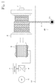
- FIG. 1 illustrates a simplified diagram of a winch that can be used for mooring a vessel according to an embodiment.
- the figure only shows components necessary for understanding the various embodiments.
- the exemplary winch comprises a winch drum 20 for spooling a spoolable medium 10, which winch drum is rotatable about an axis of rotation 21.
- the spoolable medium 10 may be a cable, a rope, a wire or a chain, for example.
- the winch further comprises a winch drive, in this example an electric drive comprising an electric motor 30, with which the winch drum 20 can be rotated.
- the electric motor 30 driving the winch drum 20 can be of any type, such as an asynchronous AC motor, such as an induction motor, a synchronous AC motor or a DC motor.
- asynchronous AC motor such as an induction motor, a synchronous AC motor or a DC motor.
- non-excited motors such as a reluctance motor, a hysteresis motor and a permanent magnet motor, and DC-excited motors, for example. It should be noted that the use of the embodiments described herein is not limited to systems employing any specific fundamental frequency or any specific voltage level, for example.
- the electric motor 30 is an induction motor and the electric dive further comprises an inverter 40 for feeding the electric motor 30 from a DC power supply 50.
- An inverter is a device used, for instance, for controlling a motor.
- the control of the electric motor 30 may be implemented reliably by means of the inverter 40 in such a manner that the motor 30 accurately implements a desired speed or torque instruction, for example.
- the exemplary embodiment further comprises a separate control unit 41 of the electric drive which may be used to control the inverter 40 and, thus, the electric motor 30 and to operate the winch.
- the control unit 41 may also be a part of the inverter 40 or some other unit, for example.
- the control unit 41 may comprise suitable I/O (Input-Output) means, such as a keyboard and display unit or another separate terminal unit, which may be connected to the control unit 41 in a wired or wireless manner.
- I/O Input-Output
- Figure 1 further illustrates a fixing point 210 for the spoolable medium 10, wherein the end of the spoolable medium 10 is to be fixed to the fixing point 210 during the mooring of the vessel.
- the winch 20, 30, 40, 41 used for the mooring of the vessel can be located in the vessel.
- the fixing point 210 for the spoolable medium 10 is located at the point of mooring, such as a mooring-post of a vessel landing place, e.g. a port or a pier, or an anchor or a buoy, for example.
- reference numeral 100 in Figure 1 refers to the vessel and reference numeral 200 refers to the point of mooring.
- the winch 20, 30, 40, 41 used for mooring the vessel can be located in the point of mooring, i.e. outside of the vessel.
- the fixing point 210 for the spoolable medium 10 is located in the vessel.
- reference numeral 200 in Figure 1 refers to the vessel and reference numeral 100 refers to the point of mooring.
- a winch for mooring a vessel can be operated as follows.
- a tension of the spoolable medium 10 between the vessel and a point of mooring is monitored.
- the tension of the spoolable medium 10 between the vessel and a point of mooring can be monitored by monitoring a torque of the electric motor 30.
- the torque of the electric motor 30 can be monitored by monitoring a current of the electric motor. It also possible to monitor the tension of the spoolable medium 10 between the vessel and a point of mooring utilizing some other quantities indicative of the tension of the spoolable medium 10.
- the monitoring of the tension of the spoolable medium 10 between the vessel and a point of mooring can be performed by the winch drive, e.g.
- control unit 41 thereof, or some other possible separate device or system. Then, in response to the monitored tension of the spoolable medium becoming higher than a first upper tension threshold or lower than a first lower tension threshold, initiating, either immediately or after a first predetermined delay, driving of the winch drum 20.
- the winch drum 20 during the driving of the winch drum 20, when the monitored tension of the spoolable medium 10 is higher than a predetermined tension set point, which has a value between the first upper tension threshold and the first lower tension threshold, the winch drum 20 is driven in such a direction that the spoolable medium 10 is spooled out, and, when the monitored tension of the spoolable medium 10 is lower than the predetermined tension set point, the winch drum 20 is driven in such a direction that the spoolable medium is spooled in.
- a predetermined tension set point which has a value between the first upper tension threshold and the first lower tension threshold
- the winch drum 20 is preferably driven into such direction in which the monitored tension of the spoolable medium tends to approach the predetermined tension set point.
- an absolute value of the driving speed of the winch drum has a value, which is proportional to an absolute value of a difference between the monitored tension of the spoolable medium and the predetermined tension set point.
- first upper tension threshold T1 u the first lower tension threshold T1l the second upper tension threshold T2u, and the second lower tension threshold T2l depend on the system characteristics and may thus vary.
- the absolute value of the driving speed of the winch drum 20 could also have a value that is proportional to an absolute value of a difference between the monitored tension of the spoolable medium and the predetermined tension set point.
- the absolute value of the driving speed of the winch drum 20 has a value that is a predetermined constant after the driving speed of the winch drum has reached said predetermined constant driving speed.
- Said constant value may be the maximum driving speed of the winch drum or a fraction thereof, for example.
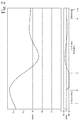
- Figure 2 illustrates an example of tension and speed diagrams according to an embodiment.
- the tension of the spoolable medium 10 goes outside the zone (hysteresis zone) defined between the first upper tension threshold T1u and the first lower tension threshold T1l by exceeding the first upper tension threshold T1 u at time point t1.
- the driving of the winch drum 20 is not initiated immediately thereafter but only after the first predetermined delay (Out-Zone delay).
- the first predetermined delay if applied, may be a few seconds or a few tens of seconds depending on system characteristics, for example, and preferably it is between 0 and 20 s, more preferably 2 s to 10 s.
- the driving of the winch drum 20 is initiated and set, optionally gradually, at a constant speed -AM_ref.
- the negative sign of the speed of the winch drum indicates that the spoolable medium 10 is spooled out.
- the tension of the spoolable medium 10 starts to gradually approach the predetermined tension set point Sp.
- the tension of the spoolable medium 10 enters the zone (dead band zone) defined between the second upper tension threshold T2u and the second lower tension threshold T2l.
- the absolute value of the driving speed of the winch drum 20 has a value that is proportional to the absolute value of the difference between the monitored tension of the spoolable medium and the predetermined tension set point Sp.
- the value of the driving speed of the winch drum 20 then varies between the maximum positive and negative speeds AM_ref, -AM_ref depending on the difference between the monitored tension of the spoolable medium and the predetermined tension set point Sp.
- the second predetermined delay In-Zone delay
- the stopping of the driving of the winch drum 20 may include controlling the speed of the winch drum 20 to zero with suitable modulation control by the inverter 40 and/or braking the winch drum 20 with a brake.
- the second predetermined delay may be a few seconds or a few tens of seconds depending on system characteristics, for example, and preferably it is between 5 s and 100 s, more preferably 15 s to 60 s.
- the absolute value of the driving speed of the winch drum may be determined according to the following equations:
- the absolute value of the driving speed of the winch drum can be directly proportional to the absolute value of the difference between the monitored tension of the spoolable medium and the predetermined tension set point.
- the invention is not limited to the above form of equations 1 and 2 but they could vary.
- the right hand sides of equations 1 and 2 could comprise a positive factor q whose value deviates from 1, i.e. q>0 and q ⁇ 1.
- the absolute value of the driving speed of the winch drum could alternatively be exponentially or logarithmically proportional to the absolute value of the difference between the monitored tension of the spoolable medium and the predetermined tension set point, for example.
- Figure 3 illustrates, according to an embodiment, speed settings in different regions of the tension of the spoolable medium 10 between the vessel and the point of mooring when the winch drum 20 is being driven.
- the speed setting is -AM_ref, i.e. spooling out.
- the speed setting is -AM_ref*([
- the speed setting is AM_ref*([
- the speed setting is AM_ref, i.e. spooling in.
- An apparatus implementing the control functions according to any one of the above embodiments, or a combination thereof, may be implemented as one unit or as two or more separate units that are configured to implement the functionality of the various embodiments.
- the term 'unit' refers generally to a physical or logical entity, such as a physical device or a part thereof or a software routine.
- One or more of these units, such as the control unit 41, may reside in an electric drive or a component thereof such as the inverter 40, for example.
- An apparatus such as the control unit 41, according to any one of the embodiments may be implemented at least partly by means of one or more computers or corresponding digital signal processing (DSP) equipment provided with suitable software, for example.
- a computer or digital signal processing equipment preferably comprises at least a working memory (RAM) providing storage area for arithmetical operations and a central processing unit (CPU), such as a general-purpose digital signal processor.
- the CPU may comprise a set of registers, an arithmetic logic unit, and a CPU control unit.
- the CPU control unit is controlled by a sequence of program instructions transferred to the CPU from the RAM.
- the CPU control unit may contain a number of microinstructions for basic operations. The implementation of microinstructions may vary depending on the CPU design.
- the program instructions may be coded by a programming language, which may be a high-level programming language, such as C, Java, etc., or a low-level programming language, such as a machine language, or an assembler.
- the computer may also have an operating system which may provide system services to a computer program written with the program instructions.
- the computer or other apparatus implementing the invention, or a part thereof, may further comprise suitable input means for receiving e.g. measurement and/or control data, and output means for outputting e.g. control data. It is also possible to use a specific integrated circuit or circuits, or discrete electric components and devices for implementing the functionality according to any one of the embodiments.
- the invention can be implemented in existing system elements, such as electric drives or components thereof, such as inverters or frequency converters, or similar devices, or by using separate dedicated elements or devices in a centralized or distributed manner.
- Present devices for electric drives, such as inverters and frequency converters typically comprise processors and memory that can be utilized in the functions according to embodiments of the invention.
- all modifications and configurations required for implementing an embodiment of the invention e.g. in existing devices may be performed as software routines, which may be implemented as added or updated software routines.
- Such software can be provided as a computer program product comprising computer program code which, when run on a computer, causes the computer or corresponding arrangement to perform the functionality according to the invention as described above.
- a computer program code may be stored or generally embodied on a computer readable medium, such as suitable memory, e.g. a flash memory or a disc memory from which it is loadable to the unit or units executing the program code.
- suitable memory e.g. a flash memory or a disc memory from which it is loadable to the unit or units executing the program code.
- a computer program code implementing the invention may be loaded to the unit or units executing the computer program code via a suitable data network, for example, and it may replace or update a possibly existing program code.
Landscapes
- Engineering & Computer Science (AREA)
- Mechanical Engineering (AREA)
- Chemical & Material Sciences (AREA)
- Combustion & Propulsion (AREA)
- Ocean & Marine Engineering (AREA)
- Microelectronics & Electronic Packaging (AREA)
- Power Engineering (AREA)
- Control Of Electric Motors In General (AREA)
- Control And Safety Of Cranes (AREA)
- Tension Adjustment In Filamentary Materials (AREA)
- Control Of Ac Motors In General (AREA)
Abstract
Description
- The invention relates to operating a winch, in particular a winch comprising a winch drum for spooling a spoolable medium for mooring a vessel, and to a winch.
- Winches can be used for mooring a vessel. Such a vessel may be a ship, a boat or generally a craft designed for water transportation in a sea, an ocean, a lake, a river, a channel, a canal, or any parts thereof, for example.
- Such a winch used for the mooring may comprise a winch drum which is rotatable about an axis of rotation thereof and may be used for spooling a spoolable medium, which is to be connected to a point of mooring. The spoolable medium may comprise a cable, a rope, a wire or a chain, for example. The point of mooring may be any point where the vessel can be moored, such as a mooring-post of a vessel landing place, e.g. a port or a pier, or an anchor or a buoy, for example. The winch used for the mooring may further comprise an electric motor drive comprising an electric motor, which is configured to rotate the winch drum about the axis of rotation thereof during spooling in or spooling out of the spoolable medium. The electric motor drive can be an AC drive or a DC drive and the electric motor can be an AC motor, such as an asynchronous motor (induction motor) or a synchronous motor, or a DC motor, respectively, for example.
- In a vessel, the mooring functionality of the winch used for mooring can control the spoolable medium that holds the vessel in place at the point of mooring by means of the electric motor drive. When the vessel is being moored, the tension of the spoolable medium between the vessel and the point of mooring can be automatically adjusted by suitably controlling the electric motor drive that controls the winch used for mooring. The tension of the spoolable medium between the vessel and a point of mooring should be kept at an appropriate level. If the spoolable medium between the vessel and the point of mooring is too loose, the vessel will not stay in place, and if the spoolable medium is too tight, the spoolable medium might break or the operation might become unstable.
- The electric drive can be controlled such that when the tension of the spoolable medium between the vessel and a point of mooring is outside a predetermined hysteresis zone, the spoolable medium is either tightened (spooled in) or loosened (spooled out) at a predetermined constant driving speed of the winch drum towards a predetermined tension set point. And when the tension of the spoolable medium between the vessel and the point of mooring has been inside a predetermined dead band zone, located within the hysteresis zone, for a certain predetermined period of time, the tightening or loosening is stopped.
- Controlling the adjustment of the spoolable medium smoothly close to the predetermined tension set point is desirable. However, in the above solution, oscillations around the predetermined tension set point can easily occur and resulting sudden stops can be harmful to the mechanics of the winch and the spoolable medium, for example.
- The object of the invention is thus to provide a method and an apparatus for implementing the method so as to solve or at least alleviate the above problem. The object of the invention is achieved with a method, a computer program product, and a winch that are characterized by what is stated in the independent claims. Preferred embodiments of the invention are described in the dependent claims.
- The invention is based on the idea that an absolute value of the driving speed of the winch, when spooling in or out the spoolable medium, is set proportional to an absolute value of a difference between a monitored tension of the spoolable medium between the vessel and a point of mooring and a predetermined tension set point, at least when the monitored tension of the spoolable medium is inside a predetermined dead band zone.
- An advantage of the invention is that the tension control of the spoolable medium around the predetermined tension set point is smooth and well-controlled. Moreover, such proportional speed control will reduce any oscillations around the predetermined tension set point. This can improve the reliability of the operation of the winch and extend the lifetime of the spoolable medium.
- In the following, the invention will be described in more detail in connection with preferred embodiments with reference to the accompanying drawings, in which
-
Figure 1 illustrates a diagram of a winch according to an embodiment; -
Figure 2 illustrates tension and speed diagrams according to an embodiment; and -
Figure 3 illustrates speeds in different tension regions according to an embodiment. -
Figure 1 illustrates a simplified diagram of a winch that can be used for mooring a vessel according to an embodiment. The figure only shows components necessary for understanding the various embodiments. The exemplary winch comprises awinch drum 20 for spooling a spoolable medium 10, which winch drum is rotatable about an axis ofrotation 21. The spoolable medium 10 may be a cable, a rope, a wire or a chain, for example. In the example ofFigure 1 , the winch further comprises a winch drive, in this example an electric drive comprising anelectric motor 30, with which thewinch drum 20 can be rotated. Theelectric motor 30 driving thewinch drum 20 can be of any type, such as an asynchronous AC motor, such as an induction motor, a synchronous AC motor or a DC motor. Possible examples of the synchronous AC motor include non-excited motors, such as a reluctance motor, a hysteresis motor and a permanent magnet motor, and DC-excited motors, for example. It should be noted that the use of the embodiments described herein is not limited to systems employing any specific fundamental frequency or any specific voltage level, for example. In the example ofFigure 1 , theelectric motor 30 is an induction motor and the electric dive further comprises aninverter 40 for feeding theelectric motor 30 from aDC power supply 50. An inverter is a device used, for instance, for controlling a motor. The control of theelectric motor 30 may be implemented reliably by means of theinverter 40 in such a manner that themotor 30 accurately implements a desired speed or torque instruction, for example. The exemplary embodiment further comprises aseparate control unit 41 of the electric drive which may be used to control theinverter 40 and, thus, theelectric motor 30 and to operate the winch. Thecontrol unit 41 may also be a part of theinverter 40 or some other unit, for example. Thecontrol unit 41 may comprise suitable I/O (Input-Output) means, such as a keyboard and display unit or another separate terminal unit, which may be connected to thecontrol unit 41 in a wired or wireless manner. Thus, an operator or user of the system can operate the winch through the I/O means. -
Figure 1 further illustrates afixing point 210 for the spoolable medium 10, wherein the end of the spoolable medium 10 is to be fixed to thefixing point 210 during the mooring of the vessel. According to an embodiment, thewinch fixing point 210 for the spoolable medium 10 is located at the point of mooring, such as a mooring-post of a vessel landing place, e.g. a port or a pier, or an anchor or a buoy, for example. According to this alternative,reference numeral 100 inFigure 1 refers to the vessel andreference numeral 200 refers to the point of mooring. According to an alternative embodiment, thewinch fixing point 210 for the spoolable medium 10 is located in the vessel. According to this alternative embodiment,reference numeral 200 inFigure 1 refers to the vessel andreference numeral 100 refers to the point of mooring. - According to an embodiment, a winch for mooring a vessel can be operated as follows. A tension of the spoolable medium 10 between the vessel and a point of mooring is monitored. According to an embodiment, the tension of the spoolable medium 10 between the vessel and a point of mooring can be monitored by monitoring a torque of the
electric motor 30. According to an embodiment, the torque of theelectric motor 30 can be monitored by monitoring a current of the electric motor. It also possible to monitor the tension of the spoolable medium 10 between the vessel and a point of mooring utilizing some other quantities indicative of the tension of thespoolable medium 10. The monitoring of the tension of the spoolable medium 10 between the vessel and a point of mooring can be performed by the winch drive, e.g. by thecontrol unit 41 thereof, or some other possible separate device or system. Then, in response to the monitored tension of the spoolable medium becoming higher than a first upper tension threshold or lower than a first lower tension threshold, initiating, either immediately or after a first predetermined delay, driving of thewinch drum 20. According to an embodiment, during the driving of thewinch drum 20, when the monitored tension of the spoolable medium 10 is higher than a predetermined tension set point, which has a value between the first upper tension threshold and the first lower tension threshold, thewinch drum 20 is driven in such a direction that the spoolable medium 10 is spooled out, and, when the monitored tension of the spoolable medium 10 is lower than the predetermined tension set point, thewinch drum 20 is driven in such a direction that the spoolable medium is spooled in. In other words, if the monitored tension of the spoolable medium 10 deviates from the predetermined tension set point during the driving of thewinch drum 20, thewinch drum 20 is preferably driven into such direction in which the monitored tension of the spoolable medium tends to approach the predetermined tension set point. Moreover, according to an embodiment, during the driving of thewinch drum 20, at least when the monitored tension of thespoolable medium 10 is between a second upper tension threshold, which has a value equal to or lower than the first upper tension threshold but higher than the predetermined tension set point, and a second lower tension threshold, which has a value equal to or higher than the first lower tension threshold but lower than the predetermined tension set point, an absolute value of the driving speed of the winch drum has a value, which is proportional to an absolute value of a difference between the monitored tension of the spoolable medium and the predetermined tension set point. And, in response to the monitored tension of thespoolable medium 10 being, during the driving of thewinch drum 20, between the second upper tension threshold and the second lower tension threshold for a second predetermined delay, stopping the driving of thewinch drum 20. The values of the first upper tension threshold T1 u, the first lower tension threshold T1l the second upper tension threshold T2u, and the second lower tension threshold T2l depend on the system characteristics and may thus vary. - When the monitored tension of the spoolable medium 10 is higher than the second upper tension threshold, or when the monitored tension of the spoolable medium 10 is lower than the second lower tension threshold, the absolute value of the driving speed of the
winch drum 20 could also have a value that is proportional to an absolute value of a difference between the monitored tension of the spoolable medium and the predetermined tension set point. Alternatively, according to an embodiment, during the driving of thewinch drum 20, when the monitored tension of the spoolable medium 10 is higher than the second upper tension threshold, or when the monitored tension of the spoolable medium 10 is lower than the second lower tension threshold, the absolute value of the driving speed of thewinch drum 20 has a value that is a predetermined constant after the driving speed of the winch drum has reached said predetermined constant driving speed. In this case, there may be an initial period where the driving speed is gradually increased to said predetermined constant value after which the driving speed is kept at said constant value. Said constant value may be the maximum driving speed of the winch drum or a fraction thereof, for example. Using such essentially constant driving speed instead of a variable speed based on the difference between the monitored tension of the spoolable medium and the predetermined tension set point, when the tension of the spoolable medium 10 is higher than the second upper tension threshold or lower than the second lower tension threshold may be advantageous in order to initially provide a higher speed of spooling, for example. -
Figure 2 illustrates an example of tension and speed diagrams according to an embodiment. In the example ofFigure 2 the tension of the spoolable medium 10 goes outside the zone (hysteresis zone) defined between the first upper tension threshold T1u and the first lower tension threshold T1l by exceeding the first upper tension threshold T1 u at time point t1. In this example the driving of thewinch drum 20 is not initiated immediately thereafter but only after the first predetermined delay (Out-Zone delay). The first predetermined delay, if applied, may be a few seconds or a few tens of seconds depending on system characteristics, for example, and preferably it is between 0 and 20 s, more preferably 2 s to 10 s. After the first predetermined delay, at time point t2 the driving of thewinch drum 20 is initiated and set, optionally gradually, at a constant speed -AM_ref. In this example the negative sign of the speed of the winch drum indicates that the spoolable medium 10 is spooled out. As a result, the tension of the spoolable medium 10 starts to gradually approach the predetermined tension set point Sp. At time point t3 the tension of the spoolable medium 10 enters the zone (dead band zone) defined between the second upper tension threshold T2u and the second lower tension threshold T2l. As a result, the absolute value of the driving speed of thewinch drum 20 has a value that is proportional to the absolute value of the difference between the monitored tension of the spoolable medium and the predetermined tension set point Sp. The value of the driving speed of thewinch drum 20 then varies between the maximum positive and negative speeds AM_ref, -AM_ref depending on the difference between the monitored tension of the spoolable medium and the predetermined tension set point Sp. After the second predetermined delay (In-Zone delay) after entering the zone defined between the second upper tension threshold T2u and the second lower tension threshold T2l, i.e. at time point t4, the driving of thewinch drum 20 is stopped. The stopping of the driving of thewinch drum 20 may include controlling the speed of thewinch drum 20 to zero with suitable modulation control by theinverter 40 and/or braking thewinch drum 20 with a brake. The second predetermined delay may be a few seconds or a few tens of seconds depending on system characteristics, for example, and preferably it is between 5 s and 100 s, more preferably 15 s to 60 s. - According to an embodiment, the absolute value of the driving speed of the winch drum may be determined according to the following equations:
- a) when the monitored tension of the spoolable medium is between the second upper tension threshold T2u and the predetermined tension set point Sp:

- b) when the monitored tension of the spoolable medium is between the second lower tension threshold T2l and the predetermined tension set point Sp:

- Ref = the speed of the winch drum
- AM_ref = a predetermined constant
- Rt = the monitored tension of the spoolable medium
- Sp = the predetermined tension set point
- T2u = the second upper tension threshold
- T2l = the second lower tension threshold.
- Thus, according to equations 1 and 2, when the monitored tension of the spoolable medium 10 is between the second upper tension threshold and the second lower tension threshold, the absolute value of the driving speed of the winch drum can be directly proportional to the absolute value of the difference between the monitored tension of the spoolable medium and the predetermined tension set point. It should be noted that the invention is not limited to the above form of equations 1 and 2 but they could vary. For example, the right hand sides of equations 1 and 2 could comprise a positive factor q whose value deviates from 1, i.e. q>0 and q≠1. Moreover, the absolute value of the driving speed of the winch drum could alternatively be exponentially or logarithmically proportional to the absolute value of the difference between the monitored tension of the spoolable medium and the predetermined tension set point, for example.
-
Figure 3 illustrates, according to an embodiment, speed settings in different regions of the tension of the spoolable medium 10 between the vessel and the point of mooring when thewinch drum 20 is being driven. According to this example, when the tension is higher than the second upper tension threshold T2u, the speed setting is -AM_ref, i.e. spooling out. Between the second upper tension threshold T2u and the predetermined tension set point Sp, the speed setting is -AM_ref*([|Rt-Sp|]/[|T2u-Sp|]), i.e. spooling out. Between the second lower tension threshold T2| and the predetermined tension set point Sp, the speed setting is AM_ref*([|Rt-Sp|]/[|T2|-Sp|]), i.e. spooling in. And, when the tension is lower than the second lower tension threshold T2|, the speed setting is AM_ref, i.e. spooling in. - An apparatus implementing the control functions according to any one of the above embodiments, or a combination thereof, may be implemented as one unit or as two or more separate units that are configured to implement the functionality of the various embodiments. Here the term 'unit' refers generally to a physical or logical entity, such as a physical device or a part thereof or a software routine. One or more of these units, such as the
control unit 41, may reside in an electric drive or a component thereof such as theinverter 40, for example. - An apparatus, such as the
control unit 41, according to any one of the embodiments may be implemented at least partly by means of one or more computers or corresponding digital signal processing (DSP) equipment provided with suitable software, for example. Such a computer or digital signal processing equipment preferably comprises at least a working memory (RAM) providing storage area for arithmetical operations and a central processing unit (CPU), such as a general-purpose digital signal processor. The CPU may comprise a set of registers, an arithmetic logic unit, and a CPU control unit. The CPU control unit is controlled by a sequence of program instructions transferred to the CPU from the RAM. The CPU control unit may contain a number of microinstructions for basic operations. The implementation of microinstructions may vary depending on the CPU design. The program instructions may be coded by a programming language, which may be a high-level programming language, such as C, Java, etc., or a low-level programming language, such as a machine language, or an assembler. The computer may also have an operating system which may provide system services to a computer program written with the program instructions. The computer or other apparatus implementing the invention, or a part thereof, may further comprise suitable input means for receiving e.g. measurement and/or control data, and output means for outputting e.g. control data. It is also possible to use a specific integrated circuit or circuits, or discrete electric components and devices for implementing the functionality according to any one of the embodiments. - The invention according to any one of the embodiments, or any combination thereof, can be implemented in existing system elements, such as electric drives or components thereof, such as inverters or frequency converters, or similar devices, or by using separate dedicated elements or devices in a centralized or distributed manner. Present devices for electric drives, such as inverters and frequency converters, typically comprise processors and memory that can be utilized in the functions according to embodiments of the invention. Thus, all modifications and configurations required for implementing an embodiment of the invention e.g. in existing devices may be performed as software routines, which may be implemented as added or updated software routines. If the functionality of the invention is implemented by software, such software can be provided as a computer program product comprising computer program code which, when run on a computer, causes the computer or corresponding arrangement to perform the functionality according to the invention as described above. Such a computer program code may be stored or generally embodied on a computer readable medium, such as suitable memory, e.g. a flash memory or a disc memory from which it is loadable to the unit or units executing the program code. In addition, such a computer program code implementing the invention may be loaded to the unit or units executing the computer program code via a suitable data network, for example, and it may replace or update a possibly existing program code.
- It is obvious to a person skilled in the art that as technology advances, the basic idea of the invention can be implemented in a variety of ways. Consequently, the invention and its embodiments are not restricted to the above examples, but can vary within the scope of the claims.
Claims (15)
- A method for operating a winch comprising a winch drum (20) for spooling a spoolable medium (10) for mooring a vessel, the method comprising:monitoring a tension of the spoolable medium (10) between the vessel and a point of mooring;in response to the monitored tension of the spoolable medium (10) becoming higher than a first upper tension threshold (T1u) or lower than a first lower tension threshold (T1l), initiating, either immediately or after a first predetermined delay, driving of the winch drum (20),wherein, during the driving of the winch drum (20), when the monitored tension of the spoolable medium (10) is higher than a predetermined tension set point (Sp), which has a value between the first upper tension threshold and the first lower tension threshold, the winch drum is driven in such a direction that the spoolable medium is spooled out,wherein, during the driving of the winch drum (20), when the monitored tension of the spoolable medium (10) is lower than the predetermined tension set point (Sp), the winch drum is driven in such a direction that the spoolable medium is spooled in, andwherein, during the driving of the winch drum (20), at least when the monitored tension of the spoolable medium (10) is between a second upper tension threshold (T2u), which has a value equal to or lower than the first upper tension threshold (T1 u) but higher than the predetermined tension set point (Sp), and a second lower tension threshold (T2l), which has a value equal to or higher than the first lower tension threshold (T1l) but lower than the predetermined tension set point (Sp), an absolute value of the driving speed of the winch drum has a value that is proportional to an absolute value of a difference between the monitored tension of the spoolable medium and the predetermined tension set point (Sp); andin response to the monitored tension of the spoolable medium (10) being, during the driving of the winch drum (20), between the second upper tension threshold (T2u) and the second lower tension threshold (T2l) for a second predetermined delay, stopping the driving of the winch drum.
- A method as claimed in claim 1, wherein, during the driving of the winch drum (20), when the monitored tension of the spoolable medium (10) is higher than the second upper tension threshold (T2u), or when the monitored tension of the spoolable medium (10) is lower than the second lower tension threshold (T2l), the absolute value of the driving speed of the winch drum has a value that is a predetermined constant after the driving speed of the winch drum has reached said predetermined constant driving speed.
- A method as claimed in claim 1 or 2, wherein the value of the absolute value of the driving speed of the winch drum (20) is determined according to the following equations:when the monitored tension of the spoolable medium is between the second upper tension threshold and the predetermined tension set point:
 when the monitored tension of the spoolable medium is between the second lower tension threshold and the predetermined tension set point:
 Ref = the speed of the winch drumAM_ref = a predetermined constantRt = the monitored tension of the spoolable medium Sp = the predetermined tension set pointT2u = the second upper tension thresholdT2l = the second lower tension threshold.
 - A method as claimed in claim 1, 2 or 3, wherein the winch drum (20) is driven by an electric motor (30).
- A method as claimed in claim 4, wherein the tension of the spoolable medium (10) between the vessel and a point of mooring is monitored by monitoring a torque of the electric motor (30).
- A method as claimed in claim 5, wherein the torque of the electric motor (30) is monitored by monitoring a current of the electric motor.
- A computer program product comprising computer program code, wherein execution of the program code in a computer causes the computer to carry out the steps of the method according to any one of claims 1 to 6.
- A winch comprising:a winch drum (20) for spooling a spoolable medium (10) for mooring a vessel; anda winch drive (30, 40, 41) for driving the winch drum, the winch drive being configured to:monitor a tension of the spoolable medium (10) between the vessel and a point of mooring;in response to the monitored tension of the spoolable medium (10) becoming higher than a first upper tension threshold or lower than a first lower tension threshold, initiate, either immediately or after a first predetermined delay, driving of the winch drum (20),wherein, during the driving of the winch drum (20), when the monitored tension of the spoolable medium (10) is higher than a predetermined tension set point, which has a value between the first upper tension threshold and the first lower tension threshold, the winch drive is configured to drive the winch drum in such a direction that the spoolable medium is spooled out,wherein, during the driving of the winch drum (20), when the monitored tension of the spoolable medium (10) is lower than the predetermined tension set point, the winch drive is configured to drive the winch drum in such a direction that the spoolable medium is spooled in, andwherein, during the driving of the winch drum (20), at least when the monitored tension of the spoolable medium (10) is between a second upper tension threshold, which has a value equal to or lower than the first upper tension threshold but higher than the predetermined tension set point, and a second lower tension threshold, which has a value equal to or higher than the first lower tension threshold but lower than the predetermined tension set point, an absolute value of the driving speed of the winch drum is configured to have a value that is proportional to an absolute value of a difference between the monitored tension of the spoolable medium and the predetermined tension set point; andin response to the monitored tension of the spoolable medium (10) being, during the driving of the winch drum (20), between the second upper tension threshold and the second lower tension threshold for a second predetermined delay, stop the driving of the winch drum.
- A winch as claimed in claim 8, wherein, during the driving of the winch drum (20), when the monitored tension of the spoolable medium (10) is higher than the second upper tension threshold or when the monitored tension of the spoolable medium (10) is lower than the second lower tension threshold, the absolute value of the driving speed of the winch drum is configured to have a value, which is a predetermined constant after the driving speed of the winch drum has reached said predetermined constant driving speed.
- A winch as claimed in claim 8 or 9, wherein the winch drive (30, 40, 41) is configured to determine the second value of the absolute value of the driving speed of the winch drum (20) according to the following equations:when the monitored tension of the spoolable medium is between the second upper tension threshold and the predetermined tension set point:
 when the monitored tension of the spoolable medium is between the second lower tension threshold and the predetermined tension set point:
 Ref = the speed of the winch drumAM_ref = a predetermined constantRt = the monitored tension of the spoolable medium Sp = the predetermined tension set pointT2u = the second upper tension thresholdT2l = the second lower tension threshold.
 - A winch as claimed in claim 8, 9 or 10, wherein the winch drive (30, 40, 41) comprises an electric motor (30) for driving the winch drum.
- A winch as claimed in claim 11, wherein the winch drive (30, 40, 41) is configured to monitor the tension of the spoolable medium (10) between the vessel and a point of mooring by monitoring a torque of the electric motor (30).
- A winch as claimed in claim 12, wherein the winch drive (30, 40, 41) is configured to monitor the torque of the electric motor (30) by monitoring a current of the electric motor.
- A winch as claimed in any one of claims 11 to 13, wherein the electric motor (30) is an AC motor or a DC motor.
- A winch as claimed in any one of claims 8 to 14, wherein the spoolable medium (10) is a cable, a rope, a wire or a chain.
Priority Applications (5)
| Application Number | Priority Date | Filing Date | Title |
|---|---|---|---|
| EP16151423.7A EP3192766B1 (en) | 2016-01-15 | 2016-01-15 | Method for operating winch, and winch |
| CN201710017207.3A CN107021185A (en) | 2016-01-15 | 2017-01-10 | Method and capstan winch for operating capstan winch |
| KR1020170004879A KR101888047B1 (en) | 2016-01-15 | 2017-01-12 | Method for operating winch, and winch |
| US15/406,180 US10589968B2 (en) | 2016-01-15 | 2017-01-13 | Method for operating winch, and winch |
| JP2017004247A JP6464347B2 (en) | 2016-01-15 | 2017-01-13 | Winch operating method and winch |
Applications Claiming Priority (1)
| Application Number | Priority Date | Filing Date | Title |
|---|---|---|---|
| EP16151423.7A EP3192766B1 (en) | 2016-01-15 | 2016-01-15 | Method for operating winch, and winch |
Publications (2)
| Publication Number | Publication Date |
|---|---|
| EP3192766A1 true EP3192766A1 (en) | 2017-07-19 |
| EP3192766B1 EP3192766B1 (en) | 2020-07-08 |
Family
ID=55177755
Family Applications (1)
| Application Number | Title | Priority Date | Filing Date |
|---|---|---|---|
| EP16151423.7A Active EP3192766B1 (en) | 2016-01-15 | 2016-01-15 | Method for operating winch, and winch |
Country Status (5)
| Country | Link |
|---|---|
| US (1) | US10589968B2 (en) |
| EP (1) | EP3192766B1 (en) |
| JP (1) | JP6464347B2 (en) |
| KR (1) | KR101888047B1 (en) |
| CN (1) | CN107021185A (en) |
Families Citing this family (9)
| Publication number | Priority date | Publication date | Assignee | Title |
|---|---|---|---|---|
| EP3539918B1 (en) * | 2018-03-14 | 2025-07-30 | ABB Schweiz AG | Method for operating winch and electric drive for driving winch |
| CN108945351A (en) * | 2018-06-05 | 2018-12-07 | 罗达 | A kind of portable secured lifesaving guarantee tool |
| EP3647252B1 (en) * | 2018-10-31 | 2025-07-30 | ABB Schweiz AG | Method for operating towing winch and electric drive for towing winch |
| US11414309B2 (en) * | 2018-12-12 | 2022-08-16 | Caterpillar Inc. | System for controlling the operation of an electric winch |
| US11339038B2 (en) * | 2018-12-12 | 2022-05-24 | Caterpillar Inc. | System for controlling the operation of a hydraulic winch |
| EP3909905A1 (en) * | 2020-05-15 | 2021-11-17 | ABB Schweiz AG | Method for operating winch system, and winch system |
| CN114408783A (en) * | 2021-12-24 | 2022-04-29 | 宜昌测试技术研究所 | A constant tension traction and cable storage winch control system |
| KR102745183B1 (en) * | 2022-09-14 | 2024-12-24 | 유원산업(주) | Method of Bidirectional Tension Winch Control For Shipping |
| US20240324582A1 (en) * | 2023-03-28 | 2024-10-03 | William Nicol Kittredge | Method and system for invasive vine removal from trees |
Citations (3)
| Publication number | Priority date | Publication date | Assignee | Title |
|---|---|---|---|---|
| GB1212442A (en) * | 1967-02-23 | 1970-11-18 | Abex Corp | Method and apparatus for cable tension control |
| US20100116191A1 (en) * | 2008-11-10 | 2010-05-13 | Abb Oy | Mooring winch and a method for controlling a cable of a mooring winch |
| EP2385011A1 (en) * | 2010-05-07 | 2011-11-09 | ABB Oy | A mooring winch and a method for controlling a cable of a mooring winch |
Family Cites Families (11)
| Publication number | Priority date | Publication date | Assignee | Title |
|---|---|---|---|---|
| US2385011A (en) * | 1941-09-03 | 1945-09-18 | Lurtz Carl | Escapement mechanism |
| US3693939A (en) * | 1971-04-22 | 1972-09-26 | All American Ind | Tension control system |
| GB1567471A (en) * | 1976-02-28 | 1980-05-14 | Ferranti Ltd | Load transfer |
| JPS541559A (en) * | 1977-06-06 | 1979-01-08 | Mitsubishi Electric Corp | Automatic controller of tension of mooring winch |
| JPS5642499U (en) * | 1979-09-12 | 1981-04-18 | ||
| JPS58148188A (en) * | 1982-02-24 | 1983-09-03 | 神鋼電機株式会社 | Controller for winch for constant-tension mooring |
| JPS60252593A (en) * | 1984-05-28 | 1985-12-13 | 株式会社北川鉄工所 | Rope tension control method in winch |
| JP2002003178A (en) * | 2000-06-26 | 2002-01-09 | Hitachi Zosen Corp | Offshore supply winch |
| CN102336376A (en) * | 2010-07-26 | 2012-02-01 | 上海派恩科技有限公司 | Cable taking-up/paying-off control system of hydrographic winch |
| CN104671140B (en) * | 2013-11-28 | 2017-01-11 | 中国科学院沈阳自动化研究所 | PLC-based (programmable logic controller) cable laying ship hoisting and dragging control method |
| CN104443275A (en) * | 2014-10-09 | 2015-03-25 | 武汉船用机械有限责任公司 | Master-slave control system for automatically tensioning winch mooring rope of anchor moored positioning system |
-
2016
- 2016-01-15 EP EP16151423.7A patent/EP3192766B1/en active Active
-
2017
- 2017-01-10 CN CN201710017207.3A patent/CN107021185A/en active Pending
- 2017-01-12 KR KR1020170004879A patent/KR101888047B1/en active Active
- 2017-01-13 JP JP2017004247A patent/JP6464347B2/en active Active
- 2017-01-13 US US15/406,180 patent/US10589968B2/en active Active
Patent Citations (3)
| Publication number | Priority date | Publication date | Assignee | Title |
|---|---|---|---|---|
| GB1212442A (en) * | 1967-02-23 | 1970-11-18 | Abex Corp | Method and apparatus for cable tension control |
| US20100116191A1 (en) * | 2008-11-10 | 2010-05-13 | Abb Oy | Mooring winch and a method for controlling a cable of a mooring winch |
| EP2385011A1 (en) * | 2010-05-07 | 2011-11-09 | ABB Oy | A mooring winch and a method for controlling a cable of a mooring winch |
Also Published As
| Publication number | Publication date |
|---|---|
| KR20170085974A (en) | 2017-07-25 |
| US10589968B2 (en) | 2020-03-17 |
| JP6464347B2 (en) | 2019-02-06 |
| EP3192766B1 (en) | 2020-07-08 |
| KR101888047B1 (en) | 2018-09-06 |
| CN107021185A (en) | 2017-08-08 |
| JP2017124943A (en) | 2017-07-20 |
| US20170203940A1 (en) | 2017-07-20 |
Similar Documents
| Publication | Publication Date | Title |
|---|---|---|
| EP3192766B1 (en) | Method for operating winch, and winch | |
| EP3539918B1 (en) | Method for operating winch and electric drive for driving winch | |
| CN111114691B (en) | Method for operating a towing winch and electric drive for a towing winch | |
| EP2921448B1 (en) | Method for operating winch, and winch | |
| EP2385011B1 (en) | A mooring winch and a method for controlling a cable of a mooring winch | |
| JP5179457B2 (en) | Method for controlling mooring winches and cables for mooring winches | |
| EP3170784B1 (en) | Method for operating anchor winch, and anchor winch | |
| US12151785B2 (en) | Method for operating winch system, and winch system | |
| EP3647253A1 (en) | Method for operating winch and electric drive for winch |
Legal Events
| Date | Code | Title | Description |
|---|---|---|---|
| PUAI | Public reference made under article 153(3) epc to a published international application that has entered the european phase |
Free format text: ORIGINAL CODE: 0009012 |
|
| STAA | Information on the status of an ep patent application or granted ep patent |
Free format text: STATUS: THE APPLICATION HAS BEEN PUBLISHED |
|
| AK | Designated contracting states |
Kind code of ref document: A1 Designated state(s): AL AT BE BG CH CY CZ DE DK EE ES FI FR GB GR HR HU IE IS IT LI LT LU LV MC MK MT NL NO PL PT RO RS SE SI SK SM TR |
|
| AX | Request for extension of the european patent |
Extension state: BA ME |
|
| STAA | Information on the status of an ep patent application or granted ep patent |
Free format text: STATUS: REQUEST FOR EXAMINATION WAS MADE |
|
| 17P | Request for examination filed |
Effective date: 20171213 |
|
| RBV | Designated contracting states (corrected) |
Designated state(s): AL AT BE BG CH CY CZ DE DK EE ES FI FR GB GR HR HU IE IS IT LI LT LU LV MC MK MT NL NO PL PT RO RS SE SI SK SM TR |
|
| RAP1 | Party data changed (applicant data changed or rights of an application transferred) |
Owner name: ABB SCHWEIZ AG |
|
| STAA | Information on the status of an ep patent application or granted ep patent |
Free format text: STATUS: EXAMINATION IS IN PROGRESS |
|
| 17Q | First examination report despatched |
Effective date: 20190408 |
|
| GRAP | Despatch of communication of intention to grant a patent |
Free format text: ORIGINAL CODE: EPIDOSNIGR1 |
|
| STAA | Information on the status of an ep patent application or granted ep patent |
Free format text: STATUS: GRANT OF PATENT IS INTENDED |
|
| INTG | Intention to grant announced |
Effective date: 20200123 |
|
| GRAS | Grant fee paid |
Free format text: ORIGINAL CODE: EPIDOSNIGR3 |
|
| GRAA | (expected) grant |
Free format text: ORIGINAL CODE: 0009210 |
|
| STAA | Information on the status of an ep patent application or granted ep patent |
Free format text: STATUS: THE PATENT HAS BEEN GRANTED |
|
| RAP1 | Party data changed (applicant data changed or rights of an application transferred) |
Owner name: ABB SCHWEIZ AG |
|
| AK | Designated contracting states |
Kind code of ref document: B1 Designated state(s): AL AT BE BG CH CY CZ DE DK EE ES FI FR GB GR HR HU IE IS IT LI LT LU LV MC MK MT NL NO PL PT RO RS SE SI SK SM TR |
|
| REG | Reference to a national code |
Ref country code: AT Ref legal event code: REF Ref document number: 1288253 Country of ref document: AT Kind code of ref document: T Effective date: 20200715 Ref country code: CH Ref legal event code: EP |
|
| REG | Reference to a national code |
Ref country code: DE Ref legal event code: R096 Ref document number: 602016039370 Country of ref document: DE |
|
| REG | Reference to a national code |
Ref country code: IE Ref legal event code: FG4D |
|
| REG | Reference to a national code |
Ref country code: LT Ref legal event code: MG4D |
|
| REG | Reference to a national code |
Ref country code: AT Ref legal event code: MK05 Ref document number: 1288253 Country of ref document: AT Kind code of ref document: T Effective date: 20200708 |
|
| REG | Reference to a national code |
Ref country code: NL Ref legal event code: MP Effective date: 20200708 |
|
| PG25 | Lapsed in a contracting state [announced via postgrant information from national office to epo] |
Ref country code: SE Free format text: LAPSE BECAUSE OF FAILURE TO SUBMIT A TRANSLATION OF THE DESCRIPTION OR TO PAY THE FEE WITHIN THE PRESCRIBED TIME-LIMIT Effective date: 20200708 Ref country code: HR Free format text: LAPSE BECAUSE OF FAILURE TO SUBMIT A TRANSLATION OF THE DESCRIPTION OR TO PAY THE FEE WITHIN THE PRESCRIBED TIME-LIMIT Effective date: 20200708 Ref country code: AT Free format text: LAPSE BECAUSE OF FAILURE TO SUBMIT A TRANSLATION OF THE DESCRIPTION OR TO PAY THE FEE WITHIN THE PRESCRIBED TIME-LIMIT Effective date: 20200708 Ref country code: GR Free format text: LAPSE BECAUSE OF FAILURE TO SUBMIT A TRANSLATION OF THE DESCRIPTION OR TO PAY THE FEE WITHIN THE PRESCRIBED TIME-LIMIT Effective date: 20201009 Ref country code: NO Free format text: LAPSE BECAUSE OF FAILURE TO SUBMIT A TRANSLATION OF THE DESCRIPTION OR TO PAY THE FEE WITHIN THE PRESCRIBED TIME-LIMIT Effective date: 20201008 Ref country code: ES Free format text: LAPSE BECAUSE OF FAILURE TO SUBMIT A TRANSLATION OF THE DESCRIPTION OR TO PAY THE FEE WITHIN THE PRESCRIBED TIME-LIMIT Effective date: 20200708 Ref country code: PT Free format text: LAPSE BECAUSE OF FAILURE TO SUBMIT A TRANSLATION OF THE DESCRIPTION OR TO PAY THE FEE WITHIN THE PRESCRIBED TIME-LIMIT Effective date: 20201109 Ref country code: BG Free format text: LAPSE BECAUSE OF FAILURE TO SUBMIT A TRANSLATION OF THE DESCRIPTION OR TO PAY THE FEE WITHIN THE PRESCRIBED TIME-LIMIT Effective date: 20201008 Ref country code: LT Free format text: LAPSE BECAUSE OF FAILURE TO SUBMIT A TRANSLATION OF THE DESCRIPTION OR TO PAY THE FEE WITHIN THE PRESCRIBED TIME-LIMIT Effective date: 20200708 Ref country code: FI Free format text: LAPSE BECAUSE OF FAILURE TO SUBMIT A TRANSLATION OF THE DESCRIPTION OR TO PAY THE FEE WITHIN THE PRESCRIBED TIME-LIMIT Effective date: 20200708 |
|
| PG25 | Lapsed in a contracting state [announced via postgrant information from national office to epo] |
Ref country code: IS Free format text: LAPSE BECAUSE OF FAILURE TO SUBMIT A TRANSLATION OF THE DESCRIPTION OR TO PAY THE FEE WITHIN THE PRESCRIBED TIME-LIMIT Effective date: 20201108 Ref country code: PL Free format text: LAPSE BECAUSE OF FAILURE TO SUBMIT A TRANSLATION OF THE DESCRIPTION OR TO PAY THE FEE WITHIN THE PRESCRIBED TIME-LIMIT Effective date: 20200708 Ref country code: LV Free format text: LAPSE BECAUSE OF FAILURE TO SUBMIT A TRANSLATION OF THE DESCRIPTION OR TO PAY THE FEE WITHIN THE PRESCRIBED TIME-LIMIT Effective date: 20200708 Ref country code: RS Free format text: LAPSE BECAUSE OF FAILURE TO SUBMIT A TRANSLATION OF THE DESCRIPTION OR TO PAY THE FEE WITHIN THE PRESCRIBED TIME-LIMIT Effective date: 20200708 |
|
| PG25 | Lapsed in a contracting state [announced via postgrant information from national office to epo] |
Ref country code: NL Free format text: LAPSE BECAUSE OF FAILURE TO SUBMIT A TRANSLATION OF THE DESCRIPTION OR TO PAY THE FEE WITHIN THE PRESCRIBED TIME-LIMIT Effective date: 20200708 |
|
| REG | Reference to a national code |
Ref country code: DE Ref legal event code: R097 Ref document number: 602016039370 Country of ref document: DE |
|
| PG25 | Lapsed in a contracting state [announced via postgrant information from national office to epo] |
Ref country code: DK Free format text: LAPSE BECAUSE OF FAILURE TO SUBMIT A TRANSLATION OF THE DESCRIPTION OR TO PAY THE FEE WITHIN THE PRESCRIBED TIME-LIMIT Effective date: 20200708 Ref country code: CZ Free format text: LAPSE BECAUSE OF FAILURE TO SUBMIT A TRANSLATION OF THE DESCRIPTION OR TO PAY THE FEE WITHIN THE PRESCRIBED TIME-LIMIT Effective date: 20200708 Ref country code: IT Free format text: LAPSE BECAUSE OF FAILURE TO SUBMIT A TRANSLATION OF THE DESCRIPTION OR TO PAY THE FEE WITHIN THE PRESCRIBED TIME-LIMIT Effective date: 20200708 Ref country code: EE Free format text: LAPSE BECAUSE OF FAILURE TO SUBMIT A TRANSLATION OF THE DESCRIPTION OR TO PAY THE FEE WITHIN THE PRESCRIBED TIME-LIMIT Effective date: 20200708 Ref country code: RO Free format text: LAPSE BECAUSE OF FAILURE TO SUBMIT A TRANSLATION OF THE DESCRIPTION OR TO PAY THE FEE WITHIN THE PRESCRIBED TIME-LIMIT Effective date: 20200708 Ref country code: SM Free format text: LAPSE BECAUSE OF FAILURE TO SUBMIT A TRANSLATION OF THE DESCRIPTION OR TO PAY THE FEE WITHIN THE PRESCRIBED TIME-LIMIT Effective date: 20200708 |
|
| PLBE | No opposition filed within time limit |
Free format text: ORIGINAL CODE: 0009261 |
|
| STAA | Information on the status of an ep patent application or granted ep patent |
Free format text: STATUS: NO OPPOSITION FILED WITHIN TIME LIMIT |
|
| PG25 | Lapsed in a contracting state [announced via postgrant information from national office to epo] |
Ref country code: AL Free format text: LAPSE BECAUSE OF FAILURE TO SUBMIT A TRANSLATION OF THE DESCRIPTION OR TO PAY THE FEE WITHIN THE PRESCRIBED TIME-LIMIT Effective date: 20200708 |
|
| 26N | No opposition filed |
Effective date: 20210409 |
|
| PG25 | Lapsed in a contracting state [announced via postgrant information from national office to epo] |
Ref country code: SK Free format text: LAPSE BECAUSE OF FAILURE TO SUBMIT A TRANSLATION OF THE DESCRIPTION OR TO PAY THE FEE WITHIN THE PRESCRIBED TIME-LIMIT Effective date: 20200708 |
|
| PG25 | Lapsed in a contracting state [announced via postgrant information from national office to epo] |
Ref country code: SI Free format text: LAPSE BECAUSE OF FAILURE TO SUBMIT A TRANSLATION OF THE DESCRIPTION OR TO PAY THE FEE WITHIN THE PRESCRIBED TIME-LIMIT Effective date: 20200708 Ref country code: MC Free format text: LAPSE BECAUSE OF FAILURE TO SUBMIT A TRANSLATION OF THE DESCRIPTION OR TO PAY THE FEE WITHIN THE PRESCRIBED TIME-LIMIT Effective date: 20200708 |
|
| REG | Reference to a national code |
Ref country code: CH Ref legal event code: PL |
|
| PG25 | Lapsed in a contracting state [announced via postgrant information from national office to epo] |
Ref country code: LU Free format text: LAPSE BECAUSE OF NON-PAYMENT OF DUE FEES Effective date: 20210115 |
|
| REG | Reference to a national code |
Ref country code: BE Ref legal event code: MM Effective date: 20210131 |
|
| PG25 | Lapsed in a contracting state [announced via postgrant information from national office to epo] |
Ref country code: LI Free format text: LAPSE BECAUSE OF NON-PAYMENT OF DUE FEES Effective date: 20210131 Ref country code: CH Free format text: LAPSE BECAUSE OF NON-PAYMENT OF DUE FEES Effective date: 20210131 |
|
| PG25 | Lapsed in a contracting state [announced via postgrant information from national office to epo] |
Ref country code: IE Free format text: LAPSE BECAUSE OF NON-PAYMENT OF DUE FEES Effective date: 20210115 |
|
| PG25 | Lapsed in a contracting state [announced via postgrant information from national office to epo] |
Ref country code: BE Free format text: LAPSE BECAUSE OF NON-PAYMENT OF DUE FEES Effective date: 20210131 |
|
| PG25 | Lapsed in a contracting state [announced via postgrant information from national office to epo] |
Ref country code: HU Free format text: LAPSE BECAUSE OF FAILURE TO SUBMIT A TRANSLATION OF THE DESCRIPTION OR TO PAY THE FEE WITHIN THE PRESCRIBED TIME-LIMIT; INVALID AB INITIO Effective date: 20160115 |
|
| PG25 | Lapsed in a contracting state [announced via postgrant information from national office to epo] |
Ref country code: CY Free format text: LAPSE BECAUSE OF FAILURE TO SUBMIT A TRANSLATION OF THE DESCRIPTION OR TO PAY THE FEE WITHIN THE PRESCRIBED TIME-LIMIT Effective date: 20200708 |
|
| PG25 | Lapsed in a contracting state [announced via postgrant information from national office to epo] |
Ref country code: MK Free format text: LAPSE BECAUSE OF FAILURE TO SUBMIT A TRANSLATION OF THE DESCRIPTION OR TO PAY THE FEE WITHIN THE PRESCRIBED TIME-LIMIT Effective date: 20200708 |
|
| PG25 | Lapsed in a contracting state [announced via postgrant information from national office to epo] |
Ref country code: TR Free format text: LAPSE BECAUSE OF FAILURE TO SUBMIT A TRANSLATION OF THE DESCRIPTION OR TO PAY THE FEE WITHIN THE PRESCRIBED TIME-LIMIT Effective date: 20200708 |
|
| PG25 | Lapsed in a contracting state [announced via postgrant information from national office to epo] |
Ref country code: MT Free format text: LAPSE BECAUSE OF FAILURE TO SUBMIT A TRANSLATION OF THE DESCRIPTION OR TO PAY THE FEE WITHIN THE PRESCRIBED TIME-LIMIT Effective date: 20200708 |
|
| PGFP | Annual fee paid to national office [announced via postgrant information from national office to epo] |
Ref country code: GB Payment date: 20260123 Year of fee payment: 11 |
|
| PGFP | Annual fee paid to national office [announced via postgrant information from national office to epo] |
Ref country code: DE Payment date: 20260121 Year of fee payment: 11 |
|
| PGFP | Annual fee paid to national office [announced via postgrant information from national office to epo] |
Ref country code: FR Payment date: 20260123 Year of fee payment: 11 |