EP3192689A1 - Systems and method for control of a power take-off clutch - Google Patents
Systems and method for control of a power take-off clutch Download PDFInfo
- Publication number
- EP3192689A1 EP3192689A1 EP17150895.5A EP17150895A EP3192689A1 EP 3192689 A1 EP3192689 A1 EP 3192689A1 EP 17150895 A EP17150895 A EP 17150895A EP 3192689 A1 EP3192689 A1 EP 3192689A1
- Authority
- EP
- European Patent Office
- Prior art keywords
- engagement
- torque
- pto clutch
- pto
- clutch
- Prior art date
- Legal status (The legal status is an assumption and is not a legal conclusion. Google has not performed a legal analysis and makes no representation as to the accuracy of the status listed.)
- Granted
Links
Images


Classifications
-
- B—PERFORMING OPERATIONS; TRANSPORTING
- B60—VEHICLES IN GENERAL
- B60K—ARRANGEMENT OR MOUNTING OF PROPULSION UNITS OR OF TRANSMISSIONS IN VEHICLES; ARRANGEMENT OR MOUNTING OF PLURAL DIVERSE PRIME-MOVERS IN VEHICLES; AUXILIARY DRIVES FOR VEHICLES; INSTRUMENTATION OR DASHBOARDS FOR VEHICLES; ARRANGEMENTS IN CONNECTION WITH COOLING, AIR INTAKE, GAS EXHAUST OR FUEL SUPPLY OF PROPULSION UNITS IN VEHICLES
- B60K25/00—Auxiliary drives
- B60K25/06—Auxiliary drives from the transmission power take-off
-
- B—PERFORMING OPERATIONS; TRANSPORTING
- B60—VEHICLES IN GENERAL
- B60W—CONJOINT CONTROL OF VEHICLE SUB-UNITS OF DIFFERENT TYPE OR DIFFERENT FUNCTION; CONTROL SYSTEMS SPECIALLY ADAPTED FOR HYBRID VEHICLES; ROAD VEHICLE DRIVE CONTROL SYSTEMS FOR PURPOSES NOT RELATED TO THE CONTROL OF A PARTICULAR SUB-UNIT
- B60W30/00—Purposes of road vehicle drive control systems not related to the control of a particular sub-unit, e.g. of systems using conjoint control of vehicle sub-units
- B60W30/18—Propelling the vehicle
- B60W30/188—Controlling power parameters of the driveline, e.g. determining the required power
- B60W30/1886—Controlling power supply to auxiliary devices
- B60W30/1888—Control of power take off [PTO]
-
- F—MECHANICAL ENGINEERING; LIGHTING; HEATING; WEAPONS; BLASTING
- F16—ENGINEERING ELEMENTS AND UNITS; GENERAL MEASURES FOR PRODUCING AND MAINTAINING EFFECTIVE FUNCTIONING OF MACHINES OR INSTALLATIONS; THERMAL INSULATION IN GENERAL
- F16D—COUPLINGS FOR TRANSMITTING ROTATION; CLUTCHES; BRAKES
- F16D48/00—External control of clutches
- F16D48/06—Control by electric or electronic means, e.g. of fluid pressure
-
- B—PERFORMING OPERATIONS; TRANSPORTING
- B60—VEHICLES IN GENERAL
- B60K—ARRANGEMENT OR MOUNTING OF PROPULSION UNITS OR OF TRANSMISSIONS IN VEHICLES; ARRANGEMENT OR MOUNTING OF PLURAL DIVERSE PRIME-MOVERS IN VEHICLES; AUXILIARY DRIVES FOR VEHICLES; INSTRUMENTATION OR DASHBOARDS FOR VEHICLES; ARRANGEMENTS IN CONNECTION WITH COOLING, AIR INTAKE, GAS EXHAUST OR FUEL SUPPLY OF PROPULSION UNITS IN VEHICLES
- B60K17/00—Arrangement or mounting of transmissions in vehicles
- B60K17/28—Arrangement or mounting of transmissions in vehicles characterised by arrangement, location, or type of power take-off
-
- F—MECHANICAL ENGINEERING; LIGHTING; HEATING; WEAPONS; BLASTING
- F16—ENGINEERING ELEMENTS AND UNITS; GENERAL MEASURES FOR PRODUCING AND MAINTAINING EFFECTIVE FUNCTIONING OF MACHINES OR INSTALLATIONS; THERMAL INSULATION IN GENERAL
- F16D—COUPLINGS FOR TRANSMITTING ROTATION; CLUTCHES; BRAKES
- F16D25/00—Fluid-actuated clutches
- F16D25/12—Details not specific to one of the before-mentioned types
- F16D25/14—Fluid pressure control
-
- F—MECHANICAL ENGINEERING; LIGHTING; HEATING; WEAPONS; BLASTING
- F16—ENGINEERING ELEMENTS AND UNITS; GENERAL MEASURES FOR PRODUCING AND MAINTAINING EFFECTIVE FUNCTIONING OF MACHINES OR INSTALLATIONS; THERMAL INSULATION IN GENERAL
- F16H—GEARING
- F16H61/00—Control functions within control units of change-speed- or reversing-gearings for conveying rotary motion ; Control of exclusively fluid gearing, friction gearing, gearings with endless flexible members or other particular types of gearing
- F16H61/02—Control functions within control units of change-speed- or reversing-gearings for conveying rotary motion ; Control of exclusively fluid gearing, friction gearing, gearings with endless flexible members or other particular types of gearing characterised by the signals used
- F16H61/0202—Control functions within control units of change-speed- or reversing-gearings for conveying rotary motion ; Control of exclusively fluid gearing, friction gearing, gearings with endless flexible members or other particular types of gearing characterised by the signals used the signals being electric
- F16H61/0204—Control functions within control units of change-speed- or reversing-gearings for conveying rotary motion ; Control of exclusively fluid gearing, friction gearing, gearings with endless flexible members or other particular types of gearing characterised by the signals used the signals being electric for gearshift control, e.g. control functions for performing shifting or generation of shift signal
-
- B—PERFORMING OPERATIONS; TRANSPORTING
- B60—VEHICLES IN GENERAL
- B60W—CONJOINT CONTROL OF VEHICLE SUB-UNITS OF DIFFERENT TYPE OR DIFFERENT FUNCTION; CONTROL SYSTEMS SPECIALLY ADAPTED FOR HYBRID VEHICLES; ROAD VEHICLE DRIVE CONTROL SYSTEMS FOR PURPOSES NOT RELATED TO THE CONTROL OF A PARTICULAR SUB-UNIT
- B60W2300/00—Indexing codes relating to the type of vehicle
- B60W2300/15—Agricultural vehicles
- B60W2300/152—Tractors
-
- B—PERFORMING OPERATIONS; TRANSPORTING
- B60—VEHICLES IN GENERAL
- B60W—CONJOINT CONTROL OF VEHICLE SUB-UNITS OF DIFFERENT TYPE OR DIFFERENT FUNCTION; CONTROL SYSTEMS SPECIALLY ADAPTED FOR HYBRID VEHICLES; ROAD VEHICLE DRIVE CONTROL SYSTEMS FOR PURPOSES NOT RELATED TO THE CONTROL OF A PARTICULAR SUB-UNIT
- B60W2510/00—Input parameters relating to a particular sub-units
- B60W2510/02—Clutches
-
- B—PERFORMING OPERATIONS; TRANSPORTING
- B60—VEHICLES IN GENERAL
- B60W—CONJOINT CONTROL OF VEHICLE SUB-UNITS OF DIFFERENT TYPE OR DIFFERENT FUNCTION; CONTROL SYSTEMS SPECIALLY ADAPTED FOR HYBRID VEHICLES; ROAD VEHICLE DRIVE CONTROL SYSTEMS FOR PURPOSES NOT RELATED TO THE CONTROL OF A PARTICULAR SUB-UNIT
- B60W2510/00—Input parameters relating to a particular sub-units
- B60W2510/06—Combustion engines, Gas turbines
- B60W2510/0666—Engine power
-
- B—PERFORMING OPERATIONS; TRANSPORTING
- B60—VEHICLES IN GENERAL
- B60W—CONJOINT CONTROL OF VEHICLE SUB-UNITS OF DIFFERENT TYPE OR DIFFERENT FUNCTION; CONTROL SYSTEMS SPECIALLY ADAPTED FOR HYBRID VEHICLES; ROAD VEHICLE DRIVE CONTROL SYSTEMS FOR PURPOSES NOT RELATED TO THE CONTROL OF A PARTICULAR SUB-UNIT
- B60W2710/00—Output or target parameters relating to a particular sub-units
- B60W2710/02—Clutches
-
- B—PERFORMING OPERATIONS; TRANSPORTING
- B60—VEHICLES IN GENERAL
- B60Y—INDEXING SCHEME RELATING TO ASPECTS CROSS-CUTTING VEHICLE TECHNOLOGY
- B60Y2300/00—Purposes or special features of road vehicle drive control systems
- B60Y2300/18—Propelling the vehicle
- B60Y2300/188—Controlling power parameters of the driveline, e.g. determining the required power
- B60Y2300/1886—Controlling power supply to auxiliary devices
- B60Y2300/1888—Control of power take off [PTO]
-
- B—PERFORMING OPERATIONS; TRANSPORTING
- B60—VEHICLES IN GENERAL
- B60Y—INDEXING SCHEME RELATING TO ASPECTS CROSS-CUTTING VEHICLE TECHNOLOGY
- B60Y2300/00—Purposes or special features of road vehicle drive control systems
- B60Y2300/42—Control of clutches
- B60Y2300/423—Control of power take-off clutches
-
- F—MECHANICAL ENGINEERING; LIGHTING; HEATING; WEAPONS; BLASTING
- F16—ENGINEERING ELEMENTS AND UNITS; GENERAL MEASURES FOR PRODUCING AND MAINTAINING EFFECTIVE FUNCTIONING OF MACHINES OR INSTALLATIONS; THERMAL INSULATION IN GENERAL
- F16D—COUPLINGS FOR TRANSMITTING ROTATION; CLUTCHES; BRAKES
- F16D2500/00—External control of clutches by electric or electronic means
- F16D2500/10—System to be controlled
- F16D2500/104—Clutch
- F16D2500/10406—Clutch position
- F16D2500/10437—Power Take Off clutch
Definitions
- This disclosure relates generally to power take-offs (PTOs), and more specifically to controlling the clutch of a PTO.
- Power take-offs are typically used in vehicles, such as tractors and trucks, to provide power from an engine of the vehicle to a machine (e.g., an agricultural implement) that may be attached to the vehicle or towed behind the vehicle.
- a tractor may tow an implement (e.g., a tiller, a seeder, a harvester, etc.) over a field in order to perform an agricultural task.
- a PTO may be coupled to the engine of the vehicle (e.g., via a drive shaft) to provide power to the implement.
- the PTO may include a PTO clutch to couple and decouple a PTO shaft and the drive shaft.
- a time-based PTO clutch engagement modulation may result in the engine stalling if the power output of the engine is insufficient to complete the desired engagement. Similarly, if the energy absorbed by the PTO clutch during the desired engagement exceeds the energy rating of the PTO clutch, the lifespan of the clutch may be reduced.
- a method includes measuring a parameter indicative of a measured torque in a PTO clutch, determining an incremental torque based at least in part on proportional-integral-derivative (PID) control logic, determining a command torque, wherein the command torque is a sum of the measured torque and the incremental torque, generating a control signal, wherein a current of the control signal corresponds to the command torque and a pressure in a cylinder of the PTO clutch, providing the control signal to the PTO clutch, reducing the incremental torque if an engagement power exceeds an engine power output, and ceasing engagement if an energy absorbed by the clutch exceeds an energy rating of the PTO clutch.
- PID proportional-integral-derivative
- a non-transitory computer readable medium includes executable instructions that when executed cause a processor to determine an incremental torque based at least in part on proportional-integral-derivative (PID) control logic, determine a command torque, wherein the command torque is a sum of a current torque and the incremental torque, wherein the current torque is determined based on a measure parameter indicative of the current torque, generate a control signal, wherein the current of the control signal corresponds to the command torque and a pressure in a cylinder of the PTO clutch, provide the control signal to the PTO clutch, reduce the incremental torque if an engagement power approaches or exceeds an engine power output, and cease engagement if an energy absorbed by the clutch exceeds an energy rating of the PTO clutch.
- PID proportional-integral-derivative
- a system in a third embodiment, includes a PTO clutch configured to couple and decouple a PTO shaft and a drive shaft and a controller.
- the PTO clutch includes a cylinder, a piston disposed within the cylinder, a valve fluidly coupled to the cylinder and configured to restrict or allow fluid flow between the cylinder and a fluid reservoir, and a solenoid coupled to the valve and configured to control a position of the valve.
- the controller is in communication with the solenoid, and is configured to receive a current torque in a PTO clutch, wherein the current torque is based on a measured parameter indicative of the current torque in the PTO clutch, determine an incremental torque based at least in part on PID control logic, determine a command torque, wherein the command torque is a sum of a current torque and the incremental torque, generate a control signal, wherein a current of the control signal corresponds to the command torque and a pressure in a cylinder of the PTO clutch, provide the control signal to the solenoid, reduce the incremental torque if an engagement power approaches or exceeds an engine power output, and cease engagement if an energy absorbed by the clutch exceeds an energy rating of the PTO clutch.
- the presently disclosed embodiments include techniques for controlling a power takeoff (PTO) clutch utilizing an incremental PID feedback control loop that considers a power output of an engine and an energy absorbed by the PTO clutch during engagement.
- Incremental PID control of the PTO clutch may reduce or eliminate engine stalls during engagement and may increase the life of the PTO clutch by maintaining the energy absorbed by the PTO clutch below an energy rating.
- FIG. 1 is a diagram of an off-road vehicle (e.g., a tractor 10), including an engine 12, an engine transmission assembly 14, a drive shaft 16, a power takeoff (PTO) transmission assembly 18, and a PTO shaft 20, in accordance with an embodiment of the present disclosure.
- the engine transmission assembly 14 is coupled to the engine 12 to transfer power from the engine 12 to the drive shaft 16, which powers wheels 22 of the tractor 10.
- the PTO transmission assembly 18 is coupled to the engine 12 (e.g., via drive shaft 16) and the PTO shaft 20 such that the engine 12 drives the PTO shaft 20.
- the PTO transmission assembly may include a PTO clutch that is controlled according to an incremental PID feedback control loop.
- the tractor 10 may be an autonomous tractor, such that the tractor 10 may be driven without operator input or include automated control, but with an operator present (e.g., supervised autonomy).
- the tractor 10 may be coupled to an implement 24.
- the implement 24 may be a raker, tillage implement, mower, seeder, harvester, or any other implement.
- the implement 24 may be coupled to the PTO shaft 20 such that the PTO shaft 20 powers certain components on the implement 24.
- FIG. 2 is a schematic of one embodiment of a drive system 50 of the tractor 10 shown in FIG. 1 .
- the drive system 50 includes the engine 12, the engine transmission assembly 14, the drive shaft 16, the PTO transmission assembly 18, the PTO shaft 20, a controller 52, and an operator interface 54.
- Other embodiments of the drive system 50 may include different elements in alternative combinations.
- the engine transmission assembly 14 may include an engine transmission 58.
- the PTO transmission assembly 18 may include a PTO clutch 60 and a PTO transmission 62.
- the PTO clutch 60 may be a push type clutch, a pull type clutch, a single plate clutch a multiple plate clutch, a wet clutch, a dry clutch, a centrifugal clutch, a belt clutch, a dog clutch, a hydraulic clutch, an electromagnetic clutch, or any other type of clutch.
- the PTO clutch 60 may be configured to engage and disengage in order to couple and decouple the PTO shaft 20 from the drive shaft 16 (and the engine 12).
- the PTO clutch 60 When the engine 12 is running, the drive shaft 16 is rotating, and the PTO transmission 62 and PTO shaft 20 are decoupled from the drive shaft 16, the PTO clutch 60 may be engaged to bring the PTO transmission 62 and PTO shaft 20 up to speed with the drive shaft 16. The PTO clutch 60 may then be locked up to couple the PTO transmission 62 and PTO shaft 20 to the engine 12, such that the engine 12 rotates the PTO shaft 20 (e.g., via the drive shaft 16). The PTO clutch 60 may be disengaged in in order to enable the PTO shaft 20 to slow down, or so the PTO transmission 62 can change gears. As discussed below, the PTO clutch 60 may be controlled according to an incremental PID feedback control loop.
- the PTO transmission 62 may be a geared transmission or a non-geared transmission, such as a continuously variable transmission.
- the gear may be selected manually by the user, or automatically via the controller 52.
- the PTO transmission 62 may have the same number of gears as the engine transmission 58, or a different number of gears.
- the PTO transmission 62 may have a high gear and a low gear, selectable by the user (e.g., via the operator interface 54).
- the PTO transmission 62 may have more than 2 gears.
- the PTO transmission 62 may have 2, 3, 4, 5, 6, 7, 8, 9, 10, or any other number of gears.
- the controller 52 may include an incremental proportional-integral-derivative (PID) controller for controlling the PTO clutch 60.
- PID incremental proportional-integral-derivative
- the controller 52 may include a processor 64, a memory component 66, and communication circuitry 68.
- the processor 64 may include one or more general-purpose processors, one or more application specific integrated circuits, one or more field programmable gate arrays, or the like.
- the memory 66 may be any tangible, non-transitory, computer readable medium that is capable of storing instructions executable by the processor 64 and/or data that may be processed by the processor 64.
- the memory 66 may include volatile memory, such as random access memory, or non-volatile memory, such as hard disk drives, read-only memory, optical disks, flash memory, and the like.
- the communication circuitry 68 may be configured to receive inputs (e.g., feedback signals, sensor signals, etc.) and transmit outputs (e.g., control signals, command signals, etc.) to the various components of the drive system 50.
- the operator interface 54 may be disposed inside the tractor 10 (e.g., in a cab of the tractor 10) and be configured to display information for, and receive inputs from, the operator.
- the operator interface 54 includes a processor 70, a memory component 72, communication circuitry 74, a display 76, and operator inputs 78.
- the processor 70 may include one or more general-purpose processors, one or more application specific integrated circuits, one or more field programmable gate arrays, or the like.
- the memory 72 may be any tangible, non-transitory, computer readable medium that is capable of storing instructions executable by the processor 70 and/or data that may be processed by the processor 70.
- the memory 72 may include volatile memory, such as random access memory, or non-volatile memory, such as hard disk drives, read-only memory, optical disks, flash memory, and the like.
- the communication circuitry 74 may be configured to communicate with the controller 52 (e.g., via the communication circuitry 68 of the controller 52). In some embodiments, the communication circuitry 68, 74 may communicate with various components in the drive system 50 wirelessly. In some embodiments, the operator interface 54 and the controller 52 may be disposed within the same housing, may share processors 64, 70, memory components 66, 72, and/or communication circuitry 68, 74. In further embodiments, the controller 52 and the operator interface 54 may be the same component.
- the operator interface 54 includes the display 76, which may be configured to display information related to the tractor 10 to the operator.
- the display 76 may be a screen, an array of LEDs, a series of gauges, a combination thereof, or some other arrangement.
- the operator interface 54 also includes an operator input 78 that enables a user to input information.
- the operator input 78 may be a keyboard, a series of buttons, a joystick, a mouse, a track pad, etc.
- the display 76 and the operator input 78 may be a single component (e.g., a touchscreen).
- the controller 52 may output a control signal to one or more of the components within the drive system 50.
- the drive system 50 has at least one speed sensor 80 to measure the rotational speed of the PTO shaft (e.g., PTO shaft speed sensor 84).
- the drive system 50 may have a speed sensor 80 to determine the rotational speed of the engine 12 (e.g., engine speed sensor 86).
- the engine 12 may have its own dedicated controller (e.g., ECU 82) that controls the operation of the engine 12.
- the ECU 82 may be in communication with, or receive instructions from, the controller 52 and/or the operator interface 54.
- the controller 52 may receive information (e.g., engine 12 speed) from the ECU 82 rather than the sensor 80. Accordingly, the ECU 82 may output the engine 12 speed to the controller 52.
- the drive system 50 may include other speed sensors 80 disposed at various locations throughout the drive system 50.
- FIG. 3 is a schematic of the PTO clutch 60.
- the controller 52 may output a control signal to one or more of the components within the drive system 50.
- the controller 52 outputs a control signal (e.g., a current) to a solenoid 100 within the PTO clutch 60.
- a control signal e.g., a current
- the solenoid 100 may actuate a valve 102 between a fluid reservoir 104 and a cylinder 106.
- the cylinder 106 may include a piston 108, upon which the pressure in the cylinder 106 acts to actuate engagement of the PTO clutch 60.
- the current of the control signal output to the solenoid 100 may indicate the desired position of the valve 102 (open, closed, partially open, etc.) or commanded pressure in the cylinder 106.
- the pressure in the cylinder 106 may be indicative of clutch engagement.
- Time-based engagement modulation may be based on an acceleration of the PTO shaft 20 (shown in FIG. 1 ) and time. If the load of the implement 24 is too high, the time-based engagement modulation may cause the engine 12 speed (RPM) to drop excessively, or may generate more energy than the PTO clutch 60 is rated to absorb energy during the engagement. Accordingly, the controller 52 may utilize the incremental PID feedback control loop to control engagement of the PTO clutch 60 to limit an engine 12 power and an energy absorbed by the PTO clutch 60 during the engagement. Rather than using a time-based engagement modulation, the disclosed techniques consider engine 12 power and energy absorbed by the PTO clutch 60 during engagement in controlling the PTO clutch 60.
- Controlling PTO clutch 60 engagement using a closed loop incremental PID controller 52 that considers engine 12 power and energy absorbed by the PTO clutch 60 may reduce or eliminate engine 12 speed drop and reduce or eliminate instances in which the energy absorbed by the PTO clutch 60 exceeds the energy rating of the PTO clutch 60.
- the controller 52 may be configured to cease engagement if the estimated energy absorbed by the PTO clutch 60 during the engagement exceeds the energy rating of the PTO clutch 60.
- the values of the incremental PID gains determine how quickly engagement occurs.
- the disclosed embodiments include three types of engagement: high aggressive, medium aggressive, and low aggressive. However, it should be understood, that embodiments with different numbers of aggressiveness types are also envisaged. For example, other embodiments may have 1, 2, 3, 4, 5, 6, 7, 8, 9, 10, or more aggressiveness types. In other embodiments, the various aggressiveness types may not be a series of discrete values, but a continuous spectrum of values.
- FIG. 4 is a graph 150 of one embodiment of the commanded pressure in the PTO clutch cylinder 106 (communicated via the control signal sent to the solenoid 100 discussed with regard to FIG. 3 ) versus time in each of the five modes.
- the x-axis 152 represents time and the y-axis 154 represents the commanded pressure in the cylinder 102, as commanded by the controller 52 via the control signal.
- Line 156 represents the commanded pressure in the cylinder 106 over time.
- the pre-fill mode is represented by Z 1
- the fill mode is represented by Z 21 and Z 22 (the gentle increment submode and the low energy shocking submode, respectively)
- the modulation mode is represented by Z3
- the ramp mode is represented by Z4
- the lock up mode is represented by Z5.
- the controller enters the pre-fill mode Z 1 . If the PTO shaft 20 speed (e.g., after the PTO transmission 62) is detected (e.g., via the sensor 84) to be zero, the controller enters the pre-fill mode Z 1 . If the PTO shaft 20 speed (e.g., after the PTO transmission 62) is detected (e.g., via the sensor 84) to be nonzero, the pre-fill mode is skipped and the controller 52 proceeds to the modulation mode Z3.
- the control signal sent by the controller 52 to the solenoid 100 instructs the solenoid 100 to open the valve 102, allowing fluid (e.g., oil) to flow from the reservoir 104 to the cylinder 106, increasing the pressure in the cylinder 106. Fluid fills the PTO clutch cylinder 106 until the pressure in the cylinder 106 reaches the commanded pressure. Once the pressure in the cylinder 106 reaches the commanded pressure, the controller proceeds to fill mode, indicated by Z 21 and Z 22 in FIG. 4 .
- the fill mode begins with the gentle increment Z21 submode followed by the low energy shock Z 22 submode, as shown in FIG. 4 .
- the controller gradually (e.g., linearly) increases the pressure in the cylinder 106.
- the controller continues to increase the pressure in the cylinder 106, but at a slower rate than in the gentle increment submode Z 21 . If at any point during the fill mode, the controller 52 determines that the PTO shaft 20 speed is greater than zero, the controller 52 proceeds to the modulation mode Z3.
- the pressure in the cylinder is increased and the speed of the PTO shaft 20 are increased.
- the gear ratio across the PTO clutch 60 e.g., the rotational speed of the shaft, in RPM, after the clutch divided by the rotational speed of the shaft, in RPM before the shaft
- the gear ratio across the PTO clutch 60 is 1.
- the controller 52 During modulation mode, as the rotational speed of the PTO shaft 20 increases, the gear ratio across the PTO clutch 60 also increases. When the gear ratio across the PTO clutch 60 reaches a threshold value (e.g., 0.92), the controller 52 proceeds to the ramp mode.
- the threshold gear ratio is 0.92, however other values may be possible.
- the threshold gear ratio may be 0.7, 0.75, 0.8, 0.85, 0.87, 0.89, 0.9, 0.91, 0.92, 0.93, 0.94, 0.95, 0.96, 0.97, 0.98, 0.99, or any other value.
- the controller 52 In the ramp mode, indicated by Z4 in FIG. 4 , the controller 52 utilizes an open loop to increase the control signal to the maximum current in a given period of time (e.g., 1 second). The modulation and ramp modes will be discussed in more detail below.
- FIG. 5 is a graph 180 of the relationship between the commanded pressure in the cylinder 106 and the current of the control signal provided by the controller 52.
- the x-axis 182 represents the current of the control signal from the controller 52.
- the y-axis 184 represents the commanded pressure in the cylinder 106.
- the current is provided to the solenoid 100 via the control signal from the controller 52.
- the controller may provide the current that corresponds to the commanded cylinder 106 pressure.
- the solenoid 100 operates the valve 102, which allows or restricts fluid (e.g., oil) flow between the reservoir 104 and the cylinder 106.
- the cylinder 106 may include the piston 108, which may actuate (e.g., engage or disengage) the PTO clutch 60.
- the pressure in the cylinder 106 acts on the piston 108, affecting the position of the piston 108 and the engagement of the PTO clutch 60.
- the controller 52 may receive the PTO shaft 20 speed from the PTO shaft speed sensor 84, and the engine 12 speed from the engine speed sensor 86, or from the ECU 82.
- An instantaneous PTO clutch 80 gear ratio is calculated by dividing the shaft speed just after the PTO clutch 60 by the shaft speed just before the PTO clutch 60.
- the shaft speed just before the PTO clutch 60 may be determined by multiplying the engine 12 speed (e.g., as received from the ECU 82 or the engine speed sensor 86) by the commanded engine transmission 58 gear ratio.
- the shaft speed just after the PTO clutch 60 may be determined by multiplying the PTO shaft 20 speed (e.g., as received from PTO shaft speed sensor 84) by the commanded PTO transmission 62 gear ratio.
- the shaft speed before and after the PTO clutch 60 may be determined in other ways based upon available sensors 80 disposed throughout the system and other known values within the drive system 50 (e.g., commanded gear ratios, engine 12 speed, etc.). Accordingly, the gear ratio across the PTO clutch 60 may be determined by dividing the calculated shaft speed just after the PTO clutch 60 by the calculated shaft speed just before the PTO clutch.
- the instantaneous clutch gear ratio may be determined by taking a ratio of engine speed to PTO shaft speed. Using the shaft speed just before the PTO clutch 60 and the shaft speed just after the PTO clutch 60, the PTO clutch 60 gear ratio may be determined. The PTO clutch 60 gear ratio ranges between 0 (no engagement) and 1 (fully engaged).
- the controller 52 increments the torque T using PID control law.
- a PID controller continuously calculates an error value as the difference between the measured process variable and a desired setpoint.
- the presently disclosed controller 52 is an incremental PID controller in that PID control law is used to determine a torque increment based on a measured or determined torque Tk (e.g., based on a parameter indicative of the torque, for example shaft speed, shaft acceleration, cylinder pressure, etc.).
- the commanded torque Tk+1 is the sum of the current (e.g., measured) torque Tk and the calculated torque increment.
- Point k may be the time of measurement, and point k+1 may be the point of the next measurement, the next clock cycle, or a point in time after the controller has taken action (e.g., at least one iteration).
- the aggressiveness of the engagement e.g., high aggressive, medium aggressive, low aggressive
- a limitation may be placed on commanded torque Tk+1 according to the maximum available power from the engine 12 and the energy rating of the PTO clutch 60. Additionally, to control how much power is transferred from the engine 12 to the PTO clutch 60, a maximum acceleration or maximum velocity rating may be considered. For example, in a highly aggressive type engagement, the engagement duration may be 2 seconds. For a medium aggressive type engagement, the engagement duration may be 1.5 seconds. For low aggressive type engagement, the engagement duration may be 1 second.
- the engagement duration for a high aggressive type engagement, a medium aggressive type engagement, or a low aggressive type engagement may be 0.1 seconds, 0.2 second, 0.3 seconds, 0.4 seconds, 0.5 seconds, 0.7 seconds, 1 second, 1.25 seconds, 1.5 seconds, 1.75 seconds, 2 seconds, 2.5 seconds, 3 seconds, 3.5 seconds, 4.0 seconds, 4.5 seconds, 5 seconds, or any other value.
- these values are merely exemplary and that other values are possible.
- FIG. 6 is a graph 200 of engine 12 torque versus the rotational speed of the engine 12.
- the x-axis represents the rotational speed of the engine 12.
- the y-axis represents the engine 12 torque. If the engine 12 is rotating at a speed between a first speed (e.g., line 208 about 1500 RPM) or more, the engine 12 is considered stable because an increase in the engine's 12 load will reduce the engine's 12 rotational speed, but the engine 12 will likely recover.
- a first speed e.g., line 208 about 1500 RPM
- the engine 12 is rotating between the first speed (e.g., line 208 about 1500 RPM) and a second speed (e.g., line 210 about 2100 RPM), reducing the rotational speed of the engine 12 may increase the available torque of the engine 12. In this case, the engine 12 will likely recover to balance the load. Because the engine 12 can recover, the controller does not limit the commanded torque, as it is within the engine's 12 power.
- first speed e.g., line 208 about 1500 RPM
- a second speed e.g., line 210 about 2100 RPM
- a PTO incremental PID controller 52 limitation on commanded torque may be determined using a lookup table or a graph (similar to the graph 200 shown in FIG. 6 ).
- the lookup table or graph may provide a maximum torque rating as a function of the engine 12 RPM. This limitation may reduce or eliminate engine 12 stall during PTO engagement with high load.
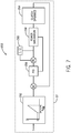
- FIG. 7 is a block diagram 250 of one embodiment of the disclosed incremental PID controller 52.
- the gear ratio is zero when there is no engagement, the drive shaft 16 is rotating, and the PTO shaft 20 is not rotating.
- the target normalized gear ratio across the PTO clutch 60 for full engagement is 1.
- the gear ratio across the PTO clutch 60 may be determined by the controller 52 as a function of the commanded gear ratio as time t ranges from zero to tagg, where tagg, is the time of engagement. This is illustrated by block 252 of FIG. 7 .
- the value tagg may be 2 seconds.
- the value tagg may be 1.5 seconds.
- the value tagg may be 1 second.
- PTO clutch 60 dynamics (e.g., the rotational speed of the shaft before and/or after the clutch) may be determined in block 254.
- the PTO clutch 60 dynamics are combined with the time of engagement tagg and input to the PID controller (block 256).
- the power saturation (e.g., the power output of the engine 12 as a ratio of the power rating of the clutch) may be determined in block 258 and fed back to the PID controller (block 256).
- the PTO controller 52 may stop providing current, terminate the engagement, and generate an error. This will be discussed in more detail below, with regard to FIGS. 9-12 .
- the PID controller (block 256) outputs an incremental torque (PID(n gear )), which may be added to the current measured or determined torque T k , or parameter indicative of torque (block 260), to generate the commanded torque T k+1, as discussed above with regard to Equation 4.
- the commanded torque T k+1 may correspond to a commanded pressure in the cylinder 106 and/or a current of the command signal.
- the controller 52 may determine the current of the control signal to the solenoid 100 to achieve the commanded cylinder 106 pressure. Accordingly, the controller 52 may output the calculated current to the solenoid 100 as part of the control signal.
- the controller 52 may also include a maximum engagement time, after which the attempted engagement is ceased and an error is generated if there is no engagement.
- the maximum engagement time t lockup may be set at 15 seconds. In other embodiments, t lockup may be 5 seconds, 10 seconds, 20 seconds, 25 seconds, 30 seconds, or any other time period. If time t reaches 15 seconds and there is no engagement, the attempted engagement is ceased and an error is generated. In other embodiments, the maximum engagement time t lockup may be set at 5, 6, 7, 8, 9, 10, 11, 12, 13, 14, 15, 16, 17, 18, 19, 20, 21, 22, 23, 24, 25, 26, 27, 28, 29, or 30 seconds, or any other desired time.
- the controller 52 proceeds to the ramp mode.
- the threshold time period is 0.1 seconds, in other embodiments, the threshold time period could be set at 0.01 seconds, 0.05 seconds, 0.2 seconds, 0.3 seconds, 0.5 seconds, 0.6 seconds, or any other value.
- the ramp mode Z4 utilizes an open loop to increase the PTO clutch 60 to the maximum torque, maximum current, and/or maximum cylinder 106 pressure in 1 second, for example.
- the ramp mode time period may be 0.5 seconds, 0.75 seconds, 1.25 seconds, 1.5 seconds, 1.75 seconds, 2 seconds, 2.5 seconds, 3 seconds, 4 seconds, or any other value.
- the controller proceeds to the disengage mode and disengages the clutch.
- the controller reduces the current to zero, the clutch is disengaged, and the PTO shaft 20 is coupled to, and driven by, the engine 12. If at any point during operation, the command from the controller 52 is to disconnect the load 24, the controller 52 also proceeds to disengage mode. Upon locking up of the PTO clutch, the PTO shaft 20 will be driven by the engine 12.
- FIG. 8 is a flow chart of an embodiment of a process 300 for controlling PTO clutch 60 engagement.
- the process 300 may be stored in a non-transitory computer readable medium such as the memory component 66, (e.g., in the form of code) and executable by the processor 64.
- the instructions are received to engage the PTO clutch 60.
- the instructions may also include information regarding the type of engagement (e.g., high aggressive, medium aggressive, or low aggressive type engagement).
- the instructions may come from the operator of the tractor 10 (e.g., via the operator interface 54 or a PTO gear selection interface). In other embodiments, the instructions may be from the controller 52.
- the cylinder 106 is filled until the commanded cylinder pressure is reached.
- the controller 52 sends a control signal to the solenoid 100, which operates the valve 102, allowing fluid flow between the reservoir 104 and the cylinder 106.
- the pressure in the cylinder 106 may act on the piston 108, which actuates the PTO clutch 60.
- PTO clutch 60 actuation via the solenoid 100 and the valve 102 other techniques of PTO clutch 60 actuation may be utilized.
- This mode of operation may be referred to as pre-fill mode.
- the pressure in the cylinder 106 is gradually increased. This mode may be referred to generally as fill mode.
- Fill mode may include two submodes: the gentle increment submode and the low energy shock submode.
- the gentle increment submode the pressure in the cylinder 106 is gradually (e.g., linearly) increased.
- low energy shock mode the pressure in the cylinder 106 continues to increase, but at a slower rate than in the gentle increment submode.
- the PTO shaft 20 speed may be monitored. If the PTO shaft 20 speed is zero, near zero, or below a threshold value (decision 308), pressure in the cylinder 106 continues to increase in fill mode (block 306). If the PTO shaft 20 speed is above zero, or above a threshold value, the process 300 proceeds to block 310.
- the pressure in the cylinder 106 is increased according to the incremental PID control loop.
- This mode of operation may be referred to as modulation mode.
- the incremental PID control loop was shown and described with regard to FIG. 7 .
- PID control logic is used to determine a torque increment, which is added to the measured torque T k (or determined from a measured parameter indicative or torque, such as shaft speed, shaft acceleration, cylinder pressure, etc.) to determine a commanded torque T k+1 .
- the aggressiveness of the engagement (e.g., high aggressive, medium aggressive, low aggressive) is considered in the PID coefficients of the feedback loop, where more aggressiveness may result in higher gains.
- a limitation may be placed on commanded torque T k+1 according to the maximum available power from the engine 12 and the maximum energy rating of the PTO clutch 60.
- the maximum commanded torque may be based on the power output of the engine. In other embodiments, the maximum commanded torque may be based on the energy rating of the PTO clutch 60.
- a maximum PTO shaft 20 acceleration or maximum PTO shaft 20 velocity rating may be considered.
- the power for PTO clutch 60 engagement is compared to the power output of the engine 12. If the power for engagement is greater than the engine 12 output, then the time of engagement is lengthened (block 314) and the process 300 returns to block 310. If the power for engagement does not exceed the power output of the engine12, the process 300 proceeds to decision 316.
- the energy absorbed by the PTO clutch 60 is compared to the maximum energy rating of the PTO clutch 60. If the energy absorbed by the PTO clutch 60 during engagement exceeds the energy rating of the PTO clutch 60, engagement is ceased (block 318). This will be discussed in more detail with regard to FIGS. 9-12 . If the energy absorbed by the PTO clutch 60 does not exceed the energy rating of the PTO clutch 60, the process 300 proceeds to decision 320.
- the gear ratio across the PTO clutch 60 is calculated and compared to a threshold value.
- the gear ratio across the clutch may be normalized such that it ranges from zero (no engagement) to 1 (full engagement).
- the threshold value is about 0.92. However, other values may be possible. If the gear ratio across the PTO clutch 60 is less than the threshold value, the process 300 returns to block 310 and stays in modulation mode. If the gear ratio across the PTO clutch 60 is greater than the threshold value (e.g., 0.92) for a over a threshold period of time (e.g., 0.1 second), the process 300 proceeds to block 322.
- the controller 52 utilizes an open loop to increase the control signal to the maximum current (which corresponds to the maximum pressure in the cylinder 106) in a given period of time (e.g., 1 second). This may be referred to as ramp mode (block 326).
- the clutch is locked up. This may be referred to as lock up mode.
- lock up mode the PTO shaft 20 is driven by the engine 12.
- FIGS. 9-12 are various graphs illustrating three attempted engagements, each utilizing one of the three different aggressiveness types (e.g., low, medium, and high).
- FIG. 9 is a graph 400 of control signal current for a low aggressive engagement, a medium aggressive engagement, and a high aggressive engagement.
- the x-axis 402 represents time.
- the y-axis 404 represents the current of the control signal output by the controller 52.
- Line 406 is the current of the control signal output by the controller 52 in the low aggressive engagement.
- Line 408 is the current of the control signal output by the controller 52 in the medium aggressive engagement.
- Line 410 is the current of the control signal output by the controller 52 in the high aggressive engagement.
- the aggressiveness type (e.g., low, medium, or high) is factored into the incremental PID control logic.
- the currents of the three control signals 406, 408, 410 are the same or similar in the pre-fill mode Z 1 , as the current steps up and the pressure in the cylinder is increased. As discussed above with regard to FIGS. 4 and 5 , the current of the control signal corresponds to a commanded cylinder 106 pressure.
- the currents of the control signals 406, 408, 410 continue to track one another through the fill mode Z2, which includes the gentle increment Z 21 submode and the low energy shocking Z 22 submode. As discussed with regard to FIG. 4 , during fill mode Z2, the commanded cylinder 106 pressure, which is indicated by the current of the control signal, gradually increases. In the modulation mode Z3, beginning at point 412, the three control signals 406, 408, 410 diverge from one another.
- the current increases between points 412 and 414.
- the rate at which the current of the high aggressive type engagement control signal 410 increases slows down. This may be for a variety of reasons. For example, the rotational speed of the engine 12 may drop, causing the controller (which applies the incremental PID feedback control loop illustrated and discussed with regard to FIG. 7 ) to reduce the incremental torque or stop incrementing all together in order to extend the engagement time.
- the controller which applies the incremental PID feedback control loop illustrated and discussed with regard to FIG. 7
- the current of the high aggressive type engagement control signal 410 continues to increase, but at a much slower rate than it did between points 412 and 414.
- the current of the control signal may be entirely flat (e.g., incremental torque is zero) for a period of time during engagement.
- the current of the high aggressive type engagement control signal 410 ramps up again. This may be because the engine 12 has recovered and the rotational speed of the engine has increased, or for some other reason.
- the current of the high aggressive type engagement control signal 410 transitions from the modulation mode Z3 to the ramp mode Z4 and increases to a maximum current (point 420) over a given period of time.
- the current gradually increases between points 412 and 422 over a longer period of time than in the high aggressive type engagement 410. At point 422, the current increases at a faster rate than before. At point 424, the current of the medium aggressive type engagement control signal 408 transitions from the modulation mode Z3 to the ramp mode Z4 and increases to a maximum current over a given period of time.
- the current gradually increases between points 412 and 426 over a longer period of time than in the high aggressive type engagement 410 or the medium aggressive type engagement 408.
- the current falls to zero, indicating the controller 25 has ceased the engagement attempt.
- the engagement attempt was ceased because the energy absorbed by the PTO clutch 60 approached or exceeded the maximum energy rating of the PTO clutch 60.
- the current of the control signal goes to zero and an error message may be generated and displayed to the operator (e.g., via the operator interface 54).
- FIG. 10 is a graph 500 of the energy absorbed by the PTO clutch 60 during the low aggressive type engagement (line 502), the medium aggressive type engagement (line 504), and the high aggressive type engagement (line 506).
- the x-axis 508 represents time.
- the y-axis 510 represents energy absorbed by the PTO clutch 60.
- Line 512 represents the maximum energy rating of the PTO clutch 60.
- the medium aggressive type engagement 504 and the high aggressive type engagement 504 are completed without reaching the energy rating 512 of the PTO clutch 60.
- the low aggressive type engagement 502 reaches the maximum energy rating 512 of the PTO clutch 60 before the engagement is completed.
- the controller 52 upon reaching the maximum energy rating 512 of the PTO clutch 60, the controller 52 ceases engagement and the current of the control signal falls to zero.
- FIG. 11 is a graph of the rotational shaft speed before and after the PTO clutch 60 during each of the low aggressive type engagement, the medium aggressive type engagement, and the high aggressive type engagement.
- the x-axis 602 represents time and the y-axis 604 represents rotational speed.
- Line 606 represents the rotational speed of the shaft before the PTO clutch 60, which in some embodiments may correspond to the rotational speed of the drive shaft 16, for the low aggressive type engagement.
- Line 608 represents the shaft speed after the PTO clutch 60 for the low aggressive type engagement.
- the rotational speed 606 of the shaft before the PTO clutch 60 begins to fall.
- the rotational speed 606 of the shaft before the PTO clutch 60 falls steadily as the rotational speed 608 of the shaft after the PTO clutch 60 rises steadily.
- the energy absorbed by the PTO clutch 60 exceeded the maximum energy rating of the PTO clutch 60 and the engagement attempted was ceased.
- the ceased engagement is evidenced in graph by the gap 612 between the rotational shaft speed 606 before the PTO clutch 60 and the rotational shaft speed 608 after the PTO clutch.
- the gap 612 indicates that the attempted engagement was ceased before the rotational shaft speed 608 after the PTO clutch 60 could be brought up to match the rotational shaft speed 606 after the PTO clutch 60.
- Line 614 represents the rotational speed of the shaft before the PTO clutch 60 for the medium aggressive type engagement.
- Line 616 represents the shaft speed after the PTO clutch 60 for the medium aggressive type engagement.
- the rotational speed 606 of the shaft before the PTO clutch 60 begins to fall.
- the rotational speed 614 of the shaft before the PTO clutch 60 falls steadily as the rotational speed 616 of the shaft after the PTO clutch 60 rises steadily. Because the engagement type is a medium aggressive type engagement, the rotational speed 614 of the shaft before the PTO clutch 60 falls at a faster rate than in the low aggressive type engagement.
- the engagement type is a medium aggressive type engagement
- the rotational speed 616 of the shaft after the PTO clutch 60 rises at a faster rate than in the low aggressive type engagement.
- the rotational speed 616 of the shaft after the PTO clutch 60 matches the rotational speed 614 of the shaft before the PTO clutch 60.
- the rotational speed 616 of the shaft after the PTO clutch 60 and the rotational speed 614 of the shaft before the PTO clutch 60 then increase together as the engine 12 recovers.
- the medium aggressive type engagement is completed and the controller proceeds to the lock up mode Z5.
- Line 620 represents the rotational speed of the shaft before the PTO clutch 60 for the high aggressive type engagement.
- Line 622 represents the shaft speed after the PTO clutch 60 for the high aggressive type engagement.
- the rotational speed 606 of the shaft before the PTO clutch 60 begins to fall.
- the rotational speed 614 of the shaft before the PTO clutch 60 falls steadily as the rotational speed 616 of the shaft after the PTO clutch 60 rises steadily.
- the engagement type is a high aggressive type engagement, the rotational speed 620 of the shaft before the PTO clutch 60 falls at a faster rate than in the low aggressive type engagement or the medium type engagement.
- the rotational speed 622 of the shaft after the PTO clutch 60 rises at a faster rate than in the low aggressive type engagement or the medium type engagement.
- the rotational speed 622 of the shaft after the PTO clutch 60 matches the rotational speed 620 of the shaft before the PTO clutch 60. Because the engagement type is a high aggressive type engagement, point 624 occurs at an earlier time, but a lower rotational speed than the corresponding point 618 for the medium type engagement.
- the rotational speed 622 of the shaft after the PTO clutch 60 and the rotational speed 620 of the shaft before the PTO clutch 60 then increase together as the engine 12 recovers.
- the high aggressive type engagement is completed and the controller proceeds to the lock up mode Z5.
- FIG. 12 is a graph of the rotational speed of the engine 12 over time during each of the low aggressive type engagement (line 702), the medium aggressive type engagement (line 704), and the high aggressive type engagement (line 706).
- the x-axis represents time and the y-axis 710 represents the rotational speed of the engine 12.
- the rotational speed of the engine 12 may correspond to the rotational speed of the drive shaft 16. Specifically, when the engine 12 is driving the drive shaft 16, the rotational speed of the drive shaft 16 may be determined by multiplying the rotational speed of the engine 12 by the gear ratio of the engine transmission 58. As with the rotational shaft speeds 606, 614, 620 before the PTO clutch discussed with regard to FIG.
- the rotational speed of the engine 12 falls at a faster rate than in the low aggressive engagement 702.
- the rotational shaft speed after the PTO clutch 60 matches the rotational shaft speed before the PTO clutch 60.
- the engine 12 recovers as the rotational shaft speed after the PTO clutch 60 and the rotational shaft speed 614 before the PTO clutch 60 then increase together.
- the medium aggressive type engagement is completed and the controller proceeds to the lock up mode Z5.
- the rotational speed of the engine 12 falls at a faster rate than in either the low aggressive engagement 702 or the medium aggressive engagement 704.
- the rotational shaft speed after the PTO clutch 60 matches the rotational shaft speed before the PTO clutch 60.
- the engine 12 recovers as the rotational shaft speed after the PTO clutch 60 and the rotational shaft speed 614 before the PTO clutch 60 then increase together.
- the high aggressive type engagement is completed and the controller 52 proceeds to the lock up mode Z5.
- the disclosed techniques include control of a PTO clutch 60 during engagement utilizing an incremental PID feedback control loop 250.
- the incremental PID feedback control loop 250 uses PID control logic to determine an incremental torque. The sum of the incremental torque and the measured or determined torque equal the commanded torque.
- the incremental PID feedback control loop 250 may consider the power output of the engine 12 and the energy absorption rating of the PTO clutch when determining the incremental toque.
- the incremental PID feedback control loop 250 may also consider one of multiple different aggressiveness types, wherein the aggressiveness type of the engagement corresponds to the elapsed time during engagement.
- Incremental PID control of the PTO clutch 60 may reduce or eliminate engine 12 stalls during engagement and may increase the life of the PTO clutch 60 by maintaining the energy absorbed by the PTO clutch 60 below an energy rating.
Landscapes
- Engineering & Computer Science (AREA)
- Mechanical Engineering (AREA)
- General Engineering & Computer Science (AREA)
- Transportation (AREA)
- Chemical & Material Sciences (AREA)
- Combustion & Propulsion (AREA)
- Physics & Mathematics (AREA)
- Fluid Mechanics (AREA)
- Automation & Control Theory (AREA)
- Hydraulic Clutches, Magnetic Clutches, Fluid Clutches, And Fluid Joints (AREA)
Abstract
Description
- This disclosure relates generally to power take-offs (PTOs), and more specifically to controlling the clutch of a PTO.
- Power take-offs are typically used in vehicles, such as tractors and trucks, to provide power from an engine of the vehicle to a machine (e.g., an agricultural implement) that may be attached to the vehicle or towed behind the vehicle. For example, in an agricultural application, a tractor may tow an implement (e.g., a tiller, a seeder, a harvester, etc.) over a field in order to perform an agricultural task. A PTO may be coupled to the engine of the vehicle (e.g., via a drive shaft) to provide power to the implement. The PTO may include a PTO clutch to couple and decouple a PTO shaft and the drive shaft. A time-based PTO clutch engagement modulation may result in the engine stalling if the power output of the engine is insufficient to complete the desired engagement. Similarly, if the energy absorbed by the PTO clutch during the desired engagement exceeds the energy rating of the PTO clutch, the lifespan of the clutch may be reduced.
- Certain embodiments commensurate in scope with the originally claimed subject matter are summarized below. These embodiments are not intended to limit the scope of the claimed subject matter, but rather these embodiments are intended only to provide a brief summary of possible forms of the disclosure. Indeed, the disclosure may encompass a variety of forms that may be similar to or different from the embodiments set forth below.
- In one embodiment, a method includes measuring a parameter indicative of a measured torque in a PTO clutch, determining an incremental torque based at least in part on proportional-integral-derivative (PID) control logic, determining a command torque, wherein the command torque is a sum of the measured torque and the incremental torque, generating a control signal, wherein a current of the control signal corresponds to the command torque and a pressure in a cylinder of the PTO clutch, providing the control signal to the PTO clutch, reducing the incremental torque if an engagement power exceeds an engine power output, and ceasing engagement if an energy absorbed by the clutch exceeds an energy rating of the PTO clutch.
- In a second embodiment, a non-transitory computer readable medium includes executable instructions that when executed cause a processor to determine an incremental torque based at least in part on proportional-integral-derivative (PID) control logic, determine a command torque, wherein the command torque is a sum of a current torque and the incremental torque, wherein the current torque is determined based on a measure parameter indicative of the current torque, generate a control signal, wherein the current of the control signal corresponds to the command torque and a pressure in a cylinder of the PTO clutch, provide the control signal to the PTO clutch, reduce the incremental torque if an engagement power approaches or exceeds an engine power output, and cease engagement if an energy absorbed by the clutch exceeds an energy rating of the PTO clutch.
- In a third embodiment, a system includes a PTO clutch configured to couple and decouple a PTO shaft and a drive shaft and a controller. The PTO clutch includes a cylinder, a piston disposed within the cylinder, a valve fluidly coupled to the cylinder and configured to restrict or allow fluid flow between the cylinder and a fluid reservoir, and a solenoid coupled to the valve and configured to control a position of the valve. The controller is in communication with the solenoid, and is configured to receive a current torque in a PTO clutch, wherein the current torque is based on a measured parameter indicative of the current torque in the PTO clutch, determine an incremental torque based at least in part on PID control logic, determine a command torque, wherein the command torque is a sum of a current torque and the incremental torque, generate a control signal, wherein a current of the control signal corresponds to the command torque and a pressure in a cylinder of the PTO clutch, provide the control signal to the solenoid, reduce the incremental torque if an engagement power approaches or exceeds an engine power output, and cease engagement if an energy absorbed by the clutch exceeds an energy rating of the PTO clutch.
- These and other features, aspects, and advantages of the present disclosure will become better understood when the following detailed description is read with reference to the accompanying drawings in which like characters represent like parts throughout the drawings, wherein:
-
FIG. 1 is a schematic of a tractor, in accordance with an embodiment; -
FIG. 2 is a schematic of a drive system of the tractor shown inFIG. 1 , in accordance with an embodiment; -
FIG. 3 is a schematic of an embodiment of the PTO clutch shown inFIG. 2 ; -
FIG. 4 is a graph of a commanded pressure in the PTO clutch cylinder ofFIG, 3 during an engagement, in accordance with an embodiment; -
FIG. 5 is a graph of the relationship between the commanded pressure in the PTO clutch cylinder and the current of the control signal provided by the controller, in accordance with an embodiment; -
FIG. 6 is a graph of engine torque versus rotational speed of the engine, in accordance with an embodiment; -
FIG. 7 is a block diagram of an embodiment of an incremental PID controller; -
FIG. 8 is a flow chart of an embodiment of a process for controlling PTO engagement, in accordance with an embodiment; -
FIG. 9 is a graph of a control signal current for a low aggressive engagement, a medium aggressive engagement, and a high aggressive engagement, in accordance with an embodiment; -
FIG. 10 is a graph of energy absorbed by the PTO clutch during the low aggressive type engagement, the medium aggressive type engagement, and the high aggressive type engagement, in accordance with an embodiment; -
FIG. 11 is a graph of the rotational shaft speed before and after the PTO clutch during each of the low aggressive type engagement, the medium aggressive type engagement, and the high aggressive type engagement, in accordance with an embodiment; and -
FIG. 12 is a graph of the rotational speed of the engine over time during each of the low aggressive type engagement, the medium aggressive type engagement, and the high aggressive type engagement, in accordance with an embodiment. - One or more specific embodiments of the present disclosure will be described below. In an effort to provide a concise description of these embodiments, all features of an actual implementation may not be described in the specification. It should be appreciated that in the development of any such actual implementation, as in any engineering or design project, numerous implementation-specific decisions must be made to achieve the developers' specific goals, such as compliance with system-related and business-related constraints, which may vary from one implementation to another. Moreover, it should be appreciated that such a development effort might be complex and time consuming, but would nevertheless be a routine undertaking of design, fabrication, and manufacture for those of ordinary skill having the benefit of this disclosure.
- When introducing elements of various embodiments of the present disclosure, the articles "a," "an," "the," and "said" are intended to mean that there are one or more of the elements. The terms "comprising," "including," and "having" are intended to be inclusive and mean that there may be additional elements other than the listed elements. Any examples of operating parameters and/or environmental conditions are not exclusive of other parameters/conditions of the disclosed embodiments.
- The presently disclosed embodiments include techniques for controlling a power takeoff (PTO) clutch utilizing an incremental PID feedback control loop that considers a power output of an engine and an energy absorbed by the PTO clutch during engagement. Incremental PID control of the PTO clutch may reduce or eliminate engine stalls during engagement and may increase the life of the PTO clutch by maintaining the energy absorbed by the PTO clutch below an energy rating.
-
FIG. 1 is a diagram of an off-road vehicle (e.g., a tractor 10), including anengine 12, anengine transmission assembly 14, adrive shaft 16, a power takeoff (PTO)transmission assembly 18, and aPTO shaft 20, in accordance with an embodiment of the present disclosure. Theengine transmission assembly 14 is coupled to theengine 12 to transfer power from theengine 12 to thedrive shaft 16, which powerswheels 22 of thetractor 10. ThePTO transmission assembly 18 is coupled to the engine 12 (e.g., via drive shaft 16) and thePTO shaft 20 such that theengine 12 drives thePTO shaft 20. As will be described below, the PTO transmission assembly may include a PTO clutch that is controlled according to an incremental PID feedback control loop. In some implementations, thetractor 10 may be an autonomous tractor, such that thetractor 10 may be driven without operator input or include automated control, but with an operator present (e.g., supervised autonomy). Thetractor 10 may be coupled to animplement 24. Theimplement 24 may be a raker, tillage implement, mower, seeder, harvester, or any other implement. Theimplement 24 may be coupled to thePTO shaft 20 such that thePTO shaft 20 powers certain components on theimplement 24. -
FIG. 2 is a schematic of one embodiment of adrive system 50 of thetractor 10 shown inFIG. 1 . In the illustrated embodiment, thedrive system 50 includes theengine 12, theengine transmission assembly 14, thedrive shaft 16, thePTO transmission assembly 18, thePTO shaft 20, acontroller 52, and anoperator interface 54. Other embodiments of thedrive system 50 may include different elements in alternative combinations. - The
engine transmission assembly 14 may include anengine transmission 58. ThePTO transmission assembly 18 may include aPTO clutch 60 and aPTO transmission 62. ThePTO clutch 60 may be a push type clutch, a pull type clutch, a single plate clutch a multiple plate clutch, a wet clutch, a dry clutch, a centrifugal clutch, a belt clutch, a dog clutch, a hydraulic clutch, an electromagnetic clutch, or any other type of clutch. ThePTO clutch 60 may be configured to engage and disengage in order to couple and decouple thePTO shaft 20 from the drive shaft 16 (and the engine 12). When theengine 12 is running, thedrive shaft 16 is rotating, and thePTO transmission 62 andPTO shaft 20 are decoupled from thedrive shaft 16, thePTO clutch 60 may be engaged to bring thePTO transmission 62 andPTO shaft 20 up to speed with thedrive shaft 16. ThePTO clutch 60 may then be locked up to couple thePTO transmission 62 andPTO shaft 20 to theengine 12, such that theengine 12 rotates the PTO shaft 20 (e.g., via the drive shaft 16). ThePTO clutch 60 may be disengaged in in order to enable thePTO shaft 20 to slow down, or so thePTO transmission 62 can change gears. As discussed below, thePTO clutch 60 may be controlled according to an incremental PID feedback control loop. - The
PTO transmission 62 may be a geared transmission or a non-geared transmission, such as a continuously variable transmission. The gear may be selected manually by the user, or automatically via thecontroller 52. ThePTO transmission 62 may have the same number of gears as theengine transmission 58, or a different number of gears. For example, thePTO transmission 62 may have a high gear and a low gear, selectable by the user (e.g., via the operator interface 54). In other embodiments, thePTO transmission 62 may have more than 2 gears. For example, thePTO transmission 62 may have 2, 3, 4, 5, 6, 7, 8, 9, 10, or any other number of gears. - The
controller 52 may include an incremental proportional-integral-derivative (PID) controller for controlling the PTO clutch 60. The specific functionality of thecontroller 52 is described in more detail below. Thecontroller 52 may include aprocessor 64, amemory component 66, andcommunication circuitry 68. Theprocessor 64 may include one or more general-purpose processors, one or more application specific integrated circuits, one or more field programmable gate arrays, or the like. Thememory 66 may be any tangible, non-transitory, computer readable medium that is capable of storing instructions executable by theprocessor 64 and/or data that may be processed by theprocessor 64. In other words, thememory 66 may include volatile memory, such as random access memory, or non-volatile memory, such as hard disk drives, read-only memory, optical disks, flash memory, and the like. Thecommunication circuitry 68 may be configured to receive inputs (e.g., feedback signals, sensor signals, etc.) and transmit outputs (e.g., control signals, command signals, etc.) to the various components of thedrive system 50. - The
operator interface 54 may be disposed inside the tractor 10 (e.g., in a cab of the tractor 10) and be configured to display information for, and receive inputs from, the operator. In the illustrated embodiment, theoperator interface 54 includes aprocessor 70, amemory component 72,communication circuitry 74, adisplay 76, andoperator inputs 78. Theprocessor 70 may include one or more general-purpose processors, one or more application specific integrated circuits, one or more field programmable gate arrays, or the like. Thememory 72 may be any tangible, non-transitory, computer readable medium that is capable of storing instructions executable by theprocessor 70 and/or data that may be processed by theprocessor 70. Thememory 72 may include volatile memory, such as random access memory, or non-volatile memory, such as hard disk drives, read-only memory, optical disks, flash memory, and the like. Thecommunication circuitry 74 may be configured to communicate with the controller 52 (e.g., via thecommunication circuitry 68 of the controller 52). In some embodiments, thecommunication circuitry drive system 50 wirelessly. In some embodiments, theoperator interface 54 and thecontroller 52 may be disposed within the same housing, may shareprocessors memory components communication circuitry controller 52 and theoperator interface 54 may be the same component. Theoperator interface 54 includes thedisplay 76, which may be configured to display information related to thetractor 10 to the operator. Thedisplay 76 may be a screen, an array of LEDs, a series of gauges, a combination thereof, or some other arrangement. Theoperator interface 54 also includes anoperator input 78 that enables a user to input information. Theoperator input 78 may be a keyboard, a series of buttons, a joystick, a mouse, a track pad, etc. In some embodiments, thedisplay 76 and theoperator input 78 may be a single component (e.g., a touchscreen). - Based on inputs received from the
operator interface 54 and one ormore sensors 80 disposed throughout thesystem 50, as well as inputs that may be stored in the memory component 56, thecontroller 52 may output a control signal to one or more of the components within thedrive system 50. Thedrive system 50 has at least onespeed sensor 80 to measure the rotational speed of the PTO shaft (e.g., PTO shaft speed sensor 84). In some embodiments, thedrive system 50 may have aspeed sensor 80 to determine the rotational speed of the engine 12 (e.g., engine speed sensor 86). In some embodiments, theengine 12 may have its own dedicated controller (e.g., ECU 82) that controls the operation of theengine 12. In such embodiments, theECU 82 may be in communication with, or receive instructions from, thecontroller 52 and/or theoperator interface 54. In some embodiments, thecontroller 52 may receive information (e.g.,engine 12 speed) from theECU 82 rather than thesensor 80. Accordingly, theECU 82 may output theengine 12 speed to thecontroller 52. As shown inFIG. 2 , thedrive system 50 may includeother speed sensors 80 disposed at various locations throughout thedrive system 50. -
FIG. 3 is a schematic of the PTO clutch 60. As previously discussed, thecontroller 52 may output a control signal to one or more of the components within thedrive system 50. In the embodiment shown inFIG. 3 , thecontroller 52 outputs a control signal (e.g., a current) to asolenoid 100 within the PTO clutch 60. It should be understood, however, that the use of thesolenoid 100 to actuate control of the PTO clutch 60 is merely an example and that other configurations may be possible. Thesolenoid 100 may actuate avalve 102 between afluid reservoir 104 and acylinder 106. Thecylinder 106 may include apiston 108, upon which the pressure in thecylinder 106 acts to actuate engagement of the PTO clutch 60. The current of the control signal output to thesolenoid 100 may indicate the desired position of the valve 102 (open, closed, partially open, etc.) or commanded pressure in thecylinder 106. The pressure in thecylinder 106 may be indicative of clutch engagement. - PTO clutch 60 engagement is typically controlled using time-based engagement modulation. Time-based engagement modulation may be based on an acceleration of the PTO shaft 20 (shown in
FIG. 1 ) and time. If the load of the implement 24 is too high, the time-based engagement modulation may cause theengine 12 speed (RPM) to drop excessively, or may generate more energy than the PTO clutch 60 is rated to absorb energy during the engagement. Accordingly, thecontroller 52 may utilize the incremental PID feedback control loop to control engagement of the PTO clutch 60 to limit anengine 12 power and an energy absorbed by the PTO clutch 60 during the engagement. Rather than using a time-based engagement modulation, the disclosed techniques considerengine 12 power and energy absorbed by the PTO clutch 60 during engagement in controlling the PTO clutch 60. Controlling PTO clutch 60 engagement using a closed loopincremental PID controller 52 that considersengine 12 power and energy absorbed by the PTO clutch 60 may reduce or eliminateengine 12 speed drop and reduce or eliminate instances in which the energy absorbed by the PTO clutch 60 exceeds the energy rating of the PTO clutch 60. For example, thecontroller 52 may be configured to cease engagement if the estimated energy absorbed by the PTO clutch 60 during the engagement exceeds the energy rating of the PTO clutch 60. The values of the incremental PID gains determine how quickly engagement occurs. The disclosed embodiments include three types of engagement: high aggressive, medium aggressive, and low aggressive. However, it should be understood, that embodiments with different numbers of aggressiveness types are also envisaged. For example, other embodiments may have 1, 2, 3, 4, 5, 6, 7, 8, 9, 10, or more aggressiveness types. In other embodiments, the various aggressiveness types may not be a series of discrete values, but a continuous spectrum of values. - The incremental PID control logic used by the
controller 52 to control the PTO clutch 60 engagement in thetractor 10 has five modes, which will be described in more detail below: pre-fill, fill, modulation, ramp to steady, and locking up. The fill mode may include two submodes: gentle increment and low energy shocking.FIG. 4 is agraph 150 of one embodiment of the commanded pressure in the PTO clutch cylinder 106 (communicated via the control signal sent to thesolenoid 100 discussed with regard toFIG. 3 ) versus time in each of the five modes. Ingraph 150, thex-axis 152 represents time and the y-axis 154 represents the commanded pressure in thecylinder 102, as commanded by thecontroller 52 via the control signal.Line 156 represents the commanded pressure in thecylinder 106 over time. The pre-fill mode is represented by Z1, the fill mode is represented by Z21 and Z22 (the gentle increment submode and the low energy shocking submode, respectively), the modulation mode is represented by Z3, the ramp mode is represented by Z4, and the lock up mode is represented by Z5. - If the
PTO shaft 20 speed (e.g., after the PTO transmission 62) is detected (e.g., via the sensor 84) to be zero, the controller enters the pre-fill mode Z1. If thePTO shaft 20 speed (e.g., after the PTO transmission 62) is detected (e.g., via the sensor 84) to be nonzero, the pre-fill mode is skipped and thecontroller 52 proceeds to the modulation mode Z3. - In the pre-fill mode, indicated by Z1 in
FIG. 4 , the control signal sent by thecontroller 52 to thesolenoid 100 instructs thesolenoid 100 to open thevalve 102, allowing fluid (e.g., oil) to flow from thereservoir 104 to thecylinder 106, increasing the pressure in thecylinder 106. Fluid fills the PTOclutch cylinder 106 until the pressure in thecylinder 106 reaches the commanded pressure. Once the pressure in thecylinder 106 reaches the commanded pressure, the controller proceeds to fill mode, indicated by Z21 and Z22 inFIG. 4 . - The fill mode, indicated by Z21 and Z22 in
FIG. 4 , begins with the gentle increment Z21 submode followed by the low energy shock Z22submode, as shown inFIG. 4 . In the gentle increment submode Z21, the controller gradually (e.g., linearly) increases the pressure in thecylinder 106. In low energy shock mode Z22, the controller continues to increase the pressure in thecylinder 106, but at a slower rate than in the gentle increment submode Z21. If at any point during the fill mode, thecontroller 52 determines that thePTO shaft 20 speed is greater than zero, thecontroller 52 proceeds to the modulation mode Z3. - In modulation mode, indicated by Z3 in
FIG. 4 , the pressure in the cylinder is increased and the speed of thePTO shaft 20 are increased. When the PTO clutch 60 is fully locked up, the gear ratio across the PTO clutch 60 (e.g., the rotational speed of the shaft, in RPM, after the clutch divided by the rotational speed of the shaft, in RPM before the shaft) is zero. When the PTO clutch 60 is fully engaged, shaft before the PTO clutch 60 rotates at the same speed as the shaft after the PTO clutch 60. Accordingly, when the PTO clutch 60 is fully engaged, the gear ratio across the PTO clutch 60 (e.g., the rotational speed of the shaft, in RPM, after the clutch divided by the rotational speed of the shaft, in RPM before the shaft) is 1. During modulation mode, as the rotational speed of thePTO shaft 20 increases, the gear ratio across the PTO clutch 60 also increases. When the gear ratio across the PTO clutch 60 reaches a threshold value (e.g., 0.92), thecontroller 52 proceeds to the ramp mode. In the present embodiment, the threshold gear ratio is 0.92, however other values may be possible. For example, the threshold gear ratio may be 0.7, 0.75, 0.8, 0.85, 0.87, 0.89, 0.9, 0.91, 0.92, 0.93, 0.94, 0.95, 0.96, 0.97, 0.98, 0.99, or any other value. In the ramp mode, indicated by Z4 inFIG. 4 , thecontroller 52 utilizes an open loop to increase the control signal to the maximum current in a given period of time (e.g., 1 second). The modulation and ramp modes will be discussed in more detail below. - During engagement, the PTO clutch 60 applies a torque T to the load (e.g., the implement 24, via the PTO shaft 20) defined by:

cylinder 106 pressure, A is the engagement surface area,is the relative angular velocity or slip, and Req is effective torque radius, which may be defined by:

cylinder 106 is defined by:
FIG. 5. FIG. 5 is agraph 180 of the relationship between the commanded pressure in thecylinder 106 and the current of the control signal provided by thecontroller 52. Thex-axis 182 represents the current of the control signal from thecontroller 52. The y-axis 184 represents the commanded pressure in thecylinder 106. As previously discussed, the current is provided to thesolenoid 100 via the control signal from thecontroller 52. The controller may provide the current that corresponds to the commandedcylinder 106 pressure. In some embodiments, the relationship between current and the commanded pressure illustrated inFIG. 5 may also be represented by a lookup table. Thesolenoid 100 operates thevalve 102, which allows or restricts fluid (e.g., oil) flow between thereservoir 104 and thecylinder 106. Thecylinder 106 may include thepiston 108, which may actuate (e.g., engage or disengage) the PTO clutch 60. The pressure in thecylinder 106 acts on thepiston 108, affecting the position of thepiston 108 and the engagement of the PTO clutch 60. - The
controller 52 may receive thePTO shaft 20 speed from the PTO shaft speed sensor 84, and theengine 12 speed from the engine speed sensor 86, or from theECU 82. An instantaneous PTO clutch 80 gear ratio is calculated by dividing the shaft speed just after the PTO clutch 60 by the shaft speed just before the PTO clutch 60. The shaft speed just before the PTO clutch 60 may be determined by multiplying theengine 12 speed (e.g., as received from theECU 82 or the engine speed sensor 86) by the commandedengine transmission 58 gear ratio. In some embodiments, there may be a sensor 80 (shown inFIG. 2 ) to measure the speed of thedrive shaft 16. The shaft speed just after the PTO clutch 60 may be determined by multiplying thePTO shaft 20 speed (e.g., as received from PTO shaft speed sensor 84) by the commandedPTO transmission 62 gear ratio. In some embodiments, the shaft speed before and after the PTO clutch 60 may be determined in other ways based uponavailable sensors 80 disposed throughout the system and other known values within the drive system 50 (e.g., commanded gear ratios,engine 12 speed, etc.). Accordingly, the gear ratio across the PTO clutch 60 may be determined by dividing the calculated shaft speed just after the PTO clutch 60 by the calculated shaft speed just before the PTO clutch. In other embodiments, the instantaneous clutch gear ratio may be determined by taking a ratio of engine speed to PTO shaft speed. Using the shaft speed just before the PTO clutch 60 and the shaft speed just after the PTO clutch 60, the PTO clutch 60 gear ratio may be determined. The PTO clutch 60 gear ratio ranges between 0 (no engagement) and 1 (fully engaged). - In the modulation mode Z3, the
controller 52 increments the torque T using PID control law. A PID controller continuously calculates an error value as the difference between the measured process variable and a desired setpoint. The presently disclosedcontroller 52 is an incremental PID controller in that PID control law is used to determine a torque increment based on a measured or determined torque Tk (e.g., based on a parameter indicative of the torque, for example shaft speed, shaft acceleration, cylinder pressure, etc.). The commanded torque Tk+1 is the sum of the current (e.g., measured) torque Tk and the calculated torque increment. In the instant embodiment, the commanded torque Tk+1 may be defined by:
controller 52, where more aggressiveness may result in higher gains. - In some embodiments, a limitation may be placed on commanded torque Tk+1 according to the maximum available power from the
engine 12 and the energy rating of the PTO clutch 60. Additionally, to control how much power is transferred from theengine 12 to the PTO clutch 60, a maximum acceleration or maximum velocity rating may be considered. For example, in a highly aggressive type engagement, the engagement duration may be 2 seconds. For a medium aggressive type engagement, the engagement duration may be 1.5 seconds. For low aggressive type engagement, the engagement duration may be 1 second. In other embodiments, the engagement duration for a high aggressive type engagement, a medium aggressive type engagement, or a low aggressive type engagement may be 0.1 seconds, 0.2 second, 0.3 seconds, 0.4 seconds, 0.5 seconds, 0.7 seconds, 1 second, 1.25 seconds, 1.5 seconds, 1.75 seconds, 2 seconds, 2.5 seconds, 3 seconds, 3.5 seconds, 4.0 seconds, 4.5 seconds, 5 seconds, or any other value. However, it should be understood that these values are merely exemplary and that other values are possible. - The
engine 12 speed may also be considered during PTO clutch 60 engagement.FIG. 6 is agraph 200 ofengine 12 torque versus the rotational speed of theengine 12. The x-axis represents the rotational speed of theengine 12. The y-axis represents theengine 12 torque. If theengine 12 is rotating at a speed between a first speed (e.g.,line 208 about 1500 RPM) or more, theengine 12 is considered stable because an increase in the engine's 12 load will reduce the engine's 12 rotational speed, but theengine 12 will likely recover. If theengine 12 is rotating between the first speed (e.g.,line 208 about 1500 RPM) and a second speed (e.g.,line 210 about 2100 RPM), reducing the rotational speed of theengine 12 may increase the available torque of theengine 12. In this case, theengine 12 will likely recover to balance the load. Because theengine 12 can recover, the controller does not limit the commanded torque, as it is within the engine's 12 power. - If the
engine 12 is spinning at a speed below the first speed (e.g.,line 208 about 1500 RPM), theengine 12 is considered unstable because an increase in the engine load will reduce the engine speed, and theengine 12 will be unlikely to recover. If theengine 12 is spinning below the first speed (e.g.,line 208 about 1500 RPM), reducing the rotational speed of theengine 12 may lead to a reduction of theavailable engine 12 torque. Reduction of available engine speed and torque may stall the engine 12 (e.g., make the engine stop rotating). In order to avoid stalling theengine 12, a PTOincremental PID controller 52 limitation on commanded torque may be determined using a lookup table or a graph (similar to thegraph 200 shown inFIG. 6 ). The lookup table or graph may provide a maximum torque rating as a function of theengine 12 RPM. This limitation may reduce or eliminateengine 12 stall during PTO engagement with high load. -
FIG. 7 is a block diagram 250 of one embodiment of the disclosedincremental PID controller 52. The gear ratio is zero when there is no engagement, thedrive shaft 16 is rotating, and thePTO shaft 20 is not rotating. The target normalized gear ratio across the PTO clutch 60 for full engagement is 1. The gear ratio across the PTO clutch 60 may be determined by thecontroller 52 as a function of the commanded gear ratio as time t ranges from zero to tagg, where tagg, is the time of engagement. This is illustrated byblock 252 ofFIG. 7 . For the highly aggressive type engagement, the value tagg may be 2 seconds. For medium aggressive type engagement, the value tagg may be 1.5 seconds. For low aggressive type engagement, the value tagg may be 1 second. - PTO clutch 60 dynamics (e.g., the rotational speed of the shaft before and/or after the clutch) may be determined in
block 254. The PTO clutch 60 dynamics are combined with the time of engagement tagg and input to the PID controller (block 256). The power saturation (e.g., the power output of theengine 12 as a ratio of the power rating of the clutch) may be determined inblock 258 and fed back to the PID controller (block 256). - Based on the inputs, the PID controller (block 256) may determine energy absorbed by the PTO clutch 60 by integrating power dissipation, defined by:

- If the energy absorbed by the PTO clutch 60 is more than the maximum energy rating of the clutch, the
PTO controller 52 may stop providing current, terminate the engagement, and generate an error. This will be discussed in more detail below, with regard toFIGS. 9-12 . - The PID controller (block 256) outputs an incremental torque (PID(ngear)), which may be added to the current measured or determined torque Tk, or parameter indicative of torque (block 260), to generate the commanded torque Tk+1, as discussed above with regard to Equation 4. The commanded torque Tk+1 may correspond to a commanded pressure in the
cylinder 106 and/or a current of the command signal. Using an equation or a look-up table, thecontroller 52 may determine the current of the control signal to thesolenoid 100 to achieve the commandedcylinder 106 pressure. Accordingly, thecontroller 52 may output the calculated current to thesolenoid 100 as part of the control signal. - The
controller 52 may also include a maximum engagement time, after which the attempted engagement is ceased and an error is generated if there is no engagement. For example, in some embodiments, the maximum engagement time tlockup may be set at 15 seconds. In other embodiments, tlockup may be 5 seconds, 10 seconds, 20 seconds, 25 seconds, 30 seconds, or any other time period. If time t reaches 15 seconds and there is no engagement, the attempted engagement is ceased and an error is generated. In other embodiments, the maximum engagement time tlockup may be set at 5, 6, 7, 8, 9, 10, 11, 12, 13, 14, 15, 16, 17, 18, 19, 20, 21, 22, 23, 24, 25, 26, 27, 28, 29, or 30 seconds, or any other desired time. Once the normalized gear ratio reaches the set threshold value (e.g., 0.92 out of 1) in a time period of less than the maximum engagement time (e.g., t < 15 seconds) for a threshold period of time (e.g., at least 0.1 seconds), thecontroller 52 proceeds to the ramp mode. Though in the present embodiment, the threshold time period is 0.1 seconds, in other embodiments, the threshold time period could be set at 0.01 seconds, 0.05 seconds, 0.2 seconds, 0.3 seconds, 0.5 seconds, 0.6 seconds, or any other value. The ramp mode Z4 utilizes an open loop to increase the PTO clutch 60 to the maximum torque, maximum current, and/ormaximum cylinder 106 pressure in 1 second, for example. However, the ramp mode time period may be 0.5 seconds, 0.75 seconds, 1.25 seconds, 1.5 seconds, 1.75 seconds, 2 seconds, 2.5 seconds, 3 seconds, 4 seconds, or any other value. - Once the maximum torque or maximum current has been reached, or the ramp mode time period (e.g., 1 second) passes, the controller proceeds to the disengage mode and disengages the clutch. In the disengage mode, the controller reduces the current to zero, the clutch is disengaged, and the
PTO shaft 20 is coupled to, and driven by, theengine 12. If at any point during operation, the command from thecontroller 52 is to disconnect theload 24, thecontroller 52 also proceeds to disengage mode. Upon locking up of the PTO clutch, thePTO shaft 20 will be driven by theengine 12. -
FIG. 8 is a flow chart of an embodiment of aprocess 300 for controlling PTO clutch 60 engagement. Theprocess 300 may be stored in a non-transitory computer readable medium such as thememory component 66, (e.g., in the form of code) and executable by theprocessor 64. Inblock 302, the instructions are received to engage the PTO clutch 60. In some embodiments, the instructions may also include information regarding the type of engagement (e.g., high aggressive, medium aggressive, or low aggressive type engagement). In some embodiments, the instructions may come from the operator of the tractor 10 (e.g., via theoperator interface 54 or a PTO gear selection interface). In other embodiments, the instructions may be from thecontroller 52. - In
block 304, thecylinder 106 is filled until the commanded cylinder pressure is reached. In some embodiments, thecontroller 52 sends a control signal to thesolenoid 100, which operates thevalve 102, allowing fluid flow between thereservoir 104 and thecylinder 106. The pressure in thecylinder 106 may act on thepiston 108, which actuates the PTO clutch 60. Though the present embodiments include PTO clutch 60 actuation via thesolenoid 100 and thevalve 102, other techniques of PTO clutch 60 actuation may be utilized. This mode of operation may be referred to as pre-fill mode. Inblock 306, the pressure in thecylinder 106 is gradually increased. This mode may be referred to generally as fill mode. Fill mode may include two submodes: the gentle increment submode and the low energy shock submode. In the gentle increment submode, the pressure in thecylinder 106 is gradually (e.g., linearly) increased. In low energy shock mode, the pressure in thecylinder 106 continues to increase, but at a slower rate than in the gentle increment submode. During the fill mode, thePTO shaft 20 speed may be monitored. If thePTO shaft 20 speed is zero, near zero, or below a threshold value (decision 308), pressure in thecylinder 106 continues to increase in fill mode (block 306). If thePTO shaft 20 speed is above zero, or above a threshold value, theprocess 300 proceeds to block 310. - In
block 310, the pressure in thecylinder 106 is increased according to the incremental PID control loop. This mode of operation may be referred to as modulation mode. The incremental PID control loop was shown and described with regard toFIG. 7 . As previously discussed, PID control logic is used to determine a torque increment, which is added to the measured torque Tk (or determined from a measured parameter indicative or torque, such as shaft speed, shaft acceleration, cylinder pressure, etc.) to determine a commanded torque Tk+1. The aggressiveness of the engagement (e.g., high aggressive, medium aggressive, low aggressive) is considered in the PID coefficients of the feedback loop, where more aggressiveness may result in higher gains. - In some embodiments, a limitation may be placed on commanded torque Tk+1 according to the maximum available power from the
engine 12 and the maximum energy rating of the PTO clutch 60. In some embodiments, the maximum commanded torque may be based on the power output of the engine. In other embodiments, the maximum commanded torque may be based on the energy rating of the PTO clutch 60. Additionally, to control how much power is transferred from theengine 12 to the PTO clutch 60, amaximum PTO shaft 20 acceleration ormaximum PTO shaft 20 velocity rating may be considered. - At
decision 312, the power for PTO clutch 60 engagement is compared to the power output of theengine 12. If the power for engagement is greater than theengine 12 output, then the time of engagement is lengthened (block 314) and theprocess 300 returns to block 310. If the power for engagement does not exceed the power output of the engine12, theprocess 300 proceeds todecision 316. - At
block 316, the energy absorbed by the PTO clutch 60 is compared to the maximum energy rating of the PTO clutch 60. If the energy absorbed by the PTO clutch 60 during engagement exceeds the energy rating of the PTO clutch 60, engagement is ceased (block 318). This will be discussed in more detail with regard toFIGS. 9-12 . If the energy absorbed by the PTO clutch 60 does not exceed the energy rating of the PTO clutch 60, theprocess 300 proceeds todecision 320. - At
decision 320, the gear ratio across the PTO clutch 60 is calculated and compared to a threshold value. The gear ratio across the clutch may be normalized such that it ranges from zero (no engagement) to 1 (full engagement). In the present embodiment, the threshold value is about 0.92. However, other values may be possible. If the gear ratio across the PTO clutch 60 is less than the threshold value, theprocess 300 returns to block 310 and stays in modulation mode. If the gear ratio across the PTO clutch 60 is greater than the threshold value (e.g., 0.92) for a over a threshold period of time (e.g., 0.1 second), theprocess 300 proceeds to block 322. - In
block 322, thecontroller 52 utilizes an open loop to increase the control signal to the maximum current (which corresponds to the maximum pressure in the cylinder 106) in a given period of time (e.g., 1 second). This may be referred to as ramp mode (block 326). - In
block 324, the clutch is locked up. This may be referred to as lock up mode. Following lock up mode, thePTO shaft 20 is driven by theengine 12. -
FIGS. 9-12 are various graphs illustrating three attempted engagements, each utilizing one of the three different aggressiveness types (e.g., low, medium, and high).FIG. 9 is agraph 400 of control signal current for a low aggressive engagement, a medium aggressive engagement, and a high aggressive engagement. Thex-axis 402 represents time. The y-axis 404 represents the current of the control signal output by thecontroller 52.Line 406 is the current of the control signal output by thecontroller 52 in the low aggressive engagement.Line 408 is the current of the control signal output by thecontroller 52 in the medium aggressive engagement.Line 410 is the current of the control signal output by thecontroller 52 in the high aggressive engagement. As previously discussed, the aggressiveness type (e.g., low, medium, or high) is factored into the incremental PID control logic. The currents of the threecontrol signals FIGS. 4 and5 , the current of the control signal corresponds to a commandedcylinder 106 pressure. The currents of the control signals 406, 408, 410 continue to track one another through the fill mode Z2, which includes the gentle increment Z21submode and the low energy shocking Z22submode. As discussed with regard toFIG. 4 , during fill mode Z2, the commandedcylinder 106 pressure, which is indicated by the current of the control signal, gradually increases. In the modulation mode Z3, beginning atpoint 412, the threecontrol signals - For example, for the high aggressive type
engagement control signal 410, the current increases betweenpoints point 414, the rate at which the current of the high aggressive typeengagement control signal 410 increases slows down. This may be for a variety of reasons. For example, the rotational speed of theengine 12 may drop, causing the controller (which applies the incremental PID feedback control loop illustrated and discussed with regard toFIG. 7 ) to reduce the incremental torque or stop incrementing all together in order to extend the engagement time. Betweenpoints engagement control signal 410 continues to increase, but at a much slower rate than it did betweenpoints points engine 12 has recovered and the rotational speed of the engine has increased, or for some other reason. Atpoint 418, the current of the high aggressive type engagement control signal 410 transitions from the modulation mode Z3 to the ramp mode Z4 and increases to a maximum current (point 420) over a given period of time. - For the medium aggressive type
engagement control signal 408, the current gradually increases betweenpoints aggressive type engagement 410. Atpoint 422, the current increases at a faster rate than before. Atpoint 424, the current of the medium aggressive type engagement control signal 408 transitions from the modulation mode Z3 to the ramp mode Z4 and increases to a maximum current over a given period of time. - For the low aggressive type
engagement control signal 406, the current gradually increases betweenpoints aggressive type engagement 410 or the mediumaggressive type engagement 408. Atpoint 426, the current falls to zero, indicating the controller 25 has ceased the engagement attempt. In this specific case, the engagement attempt was ceased because the energy absorbed by the PTO clutch 60 approached or exceeded the maximum energy rating of the PTO clutch 60. When the engagement attempt is ceased, the current of the control signal goes to zero and an error message may be generated and displayed to the operator (e.g., via the operator interface 54). -
FIG. 10 is agraph 500 of the energy absorbed by the PTO clutch 60 during the low aggressive type engagement (line 502), the medium aggressive type engagement (line 504), and the high aggressive type engagement (line 506). Thex-axis 508 represents time. The y-axis 510 represents energy absorbed by the PTO clutch 60.Line 512 represents the maximum energy rating of the PTO clutch 60. As previously discussed, the mediumaggressive type engagement 504 and the highaggressive type engagement 504 are completed without reaching theenergy rating 512 of the PTO clutch 60. However, in the instant case, the lowaggressive type engagement 502 reaches themaximum energy rating 512 of the PTO clutch 60 before the engagement is completed. As discussed above with regard toFIG. 9 , upon reaching themaximum energy rating 512 of the PTO clutch 60, thecontroller 52 ceases engagement and the current of the control signal falls to zero. -
FIG. 11 is a graph of the rotational shaft speed before and after the PTO clutch 60 during each of the low aggressive type engagement, the medium aggressive type engagement, and the high aggressive type engagement. In thegraph 600, thex-axis 602 represents time and the y-axis 604 represents rotational speed.Line 606 represents the rotational speed of the shaft before the PTO clutch 60, which in some embodiments may correspond to the rotational speed of thedrive shaft 16, for the low aggressive type engagement.Line 608 represents the shaft speed after the PTO clutch 60 for the low aggressive type engagement. Atpoint 610, as engagement begins, therotational speed 606 of the shaft before the PTO clutch 60 begins to fall. Over the course of the engagement attempt, therotational speed 606 of the shaft before the PTO clutch 60 falls steadily as therotational speed 608 of the shaft after the PTO clutch 60 rises steadily. As discussed with regard toFIGS. 9 and 10 , in this particular case, the energy absorbed by the PTO clutch 60 exceeded the maximum energy rating of the PTO clutch 60 and the engagement attempted was ceased. The ceased engagement is evidenced in graph by thegap 612 between therotational shaft speed 606 before the PTO clutch 60 and therotational shaft speed 608 after the PTO clutch. Thegap 612 indicates that the attempted engagement was ceased before therotational shaft speed 608 after the PTO clutch 60 could be brought up to match therotational shaft speed 606 after the PTO clutch 60. -
Line 614 represents the rotational speed of the shaft before the PTO clutch 60 for the medium aggressive type engagement.Line 616 represents the shaft speed after the PTO clutch 60 for the medium aggressive type engagement. Atpoint 610, as engagement begins, therotational speed 606 of the shaft before the PTO clutch 60 begins to fall. Over the course of the engagement attempt, therotational speed 614 of the shaft before the PTO clutch 60 falls steadily as therotational speed 616 of the shaft after the PTO clutch 60 rises steadily. Because the engagement type is a medium aggressive type engagement, therotational speed 614 of the shaft before the PTO clutch 60 falls at a faster rate than in the low aggressive type engagement. Similarly, because the engagement type is a medium aggressive type engagement, therotational speed 616 of the shaft after the PTO clutch 60 rises at a faster rate than in the low aggressive type engagement. Atpoint 618, therotational speed 616 of the shaft after the PTO clutch 60 matches therotational speed 614 of the shaft before the PTO clutch 60. Therotational speed 616 of the shaft after the PTO clutch 60 and therotational speed 614 of the shaft before the PTO clutch 60 then increase together as theengine 12 recovers. The medium aggressive type engagement is completed and the controller proceeds to the lock up mode Z5. -
Line 620 represents the rotational speed of the shaft before the PTO clutch 60 for the high aggressive type engagement.Line 622 represents the shaft speed after the PTO clutch 60 for the high aggressive type engagement. Atpoint 610, as engagement begins, therotational speed 606 of the shaft before the PTO clutch 60 begins to fall. Over the course of the engagement attempt, therotational speed 614 of the shaft before the PTO clutch 60 falls steadily as therotational speed 616 of the shaft after the PTO clutch 60 rises steadily. Because the engagement type is a high aggressive type engagement, therotational speed 620 of the shaft before the PTO clutch 60 falls at a faster rate than in the low aggressive type engagement or the medium type engagement. Similarly, because the engagement type is a high aggressive type engagement, therotational speed 622 of the shaft after the PTO clutch 60 rises at a faster rate than in the low aggressive type engagement or the medium type engagement. Atpoint 624, therotational speed 622 of the shaft after the PTO clutch 60 matches therotational speed 620 of the shaft before the PTO clutch 60. Because the engagement type is a high aggressive type engagement,point 624 occurs at an earlier time, but a lower rotational speed than thecorresponding point 618 for the medium type engagement. Therotational speed 622 of the shaft after the PTO clutch 60 and therotational speed 620 of the shaft before the PTO clutch 60 then increase together as theengine 12 recovers. The high aggressive type engagement is completed and the controller proceeds to the lock up mode Z5. -
FIG. 12 is a graph of the rotational speed of theengine 12 over time during each of the low aggressive type engagement (line 702), the medium aggressive type engagement (line 704), and the high aggressive type engagement (line 706). The x-axis represents time and the y-axis 710 represents the rotational speed of theengine 12. The rotational speed of theengine 12 may correspond to the rotational speed of thedrive shaft 16. Specifically, when theengine 12 is driving thedrive shaft 16, the rotational speed of thedrive shaft 16 may be determined by multiplying the rotational speed of theengine 12 by the gear ratio of theengine transmission 58. As with the rotational shaft speeds 606, 614, 620 before the PTO clutch discussed with regard toFIG. 11 above, atpoint 712, the rotational speed of theengine 12 falls steadily for low, medium, and high aggressive engagements. For the lowaggressive engagement 702, the engine speed falls gradually to point 714, at which point the engagement is ceased because the energy absorbed by the PTO clutch 60 exceeded the energy rating of the PTO clutch 60. - For the medium
aggressive engagement 704, the rotational speed of theengine 12 falls at a faster rate than in the lowaggressive engagement 702. Atpoint 716, the rotational shaft speed after the PTO clutch 60 matches the rotational shaft speed before the PTO clutch 60. Theengine 12 recovers as the rotational shaft speed after the PTO clutch 60 and therotational shaft speed 614 before the PTO clutch 60 then increase together. The medium aggressive type engagement is completed and the controller proceeds to the lock up mode Z5. - For the high
aggressive engagement 706, the rotational speed of theengine 12 falls at a faster rate than in either the lowaggressive engagement 702 or the mediumaggressive engagement 704. Atpoint 718, which occurs at an earlier time and lower rotational speed thanpoint 716, the rotational shaft speed after the PTO clutch 60 matches the rotational shaft speed before the PTO clutch 60. Theengine 12 recovers as the rotational shaft speed after the PTO clutch 60 and therotational shaft speed 614 before the PTO clutch 60 then increase together. The high aggressive type engagement is completed and thecontroller 52 proceeds to the lock up mode Z5. - The disclosed techniques include control of a PTO clutch 60 during engagement utilizing an incremental PID
feedback control loop 250. The incremental PIDfeedback control loop 250 uses PID control logic to determine an incremental torque. The sum of the incremental torque and the measured or determined torque equal the commanded torque. The incremental PIDfeedback control loop 250 may consider the power output of theengine 12 and the energy absorption rating of the PTO clutch when determining the incremental toque. When determining the incremental torque, the incremental PIDfeedback control loop 250 may also consider one of multiple different aggressiveness types, wherein the aggressiveness type of the engagement corresponds to the elapsed time during engagement. Incremental PID control of the PTO clutch 60 may reduce or eliminateengine 12 stalls during engagement and may increase the life of the PTO clutch 60 by maintaining the energy absorbed by the PTO clutch 60 below an energy rating. - While only certain features of the disclosure have been illustrated and described herein, many modifications and changes will occur to those skilled in the art. It is, therefore, to be understood that the appended claims are intended to cover all such modifications and changes as fall within the true spirit of the disclosure.
Claims (14)
- A method, comprising:- measuring a parameter indicative of a measured torque in a PTO clutch (60);- determining an incremental torque based at least in part on proportional-integral-derivative (PID) control logic;- determining a command torque, wherein the command torque is a sum of the measured torque and the incremental torque;- generating a control signal, wherein a current of the control signal corresponds to the command torque and a pressure in a cylinder (106) of the PTO clutch (60);- providing the control signal to the PTO clutch (60);- reducing the incremental torque if an engagement power exceeds an engine power output; and- ceasing engagement if an energy absorbed by the clutch exceeds an energy rating of the PTO clutch (60).
- The method of claim 1, wherein the incremental torque is also based on a desired engagement aggressiveness type.
- The method of claim 2, wherein the engagement aggressiveness type comprises a high aggressive engagement type, a medium aggressive engagement type, and a low aggressive engagement type.
- The method of claim 2, wherein the engagement aggressiveness type, is based, at least in part, on the elapsed time during engagement.
- The method of claim 1, comprising operating an actuator to control the pressure in the cylinder (106) based at least in part on the control signal.
- The method of claim 5, wherein the actuator comprises a solenoid (100) coupled to a valve (102).
- The method of claim 1, comprising:- determining a gear ratio across the PTO clutch (60);- increasing the current of the control signal over a given period of time once the gear ratio across the PTO clutch (60) reaches a threshold value.
- The method of claim 1, wherein the engine (12) is disposed within an agricultural vehicle (10).
- A system, comprising:- a PTO clutch (60) configured to couple and decouple a PTO shaft (20) and a drive shaft (16), wherein the PTO clutch (60) comprises:- a cylinder (106);- a piston (108) disposed within the cylinder (106);- a valve (102) fluidly coupled to the cylinder (106) and configured to restrict or allow fluid flow between the cylinder (106) and a fluid reservoir (104); and- a solenoid (100) coupled to the valve (102) and configured to control a position of the valve (102);- a controller (52) in communication with the solenoid (100), wherein the controller (52) is configured to:- receive a current torque in a PTO clutch (60), wherein the current torque is based on a measured parameter indicative of the current torque in the PTO clutch (60);- determine an incremental torque based at least in part on PID control logic;- determine a command torque, wherein the command torque is a sum of a current torque and the incremental torque;- generate a control signal, wherein a current of the control signal corresponds to the command torque and a pressure in a cylinder (106) of the PTO clutch (60);- provide the control signal to the solenoid (100);- reduce the incremental torque if an engagement power exceeds an engine power output; and- cease engagement if an energy absorbed by the clutch (60) exceeds an energy rating of the PTO clutch (60).
- The system of claim 9, wherein the incremental torque is also based on a desired engagement aggressiveness type.
- The system of claim 10, wherein the engagement aggressiveness type comprises a high aggressive engagement type, a medium aggressive engagement type, and a low aggressive engagement type.
- The system of claim 10, wherein the engagement aggressiveness type, is based, at least in part, on the elapsed time during engagement.
- The system of claim 9, wherein the engine is disposed within an agricultural vehicle.
- The system of claim 9, wherein the PTO shaft powers and agricultural implement.
Applications Claiming Priority (2)
| Application Number | Priority Date | Filing Date | Title |
|---|---|---|---|
| US201662277408P | 2016-01-11 | 2016-01-11 | |
| US15/166,336 US9771079B2 (en) | 2016-01-11 | 2016-05-27 | Systems and method for control of a power take-off clutch |
Publications (2)
| Publication Number | Publication Date |
|---|---|
| EP3192689A1 true EP3192689A1 (en) | 2017-07-19 |
| EP3192689B1 EP3192689B1 (en) | 2018-09-05 |
Family
ID=57777532
Family Applications (1)
| Application Number | Title | Priority Date | Filing Date |
|---|---|---|---|
| EP17150895.5A Active EP3192689B1 (en) | 2016-01-11 | 2017-01-10 | Systems and method for control of a power take-off clutch |
Country Status (3)
| Country | Link |
|---|---|
| US (1) | US9771079B2 (en) |
| EP (1) | EP3192689B1 (en) |
| CN (1) | CN107061549B (en) |
Cited By (1)
| Publication number | Priority date | Publication date | Assignee | Title |
|---|---|---|---|---|
| DE202017106857U1 (en) * | 2017-11-10 | 2019-02-13 | Rögelberg Holding GmbH & Co. KG | Agricultural or construction machinery powertrain and agricultural or construction work implement |
Families Citing this family (7)
| Publication number | Priority date | Publication date | Assignee | Title |
|---|---|---|---|---|
| US10196066B2 (en) * | 2016-01-11 | 2019-02-05 | Cnh Industrial America Llc | Automotive productivity manager for power shift transmissions |
| EP3405363B1 (en) * | 2016-01-24 | 2020-11-18 | Parker-Hannifin Corporation | Operational monitoring and control system for a power take off |
| US10634071B2 (en) * | 2016-04-22 | 2020-04-28 | Paccar Inc | Method of offering finely calibrated engine speed control to a large number of diverse power take-off (PTO) applications |
| WO2019070664A1 (en) * | 2017-10-02 | 2019-04-11 | Walbro Llc | Multi-function engine control and input system |
| US12016257B2 (en) | 2020-02-19 | 2024-06-25 | Sabanto, Inc. | Methods for detecting and clearing debris from planter gauge wheels, closing wheels and seed tubes |
| US12461083B2 (en) | 2020-08-03 | 2025-11-04 | Sabanto, Inc. | Methods for improved agricultural procedures |
| CN113352885B (en) * | 2021-07-08 | 2022-07-15 | 潍柴动力股份有限公司 | Control method and device for PTO clutch of power take-off device |
Citations (3)
| Publication number | Priority date | Publication date | Assignee | Title |
|---|---|---|---|---|
| WO2000052549A2 (en) * | 1999-03-04 | 2000-09-08 | Case Corporation | Power take off engagement control system |
| US20050217397A1 (en) * | 2004-03-26 | 2005-10-06 | Yanming Hou | Power take-off control system |
| WO2015184104A1 (en) * | 2014-05-28 | 2015-12-03 | Parker-Hannifin Corporation | Power take off having adjustable clutch actuation rate |
Family Cites Families (26)
| Publication number | Priority date | Publication date | Assignee | Title |
|---|---|---|---|---|
| NL7811964A (en) | 1978-12-08 | 1980-06-10 | Lely Nv C Van Der | TRACTOR. |
| US4597301A (en) | 1984-03-30 | 1986-07-01 | Dana Corporation | Power takeoff speed control assembly |
| GB8408841D0 (en) | 1984-04-05 | 1984-05-16 | Massey Ferguson Services Nv | Clutch engagement control system |
| US5029087A (en) * | 1989-07-24 | 1991-07-02 | Ford Motor Company | Electronic control system for controlling torque converter bypass clutches |
| US5123302A (en) * | 1990-12-24 | 1992-06-23 | Ford Motor Company | Automatic transmission gearshift control having feedforward response of clutch and its hydraulic actuation |
| US5121820A (en) * | 1990-12-24 | 1992-06-16 | Ford Motor Company | Feedforward control for automatic transmission torque converter bypass clutch slip |
| US5439428A (en) * | 1994-02-22 | 1995-08-08 | Eaton Corporation | Method and apparatus for robust automatic clutch control with pid regulation |
| GB2320533B (en) * | 1994-02-23 | 1998-08-26 | Luk Getriebe Systeme Gmbh | Torque transfer system |
| US5601172A (en) | 1994-08-01 | 1997-02-11 | Case Corporation | Power take off clutch engagement control system for cold weather starting |
| US5494142A (en) | 1994-08-01 | 1996-02-27 | Case Corporation | Power take off clutch engagement control system |
| GB2347723B (en) * | 1996-01-31 | 2000-11-22 | Luk Getriebe Systeme Gmbh | Actuator for use in a motor vehicle power train |
| US5630773A (en) * | 1996-02-02 | 1997-05-20 | Eaton Corporation | Method and apparatus for slip mode control of automatic clutch |
| US6092021A (en) | 1997-12-01 | 2000-07-18 | Freightliner Corporation | Fuel use efficiency system for a vehicle for assisting the driver to improve fuel economy |
| US6253140B1 (en) | 1999-08-04 | 2001-06-26 | Ford Global Technologies, Inc. | Engagement control logic for an automatic transmission clutch with adaptive engagement feel |
| US6517465B2 (en) | 2000-04-20 | 2003-02-11 | Case, Llc | Method for controlling the drive mechanism of a vehicle |
| JP4120335B2 (en) * | 2002-09-26 | 2008-07-16 | 日産自動車株式会社 | Driving force distribution control device for four-wheel drive vehicle |
| DE102005021416A1 (en) * | 2005-05-10 | 2006-11-16 | Zf Friedrichshafen Ag | Drive train of a motor vehicle and method for controlling an automated engine clutch |
| US7377103B2 (en) | 2005-07-07 | 2008-05-27 | Ford Global Technologies, Llc | System and method for controlling an engine having a power take off output device |
| DE102007013113A1 (en) * | 2007-03-20 | 2008-09-25 | Volkswagen Ag | Clutch thermal loading monitoring method for motor vehicle, involves adapting integrated friction power, and partially opening clutch during reaching of determined frictional energy threshold value i.e. during danger of thermal overloading |
| KR101063120B1 (en) | 2008-02-22 | 2011-09-07 | 가부시끼 가이샤 구보다 | PET control system |
| US8606476B2 (en) * | 2012-01-18 | 2013-12-10 | GM Global Technology Operations LLC | Closed-loop clutch control using a filtered piston position signal |
| US8849530B2 (en) * | 2012-03-05 | 2014-09-30 | GM Global Technology Operations LLC | Determination of transmission clutch control values using PID control logic during power-on upshift |
| US8818663B2 (en) * | 2012-07-25 | 2014-08-26 | GM Global Technology Operations LLC | Determining oncoming clutch pressure in a transmission |
| AU2013344495B2 (en) | 2012-11-19 | 2017-05-11 | Allison Transmission, Inc. | Adjustable control of power take-off subsystem damping and system thereof |
| US9669711B2 (en) | 2013-08-09 | 2017-06-06 | Kanzaki Kokyukoki Mfg. Co., Ltd. | Power take-off unit |
| US9002585B2 (en) | 2013-08-29 | 2015-04-07 | Exmark Manufacturing Company, Incorporated | Control system for grounds maintenance vehicle, and grounds maintenance vehicle including same |
-
2016
- 2016-05-27 US US15/166,336 patent/US9771079B2/en active Active
-
2017
- 2017-01-10 EP EP17150895.5A patent/EP3192689B1/en active Active
- 2017-01-11 CN CN201710017525.XA patent/CN107061549B/en not_active Expired - Fee Related
Patent Citations (3)
| Publication number | Priority date | Publication date | Assignee | Title |
|---|---|---|---|---|
| WO2000052549A2 (en) * | 1999-03-04 | 2000-09-08 | Case Corporation | Power take off engagement control system |
| US20050217397A1 (en) * | 2004-03-26 | 2005-10-06 | Yanming Hou | Power take-off control system |
| WO2015184104A1 (en) * | 2014-05-28 | 2015-12-03 | Parker-Hannifin Corporation | Power take off having adjustable clutch actuation rate |
Cited By (1)
| Publication number | Priority date | Publication date | Assignee | Title |
|---|---|---|---|---|
| DE202017106857U1 (en) * | 2017-11-10 | 2019-02-13 | Rögelberg Holding GmbH & Co. KG | Agricultural or construction machinery powertrain and agricultural or construction work implement |
Also Published As
| Publication number | Publication date |
|---|---|
| CN107061549B (en) | 2020-06-16 |
| US20170197625A1 (en) | 2017-07-13 |
| EP3192689B1 (en) | 2018-09-05 |
| US9771079B2 (en) | 2017-09-26 |
| CN107061549A (en) | 2017-08-18 |
Similar Documents
| Publication | Publication Date | Title |
|---|---|---|
| US9771079B2 (en) | Systems and method for control of a power take-off clutch | |
| US10094470B2 (en) | Systems and method of determining PTO transmission gear ratio | |
| US10449944B2 (en) | System and method for controlling PTO clutch engagement using adaptive incremental PID control | |
| US10273897B2 (en) | Self-adjusting PTO clutch engagement method based on real-time inertial load estimation | |
| EP3153371B1 (en) | System and method for automatically controlling vehicle speed based on track-related temperatures of a work vehicle | |
| US8630777B2 (en) | System and method for model-based neutral idle clutch control | |
| US9879769B2 (en) | Torque converter clutch slip control | |
| EP3075619B1 (en) | System and method for controlling the acceleration of a work vehicle | |
| US10060486B2 (en) | System and method for controlling the engagement of a PTO clutch for a work vehicle | |
| CN106068200A (en) | For including the control method by sliding of power drive system and the configuration of buncher | |
| US10465757B2 (en) | System and method for adaptive engagement control of a PTO clutch of a work vehicle | |
| US10300917B2 (en) | System and method for automatically adjusting a target ground speed of a machine | |
| US10859159B2 (en) | Model predictive control of torque converter clutch slip | |
| US20200255015A1 (en) | Method for operating a drive train of a vehicle | |
| JP6815512B2 (en) | Multi-plate clutch control method | |
| CN105899856B (en) | Lockup Clutch Control - High Idle Setpoint | |
| US20180045254A1 (en) | Clutch control for shared power dissipation | |
| BR102017000499B1 (en) | METHOD FOR CONTROLLING A PTO CLUTCH, NON-TRANSITORY COMPUTER READABLE MEDIUM AND SYSTEM FOR CONTROLLING A POWER TAKE-OFF CLUTCH | |
| US20170015294A1 (en) | Method for transmitting power of an inch clutch | |
| EP3797046B1 (en) | Control of the engagement rate of a clutch | |
| CN111757994B (en) | Device and method for controlling a clutch in a drive train, and drive train | |
| US11719331B2 (en) | Control method and control device for vehicular automatic transmission and recording medium | |
| BR102017000496B1 (en) | SYSTEM, METHOD AND NON-TRANSITIVE COMPUTER READABLE MEDIUM FOR DETERMINING PTO TRANSMISSION GEAR RATIO |
Legal Events
| Date | Code | Title | Description |
|---|---|---|---|
| PUAI | Public reference made under article 153(3) epc to a published international application that has entered the european phase |
Free format text: ORIGINAL CODE: 0009012 |
|
| STAA | Information on the status of an ep patent application or granted ep patent |
Free format text: STATUS: THE APPLICATION HAS BEEN PUBLISHED |
|
| AK | Designated contracting states |
Kind code of ref document: A1 Designated state(s): AL AT BE BG CH CY CZ DE DK EE ES FI FR GB GR HR HU IE IS IT LI LT LU LV MC MK MT NL NO PL PT RO RS SE SI SK SM TR |
|
| AX | Request for extension of the european patent |
Extension state: BA ME |
|
| STAA | Information on the status of an ep patent application or granted ep patent |
Free format text: STATUS: REQUEST FOR EXAMINATION WAS MADE |
|
| 17P | Request for examination filed |
Effective date: 20180119 |
|
| RBV | Designated contracting states (corrected) |
Designated state(s): AL AT BE BG CH CY CZ DE DK EE ES FI FR GB GR HR HU IE IS IT LI LT LU LV MC MK MT NL NO PL PT RO RS SE SI SK SM TR |
|
| GRAP | Despatch of communication of intention to grant a patent |
Free format text: ORIGINAL CODE: EPIDOSNIGR1 |
|
| STAA | Information on the status of an ep patent application or granted ep patent |
Free format text: STATUS: GRANT OF PATENT IS INTENDED |
|
| INTG | Intention to grant announced |
Effective date: 20180322 |
|
| RIN1 | Information on inventor provided before grant (corrected) |
Inventor name: OMRAN, ASHRAF Inventor name: HARTMAN, BRIAN A. |
|
| GRAS | Grant fee paid |
Free format text: ORIGINAL CODE: EPIDOSNIGR3 |
|
| GRAA | (expected) grant |
Free format text: ORIGINAL CODE: 0009210 |
|
| STAA | Information on the status of an ep patent application or granted ep patent |
Free format text: STATUS: THE PATENT HAS BEEN GRANTED |
|
| AK | Designated contracting states |
Kind code of ref document: B1 Designated state(s): AL AT BE BG CH CY CZ DE DK EE ES FI FR GB GR HR HU IE IS IT LI LT LU LV MC MK MT NL NO PL PT RO RS SE SI SK SM TR |
|
| REG | Reference to a national code |
Ref country code: GB Ref legal event code: FG4D |
|
| REG | Reference to a national code |
Ref country code: CH Ref legal event code: EP |
|
| REG | Reference to a national code |
Ref country code: AT Ref legal event code: REF Ref document number: 1037389 Country of ref document: AT Kind code of ref document: T Effective date: 20180915 |
|
| REG | Reference to a national code |
Ref country code: IE Ref legal event code: FG4D |
|
| REG | Reference to a national code |
Ref country code: DE Ref legal event code: R096 Ref document number: 602017000315 Country of ref document: DE |
|
| REG | Reference to a national code |
Ref country code: NL Ref legal event code: MP Effective date: 20180905 |
|
| REG | Reference to a national code |
Ref country code: LT Ref legal event code: MG4D |
|
| PG25 | Lapsed in a contracting state [announced via postgrant information from national office to epo] |
Ref country code: SE Free format text: LAPSE BECAUSE OF FAILURE TO SUBMIT A TRANSLATION OF THE DESCRIPTION OR TO PAY THE FEE WITHIN THE PRESCRIBED TIME-LIMIT Effective date: 20180905 Ref country code: BG Free format text: LAPSE BECAUSE OF FAILURE TO SUBMIT A TRANSLATION OF THE DESCRIPTION OR TO PAY THE FEE WITHIN THE PRESCRIBED TIME-LIMIT Effective date: 20181205 Ref country code: LT Free format text: LAPSE BECAUSE OF FAILURE TO SUBMIT A TRANSLATION OF THE DESCRIPTION OR TO PAY THE FEE WITHIN THE PRESCRIBED TIME-LIMIT Effective date: 20180905 Ref country code: NO Free format text: LAPSE BECAUSE OF FAILURE TO SUBMIT A TRANSLATION OF THE DESCRIPTION OR TO PAY THE FEE WITHIN THE PRESCRIBED TIME-LIMIT Effective date: 20181205 Ref country code: GR Free format text: LAPSE BECAUSE OF FAILURE TO SUBMIT A TRANSLATION OF THE DESCRIPTION OR TO PAY THE FEE WITHIN THE PRESCRIBED TIME-LIMIT Effective date: 20181206 Ref country code: RS Free format text: LAPSE BECAUSE OF FAILURE TO SUBMIT A TRANSLATION OF THE DESCRIPTION OR TO PAY THE FEE WITHIN THE PRESCRIBED TIME-LIMIT Effective date: 20180905 Ref country code: FI Free format text: LAPSE BECAUSE OF FAILURE TO SUBMIT A TRANSLATION OF THE DESCRIPTION OR TO PAY THE FEE WITHIN THE PRESCRIBED TIME-LIMIT Effective date: 20180905 |
|
| REG | Reference to a national code |
Ref country code: AT Ref legal event code: MK05 Ref document number: 1037389 Country of ref document: AT Kind code of ref document: T Effective date: 20180905 |
|
| PG25 | Lapsed in a contracting state [announced via postgrant information from national office to epo] |
Ref country code: AL Free format text: LAPSE BECAUSE OF FAILURE TO SUBMIT A TRANSLATION OF THE DESCRIPTION OR TO PAY THE FEE WITHIN THE PRESCRIBED TIME-LIMIT Effective date: 20180905 Ref country code: HR Free format text: LAPSE BECAUSE OF FAILURE TO SUBMIT A TRANSLATION OF THE DESCRIPTION OR TO PAY THE FEE WITHIN THE PRESCRIBED TIME-LIMIT Effective date: 20180905 Ref country code: LV Free format text: LAPSE BECAUSE OF FAILURE TO SUBMIT A TRANSLATION OF THE DESCRIPTION OR TO PAY THE FEE WITHIN THE PRESCRIBED TIME-LIMIT Effective date: 20180905 |
|
| PG25 | Lapsed in a contracting state [announced via postgrant information from national office to epo] |
Ref country code: RO Free format text: LAPSE BECAUSE OF FAILURE TO SUBMIT A TRANSLATION OF THE DESCRIPTION OR TO PAY THE FEE WITHIN THE PRESCRIBED TIME-LIMIT Effective date: 20180905 Ref country code: EE Free format text: LAPSE BECAUSE OF FAILURE TO SUBMIT A TRANSLATION OF THE DESCRIPTION OR TO PAY THE FEE WITHIN THE PRESCRIBED TIME-LIMIT Effective date: 20180905 Ref country code: ES Free format text: LAPSE BECAUSE OF FAILURE TO SUBMIT A TRANSLATION OF THE DESCRIPTION OR TO PAY THE FEE WITHIN THE PRESCRIBED TIME-LIMIT Effective date: 20180905 Ref country code: IS Free format text: LAPSE BECAUSE OF FAILURE TO SUBMIT A TRANSLATION OF THE DESCRIPTION OR TO PAY THE FEE WITHIN THE PRESCRIBED TIME-LIMIT Effective date: 20190105 Ref country code: AT Free format text: LAPSE BECAUSE OF FAILURE TO SUBMIT A TRANSLATION OF THE DESCRIPTION OR TO PAY THE FEE WITHIN THE PRESCRIBED TIME-LIMIT Effective date: 20180905 Ref country code: NL Free format text: LAPSE BECAUSE OF FAILURE TO SUBMIT A TRANSLATION OF THE DESCRIPTION OR TO PAY THE FEE WITHIN THE PRESCRIBED TIME-LIMIT Effective date: 20180905 Ref country code: PL Free format text: LAPSE BECAUSE OF FAILURE TO SUBMIT A TRANSLATION OF THE DESCRIPTION OR TO PAY THE FEE WITHIN THE PRESCRIBED TIME-LIMIT Effective date: 20180905 Ref country code: CZ Free format text: LAPSE BECAUSE OF FAILURE TO SUBMIT A TRANSLATION OF THE DESCRIPTION OR TO PAY THE FEE WITHIN THE PRESCRIBED TIME-LIMIT Effective date: 20180905 |
|
| PG25 | Lapsed in a contracting state [announced via postgrant information from national office to epo] |
Ref country code: PT Free format text: LAPSE BECAUSE OF FAILURE TO SUBMIT A TRANSLATION OF THE DESCRIPTION OR TO PAY THE FEE WITHIN THE PRESCRIBED TIME-LIMIT Effective date: 20190105 Ref country code: SM Free format text: LAPSE BECAUSE OF FAILURE TO SUBMIT A TRANSLATION OF THE DESCRIPTION OR TO PAY THE FEE WITHIN THE PRESCRIBED TIME-LIMIT Effective date: 20180905 Ref country code: SK Free format text: LAPSE BECAUSE OF FAILURE TO SUBMIT A TRANSLATION OF THE DESCRIPTION OR TO PAY THE FEE WITHIN THE PRESCRIBED TIME-LIMIT Effective date: 20180905 |
|
| REG | Reference to a national code |
Ref country code: DE Ref legal event code: R097 Ref document number: 602017000315 Country of ref document: DE |
|
| PLBE | No opposition filed within time limit |
Free format text: ORIGINAL CODE: 0009261 |
|
| STAA | Information on the status of an ep patent application or granted ep patent |
Free format text: STATUS: NO OPPOSITION FILED WITHIN TIME LIMIT |
|
| PG25 | Lapsed in a contracting state [announced via postgrant information from national office to epo] |
Ref country code: DK Free format text: LAPSE BECAUSE OF FAILURE TO SUBMIT A TRANSLATION OF THE DESCRIPTION OR TO PAY THE FEE WITHIN THE PRESCRIBED TIME-LIMIT Effective date: 20180905 |
|
| 26N | No opposition filed |
Effective date: 20190606 |
|
| PG25 | Lapsed in a contracting state [announced via postgrant information from national office to epo] |
Ref country code: MC Free format text: LAPSE BECAUSE OF FAILURE TO SUBMIT A TRANSLATION OF THE DESCRIPTION OR TO PAY THE FEE WITHIN THE PRESCRIBED TIME-LIMIT Effective date: 20180905 Ref country code: SI Free format text: LAPSE BECAUSE OF FAILURE TO SUBMIT A TRANSLATION OF THE DESCRIPTION OR TO PAY THE FEE WITHIN THE PRESCRIBED TIME-LIMIT Effective date: 20180905 |
|
| PG25 | Lapsed in a contracting state [announced via postgrant information from national office to epo] |
Ref country code: LU Free format text: LAPSE BECAUSE OF NON-PAYMENT OF DUE FEES Effective date: 20190110 |
|
| REG | Reference to a national code |
Ref country code: BE Ref legal event code: MM Effective date: 20190131 |
|
| REG | Reference to a national code |
Ref country code: IE Ref legal event code: MM4A |
|
| PG25 | Lapsed in a contracting state [announced via postgrant information from national office to epo] |
Ref country code: BE Free format text: LAPSE BECAUSE OF NON-PAYMENT OF DUE FEES Effective date: 20190131 |
|
| PG25 | Lapsed in a contracting state [announced via postgrant information from national office to epo] |
Ref country code: IE Free format text: LAPSE BECAUSE OF NON-PAYMENT OF DUE FEES Effective date: 20190110 |
|
| PG25 | Lapsed in a contracting state [announced via postgrant information from national office to epo] |
Ref country code: TR Free format text: LAPSE BECAUSE OF FAILURE TO SUBMIT A TRANSLATION OF THE DESCRIPTION OR TO PAY THE FEE WITHIN THE PRESCRIBED TIME-LIMIT Effective date: 20180905 |
|
| PG25 | Lapsed in a contracting state [announced via postgrant information from national office to epo] |
Ref country code: MT Free format text: LAPSE BECAUSE OF NON-PAYMENT OF DUE FEES Effective date: 20190110 |
|
| REG | Reference to a national code |
Ref country code: CH Ref legal event code: PL |
|
| PG25 | Lapsed in a contracting state [announced via postgrant information from national office to epo] |
Ref country code: CH Free format text: LAPSE BECAUSE OF NON-PAYMENT OF DUE FEES Effective date: 20200131 Ref country code: LI Free format text: LAPSE BECAUSE OF NON-PAYMENT OF DUE FEES Effective date: 20200131 |
|
| PG25 | Lapsed in a contracting state [announced via postgrant information from national office to epo] |
Ref country code: CY Free format text: LAPSE BECAUSE OF FAILURE TO SUBMIT A TRANSLATION OF THE DESCRIPTION OR TO PAY THE FEE WITHIN THE PRESCRIBED TIME-LIMIT Effective date: 20180905 |
|
| PG25 | Lapsed in a contracting state [announced via postgrant information from national office to epo] |
Ref country code: HU Free format text: LAPSE BECAUSE OF FAILURE TO SUBMIT A TRANSLATION OF THE DESCRIPTION OR TO PAY THE FEE WITHIN THE PRESCRIBED TIME-LIMIT; INVALID AB INITIO Effective date: 20170110 |
|
| PG25 | Lapsed in a contracting state [announced via postgrant information from national office to epo] |
Ref country code: MK Free format text: LAPSE BECAUSE OF FAILURE TO SUBMIT A TRANSLATION OF THE DESCRIPTION OR TO PAY THE FEE WITHIN THE PRESCRIBED TIME-LIMIT Effective date: 20180905 |
|
| PGFP | Annual fee paid to national office [announced via postgrant information from national office to epo] |
Ref country code: GB Payment date: 20260126 Year of fee payment: 10 |
|
| PGFP | Annual fee paid to national office [announced via postgrant information from national office to epo] |
Ref country code: DE Payment date: 20260127 Year of fee payment: 10 |
|
| PGFP | Annual fee paid to national office [announced via postgrant information from national office to epo] |
Ref country code: IT Payment date: 20260123 Year of fee payment: 10 |
|
| PGFP | Annual fee paid to national office [announced via postgrant information from national office to epo] |
Ref country code: FR Payment date: 20260126 Year of fee payment: 10 |