EP3192658A2 - Waste liquid container and attachment - Google Patents
Waste liquid container and attachment Download PDFInfo
- Publication number
- EP3192658A2 EP3192658A2 EP17151381.5A EP17151381A EP3192658A2 EP 3192658 A2 EP3192658 A2 EP 3192658A2 EP 17151381 A EP17151381 A EP 17151381A EP 3192658 A2 EP3192658 A2 EP 3192658A2
- Authority
- EP
- European Patent Office
- Prior art keywords
- waste liquid
- mounting
- liquid container
- notch
- connecting terminal
- Prior art date
- Legal status (The legal status is an assumption and is not a legal conclusion. Google has not performed a legal analysis and makes no representation as to the accuracy of the status listed.)
- Granted
Links
Images



Classifications
-
- B—PERFORMING OPERATIONS; TRANSPORTING
- B41—PRINTING; LINING MACHINES; TYPEWRITERS; STAMPS
- B41J—TYPEWRITERS; SELECTIVE PRINTING MECHANISMS, i.e. MECHANISMS PRINTING OTHERWISE THAN FROM A FORME; CORRECTION OF TYPOGRAPHICAL ERRORS
- B41J2/00—Typewriters or selective printing mechanisms characterised by the printing or marking process for which they are designed
- B41J2/005—Typewriters or selective printing mechanisms characterised by the printing or marking process for which they are designed characterised by bringing liquid or particles selectively into contact with a printing material
- B41J2/01—Ink jet
- B41J2/17—Ink jet characterised by ink handling
- B41J2/1721—Collecting waste ink; Collectors therefor
-
- B—PERFORMING OPERATIONS; TRANSPORTING
- B41—PRINTING; LINING MACHINES; TYPEWRITERS; STAMPS
- B41J—TYPEWRITERS; SELECTIVE PRINTING MECHANISMS, i.e. MECHANISMS PRINTING OTHERWISE THAN FROM A FORME; CORRECTION OF TYPOGRAPHICAL ERRORS
- B41J2/00—Typewriters or selective printing mechanisms characterised by the printing or marking process for which they are designed
- B41J2/005—Typewriters or selective printing mechanisms characterised by the printing or marking process for which they are designed characterised by bringing liquid or particles selectively into contact with a printing material
- B41J2/01—Ink jet
- B41J2/135—Nozzles
- B41J2/165—Prevention or detection of nozzle clogging, e.g. cleaning, capping or moistening for nozzles
- B41J2/16505—Caps, spittoons or covers for cleaning or preventing drying out
- B41J2/16508—Caps, spittoons or covers for cleaning or preventing drying out connected with the printer frame
Definitions
- the present invention relates to a waste liquid container for containing waste liquid such as waste ink and to an attachment used for recovering the waste liquid.
- An ink jet type printer which is an example of a liquid ejecting apparatus, discharges ink as waste liquid from a liquid ejecting head in order to resolve clogging of the liquid ejecting head, or the like, and in such a printer, a waste liquid container (waste liquid recovery member) for containing the discharged waste liquid is mounted. Also, in the waste liquid container, a circuit board which stores information relating to the amount of liquid contained, or the like, is mounted, and transmitting and receiving of the stored information to and from the printer at the time of being mounted are performed (for example, JP-A-2009-269209 ).
- the waste liquid may adhere to a connecting terminal of the circuit board such that a contact failure occurs, and there may thus be a problem that transmitting and receiving of the information are less likely to be performed.
- such a problem is not limited to a waste liquid container mounted in an ink jet type printer which ejects ink and is generally common to a waste liquid container and an attachment which are mounted on a mounting portion including a circuit board.
- An advantage of some aspects of the invention is to provide a waste liquid container and an attachment which are capable of suppressing waste liquid from adhering to a connecting terminal of a circuit board.
- a waste liquid container which is detachably mounted by moving in a mounting direction intersecting a gravity direction, with respect to a mounting portion including a projecting portion, in which a substrate connecting portion is mounted, and a discharging portion, which discharges waste liquid
- the waste liquid container including an accommodating case that includes a mounting surface which is an external surface that faces internally in the mounting direction and a first side surface and a second side surface which are outside surfaces extending in a direction intersecting a width direction, when a direction intersecting both the gravity direction and the mounting direction is set to the width direction, a waste liquid introducing portion that is connected to the discharging portion at the time of being mounted on the mounting portion, and a circuit board that includes a connecting terminal which is electrically connected to the substrate connecting portion at the time of being mounted on the mounting portion, in which the accommodating case includes a recessed portion which opens on the mounting surface and the first side surface and allows the projecting portion to be inserted therein, when being mounted on the mounting portion, and
- the connecting terminal of the waste liquid container is disposed inside the recessed portion which opens in a direction intersecting the gravity direction, it is difficult for waste liquid, which adheres and drips further than the connecting terminal disposed at a position where an upper side opens, to adhere to the connecting terminal and for waste liquid, which drips lower than the connecting terminal disposed at a position where a lower side opens, to adhere to the connecting terminal.
- the notch which opens on the mounting surface and the second side surface is provided vertically below the waste liquid introducing portion, the waste liquid, which leaks from the waste liquid introducing portion and flows and drips on the mounting surface, flows to the notch side.
- the recessed portion and the notch open on an outside surface of an opposite side in the width direction, and the waste liquid flowing to the notch is less likely to flow into the recessed portion. Therefore, when the notch is disposed lower than the waste liquid introducing portion and the leaked waste liquid is guided to the notch side, the waste liquid can be suppressed from adhering to the connecting terminal of the circuit board inside the recessed portion.
- the circuit board may be mounted in the accommodating case so that the connecting terminal is disposed toward the outside in the width direction in the recessed portion.
- the circuit board is mounted in the accommodating case so that the connecting terminal is disposed toward the outside in the width direction inside the recessed portion, the dripping waste liquid can be better suppressed from adhering to the connecting terminal than in a case in which the circuit board is disposed so that the connecting terminal faces upward.
- the dripping waste liquid can be better suppressed from adhering to the connecting terminal than in a case in which the circuit board is disposed so that the connecting terminal is face downward.
- the waste liquid container may be removed from the mounting portion by moving the waste liquid container in an unmounting direction which is a direction opposite to the mounting direction, and the notch may extend from the mounting surface in the unmounting direction.
- the notch extends in the unmounting direction from the mounting surface, and the waste liquid dripping from the mounting surface is guided so as to flow along the notch in the unmounting direction. Accordingly, the waste liquid flows out from the notch in a downward direction and the waste liquid can be suppressed from flowing into the recessed portion by flowing along a bottom portion of the accommodating case.
- the recessed portion may be provided between a reference position and the first side surface in the width direction, and the notch may be provided between the reference position and the second side surface in the accommodating case.
- the recessed portion is provided on one side in the width direction and the notch is provided on the other side, which is on an opposite side thereto, the waste liquid flowing out from the notch is less likely to flow into the recessed portion compared with a case in which the recessed portion is disposed below the notch. Therefore, the waste liquid can be suppressed from adhering to the connecting terminal of the circuit board inside the recessed portion.
- the notch may be provided right below the waste liquid introducing portion in the accommodating case.
- the notch is provided right below the waste liquid introducing portion, the waste liquid adhering and dripping from the waste liquid introducing portion can be naturally guided to the notch side.
- an attachment which is mounted by moving in a mounting direction intersecting a gravity direction, with respect to a mounting portion including a projecting portion, in which a substrate connecting portion is mounted, and a discharging portion, which discharges waste liquid
- the attachment including an accommodating case that includes a mounting surface which is an external surface that faces internally in the mounting direction and a first side surface and a second side surface which are outside surfaces extending in a direction intersecting a width direction, when a direction intersecting both the gravity direction and the mounting direction is set to the width direction, a waste liquid introducing portion that is connected to the discharging portion at the time of being mounted on the mounting portion, and a circuit board that includes a connecting terminal which is electrically connected to the substrate connecting portion at the time of being mounted on the mounting portion, in which the accommodating case includes a recessed portion which opens on the mounting surface and the first side surface and allows the projecting portion to be inserted therein, when being mounted on the mounting portion, and a notch which opens on the mounting surface
- the liquid ejecting apparatus is, for example, an ink jet type printer which performs recording (printing) by ejecting ink, which is an example of a liquid, onto a medium such as paper.
- the liquid ejecting apparatus 11 is provided with a rectangular case 12, an opening and closing lid 13 which is mounted to be rotatable with respect to the case 12, an opening and closing panel 14, and an opening and closing cover 15.
- a side in which the opening and closing lid 13 is mounted is set to a top side of the case 12 and a side in which a rotation shaft of the opening and closing lid 13 is disposed is set to a rear side of the case 12, the opening and closing lid 13 is disposed in a position like the opening position illustrated in Fig. 1 and the closed position illustrated in Fig. 2 by being rotated by a predetermined angle around a rear end of the closing lid 13.
- a liquid ejecting head 21 including a plurality of nozzles 20 which are capable of ejecting liquid, a carriage 22 which reciprocates while holding the liquid ejecting head 21, a transporting roller 23 which transports a medium S, a medium supporting portion 24 which is disposed on a transporting path of the medium S, a guide shaft 25, and a maintenance mechanism 30 which performs maintenance of the liquid ejecting head 21 are accommodated.
- the liquid ejecting apparatus 11 is provided with a controller 100, which controls an operation of a configuration component including the liquid ejecting head 21 and the maintenance mechanism 30, at a predetermined position inside the case 12.
- the guide shaft 25 extends in a moving direction X intersecting ("orthogonal to" in the embodiment) the gravity direction Z.
- a liquid container 26 which contains liquid ejected by the liquid ejecting head 21 is detachably mounted.
- the liquid ejecting head 21 reciprocates in the moving direction X under control of the controller 100 while held by the carriage 22.
- the transporting roller 23 transports the medium S onto the medium supporting portion 24 in a transporting direction Y intersecting ("orthogonal to" in the embodiment) both the gravity direction Z and the moving direction X under control of the controller 100.
- the liquid ejecting head 21 performs printing (recording) by ejecting liquid supplied from the liquid container 26 onto the medium S supported by the medium supporting portion 24, while reciprocating in the moving direction X, under control of the controller 100.
- the medium supporting portion 24 and the maintenance mechanism 30 are disposed parallel to each other in the moving direction X of the liquid ejecting head 21.
- the maintenance mechanism 30 includes a cap 31 disposed on one end side of the moving direction X, a wiper 32 for sweeping the liquid ejecting head 21, and a suction pump 34 connected via the cap 31 and a suction tube 33.
- a position where the cap 31 is placed in a moving region of the liquid ejecting head 21 in the moving direction X is referred to as a home position of the liquid ejecting head 21.
- a side where the cap 31 is placed in the moving direction X is referred to as a home side, and a side opposite to the home side is referred to as an opposite home side.
- the opening and closing panel 14 mounted on a front side of the case 12 is disposed at a closed position illustrated in Fig. 1 and at an opening position illustrated in Fig. 2 by being rotated by approximately 90 degrees with respect to an upper end side.
- a panel 16 which performs an operation of the liquid ejecting apparatus 11 or displays an operation state, or the like of the liquid ejecting apparatus 11, is disposed.
- the opening and closing cover 15 which is mounted on a lower side of the opening and closing panel 14 of a front side of the case 12, is disposed at a closing position illustrated in Fig. 1 and at an opening position illustrated in Fig. 2 by being rotated by approximately 90 degrees with respect to a lower end side.
- the container cover 17 covers an opening of a mounting chamber 18 in which the waste liquid container 50 is detachably mounted, and the container cover 17 covering the opening has a function of applying a force to the waste liquid container 50 such that the waste liquid container 50 is not detached from the mounting chamber 18.
- the mounting portion 40 which is connected to the waste liquid container 50 inserted into the mounting chamber 18, is provided inside the mounting chamber 18, the mounting portion 40, which is connected to the waste liquid container 50 inserted into the mounting chamber 18, is provided inside the mounting chamber 18, the mounting portion 40, which is connected to the waste liquid container 50 inserted into the mounting chamber 18, is provided.
- the container cover 17 may be attached to the case 12 by using a screw, or the like.
- the waste liquid container 50 contains liquid which is discharged as waste liquid from the liquid ejecting head 21, and the waste liquid container 50 may accommodate an absorber 50a which is capable of absorbing the waste liquid therein. Also, in a case in which the container is filled with the waste liquid, and the like, the waste liquid container 50 may be exchanged for a new waste liquid container by removing the waste liquid container 50 from the mounting chamber 18.
- a direction toward an upstream side of the transporting direction Y is specified as a mounting direction with respect to the mounting portion 40 of the waste liquid container 50, and a direction toward a downstream side of the transporting direction Y is specified as the unmounting direction of the mounting portion 40. That is, the waste liquid container 50 is mounted on the mounting portion 40 by being moved in the mounting direction intersecting the gravity direction Z and is detached from the mounting portion 40 by being moved in the unmounting direction, which is a direction opposite to the mounting direction.
- the suction pump 34 constituting the maintenance mechanism 30 is connected to the waste liquid container 50 mounted on the mounting chamber 18 through the discharging tube 35.
- the cap 31 is supported by a supporting frame 37 inside the case 12 through an energizing member 36.
- the cap 31 is configured to be movable to an opening position distant from the liquid ejecting head 21 and to a capping position (position illustrated in Fig. 2 ) in contact with the liquid ejecting head 21 so as to surround the nozzles 20 in response to an energizing force of the energizing member 36 by a moving mechanism, which is not illustrated.
- the maintenance mechanism 30 performs a maintenance operation of the liquid ejecting head 21 in response to control of the controller 100 so that the liquid ejecting head 21 has favorable ejecting characteristics. For example, at the time of power-off when the liquid ejecting head 21 is not ejecting liquid, the liquid ejecting head 21 is disposed at the home position.
- the cap 31 is moved to a capping position, and capping for forming a closing space where the nozzles 20 open is performed. Because of the capping, clogging of the nozzles 20 due to drying out is less likely to occur.
- the maintenance mechanism 30 may also drive the suction pump 34 while capping is performed, and suction cleaning for forcedly causing the liquid inside the liquid ejecting head 21 to flow from the nozzles 20 is performed. Also, pressurization cleaning for causing the liquid to flow from the nozzle 20 can be performed by pressurizing the liquid of the liquid ejecting head 21.
- cleaning including suction cleaning and pressurization cleaning may be performed at the time of initial charging when a flow path to the nozzle 20 is filled with liquid, and may be performed, in response to a user operation, as a maintenance operation to address an ejection failure.
- cleaning can be periodically performed after a predetermined time has elapsed.
- the mounting portion 40 includes a discharging portion 41 (refer to Fig. 3 ) that discharges the waste liquid by passing through the discharging tube 35 (refer to Fig. 2 ), a locking portion 42, and a projecting portion 44 in which a substrate connecting portion 43 is mounted.
- the locking portion 42 is constituted by, for example, a plate spring locking the waste liquid container 50 inserted into the mounting chamber 18.
- the substrate connecting portion 43 is electrically connected to the controller 100 (refer to Fig. 2 ).
- the projecting portion 44 includes a pair of guide projection portions 44a projecting upward and downward.
- the discharging portion 41 is disposed further upward than the substrate connecting portion 43.
- a step portion 49 extending in the mounting direction toward the inside from the vicinity of an opening of the mounting chamber 18 may be provided.
- the discharging portion 41 and the step portion 49 be disposed on the home side (right side in Fig. 3 ), further than a predetermined reference position (for example, center of the mounting portion 40), and the locking portion 42 and the projecting portion 44 be disposed on the opposite home side (left side in Fig. 3 ), further than the reference position in the width direction.
- the waste liquid container 50 includes an accommodating case 51, which has a box-shaped bottom, in which a side, which becomes an upper portion when mounted to the mounting portion 40, opens, and a lid member 52 covering an opening of the accommodating case 51.
- the waste liquid container 50 has a substantially rectangular shape where the mounting direction (transporting direction Y) becomes the longitudinal direction.
- the accommodating case 51 includes a handle portion 51a on an end portion of a front side in the mounting direction.
- the waste liquid container 50 can be inserted into the mounting chamber 18 (refer to Fig. 4 ) or taken out from the mounting chamber 18.
- the accommodating case 51 when a direction intersecting both of the gravity direction Z and the mounting direction is set to a width direction (direction along moving direction X), the accommodating case 51 includes a mounting surface 53 which is an outside surface present inside in the mounting direction, a bottom surface 54 which becomes a lower surface at the time of mounting, and a pair of side surfaces 55 (first side surface 55F and second side surface 55S) which is an outside surface extending in a direction intersecting the width direction.
- the waste liquid container 50 is provided with a circuit board 56 including a connecting terminal 56a electrically connected to the substrate connecting portion 43 (refer to Fig. 4 ), at the time of being mounted on the mounting portion 40 (refer to Fig. 4 ).
- a circuit board 56 including a connecting terminal 56a electrically connected to the substrate connecting portion 43 (refer to Fig. 4 ), at the time of being mounted on the mounting portion 40 (refer to Fig. 4 ).
- the circuit board 56 information of an amount of containing of the waste liquid container 50, and the like is stored.
- an engaging projection portion 57 which is engaged to the locking portion 42 (refer to Fig. 4 ) in a case of being inserted to the mounting chamber 18 (refer to Fig. 4 ) is projected.
- the waste liquid container 50 is provided with a waste liquid introducing portion 61 connected to the discharging portion 41 at the time of being mounted on the mounting portion 40.
- the accommodating case 51 includes a recessed portion 58 which allows the projecting portion 44 to be inserted, which opens on the mounting surface 53 and the first side surface 55F, at the time of being mounted on the mounting portion 40, and a notch 59 which opens on at least the mounting surface 53 and the second side surface 55S vertically below the waste liquid introducing portion 61.
- the notch 59 be provided right below the waste liquid introducing portion 61.
- the recessed portion 58 be provided between a predetermined reference position (for example, center) and the first side surface 55F in the width direction, and the waste liquid introducing portion 61 and the notch 59 are provided between the reference position described above and the second side surface 55S in the width direction.
- the reference position of this case may be corresponded to a reference position when the discharging portion 41 and the projecting portion 44 are disposed in the mounting chamber 18.
- the circuit board 56 is disposed inside the recessed portion 58 with the connecting terminal 56a.
- a guiding groove 58a which can be engaged with the guide projection portion 44a of the projecting portion 44 is recessed and provided on an upper side and a lower side of the circuit board 56.
- the circuit board 56 be mounted in the accommodating case 51 so that the connecting terminal 56a is disposed toward the outside in the width direction inside the recessed portion 58.
- the notch 59 be formed to extend from the mounting surface 53 in the unmounting direction.
- the locking portion 42 is engaged with the engaging projection portion 57, and movement in the unmounting direction of the waste liquid container 50 is suppressed.
- the discharging portion 41 is connected to the waste liquid introducing portion 61 of the waste liquid container 50 by movement in the mounting direction of the waste liquid container 50, the connecting terminal 56a of the circuit board 56 comes into contact with the substrate connecting portion 43, and the circuit board 56 and the controller 100 (refer to Fig. 2 ) are electrically connected to each other.
- the guide projection portion 44a of the projecting portion 44 is engaged with the guiding groove 58a of the waste liquid container 50, the connecting terminal 56a of the circuit board 56 is accurately positioned with respect to the substrate connecting portion 43.
- the controller 100 detects that the waste liquid container 50 is mounted, by being electrically connected to the circuit board 56, and reads information stored in the circuit board 56. Also, in a case in which a vacancy is present in the amount of containing of the waste liquid container 50 (in other words, the read information indicates the waste liquid container 50 is empty or at least not full), introducing the waste liquid to the waste liquid container 50 is allowed.
- the waste liquid discharged from the liquid ejecting head 21 is introduced to the waste liquid container 50 through the discharging portion 41 and the waste liquid introducing portion 61.
- the controller 100 subtracts an amount of the discharged waste liquid from the amount of containing of (that is, the amount of free space in) the stored waste liquid container 50, if an amount of discharging of the waste liquid is close to the amount of containing, the controller informs a command that the waste liquid container 50 needs to be exchanged through a panel 16, and the like.
- an amount of absorbing of the absorber 50a contained in the waste liquid container 50 remains, for example, in a case in which the waste liquid is solidified near the waste liquid introducing portion 61 inside the waste liquid container 50, or the like, the waste liquid discharged from the discharging portion 41 over-flows from the waste liquid container 50.
- the leaked waste liquid as described above is attached to the connecting terminal 56a or the substrate connecting portion 43, electrical connection of both is inhibited, and there is a concern that information cannot be accepted.
- the waste liquid container 50 of the embodiment includes the notch 59 which opens on the mounting surface 53 vertically below the waste liquid introducing portion 61, when the waste liquid leaked from a vicinity of the waste liquid introducing portion 61 opening on the mounting surface 53 hangs and drips along the mounting surface 53 in a downward direction, the waste liquid enters into the notch 59 and flows along the notch 59 intersecting the mounting surface 53 in the unmounting direction. Since the notch 59 opens on the second side surface 55S and the bottom surface 54, when the waste liquid flows from the notch 59, it flows to a side of the home side of the waste liquid container 50 or a bottom portion of the waste liquid container 50.
- the circuit board 56 including the connecting terminal 56a is accommodated in the recessed portion 58 opening on the first side surface 55F of the opposite home side of the waste liquid container 50, even when the waste liquid flows to a side of the home side of the waste liquid container 50 or a lower side of the waste liquid container 50, the waste liquid is less likely to enter into the recessed portion 58. Therefore, when the circuit board 56 is accommodated inside the recessed portion 58, attaching of the leaked waste liquid to the connecting terminal 56a of the circuit board 56 is suppressed.
- the attachment 70 may be mounted on the mounting portion 40.
- the attachment 70 is configured same as the waste liquid container 50, but it is different from the waste liquid container 50 in that the waste liquid is not contained therein.
- the attachment 70 introduces the waste liquid to the waste liquid tank 71 provided outside the case 12 through a discharging flow path 72, when the waste liquid introducing portion 61 is connected to the discharging portion 41.
- the attachment is fixed by a screw, or the like, andneed not be detached from the liquid ejecting apparatus 11.
- a shape of the notch 59 can be arbitrarily modified.
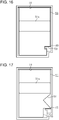
- the shape of the notch 59 may be modified as a first modification example illustrated in Fig. 14 , a second modification example in Fig. 15 , and a third modification example illustrated in Fig. 16 .
- Disposing and the number of the notch 59 can be arbitrarily modified.
- the notch 59 may be provided in plural. In this case, shapes of a plurality of notches 59 may be different from each other.
- the step portion 49 may not be provided on the mounting chamber 18.
- the notch 59 may not need to be opened in a downward direction. According to this, the waste liquid entering into the notch 59 is less likely to hang and drip in the downward direction.
- the notch 59 need not open on an outside surface of a front side of the mounting direction in the accommodating case 51.
- Liquid being ejected by the liquid ejecting head 21 is not limited to ink, and for example, may be liquid of which particles of a functional material are dispersed or mixed in liquid, or the like.
- the apparatus may be configured to perform recording by ejecting liquid of which a material such as an electrode material or a color material (pixel material) used for manufacturing a liquid crystal display, an electroluminescence (EL) display, a surface light-emission display, or the like is dispersed or dissolved.
- the medium S is not limited to paper, but may be plastic film or a thin plate material, or may be a fabric used for a textile printing apparatus, or the like.
Landscapes
- Ink Jet (AREA)
- Coupling Device And Connection With Printed Circuit (AREA)
Abstract
Description
- The present invention relates to a waste liquid container for containing waste liquid such as waste ink and to an attachment used for recovering the waste liquid.
- An ink jet type printer, which is an example of a liquid ejecting apparatus, discharges ink as waste liquid from a liquid ejecting head in order to resolve clogging of the liquid ejecting head, or the like, and in such a printer, a waste liquid container (waste liquid recovery member) for containing the discharged waste liquid is mounted. Also, in the waste liquid container, a circuit board which stores information relating to the amount of liquid contained, or the like, is mounted, and transmitting and receiving of the stored information to and from the printer at the time of being mounted are performed (for example,
JP-A-2009-269209 - In such a waste liquid container, in a case in which the waste liquid leaks from a part connected to the printer, the waste liquid may adhere to a connecting terminal of the circuit board such that a contact failure occurs, and there may thus be a problem that transmitting and receiving of the information are less likely to be performed.
- Also, such a problem is not limited to a waste liquid container mounted in an ink jet type printer which ejects ink and is generally common to a waste liquid container and an attachment which are mounted on a mounting portion including a circuit board.
- An advantage of some aspects of the invention is to provide a waste liquid container and an attachment which are capable of suppressing waste liquid from adhering to a connecting terminal of a circuit board.
- Hereinafter, means of the invention and operation effects thereof will be described.
- According to an aspect of the invention, there is provided a waste liquid container which is detachably mounted by moving in a mounting direction intersecting a gravity direction, with respect to a mounting portion including a projecting portion, in which a substrate connecting portion is mounted, and a discharging portion, which discharges waste liquid, the waste liquid container including an accommodating case that includes a mounting surface which is an external surface that faces internally in the mounting direction and a first side surface and a second side surface which are outside surfaces extending in a direction intersecting a width direction, when a direction intersecting both the gravity direction and the mounting direction is set to the width direction, a waste liquid introducing portion that is connected to the discharging portion at the time of being mounted on the mounting portion, and a circuit board that includes a connecting terminal which is electrically connected to the substrate connecting portion at the time of being mounted on the mounting portion, in which the accommodating case includes a recessed portion which opens on the mounting surface and the first side surface and allows the projecting portion to be inserted therein, when being mounted on the mounting portion, and a notch which opens on the mounting surface and the second side surface vertically below the waste liquid introducing portion, and the connecting terminal is disposed inside the recessed portion.
- According to this configuration, since the connecting terminal of the waste liquid container is disposed inside the recessed portion which opens in a direction intersecting the gravity direction, it is difficult for waste liquid, which adheres and drips further than the connecting terminal disposed at a position where an upper side opens, to adhere to the connecting terminal and for waste liquid, which drips lower than the connecting terminal disposed at a position where a lower side opens, to adhere to the connecting terminal. Further, in the accommodating case, since the notch which opens on the mounting surface and the second side surface is provided vertically below the waste liquid introducing portion, the waste liquid, which leaks from the waste liquid introducing portion and flows and drips on the mounting surface, flows to the notch side. Also, the recessed portion and the notch open on an outside surface of an opposite side in the width direction, and the waste liquid flowing to the notch is less likely to flow into the recessed portion. Therefore, when the notch is disposed lower than the waste liquid introducing portion and the leaked waste liquid is guided to the notch side, the waste liquid can be suppressed from adhering to the connecting terminal of the circuit board inside the recessed portion.
- In the waste liquid container, the circuit board may be mounted in the accommodating case so that the connecting terminal is disposed toward the outside in the width direction in the recessed portion.
- According to this configuration, since the circuit board is mounted in the accommodating case so that the connecting terminal is disposed toward the outside in the width direction inside the recessed portion, the dripping waste liquid can be better suppressed from adhering to the connecting terminal than in a case in which the circuit board is disposed so that the connecting terminal faces upward. In addition, the dripping waste liquid can be better suppressed from adhering to the connecting terminal than in a case in which the circuit board is disposed so that the connecting terminal is face downward.
- In the waste liquid container, the waste liquid container may be removed from the mounting portion by moving the waste liquid container in an unmounting direction which is a direction opposite to the mounting direction, and the notch may extend from the mounting surface in the unmounting direction.
- According to this configuration, the notch extends in the unmounting direction from the mounting surface, and the waste liquid dripping from the mounting surface is guided so as to flow along the notch in the unmounting direction. Accordingly, the waste liquid flows out from the notch in a downward direction and the waste liquid can be suppressed from flowing into the recessed portion by flowing along a bottom portion of the accommodating case.
- In the waste liquid container, the recessed portion may be provided between a reference position and the first side surface in the width direction, and the notch may be provided between the reference position and the second side surface in the accommodating case.
- According to this configuration, in the accommodating case, since the recessed portion is provided on one side in the width direction and the notch is provided on the other side, which is on an opposite side thereto, the waste liquid flowing out from the notch is less likely to flow into the recessed portion compared with a case in which the recessed portion is disposed below the notch. Therefore, the waste liquid can be suppressed from adhering to the connecting terminal of the circuit board inside the recessed portion.
- In the waste liquid container, the notch may be provided right below the waste liquid introducing portion in the accommodating case.
- According to this configuration, in the accommodating case, since the notch is provided right below the waste liquid introducing portion, the waste liquid adhering and dripping from the waste liquid introducing portion can be naturally guided to the notch side.
- According to another aspect of the invention, there is provided an attachment which is mounted by moving in a mounting direction intersecting a gravity direction, with respect to a mounting portion including a projecting portion, in which a substrate connecting portion is mounted, and a discharging portion, which discharges waste liquid, the attachment including an accommodating case that includes a mounting surface which is an external surface that faces internally in the mounting direction and a first side surface and a second side surface which are outside surfaces extending in a direction intersecting a width direction, when a direction intersecting both the gravity direction and the mounting direction is set to the width direction, a waste liquid introducing portion that is connected to the discharging portion at the time of being mounted on the mounting portion, and a circuit board that includes a connecting terminal which is electrically connected to the substrate connecting portion at the time of being mounted on the mounting portion, in which the accommodating case includes a recessed portion which opens on the mounting surface and the first side surface and allows the projecting portion to be inserted therein, when being mounted on the mounting portion, and a notch which opens on the mounting surface and the second side surface vertically below the waste liquid introducing portion, and the connecting terminal is disposed inside the recessed portion.
- According to this configuration, operational effects the same as those in the waste liquid container can be obtained.
- Embodiments of the invention will now be described by way of example only with reference to the accompanying drawings, wherein like numbers reference like elements.
-
Fig. 1 is a perspective view of a liquid ejecting apparatus in which a waste liquid container of an embodiment is to be mounted. -
Fig. 2 is a sectional view of the liquid ejecting apparatus inFig. 1 with the waste liquid container mounted. -
Fig. 3 is a front view illustrating a configuration of a mounting portion included in the liquid ejecting apparatus inFig. 1 . -
Fig. 4 is a perspective view of the mounting portion inFig. 3 . -
Fig. 5 is a top view of the waste liquid container of the embodiment. -
Fig. 6 is a bottom view of the waste liquid container inFig. 5 . -
Fig. 7 is a perspective view of the waste liquid container ofFig. 5 . -
Fig. 8 is a perspective view of the waste liquid container inFig. 5 . -
Fig. 9 is a side view of one side of the waste liquid container inFig. 5 . -
Fig. 10 is a side view of the other side of the waste liquid container inFig. 5 . -
Fig. 11 is a rear view of the waste liquid container inFig. 5 . -
Fig. 12 is a front view of the waste liquid container inFig. 5 . -
Fig. 13 is a sectional view illustrating a mounted state of an attachment of the embodiment. -
Fig. 14 is a front view illustrating a mounted state of a waste liquid container of a first modification example. -
Fig. 15 is a front view illustrating a mounted state of a waste liquid container of a second modification example. -
Fig. 16 is a front view illustrating a mounted state of a waste liquid container of a third modification example. -
Fig. 17 is a front view illustrating a mounted state of a waste liquid container of a fourth modification example. -
Fig. 18 is a front view illustrating a mounted state of a waste liquid container of a fifth modification example. -
Fig. 19 is a front view illustrating a mounted state of a waste liquid container of a sixth modification example. - Hereinafter, embodiments of a liquid ejecting apparatus will be described with respect to the drawings. The liquid ejecting apparatus is, for example, an ink jet type printer which performs recording (printing) by ejecting ink, which is an example of a liquid, onto a medium such as paper.
- As illustrated in
Fig. 1 andFig. 2 , the liquid ejectingapparatus 11 is provided with arectangular case 12, an opening and closinglid 13 which is mounted to be rotatable with respect to thecase 12, an opening andclosing panel 14, and an opening andclosing cover 15. When a side in which the opening and closinglid 13 is mounted is set to a top side of thecase 12 and a side in which a rotation shaft of the opening and closinglid 13 is disposed is set to a rear side of thecase 12, the opening and closinglid 13 is disposed in a position like the opening position illustrated inFig. 1 and the closed position illustrated inFig. 2 by being rotated by a predetermined angle around a rear end of theclosing lid 13. - Inside the
case 12, a liquid ejectinghead 21 including a plurality ofnozzles 20 which are capable of ejecting liquid, acarriage 22 which reciprocates while holding the liquid ejectinghead 21, a transportingroller 23 which transports a medium S, a medium supportingportion 24 which is disposed on a transporting path of the medium S, aguide shaft 25, and amaintenance mechanism 30 which performs maintenance of the liquid ejectinghead 21 are accommodated. In addition, theliquid ejecting apparatus 11 is provided with acontroller 100, which controls an operation of a configuration component including the liquid ejectinghead 21 and themaintenance mechanism 30, at a predetermined position inside thecase 12. - The
guide shaft 25 extends in a moving direction X intersecting ("orthogonal to" in the embodiment) the gravity direction Z. In addition, in thecarriage 22, aliquid container 26 which contains liquid ejected by the liquid ejectinghead 21 is detachably mounted. - The liquid ejecting
head 21 reciprocates in the moving direction X under control of thecontroller 100 while held by thecarriage 22. In addition, the transportingroller 23 transports the medium S onto themedium supporting portion 24 in a transporting direction Y intersecting ("orthogonal to" in the embodiment) both the gravity direction Z and the moving direction X under control of thecontroller 100. The liquid ejectinghead 21 performs printing (recording) by ejecting liquid supplied from theliquid container 26 onto the medium S supported by themedium supporting portion 24, while reciprocating in the moving direction X, under control of thecontroller 100. - The
medium supporting portion 24 and themaintenance mechanism 30 are disposed parallel to each other in the moving direction X of the liquid ejectinghead 21. In addition, themaintenance mechanism 30 includes acap 31 disposed on one end side of the moving direction X, awiper 32 for sweeping the liquid ejectinghead 21, and asuction pump 34 connected via thecap 31 and asuction tube 33. - In the embodiment, a position where the
cap 31 is placed in a moving region of theliquid ejecting head 21 in the moving direction X is referred to as a home position of theliquid ejecting head 21. In addition, a side where thecap 31 is placed in the moving direction X is referred to as a home side, and a side opposite to the home side is referred to as an opposite home side. - The opening and closing
panel 14 mounted on a front side of thecase 12 is disposed at a closed position illustrated inFig. 1 and at an opening position illustrated inFig. 2 by being rotated by approximately 90 degrees with respect to an upper end side. In the opening and closingpanel 14, apanel 16, which performs an operation of theliquid ejecting apparatus 11 or displays an operation state, or the like of theliquid ejecting apparatus 11, is disposed. - The opening and closing
cover 15, which is mounted on a lower side of the opening and closingpanel 14 of a front side of thecase 12, is disposed at a closing position illustrated inFig. 1 and at an opening position illustrated inFig. 2 by being rotated by approximately 90 degrees with respect to a lower end side. - When the opening and closing
panel 14 and the opening and closingcover 15 are disposed at the opening position as illustrated inFig. 2 , acontainer cover 17, which is mounted to be detachable with respect to thecase 12, is exposed. Thecontainer cover 17 covers an opening of a mountingchamber 18 in which thewaste liquid container 50 is detachably mounted, and thecontainer cover 17 covering the opening has a function of applying a force to thewaste liquid container 50 such that thewaste liquid container 50 is not detached from the mountingchamber 18. In addition, inside the mountingchamber 18, the mountingportion 40, which is connected to thewaste liquid container 50 inserted into the mountingchamber 18, is provided. Also, thecontainer cover 17 may be attached to thecase 12 by using a screw, or the like. - The
waste liquid container 50 contains liquid which is discharged as waste liquid from theliquid ejecting head 21, and thewaste liquid container 50 may accommodate anabsorber 50a which is capable of absorbing the waste liquid therein. Also, in a case in which the container is filled with the waste liquid, and the like, thewaste liquid container 50 may be exchanged for a new waste liquid container by removing thewaste liquid container 50 from the mountingchamber 18. - In the embodiment, since the mounting
portion 40 is positioned inside the mountingchamber 18 which has an opening facing forward (downstream of transporting direction Y), a direction toward an upstream side of the transporting direction Y is specified as a mounting direction with respect to the mountingportion 40 of thewaste liquid container 50, and a direction toward a downstream side of the transporting direction Y is specified as the unmounting direction of the mountingportion 40. That is, thewaste liquid container 50 is mounted on the mountingportion 40 by being moved in the mounting direction intersecting the gravity direction Z and is detached from the mountingportion 40 by being moved in the unmounting direction, which is a direction opposite to the mounting direction. - The
suction pump 34 constituting themaintenance mechanism 30 is connected to thewaste liquid container 50 mounted on the mountingchamber 18 through the dischargingtube 35. In addition, thecap 31 is supported by a supportingframe 37 inside thecase 12 through an energizingmember 36. Thecap 31 is configured to be movable to an opening position distant from theliquid ejecting head 21 and to a capping position (position illustrated inFig. 2 ) in contact with theliquid ejecting head 21 so as to surround thenozzles 20 in response to an energizing force of the energizingmember 36 by a moving mechanism, which is not illustrated. - The
maintenance mechanism 30 performs a maintenance operation of theliquid ejecting head 21 in response to control of thecontroller 100 so that theliquid ejecting head 21 has favorable ejecting characteristics. For example, at the time of power-off when theliquid ejecting head 21 is not ejecting liquid, theliquid ejecting head 21 is disposed at the home position. - The
cap 31 is moved to a capping position, and capping for forming a closing space where thenozzles 20 open is performed. Because of the capping, clogging of thenozzles 20 due to drying out is less likely to occur. - The
maintenance mechanism 30 may also drive thesuction pump 34 while capping is performed, and suction cleaning for forcedly causing the liquid inside theliquid ejecting head 21 to flow from thenozzles 20 is performed. Also, pressurization cleaning for causing the liquid to flow from thenozzle 20 can be performed by pressurizing the liquid of theliquid ejecting head 21. - In a case in which an ejection failure of the liquid due to clogging of the
nozzles 20, or the like occurs, cleaning including suction cleaning and pressurization cleaning may be performed at the time of initial charging when a flow path to thenozzle 20 is filled with liquid, and may be performed, in response to a user operation, as a maintenance operation to address an ejection failure. In addition, cleaning can be periodically performed after a predetermined time has elapsed. - After the cleaning, in a state in which an inside of the
cap 31 opens to the atmosphere when thecap 31 is opened to the opening position, or the like, an idling suction for driving thesuction pump 34 is performed again, and the waste liquid remaining inside thecap 31 is sucked out. The liquid flowing from theliquid ejecting head 21 as a result of the cleaning and the idling suction is stored in thewaste liquid container 50 through the dischargingtube 35 and the mountingportion 40 as waste liquid that includes air bubbles, a solute component of thickened liquid, or the like. - Next, a configuration of the mounting
portion 40 will be described in detail. - As illustrated in
Fig. 3 andFig. 4 , the mountingportion 40 includes a discharging portion 41 (refer toFig. 3 ) that discharges the waste liquid by passing through the discharging tube 35 (refer toFig. 2 ), a lockingportion 42, and a projectingportion 44 in which asubstrate connecting portion 43 is mounted. - The locking
portion 42 is constituted by, for example, a plate spring locking thewaste liquid container 50 inserted into the mountingchamber 18. Thesubstrate connecting portion 43 is electrically connected to the controller 100 (refer toFig. 2 ). In addition, the projectingportion 44 includes a pair ofguide projection portions 44a projecting upward and downward. - As illustrated in
Fig. 3 , in the mountingportion 40, the dischargingportion 41 is disposed further upward than thesubstrate connecting portion 43. Inside the mountingchamber 18, in a side lower than the dischargingportion 41, astep portion 49 extending in the mounting direction toward the inside from the vicinity of an opening of the mountingchamber 18 may be provided. In addition, in the mountingchamber 18, it is preferable that, in the width direction in a case in which a direction in the moving direction X is set to a width direction, the dischargingportion 41 and thestep portion 49 be disposed on the home side (right side inFig. 3 ), further than a predetermined reference position (for example, center of the mounting portion 40), and the lockingportion 42 and the projectingportion 44 be disposed on the opposite home side (left side inFig. 3 ), further than the reference position in the width direction. - Next, embodiments of the
waste liquid container 50 will be described with reference to the drawings. - As illustrated in
Fig. 4 , thewaste liquid container 50 includes anaccommodating case 51, which has a box-shaped bottom, in which a side, which becomes an upper portion when mounted to the mountingportion 40, opens, and alid member 52 covering an opening of theaccommodating case 51. - As illustrated in
Fig. 5 to Fig. 8 , thewaste liquid container 50 has a substantially rectangular shape where the mounting direction (transporting direction Y) becomes the longitudinal direction. Theaccommodating case 51 includes ahandle portion 51a on an end portion of a front side in the mounting direction. At the time of attaching and detaching thewaste liquid container 50 to and from the mounting portion 40 (refer toFig. 4 ), a user places their hand on thehandle portion 51a, thewaste liquid container 50 can be inserted into the mounting chamber 18 (refer toFig. 4 ) or taken out from the mountingchamber 18. - As illustrated in
Fig. 9 to Fig. 11 , when a direction intersecting both of the gravity direction Z and the mounting direction is set to a width direction (direction along moving direction X), theaccommodating case 51 includes a mountingsurface 53 which is an outside surface present inside in the mounting direction, abottom surface 54 which becomes a lower surface at the time of mounting, and a pair of side surfaces 55 (first side surface 55F and second side surface 55S) which is an outside surface extending in a direction intersecting the width direction. - As illustrated in
Fig. 9 , thewaste liquid container 50 is provided with acircuit board 56 including a connecting terminal 56a electrically connected to the substrate connecting portion 43 (refer toFig. 4 ), at the time of being mounted on the mounting portion 40 (refer toFig. 4 ).
In thecircuit board 56, information of an amount of containing of thewaste liquid container 50, and the like is stored. In addition, in the first side surface 55F of theaccommodating case 51, an engagingprojection portion 57 which is engaged to the locking portion 42 (refer toFig. 4 ) in a case of being inserted to the mounting chamber 18 (refer toFig. 4 ) is projected. - As illustrated in
Fig. 12 , thewaste liquid container 50 is provided with a wasteliquid introducing portion 61 connected to the dischargingportion 41 at the time of being mounted on the mountingportion 40. Theaccommodating case 51 includes a recessedportion 58 which allows the projectingportion 44 to be inserted, which opens on the mountingsurface 53 and the first side surface 55F, at the time of being mounted on the mountingportion 40, and anotch 59 which opens on at least the mountingsurface 53 and the second side surface 55S vertically below the wasteliquid introducing portion 61. - In the
accommodating case 51, it is preferable that thenotch 59 be provided right below the wasteliquid introducing portion 61. In addition, in theaccommodating case 51, it is preferable that the recessedportion 58 be provided between a predetermined reference position (for example, center) and the first side surface 55F in the width direction, and the wasteliquid introducing portion 61 and thenotch 59 are provided between the reference position described above and the second side surface 55S in the width direction. Also, the reference position of this case may be corresponded to a reference position when the dischargingportion 41 and the projectingportion 44 are disposed in the mountingchamber 18. - The
circuit board 56 is disposed inside the recessedportion 58 with the connecting terminal 56a. In addition, in the recessedportion 58, a guidinggroove 58a which can be engaged with theguide projection portion 44a of the projectingportion 44 is recessed and provided on an upper side and a lower side of thecircuit board 56. - It is preferable that the
circuit board 56 be mounted in theaccommodating case 51 so that the connecting terminal 56a is disposed toward the outside in the width direction inside the recessedportion 58. In addition, it is preferable that thenotch 59 be formed to extend from the mountingsurface 53 in the unmounting direction. - Next, attaching and detaching operation with respect to the mounting
portion 40 of thewaste liquid container 50 and action of thewaste liquid container 50 will be described. - When the
waste liquid container 50 is moved in the mounting direction with respect to the mountingportion 40, the lockingportion 42 is engaged with the engagingprojection portion 57, and movement in the unmounting direction of thewaste liquid container 50 is suppressed. In addition, the dischargingportion 41 is connected to the wasteliquid introducing portion 61 of thewaste liquid container 50 by movement in the mounting direction of thewaste liquid container 50, the connecting terminal 56a of thecircuit board 56 comes into contact with thesubstrate connecting portion 43, and thecircuit board 56 and the controller 100 (refer toFig. 2 ) are electrically connected to each other. At this time, when theguide projection portion 44a of the projectingportion 44 is engaged with the guidinggroove 58a of thewaste liquid container 50, the connecting terminal 56a of thecircuit board 56 is accurately positioned with respect to thesubstrate connecting portion 43. - The
controller 100 detects that thewaste liquid container 50 is mounted, by being electrically connected to thecircuit board 56, and reads information stored in thecircuit board 56. Also, in a case in which a vacancy is present in the amount of containing of the waste liquid container 50 (in other words, the read information indicates thewaste liquid container 50 is empty or at least not full), introducing the waste liquid to thewaste liquid container 50 is allowed. - Accordingly, when a maintenance operation such as cleaning in the
liquid ejecting apparatus 11 is performed, the waste liquid discharged from theliquid ejecting head 21 is introduced to thewaste liquid container 50 through the dischargingportion 41 and the wasteliquid introducing portion 61. Thecontroller 100 subtracts an amount of the discharged waste liquid from the amount of containing of (that is, the amount of free space in) the storedwaste liquid container 50, if an amount of discharging of the waste liquid is close to the amount of containing, the controller informs a command that thewaste liquid container 50 needs to be exchanged through apanel 16, and the like. - However, although an amount of absorbing of the
absorber 50a contained in thewaste liquid container 50 remains, for example, in a case in which the waste liquid is solidified near the wasteliquid introducing portion 61 inside thewaste liquid container 50, or the like, the waste liquid discharged from the dischargingportion 41 over-flows from thewaste liquid container 50. When the leaked waste liquid as described above is attached to the connecting terminal 56a or thesubstrate connecting portion 43, electrical connection of both is inhibited, and there is a concern that information cannot be accepted. - In this point, since the
waste liquid container 50 of the embodiment includes thenotch 59 which opens on the mountingsurface 53 vertically below the wasteliquid introducing portion 61, when the waste liquid leaked from a vicinity of the wasteliquid introducing portion 61 opening on the mountingsurface 53 hangs and drips along the mountingsurface 53 in a downward direction, the waste liquid enters into thenotch 59 and flows along thenotch 59 intersecting the mountingsurface 53 in the unmounting direction. Since thenotch 59 opens on the second side surface 55S and thebottom surface 54, when the waste liquid flows from thenotch 59, it flows to a side of the home side of thewaste liquid container 50 or a bottom portion of thewaste liquid container 50. - With respect to that, since the
circuit board 56 including the connecting terminal 56a is accommodated in the recessedportion 58 opening on the first side surface 55F of the opposite home side of thewaste liquid container 50, even when the waste liquid flows to a side of the home side of thewaste liquid container 50 or a lower side of thewaste liquid container 50, the waste liquid is less likely to enter into the recessedportion 58. Therefore, when thecircuit board 56 is accommodated inside the recessedportion 58, attaching of the leaked waste liquid to the connecting terminal 56a of thecircuit board 56 is suppressed. - According to the embodiment, effects as follows can be obtained.
- (1) Since the connecting terminal 56a of the
waste liquid container 50 is disposed inside the recessedportion 58 opening in a direction intersecting the gravity direction Z, the waste liquid hanging and dripping further than the connecting terminal 56a disposed on a position in which an upper side opens is less likely to be attached, and also, the waste liquid dripping lower than the connecting terminal 56a disposed on a position in which a lower side opens is less likely to be attached. Further, in theaccommodating case 51, since thenotch 59 opening on the mountingsurface 53 and the second side surface 55S is provided vertically below the wasteliquid introducing portion 61, the waste liquid, which is leaked from the wasteliquid introducing portion 61 and dripping from the mountingsurface 53, flows to a side of thenotch 59. Since the recessedportion 58 and thenotch 59 open to an outside surface of an opposite side in the width direction, the waste liquid flowing to thenotch 59 is less likely to be flowing into the recessedportion 58. Therefore, when thenotch 59 is disposed on a lower side than the wasteliquid introducing portion 61, and the leaked waste liquid is guided to a side of thenotch 59, attaching of the waste liquid with respect to the connecting terminal 56a of thecircuit board 56 inside the recessedportion 58 can be suppressed. - (2) Since the
circuit board 56 is mounted on theaccommodating case 51 so that the connecting terminal 56a is disposed toward the outside (the first side 55F) in the width direction in the recessedportion 58, attaching of the waste liquid hanging and dripping to the connecting terminal 56a can be suppressed, better than in a case in which thecircuit board 56 is disposed so that the connecting terminal 56a is disposed upward. In addition, better than in a case in which thecircuit board 56 is disposed so that the connecting terminal 56a is disposed in the downward direction, attaching of the waste liquid dripping down to the connecting terminal 56a can be suppressed. - (3) The
notch 59 extends from the mountingsurface 53 in the unmounting direction, and the waste liquid dripping from the mountingsurface 53 is guided so as to flow along thenotch 59 toward the unmounting direction. Accordingly, the waste liquid flows from thenotch 59 in a downward direction, and the waste liquid can be suppressed from flowing into the recessedportion 58 by flowing along a bottom portion of theaccommodating case 51. - (4) In the
accommodating case 51, since the recessedportion 58 is provided on one side of the width direction, and thenotch 59 is provided on the other side of an opposite side thereof, more than a case in which the recessedportion 58 is disposed on a lower side of thenotch 59, the waste liquid flowing from thenotch 59 is less likely to enter into the recessedportion 58. Therefore, attaching of the waste liquid with respect to the connecting terminal 56a of thecircuit board 56 inside the recessedportion 58 can be suppressed. - (5) In the
accommodating case 51, since thenotch 59 is provided right below the wasteliquid introducing portion 61, the waste liquid hanging and dripping from the wasteliquid introducing portion 61 can be naturally guided to a side of thenotch 59. - Also, the embodiment described above may be modified like a modification example to be illustrated as follows. In addition, the embodiment described above and each modification can be arbitrarily combined.
- As illustrated in
Fig. 13 , theattachment 70 may be mounted on the mountingportion 40. Theattachment 70 is configured same as thewaste liquid container 50, but it is different from thewaste liquid container 50 in that the waste liquid is not contained therein. Theattachment 70 introduces the waste liquid to thewaste liquid tank 71 provided outside thecase 12 through a dischargingflow path 72, when the wasteliquid introducing portion 61 is connected to the dischargingportion 41. After theattachment 70 is mounted on the mountingportion 40, the attachment is fixed by a screw, or the like, andneed not be detached from theliquid ejecting apparatus 11. - A shape of the
notch 59 can be arbitrarily modified. For example, the shape of thenotch 59 may be modified as a first modification example illustrated inFig. 14 , a second modification example inFig. 15 , and a third modification example illustrated inFig. 16 . - Disposing and the number of the
notch 59 can be arbitrarily modified. For example, like a fourth modification example illustrated inFig. 17 , a fifth modification example illustrated inFig. 18 , or a sixth modification example illustrated inFig. 19 , thenotch 59 may be provided in plural. In this case, shapes of a plurality ofnotches 59 may be different from each other. - As illustrated in
Fig. 18 and Fig. 19 , thestep portion 49 may not be provided on the mountingchamber 18. In this case, thenotch 59 may not need to be opened in a downward direction. According to this, the waste liquid entering into thenotch 59 is less likely to hang and drip in the downward direction. - The
notch 59 need not open on an outside surface of a front side of the mounting direction in theaccommodating case 51. - Liquid being ejected by the
liquid ejecting head 21 is not limited to ink, and for example, may be liquid of which particles of a functional material are dispersed or mixed in liquid, or the like. For example, the apparatus may be configured to perform recording by ejecting liquid of which a material such as an electrode material or a color material (pixel material) used for manufacturing a liquid crystal display, an electroluminescence (EL) display, a surface light-emission display, or the like is dispersed or dissolved. - The medium S is not limited to paper, but may be plastic film or a thin plate material, or may be a fabric used for a textile printing apparatus, or the like.
- The entire disclosure of
Japanese Patent Application No. 2016-005017, filed January 14, 2016 - The foregoing description has been given by way of example only and it will be appreciated by a person skilled in the art that modifications can be made without departing from the scope of the present invention as defined by the claims.
Claims (6)
- A waste liquid container (50) which is detachably mounted in accordance with moving in a mounting direction (Y) intersecting a gravity direction (Z), with respect to a mounting portion (40) including a projecting portion (44), to which a substrate connecting portion (43) is mounted, and a discharging portion (41), which discharges waste liquid, the waste liquid container comprising:an accommodating case (51) that includes a mounting surface (53) which is an external surface that faces internally in the mounting direction and a first side surface (55F) and a second side surface (55S) which are outside surfaces extending in a direction intersecting a width direction, when a direction intersecting both the gravity direction and the mounting direction is set to the width direction (X);a waste liquid introducing portion (61) that is connected to the discharging portion at the time of being mounted on the mounting portion; anda circuit board (56) that includes a connecting terminal (56a) which is electrically connected to the substrate connecting portion at the time of being mounted on the mounting portion,wherein the accommodating case includes a recessed portion (58) which opens on the mounting surface and the first side surface and allows the projecting portion to be inserted therein, when being mounted on the mounting portion, and a notch (59) which opens on the mounting surface and the second side surface vertically below the waste liquid introducing portion, andwherein the connecting terminal (56a) is disposed inside the recessed portion (58).
- The waste liquid container according to Claim 1,
wherein the circuit board (56) is mounted in the accommodating case (51) so that the connecting terminal (56a) is disposed toward the outside in the width direction in the recessed portion. - The waste liquid container according to Claim 1 or Claim 2,
wherein the waste liquid container is removed from the mounting portion in accordance with moving in an unmounting direction, which is a direction opposite to the mounting direction, and
wherein the notch (59) extends from the mounting surface (53) in the unmounting direction. - The waste liquid container according to any one of the preceding claims,
wherein, in the accommodating case, the recessed portion (58) is provided between a reference position and the first side surface (55F) in the width direction, and the notch (59) is provided between the reference position and the second side surface (55S). - The waste liquid container according to any one of the preceding claims,
wherein, in the accommodating case, the notch (59) is provided right below the waste liquid introducing portion (61). - An attachment (70) which is mounted by moving in a mounting direction (Y) intersecting a gravity direction (Z) with respect to a mounting portion (40) including a projecting portion (43), in which a substrate connecting portion (43a) is mounted, and a discharging portion (41), which discharges waste liquid, the attachment comprising:an accommodating case that includes a mounting surface which is an external surface that faces internally in the mounting direction and a first side surface and a second side surface which are outside surfaces extending in a direction intersecting a width direction, when a direction intersecting both the gravity direction and the mounting direction is set to the width direction;a waste liquid introducing portion (61) that is connected to the discharging portion at the time of being mounted on the mounting portion; anda circuit board that includes a connecting terminal which is electrically connected to the substrate connecting portion at the time of being mounted on the mounting portion,wherein the accommodating case includes a recessed portion which opens on the mounting surface and the first side surface and allows the projecting portion to be inserted therein, when being mounted on the mounting portion, and a notch which opens on the mounting surface and the second side surface vertically below the waste liquid introducing portion, andwherein the connecting terminal is disposed inside the recessed portion.
Applications Claiming Priority (1)
| Application Number | Priority Date | Filing Date | Title |
|---|---|---|---|
| JP2016005017A JP6714820B2 (en) | 2016-01-14 | 2016-01-14 | Waste liquid container and attachment |
Publications (3)
| Publication Number | Publication Date |
|---|---|
| EP3192658A2 true EP3192658A2 (en) | 2017-07-19 |
| EP3192658A3 EP3192658A3 (en) | 2017-11-01 |
| EP3192658B1 EP3192658B1 (en) | 2019-07-31 |
Family
ID=57796242
Family Applications (1)
| Application Number | Title | Priority Date | Filing Date |
|---|---|---|---|
| EP17151381.5A Active EP3192658B1 (en) | 2016-01-14 | 2017-01-13 | Waste liquid container and attachment |
Country Status (4)
| Country | Link |
|---|---|
| US (1) | US10022972B2 (en) |
| EP (1) | EP3192658B1 (en) |
| JP (1) | JP6714820B2 (en) |
| CN (1) | CN106965561B (en) |
Families Citing this family (8)
| Publication number | Priority date | Publication date | Assignee | Title |
|---|---|---|---|---|
| JP6972559B2 (en) | 2017-01-13 | 2021-11-24 | セイコーエプソン株式会社 | Waste liquid container and attachment of waste liquid container |
| JP6969162B2 (en) | 2017-05-31 | 2021-11-24 | セイコーエプソン株式会社 | Waste liquid container and liquid injection device |
| JP7091689B2 (en) | 2018-02-13 | 2022-06-28 | セイコーエプソン株式会社 | Liquid sprayer |
| JP7119815B2 (en) * | 2018-09-18 | 2022-08-17 | セイコーエプソン株式会社 | Waste liquid container and attachment |
| JP7125007B2 (en) | 2018-09-19 | 2022-08-24 | セイコーエプソン株式会社 | recording device |
| US10841443B2 (en) | 2018-09-20 | 2020-11-17 | Seiko Epson Corporation | Recording apparatus |
| JP7463112B2 (en) | 2020-01-15 | 2024-04-08 | キヤノン株式会社 | Liquid ejection device |
| JP2023180549A (en) * | 2022-06-09 | 2023-12-21 | ブラザー工業株式会社 | Waste liquid storage container and liquid discharge device |
Citations (1)
| Publication number | Priority date | Publication date | Assignee | Title |
|---|---|---|---|---|
| JP2009269209A (en) | 2008-04-30 | 2009-11-19 | Seiko Epson Corp | Waste liquid collector |
Family Cites Families (12)
| Publication number | Priority date | Publication date | Assignee | Title |
|---|---|---|---|---|
| JP2003266747A (en) * | 2002-03-20 | 2003-09-24 | Seiko Epson Corp | Recording device |
| JP4561395B2 (en) * | 2005-02-18 | 2010-10-13 | セイコーエプソン株式会社 | Attachment and liquid supply device |
| KR101200413B1 (en) * | 2007-06-21 | 2012-11-13 | 삼성전자주식회사 | Waste ink container, waste ink storing apparatus and ink jet printer including the same |
| JP2009202522A (en) * | 2008-02-29 | 2009-09-10 | Seiko Epson Corp | Waste liquid collector and liquid jetting apparatus |
| JP2010260261A (en) | 2009-05-07 | 2010-11-18 | Ricoh Co Ltd | Image forming apparatus |
| JP5831678B2 (en) | 2011-02-28 | 2015-12-09 | セイコーエプソン株式会社 | Liquid ejector |
| CN102673166B (en) * | 2011-03-08 | 2015-09-09 | 精工爱普生株式会社 | Waste liquid packaging container and liquid consuming device |
| JP6007555B2 (en) * | 2012-04-10 | 2016-10-12 | セイコーエプソン株式会社 | Waste liquid collector |
| JP5803975B2 (en) * | 2013-05-09 | 2015-11-04 | セイコーエプソン株式会社 | Liquid ejector |
| EP2939837B1 (en) | 2014-04-30 | 2018-06-06 | Seiko Epson Corporation | Waste liquid container, attachment, waste liquid collection unit, and liquid ejecting apparatus |
| JP6349929B2 (en) * | 2014-04-30 | 2018-07-04 | セイコーエプソン株式会社 | Waste liquid container and liquid ejecting apparatus |
| JP2016010900A (en) | 2014-06-27 | 2016-01-21 | セイコーエプソン株式会社 | Waste liquid container and liquid ejecting apparatus |
-
2016
- 2016-01-14 JP JP2016005017A patent/JP6714820B2/en active Active
- 2016-12-23 CN CN201611205727.9A patent/CN106965561B/en active Active
-
2017
- 2017-01-05 US US15/399,126 patent/US10022972B2/en active Active
- 2017-01-13 EP EP17151381.5A patent/EP3192658B1/en active Active
Patent Citations (1)
| Publication number | Priority date | Publication date | Assignee | Title |
|---|---|---|---|---|
| JP2009269209A (en) | 2008-04-30 | 2009-11-19 | Seiko Epson Corp | Waste liquid collector |
Also Published As
| Publication number | Publication date |
|---|---|
| JP2017124541A (en) | 2017-07-20 |
| CN106965561A (en) | 2017-07-21 |
| EP3192658A3 (en) | 2017-11-01 |
| EP3192658B1 (en) | 2019-07-31 |
| JP6714820B2 (en) | 2020-07-01 |
| CN106965561B (en) | 2020-09-22 |
| US20170203575A1 (en) | 2017-07-20 |
| US10022972B2 (en) | 2018-07-17 |
Similar Documents
| Publication | Publication Date | Title |
|---|---|---|
| EP3192658B1 (en) | Waste liquid container and attachment | |
| US9840078B2 (en) | Waste liquid reservoir and liquid ejecting apparatus | |
| EP2703167A2 (en) | Storage unit holding member and holding member | |
| CN112238680B (en) | Liquid ejecting apparatus | |
| US10245838B2 (en) | Liquid ejecting apparatus | |
| JP7139885B2 (en) | LIQUID EJECTING DEVICE, MAINTENANCE METHOD OF LIQUID EJECTING DEVICE | |
| JP2018111279A (en) | Waste liquid container and attachment | |
| JP2016030382A (en) | Printing device | |
| CN104228348B (en) | Maintenance unit and liquid injection apparatus | |
| US10569539B2 (en) | Liquid ejection apparatus | |
| US20140035996A1 (en) | Print head servicing units and methods | |
| JP2019104124A (en) | Liquid discharge device | |
| JP2021011058A (en) | Liquid injection device, maintenance method of liquid injection device | |
| US9254670B2 (en) | Liquid ejecting apparatus, adapter, and liquid supply system | |
| US10059109B2 (en) | Liquid ejecting apparatus | |
| JP2019069587A (en) | Liquid jetting device | |
| JP6464793B2 (en) | Moisturizing apparatus and inkjet recording apparatus | |
| US10556434B2 (en) | Inkjet recording apparatus | |
| JP7632017B2 (en) | Recording device | |
| JP7502958B2 (en) | Liquid ejection device and waste liquid tank | |
| JP2020011434A (en) | Liquid ejection device | |
| US10981378B2 (en) | Image-forming apparatus, non-transitory computer-readable medium storing computer-readable instructions, and method for discharging deposits on a filter of an image-forming apparatus | |
| JP7323029B2 (en) | LIQUID EJECTING DEVICE, MAINTENANCE METHOD OF LIQUID EJECTING DEVICE | |
| JP2019069540A (en) | Inkjet recording device | |
| JP2014104708A (en) | Liquid jetting device, liquid jetting method |
Legal Events
| Date | Code | Title | Description |
|---|---|---|---|
| PUAI | Public reference made under article 153(3) epc to a published international application that has entered the european phase |
Free format text: ORIGINAL CODE: 0009012 |
|
| STAA | Information on the status of an ep patent application or granted ep patent |
Free format text: STATUS: THE APPLICATION HAS BEEN PUBLISHED |
|
| AK | Designated contracting states |
Kind code of ref document: A2 Designated state(s): AL AT BE BG CH CY CZ DE DK EE ES FI FR GB GR HR HU IE IS IT LI LT LU LV MC MK MT NL NO PL PT RO RS SE SI SK SM TR |
|
| AX | Request for extension of the european patent |
Extension state: BA ME |
|
| PUAL | Search report despatched |
Free format text: ORIGINAL CODE: 0009013 |
|
| AK | Designated contracting states |
Kind code of ref document: A3 Designated state(s): AL AT BE BG CH CY CZ DE DK EE ES FI FR GB GR HR HU IE IS IT LI LT LU LV MC MK MT NL NO PL PT RO RS SE SI SK SM TR |
|
| AX | Request for extension of the european patent |
Extension state: BA ME |
|
| RIC1 | Information provided on ipc code assigned before grant |
Ipc: B41J 2/17 20060101ALI20170927BHEP Ipc: B41J 2/165 20060101AFI20170927BHEP |
|
| STAA | Information on the status of an ep patent application or granted ep patent |
Free format text: STATUS: REQUEST FOR EXAMINATION WAS MADE |
|
| STAA | Information on the status of an ep patent application or granted ep patent |
Free format text: STATUS: EXAMINATION IS IN PROGRESS |
|
| 17P | Request for examination filed |
Effective date: 20180502 |
|
| RBV | Designated contracting states (corrected) |
Designated state(s): AL AT BE BG CH CY CZ DE DK EE ES FI FR GB GR HR HU IE IS IT LI LT LU LV MC MK MT NL NO PL PT RO RS SE SI SK SM TR |
|
| 17Q | First examination report despatched |
Effective date: 20180608 |
|
| GRAP | Despatch of communication of intention to grant a patent |
Free format text: ORIGINAL CODE: EPIDOSNIGR1 |
|
| STAA | Information on the status of an ep patent application or granted ep patent |
Free format text: STATUS: GRANT OF PATENT IS INTENDED |
|
| INTG | Intention to grant announced |
Effective date: 20190107 |
|
| GRAJ | Information related to disapproval of communication of intention to grant by the applicant or resumption of examination proceedings by the epo deleted |
Free format text: ORIGINAL CODE: EPIDOSDIGR1 |
|
| STAA | Information on the status of an ep patent application or granted ep patent |
Free format text: STATUS: EXAMINATION IS IN PROGRESS |
|
| GRAJ | Information related to disapproval of communication of intention to grant by the applicant or resumption of examination proceedings by the epo deleted |
Free format text: ORIGINAL CODE: EPIDOSDIGR1 |
|
| STAA | Information on the status of an ep patent application or granted ep patent |
Free format text: STATUS: GRANT OF PATENT IS INTENDED |
|
| GRAS | Grant fee paid |
Free format text: ORIGINAL CODE: EPIDOSNIGR3 |
|
| GRAP | Despatch of communication of intention to grant a patent |
Free format text: ORIGINAL CODE: EPIDOSNIGR1 |
|
| INTC | Intention to grant announced (deleted) | ||
| INTG | Intention to grant announced |
Effective date: 20190523 |
|
| GRAA | (expected) grant |
Free format text: ORIGINAL CODE: 0009210 |
|
| STAA | Information on the status of an ep patent application or granted ep patent |
Free format text: STATUS: THE PATENT HAS BEEN GRANTED |
|
| AK | Designated contracting states |
Kind code of ref document: B1 Designated state(s): AL AT BE BG CH CY CZ DE DK EE ES FI FR GB GR HR HU IE IS IT LI LT LU LV MC MK MT NL NO PL PT RO RS SE SI SK SM TR |
|
| REG | Reference to a national code |
Ref country code: CH Ref legal event code: EP Ref country code: GB Ref legal event code: FG4D |
|
| REG | Reference to a national code |
Ref country code: AT Ref legal event code: REF Ref document number: 1160489 Country of ref document: AT Kind code of ref document: T Effective date: 20190815 |
|
| REG | Reference to a national code |
Ref country code: IE Ref legal event code: FG4D |
|
| REG | Reference to a national code |
Ref country code: DE Ref legal event code: R096 Ref document number: 602017005587 Country of ref document: DE |
|
| REG | Reference to a national code |
Ref country code: NL Ref legal event code: MP Effective date: 20190731 |
|
| REG | Reference to a national code |
Ref country code: LT Ref legal event code: MG4D |
|
| REG | Reference to a national code |
Ref country code: AT Ref legal event code: MK05 Ref document number: 1160489 Country of ref document: AT Kind code of ref document: T Effective date: 20190731 |
|
| PG25 | Lapsed in a contracting state [announced via postgrant information from national office to epo] |
Ref country code: BG Free format text: LAPSE BECAUSE OF FAILURE TO SUBMIT A TRANSLATION OF THE DESCRIPTION OR TO PAY THE FEE WITHIN THE PRESCRIBED TIME-LIMIT Effective date: 20191031 Ref country code: SE Free format text: LAPSE BECAUSE OF FAILURE TO SUBMIT A TRANSLATION OF THE DESCRIPTION OR TO PAY THE FEE WITHIN THE PRESCRIBED TIME-LIMIT Effective date: 20190731 Ref country code: NL Free format text: LAPSE BECAUSE OF FAILURE TO SUBMIT A TRANSLATION OF THE DESCRIPTION OR TO PAY THE FEE WITHIN THE PRESCRIBED TIME-LIMIT Effective date: 20190731 Ref country code: NO Free format text: LAPSE BECAUSE OF FAILURE TO SUBMIT A TRANSLATION OF THE DESCRIPTION OR TO PAY THE FEE WITHIN THE PRESCRIBED TIME-LIMIT Effective date: 20191031 Ref country code: LT Free format text: LAPSE BECAUSE OF FAILURE TO SUBMIT A TRANSLATION OF THE DESCRIPTION OR TO PAY THE FEE WITHIN THE PRESCRIBED TIME-LIMIT Effective date: 20190731 Ref country code: HR Free format text: LAPSE BECAUSE OF FAILURE TO SUBMIT A TRANSLATION OF THE DESCRIPTION OR TO PAY THE FEE WITHIN THE PRESCRIBED TIME-LIMIT Effective date: 20190731 Ref country code: FI Free format text: LAPSE BECAUSE OF FAILURE TO SUBMIT A TRANSLATION OF THE DESCRIPTION OR TO PAY THE FEE WITHIN THE PRESCRIBED TIME-LIMIT Effective date: 20190731 Ref country code: AT Free format text: LAPSE BECAUSE OF FAILURE TO SUBMIT A TRANSLATION OF THE DESCRIPTION OR TO PAY THE FEE WITHIN THE PRESCRIBED TIME-LIMIT Effective date: 20190731 Ref country code: PT Free format text: LAPSE BECAUSE OF FAILURE TO SUBMIT A TRANSLATION OF THE DESCRIPTION OR TO PAY THE FEE WITHIN THE PRESCRIBED TIME-LIMIT Effective date: 20191202 |
|
| PG25 | Lapsed in a contracting state [announced via postgrant information from national office to epo] |
Ref country code: AL Free format text: LAPSE BECAUSE OF FAILURE TO SUBMIT A TRANSLATION OF THE DESCRIPTION OR TO PAY THE FEE WITHIN THE PRESCRIBED TIME-LIMIT Effective date: 20190731 Ref country code: LV Free format text: LAPSE BECAUSE OF FAILURE TO SUBMIT A TRANSLATION OF THE DESCRIPTION OR TO PAY THE FEE WITHIN THE PRESCRIBED TIME-LIMIT Effective date: 20190731 Ref country code: GR Free format text: LAPSE BECAUSE OF FAILURE TO SUBMIT A TRANSLATION OF THE DESCRIPTION OR TO PAY THE FEE WITHIN THE PRESCRIBED TIME-LIMIT Effective date: 20191101 Ref country code: ES Free format text: LAPSE BECAUSE OF FAILURE TO SUBMIT A TRANSLATION OF THE DESCRIPTION OR TO PAY THE FEE WITHIN THE PRESCRIBED TIME-LIMIT Effective date: 20190731 Ref country code: RS Free format text: LAPSE BECAUSE OF FAILURE TO SUBMIT A TRANSLATION OF THE DESCRIPTION OR TO PAY THE FEE WITHIN THE PRESCRIBED TIME-LIMIT Effective date: 20190731 |
|
| PG25 | Lapsed in a contracting state [announced via postgrant information from national office to epo] |
Ref country code: TR Free format text: LAPSE BECAUSE OF FAILURE TO SUBMIT A TRANSLATION OF THE DESCRIPTION OR TO PAY THE FEE WITHIN THE PRESCRIBED TIME-LIMIT Effective date: 20190731 |
|
| PG25 | Lapsed in a contracting state [announced via postgrant information from national office to epo] |
Ref country code: RO Free format text: LAPSE BECAUSE OF FAILURE TO SUBMIT A TRANSLATION OF THE DESCRIPTION OR TO PAY THE FEE WITHIN THE PRESCRIBED TIME-LIMIT Effective date: 20190731 Ref country code: IT Free format text: LAPSE BECAUSE OF FAILURE TO SUBMIT A TRANSLATION OF THE DESCRIPTION OR TO PAY THE FEE WITHIN THE PRESCRIBED TIME-LIMIT Effective date: 20190731 Ref country code: PL Free format text: LAPSE BECAUSE OF FAILURE TO SUBMIT A TRANSLATION OF THE DESCRIPTION OR TO PAY THE FEE WITHIN THE PRESCRIBED TIME-LIMIT Effective date: 20190731 Ref country code: EE Free format text: LAPSE BECAUSE OF FAILURE TO SUBMIT A TRANSLATION OF THE DESCRIPTION OR TO PAY THE FEE WITHIN THE PRESCRIBED TIME-LIMIT Effective date: 20190731 Ref country code: DK Free format text: LAPSE BECAUSE OF FAILURE TO SUBMIT A TRANSLATION OF THE DESCRIPTION OR TO PAY THE FEE WITHIN THE PRESCRIBED TIME-LIMIT Effective date: 20190731 |
|
| PG25 | Lapsed in a contracting state [announced via postgrant information from national office to epo] |
Ref country code: IS Free format text: LAPSE BECAUSE OF FAILURE TO SUBMIT A TRANSLATION OF THE DESCRIPTION OR TO PAY THE FEE WITHIN THE PRESCRIBED TIME-LIMIT Effective date: 20200224 Ref country code: SM Free format text: LAPSE BECAUSE OF FAILURE TO SUBMIT A TRANSLATION OF THE DESCRIPTION OR TO PAY THE FEE WITHIN THE PRESCRIBED TIME-LIMIT Effective date: 20190731 Ref country code: CZ Free format text: LAPSE BECAUSE OF FAILURE TO SUBMIT A TRANSLATION OF THE DESCRIPTION OR TO PAY THE FEE WITHIN THE PRESCRIBED TIME-LIMIT Effective date: 20190731 Ref country code: SK Free format text: LAPSE BECAUSE OF FAILURE TO SUBMIT A TRANSLATION OF THE DESCRIPTION OR TO PAY THE FEE WITHIN THE PRESCRIBED TIME-LIMIT Effective date: 20190731 |
|
| REG | Reference to a national code |
Ref country code: DE Ref legal event code: R097 Ref document number: 602017005587 Country of ref document: DE |
|
| PLBE | No opposition filed within time limit |
Free format text: ORIGINAL CODE: 0009261 |
|
| STAA | Information on the status of an ep patent application or granted ep patent |
Free format text: STATUS: NO OPPOSITION FILED WITHIN TIME LIMIT |
|
| PG2D | Information on lapse in contracting state deleted |
Ref country code: IS |
|
| PG25 | Lapsed in a contracting state [announced via postgrant information from national office to epo] |
Ref country code: IS Free format text: LAPSE BECAUSE OF FAILURE TO SUBMIT A TRANSLATION OF THE DESCRIPTION OR TO PAY THE FEE WITHIN THE PRESCRIBED TIME-LIMIT Effective date: 20191030 |
|
| 26N | No opposition filed |
Effective date: 20200603 |
|
| PG25 | Lapsed in a contracting state [announced via postgrant information from national office to epo] |
Ref country code: MC Free format text: LAPSE BECAUSE OF FAILURE TO SUBMIT A TRANSLATION OF THE DESCRIPTION OR TO PAY THE FEE WITHIN THE PRESCRIBED TIME-LIMIT Effective date: 20190731 Ref country code: SI Free format text: LAPSE BECAUSE OF FAILURE TO SUBMIT A TRANSLATION OF THE DESCRIPTION OR TO PAY THE FEE WITHIN THE PRESCRIBED TIME-LIMIT Effective date: 20190731 |
|
| REG | Reference to a national code |
Ref country code: CH Ref legal event code: PL |
|
| REG | Reference to a national code |
Ref country code: BE Ref legal event code: MM Effective date: 20200131 |
|
| PG25 | Lapsed in a contracting state [announced via postgrant information from national office to epo] |
Ref country code: LU Free format text: LAPSE BECAUSE OF NON-PAYMENT OF DUE FEES Effective date: 20200113 |
|
| PG25 | Lapsed in a contracting state [announced via postgrant information from national office to epo] |
Ref country code: LI Free format text: LAPSE BECAUSE OF NON-PAYMENT OF DUE FEES Effective date: 20200131 Ref country code: CH Free format text: LAPSE BECAUSE OF NON-PAYMENT OF DUE FEES Effective date: 20200131 Ref country code: BE Free format text: LAPSE BECAUSE OF NON-PAYMENT OF DUE FEES Effective date: 20200131 |
|
| PG25 | Lapsed in a contracting state [announced via postgrant information from national office to epo] |
Ref country code: IE Free format text: LAPSE BECAUSE OF NON-PAYMENT OF DUE FEES Effective date: 20200113 |
|
| PG25 | Lapsed in a contracting state [announced via postgrant information from national office to epo] |
Ref country code: MT Free format text: LAPSE BECAUSE OF FAILURE TO SUBMIT A TRANSLATION OF THE DESCRIPTION OR TO PAY THE FEE WITHIN THE PRESCRIBED TIME-LIMIT Effective date: 20190731 Ref country code: CY Free format text: LAPSE BECAUSE OF FAILURE TO SUBMIT A TRANSLATION OF THE DESCRIPTION OR TO PAY THE FEE WITHIN THE PRESCRIBED TIME-LIMIT Effective date: 20190731 |
|
| PG25 | Lapsed in a contracting state [announced via postgrant information from national office to epo] |
Ref country code: MK Free format text: LAPSE BECAUSE OF FAILURE TO SUBMIT A TRANSLATION OF THE DESCRIPTION OR TO PAY THE FEE WITHIN THE PRESCRIBED TIME-LIMIT Effective date: 20190731 |
|
| PGFP | Annual fee paid to national office [announced via postgrant information from national office to epo] |
Ref country code: GB Payment date: 20251127 Year of fee payment: 10 |
|
| PGFP | Annual fee paid to national office [announced via postgrant information from national office to epo] |
Ref country code: FR Payment date: 20251128 Year of fee payment: 10 |
|
| PGFP | Annual fee paid to national office [announced via postgrant information from national office to epo] |
Ref country code: DE Payment date: 20251203 Year of fee payment: 10 |