EP3192606A1 - Electrical discharge machining apparatus - Google Patents
Electrical discharge machining apparatus Download PDFInfo
- Publication number
- EP3192606A1 EP3192606A1 EP17151513.3A EP17151513A EP3192606A1 EP 3192606 A1 EP3192606 A1 EP 3192606A1 EP 17151513 A EP17151513 A EP 17151513A EP 3192606 A1 EP3192606 A1 EP 3192606A1
- Authority
- EP
- European Patent Office
- Prior art keywords
- fixture
- sections
- edm
- mounting
- machine
- Prior art date
- Legal status (The legal status is an assumption and is not a legal conclusion. Google has not performed a legal analysis and makes no representation as to the accuracy of the status listed.)
- Granted
Links
Images
Classifications
-
- B—PERFORMING OPERATIONS; TRANSPORTING
- B23—MACHINE TOOLS; METAL-WORKING NOT OTHERWISE PROVIDED FOR
- B23H—WORKING OF METAL BY THE ACTION OF A HIGH CONCENTRATION OF ELECTRIC CURRENT ON A WORKPIECE USING AN ELECTRODE WHICH TAKES THE PLACE OF A TOOL; SUCH WORKING COMBINED WITH OTHER FORMS OF WORKING OF METAL
- B23H1/00—Electrical discharge machining, i.e. removing metal with a series of rapidly recurring electrical discharges between an electrode and a workpiece in the presence of a fluid dielectric
- B23H1/02—Electric circuits specially adapted therefor, e.g. power supply, control, preventing short circuits or other abnormal discharges
- B23H1/028—Electric circuits specially adapted therefor, e.g. power supply, control, preventing short circuits or other abnormal discharges for multiple gap machining
-
- B—PERFORMING OPERATIONS; TRANSPORTING
- B23—MACHINE TOOLS; METAL-WORKING NOT OTHERWISE PROVIDED FOR
- B23H—WORKING OF METAL BY THE ACTION OF A HIGH CONCENTRATION OF ELECTRIC CURRENT ON A WORKPIECE USING AN ELECTRODE WHICH TAKES THE PLACE OF A TOOL; SUCH WORKING COMBINED WITH OTHER FORMS OF WORKING OF METAL
- B23H1/00—Electrical discharge machining, i.e. removing metal with a series of rapidly recurring electrical discharges between an electrode and a workpiece in the presence of a fluid dielectric
- B23H1/04—Electrodes specially adapted therefor or their manufacture
- B23H1/06—Electrode material
-
- B—PERFORMING OPERATIONS; TRANSPORTING
- B23—MACHINE TOOLS; METAL-WORKING NOT OTHERWISE PROVIDED FOR
- B23H—WORKING OF METAL BY THE ACTION OF A HIGH CONCENTRATION OF ELECTRIC CURRENT ON A WORKPIECE USING AN ELECTRODE WHICH TAKES THE PLACE OF A TOOL; SUCH WORKING COMBINED WITH OTHER FORMS OF WORKING OF METAL
- B23H11/00—Auxiliary apparatus or details, not otherwise provided for
- B23H11/003—Mounting of workpieces, e.g. working-tables
-
- B—PERFORMING OPERATIONS; TRANSPORTING
- B23—MACHINE TOOLS; METAL-WORKING NOT OTHERWISE PROVIDED FOR
- B23H—WORKING OF METAL BY THE ACTION OF A HIGH CONCENTRATION OF ELECTRIC CURRENT ON A WORKPIECE USING AN ELECTRODE WHICH TAKES THE PLACE OF A TOOL; SUCH WORKING COMBINED WITH OTHER FORMS OF WORKING OF METAL
- B23H9/00—Machining specially adapted for treating particular metal objects or for obtaining special effects or results on metal objects
- B23H9/10—Working turbine blades or nozzles
-
- B—PERFORMING OPERATIONS; TRANSPORTING
- B23—MACHINE TOOLS; METAL-WORKING NOT OTHERWISE PROVIDED FOR
- B23Q—DETAILS, COMPONENTS, OR ACCESSORIES FOR MACHINE TOOLS, e.g. ARRANGEMENTS FOR COPYING OR CONTROLLING; MACHINE TOOLS IN GENERAL CHARACTERISED BY THE CONSTRUCTION OF PARTICULAR DETAILS OR COMPONENTS; COMBINATIONS OR ASSOCIATIONS OF METAL-WORKING MACHINES, NOT DIRECTED TO A PARTICULAR RESULT
- B23Q3/00—Devices holding, supporting, or positioning work or tools, of a kind normally removable from the machine
- B23Q3/02—Devices holding, supporting, or positioning work or tools, of a kind normally removable from the machine for mounting on a work-table, tool-slide, or analogous part
- B23Q3/06—Work-clamping means
- B23Q3/062—Work-clamping means adapted for holding workpieces having a special form or being made from a special material
- B23Q3/063—Work-clamping means adapted for holding workpieces having a special form or being made from a special material for holding turbine blades
-
- F—MECHANICAL ENGINEERING; LIGHTING; HEATING; WEAPONS; BLASTING
- F01—MACHINES OR ENGINES IN GENERAL; ENGINE PLANTS IN GENERAL; STEAM ENGINES
- F01D—NON-POSITIVE DISPLACEMENT MACHINES OR ENGINES, e.g. STEAM TURBINES
- F01D25/00—Component parts, details, or accessories, not provided for in, or of interest apart from, other groups
- F01D25/28—Supporting or mounting arrangements, e.g. for turbine casing
- F01D25/285—Temporary support structures, e.g. for testing, assembling, installing, repairing; Assembly methods using such structures
-
- B—PERFORMING OPERATIONS; TRANSPORTING
- B23—MACHINE TOOLS; METAL-WORKING NOT OTHERWISE PROVIDED FOR
- B23H—WORKING OF METAL BY THE ACTION OF A HIGH CONCENTRATION OF ELECTRIC CURRENT ON A WORKPIECE USING AN ELECTRODE WHICH TAKES THE PLACE OF A TOOL; SUCH WORKING COMBINED WITH OTHER FORMS OF WORKING OF METAL
- B23H7/00—Processes or apparatus applicable to both electrical discharge machining and electrochemical machining
- B23H7/02—Wire-cutting
- B23H7/06—Control of the travel curve of the relative movement between electrode and workpiece
-
- F—MECHANICAL ENGINEERING; LIGHTING; HEATING; WEAPONS; BLASTING
- F05—INDEXING SCHEMES RELATING TO ENGINES OR PUMPS IN VARIOUS SUBCLASSES OF CLASSES F01-F04
- F05D—INDEXING SCHEME FOR ASPECTS RELATING TO NON-POSITIVE-DISPLACEMENT MACHINES OR ENGINES, GAS-TURBINES OR JET-PROPULSION PLANTS
- F05D2230/00—Manufacture
- F05D2230/10—Manufacture by removing material
- F05D2230/12—Manufacture by removing material by spark erosion methods
Definitions
- the present disclosure relates generally to an apparatus for Electrical Discharge Machining (EDM Machining), and more specifically to a rotary table fixture for the same.
- EDM Machining Electrical Discharge Machining
- Aircraft components such as vane clusters, rotor clusters, and the like, are in some cases manufactured as an annular component.
- the full ring In order to properly assemble the turbine engine that the components are for, the full ring must be split into multiple distinct segments. The segments are then installed and reconnected in a manner that reconstructs the full ring within the turbine engine.
- the aircraft component is split into segments using a machining process, such as electrical discharge machining (EDM).
- EDM electrical discharge machining
- an EDM machine utilizes a guide wire that machines into and through a component to split the component into segments.
- Certain configurations of components, and engine installation requirements, can dictate that the guide wire be angled relative to a line normal to a base surface of the EDM machine. Due to physical constraints, such as part size and EDM machine size, a typical EDM machine has a maximum angle at which the part can be cut, and a maximum clearance height of parts that can be cut. As a result of the physical constraints, EDM machines are limited in what size parts can be worked, and in what type of working can be done to the parts.
- an Electrical Discharge Machining (EDM Machining) machine includes a machine head, a wire guide, a machining wire extending from the wire guide to the machine head, a rotary table mounted to a first surface and a fixed table mounted to the rotary table, and a fixture mounted to the fixed table, the fixture including a mounting portion substantially circumscribing the fixture, the mounting portion further including a mounting surface, the mounting surface being closer to a first surface than an upper surface of the fixed table.
- the mounting portion includes a plurality of radial slots disposed about the circumference of the fixture.
- the mounting portion includes a plurality of sections, each of the sections being separated from an adjacent section by one of the radial slots and each of the sections including at least one fastener feature configured to mount a clamping device.
- the at least one fastener feature configured to mount a clamping device comprises a pair of threaded holes.
- At least one of the plurality of sections includes a key slot, the key slot being a radial insertion at an outer edge of the section.
- the plurality of sections comprise sections of at least two distinct arc lengths.
- the machining wire is disposed an angle greater than 25 degrees, the angle being drawn relative to a line normal to the first surface.
- the angle is greater than or equal to 30 degrees.
- the rotary table is mounted to the surface via a slide configured to allow the rotary table to slide in a linear direction.
- the mounting surface includes a clocking feature protruding outward from the mounting surface.
- a fixture for an Electrical Discharge Machining (EDM) machine includes a center portion including a top face, relative to a gravitational direction, a mounting portion substantially circumscribing the circular center portion, the mounting portion including a mounting face aligned with the top face, the mounting face being lower than the top face, relative to the gravitational direction, and the mounting portion being connected to the center portion via a trough section having a hook shaped cross-section.
- EDM Electrical Discharge Machining
- the mounting portion is divided into a plurality of sections, each of the sections being separated from each adjacent section by a slot.
- each section in the plurality of sections has an approximately identical arc length.
- the plurality of sections includes at least a first plurality of sections having a first arc length, and a second plurality of sections having a second arc length, distinct form the first arc length.
- a subset of the plurality of sections includes a clocking pin.
- one of the plurality of sections includes a keying feature.
- the keying feature is a radially inward protrusion into the section.
- each of the slots is sized to receive a wire guide of an EDM machine.
- An exemplary method for mounting an annular component to an electrical discharge machining (EDM) machine includes mounting a fixture to a fixed table of an EDM machine such that a clearance between a mounting surface of the fixture and a machining head is larger than a clearance between a top surface of the fixed table and the machining head, and mounting the annular component to the mounting surface of the fixture.
- EDM electrical discharge machining
- An example of the above described exemplary method for mounting an annular component to an electrical discharge machining (EDM) machine further includes orienting the annular component relative to the fixture via a clocking pin, and orienting the fixture relative to a machining head via at least one keying feature.
- EDM electrical discharge machining
- FIG 1 schematically illustrates an electrical discharge machining (EDM) system 100.
- EDM electrical discharge machining
- the exemplary EDM system 100 is suited for cutting annular turbine components into segments for assembly within a turbine engine.
- One of skill in the art will recognize that alternative uses of the illustrated EDM system 100 will fall within the following scope.
- the general process of EDM machining is understood in the art.
- the EDM system 100 includes a machining head 110 that is connected to a wire guide 120 via a machining wire 130.
- the wire guide 120 is mounted to a surface 102 and the machining wire 130 extends upwards to the machining head 110 from the wire guide 120.
- a rotary table 140 is positioned on the surface 102 adjacent to the wire guide 120.
- the rotary table 140 is mounted to a sliding component (not illustrated) that allows the rotary table 140 to slide into, and out of, the machining wire 130 during operation.
- a fixed table 142 is mounted to the top of the rotary table 140, and is configured to hold an annular component that is being split via the EDM system 100. To split an annular component, the component is mounted to the fixed table 142.
- the rotary table 140 is slid into the machining wire 130, and the machining wire 130 cuts the component using an electrical discharge.
- the rotary table 140 is slid back away from the machining wire 130, and rotated to a new position. This process is reiterated until a desired number of cuts is achieved.
- a maximum height of the component being worked by the EDM system 100 is defined by a clearance 146 between a top surface 144 of the fixed table 142 and a bottom surface 112 of the machining head 110.
- the machining head 110 While the wire guide 120 is located in a fixed position on the surface 102, the machining head 110 is capable of moving in a plane parallel to the surface 102. By moving the machining head 110, relative to the wire guide 120, the machining wire 130 can be angled resulting in an angled cut. Due to the particular clearances 146 of the rotary table 140 and the height of the wire guide 120, an angle 132 of the machining wire 130 is, in some examples, limited to 25 degrees or lower. The angle 132 is relative to a line normal to the surface 102.
- a fixture 150 is attached to the fixed table 142.
- the fixture 150 extends beyond the outer circumference of the fixed table 142 and includes a hook shaped under hang portion.
- the under hang portion includes a mounting surface 152.
- the annular component being worked can be mounted to the mounting surface 152.
- the mounting surface 152 is connected to the center portion by a trough. Because the mounting surface 152 is below the surface 144 of the fixed table 142, a part clearance 154 of the EDM system 100 including the fixture 150 is larger than the clearance 146 without the fixture 150. This, in turn, allows components having a larger height to be worked.
- the fixture 150 extends beyond the circumference of the fixed table 142.
- the wire guide 120 can be taller, thereby allowing for a greater angle 132 on the machining wire 130, without increasing the movement of the machining head 110.
- the angle 132 can be increased to greater than 25 degrees. In yet further examples, the angle can be increased to greater than or equal to 30 degrees.
- the fixture 150 is attached to the fixed table 142 via one or more fasteners.
- the fixture 150 includes a through hole 148 that is aligned with a corresponding through hole 148 in the fixed table 142.
- a bolt passes through the through hole 148 and maintains the fixture 150 in position.
- the through hole 148 can be threaded, and the bolt is a threaded bolt.
- the through hole 148 can be smooth, and a bolt and nut configuration is used.
- alternative fastener means can be utilized to similar effect and hold the fixture 150 in position on the fixed table 142.
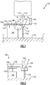
- Figure 2 schematically illustrates an enhanced view of a portion 190 of the EDM system 100 of Figure 1 .
- the zoomed in portion includes a component 160 being worked by the EDM system 100, and illustrates the machining wire 130 at an angle of greater than 25 degrees.
- the fixture 150 includes a slot (illustrated in Figures 3-4B ) of sufficient size to fit the wire guide 120. The slot allows the wire guide 120 to protrude partially into the fixture 150 during operation of the EDM system 100, thereby allowing for a taller wire guide 120, and a larger angle 132 of the machining wire 130 to be utilized.
- clamp connections such as clamp connections, key slots, multiple segments, etc.
- multiple segments such as clamp connections, key slots, multiple segments, etc.
- Figure 3 schematically illustrates an isometric view of a fixture 300 that could be used as the fixture 150 of Figures 1 and 2 .
- the fixture 300 includes a center portion 310 configured to rest on the top surface 144 of the fixed table 142.
- the fixture 300 includes four bolt holes 312, each of which corresponds to a bolt hole in the fixed table. Bolts are passed through the bolt holes 312 in the fixture 300 and the fixed table 142, thereby maintaining the fixture in position relative to the fixed table 142.
- Alternative fixtures can utilize alternative numbers and forms of fastener features to fasten the fixture 300 to the fixed table 142 (illustrated in Figures 1 and 2 ).
- Each section 320 extends radially outward from the center portion 310, with a mounting surface 322 of each section 320 being lower than a top surface 314 of the center portion 310.
- Each section 320 is separated from each adjacent section 320 via a slot 330.
- the slots 330 are sized to fit around the wire guide 120 (illustrated in Figure 1 ) and facilitate the splitting of the component being worked.
- Each of the sections 320 further includes two clamp features 324.
- the clamp features 324 are configured to mount clamps to the sections 320, and allow a clamping structure to maintain the position of the component being worked during the machining process.
- Each of the sections 320 has a substantially hook shaped cross-section (illustrated in Figure 4A ) with the body having the mounting surface 322 being connected to the center portion 310 via a trough, or valley, connection.
- one of the sections 320a includes a keying feature 326.
- the keying feature 326 is a radially inward protruding notch in the section 320a. In some examples the notch extends a full height of the section 320a. In alternative examples, the notch extends a partial height of the section 320a. In either case, the keying feature 326 is used to align the fixture 300, once a component has been mounted on the fixture 300, in order to ensure that the machining is begun and stopped at the correct position. In some examples, the keying feature 326 includes a tram slot. The tram slot clocks the fixture 300 to the machine. In this way, the controller knows the positions of the fixture 300 and part relative to the machine, allowing the machine to perform cuts in the correct positions.
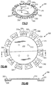
- Figures 4A and 4B illustrate the fixture 300 in greater detail, with Figure 4A illustrating a top view, and with Figure 4B illustrating a cross-sectional view of the fixture 300 drawn along cross-sectional view line A-A.
- each of the sections 320 extends for a set arc length 340 between two adjacent slots 330.
- the arc lengths 340 of the sections are inconsistent, and are specifically configured according to the segmentation parameters of a given component to be worked in conjunction with the fixture 300.
- each of the sections can be one of two different arc lengths. In alternative examples, any number of different arc lengths can be used.
- clocking pins 350 are also included on a subset of the sections 320.
- three of the sections 320 include clocking pins 350.
- the clocking pins 350 correspond to a clocking feature of the component being worked, and ensure that the component is placed on the fixture 300 in the correct orientation.
- Each of the clocking pins 350 is a nub that protrudes upward from the mounting surface 322.
- the clocking pins 350 are dispersed about the sections 320 such that the component to be worked can only interface with the fixture 300 in a single orientation. This ensures that the splits machined into the component occur in the correct location.
- alternative numbers and types of clocking features can be utilized in place of the clocking pins 350 described above.
- only a single section 320 includes a clocking pin 350.
- One of skill in the art, having the benefit of this disclosure, will understand that any specific number and configuration of clocking pins 350 can be utilized to accurately clock the part to the fixture 300.
- the sections 320 can be uniform in size and arc length 340.
- the clocking pins 350 can be evenly distributed about multiple sections 320, and the component can interface with the fixture 300 in multiple distinct orientations.
Landscapes
- Engineering & Computer Science (AREA)
- Mechanical Engineering (AREA)
- Physics & Mathematics (AREA)
- Thermal Sciences (AREA)
- General Engineering & Computer Science (AREA)
- Manufacturing & Machinery (AREA)
- Electrical Discharge Machining, Electrochemical Machining, And Combined Machining (AREA)
Abstract
Description
- The present disclosure relates generally to an apparatus for Electrical Discharge Machining (EDM Machining), and more specifically to a rotary table fixture for the same.
- Aircraft components, such as vane clusters, rotor clusters, and the like, are in some cases manufactured as an annular component. In order to properly assemble the turbine engine that the components are for, the full ring must be split into multiple distinct segments. The segments are then installed and reconnected in a manner that reconstructs the full ring within the turbine engine.
- In some examples, the aircraft component is split into segments using a machining process, such as electrical discharge machining (EDM). In one example system, an EDM machine utilizes a guide wire that machines into and through a component to split the component into segments.
- Certain configurations of components, and engine installation requirements, can dictate that the guide wire be angled relative to a line normal to a base surface of the EDM machine. Due to physical constraints, such as part size and EDM machine size, a typical EDM machine has a maximum angle at which the part can be cut, and a maximum clearance height of parts that can be cut. As a result of the physical constraints, EDM machines are limited in what size parts can be worked, and in what type of working can be done to the parts.
- In one exemplary embodiment an Electrical Discharge Machining (EDM Machining) machine includes a machine head, a wire guide, a machining wire extending from the wire guide to the machine head, a rotary table mounted to a first surface and a fixed table mounted to the rotary table, and a fixture mounted to the fixed table, the fixture including a mounting portion substantially circumscribing the fixture, the mounting portion further including a mounting surface, the mounting surface being closer to a first surface than an upper surface of the fixed table.
- In an exemplary embodiment of the above described EDM machine the mounting portion includes a plurality of radial slots disposed about the circumference of the fixture.
- In another exemplary embodiment of any of the above described EDM machines the mounting portion includes a plurality of sections, each of the sections being separated from an adjacent section by one of the radial slots and each of the sections including at least one fastener feature configured to mount a clamping device.
- In another exemplary embodiment of any of the above described EDM machines the at least one fastener feature configured to mount a clamping device comprises a pair of threaded holes.
- In another exemplary embodiment of any of the above described EDM machines at least one of the plurality of sections includes a key slot, the key slot being a radial insertion at an outer edge of the section.
- In another exemplary embodiment of any of the above described EDM machines the plurality of sections comprise sections of at least two distinct arc lengths.
- In another exemplary embodiment of any of the above described EDM machines the machining wire is disposed an angle greater than 25 degrees, the angle being drawn relative to a line normal to the first surface.
- In another exemplary embodiment of any of the above described EDM machines the angle is greater than or equal to 30 degrees.
- In another exemplary embodiment of any of the above described EDM machines the rotary table is mounted to the surface via a slide configured to allow the rotary table to slide in a linear direction.
- In another exemplary embodiment of any of the above described EDM machines the mounting surface includes a clocking feature protruding outward from the mounting surface.
- In one exemplary embodiment a fixture for an Electrical Discharge Machining (EDM) machine includes a center portion including a top face, relative to a gravitational direction, a mounting portion substantially circumscribing the circular center portion, the mounting portion including a mounting face aligned with the top face, the mounting face being lower than the top face, relative to the gravitational direction, and the mounting portion being connected to the center portion via a trough section having a hook shaped cross-section.
- In an exemplary embodiment of the above described fixture for an EDM machine the mounting portion is divided into a plurality of sections, each of the sections being separated from each adjacent section by a slot.
- In another exemplary embodiment of any of the above described fixtures for an EDM machine each section in the plurality of sections has an approximately identical arc length.
- In another exemplary embodiment of any of the above described fixtures for an EDM machine the plurality of sections includes at least a first plurality of sections having a first arc length, and a second plurality of sections having a second arc length, distinct form the first arc length.
- In another exemplary embodiment of any of the above described fixtures for an EDM machine a subset of the plurality of sections includes a clocking pin.
- In another exemplary embodiment of any of the above described fixtures for an EDM machine one of the plurality of sections includes a keying feature.
- In another exemplary embodiment of any of the above described fixtures for an EDM machine the keying feature is a radially inward protrusion into the section.
- In another exemplary embodiment of any of the above described fixtures for an EDM machine each of the slots is sized to receive a wire guide of an EDM machine.
- An exemplary method for mounting an annular component to an electrical discharge machining (EDM) machine includes mounting a fixture to a fixed table of an EDM machine such that a clearance between a mounting surface of the fixture and a machining head is larger than a clearance between a top surface of the fixed table and the machining head, and mounting the annular component to the mounting surface of the fixture.
- An example of the above described exemplary method for mounting an annular component to an electrical discharge machining (EDM) machine further includes orienting the annular component relative to the fixture via a clocking pin, and orienting the fixture relative to a machining head via at least one keying feature.
- These and other features of the present invention can be best understood from the following specification and drawings, the following of which is a brief description.
-
-
Figure 1 schematically illustrates an example electrical discharge machining (EDM) system. -
Figure 2 schematically illustrates an enhanced view of a portion of the EDM machining system ofFigure 1 . -
Figure 3 schematically illustrates an isometric view of an embodiment of a fixture for decreasing the physical constraints of the EDM machining system ofFigure 1 . -
Figure 4A schematically illustrates a top view of the fixture ofFigure 3 . -
Figure 4B schematically illustrates a cross-sectional view of the fixture ofFigure 3 . -
Figure 1 schematically illustrates an electrical discharge machining (EDM)system 100. Theexemplary EDM system 100 is suited for cutting annular turbine components into segments for assembly within a turbine engine. One of skill in the art, however, will recognize that alternative uses of the illustratedEDM system 100 will fall within the following scope. The general process of EDM machining is understood in the art. - The
EDM system 100 includes amachining head 110 that is connected to awire guide 120 via amachining wire 130. Thewire guide 120 is mounted to asurface 102 and themachining wire 130 extends upwards to themachining head 110 from thewire guide 120. A rotary table 140 is positioned on thesurface 102 adjacent to thewire guide 120. The rotary table 140 is mounted to a sliding component (not illustrated) that allows the rotary table 140 to slide into, and out of, themachining wire 130 during operation. A fixed table 142 is mounted to the top of the rotary table 140, and is configured to hold an annular component that is being split via theEDM system 100. To split an annular component, the component is mounted to the fixed table 142. Then the rotary table 140 is slid into themachining wire 130, and themachining wire 130 cuts the component using an electrical discharge. The rotary table 140 is slid back away from themachining wire 130, and rotated to a new position. This process is reiterated until a desired number of cuts is achieved. - A maximum height of the component being worked by the
EDM system 100 is defined by aclearance 146 between atop surface 144 of the fixed table 142 and abottom surface 112 of themachining head 110. - While the
wire guide 120 is located in a fixed position on thesurface 102, themachining head 110 is capable of moving in a plane parallel to thesurface 102. By moving themachining head 110, relative to thewire guide 120, themachining wire 130 can be angled resulting in an angled cut. Due to theparticular clearances 146 of the rotary table 140 and the height of thewire guide 120, anangle 132 of themachining wire 130 is, in some examples, limited to 25 degrees or lower. Theangle 132 is relative to a line normal to thesurface 102. - Certain annular components require a
larger clearance 146 of the fixed table 142, agreater angle 132 of themachining wire 130, or both, in order to make the desired cuts. In order to facilitate such components, afixture 150 is attached to the fixed table 142. Thefixture 150 extends beyond the outer circumference of the fixed table 142 and includes a hook shaped under hang portion. The under hang portion includes amounting surface 152. The annular component being worked can be mounted to themounting surface 152. Themounting surface 152 is connected to the center portion by a trough. Because themounting surface 152 is below thesurface 144 of the fixed table 142, apart clearance 154 of theEDM system 100 including thefixture 150 is larger than theclearance 146 without thefixture 150. This, in turn, allows components having a larger height to be worked. - Additionally, the
fixture 150 extends beyond the circumference of the fixed table 142. By mounting the component being worked beyond the outer circumference of the fixed table 142, thewire guide 120 can be taller, thereby allowing for agreater angle 132 on themachining wire 130, without increasing the movement of themachining head 110. In some examples, theangle 132 can be increased to greater than 25 degrees. In yet further examples, the angle can be increased to greater than or equal to 30 degrees. - The
fixture 150 is attached to the fixed table 142 via one or more fasteners. In the illustrated example ofFigure 1 , thefixture 150 includes a throughhole 148 that is aligned with a corresponding throughhole 148 in the fixed table 142. A bolt passes through the throughhole 148 and maintains thefixture 150 in position. In some examples, the throughhole 148 can be threaded, and the bolt is a threaded bolt. In other examples, the throughhole 148 can be smooth, and a bolt and nut configuration is used. One of skill in the art will recognize that alternative fastener means can be utilized to similar effect and hold thefixture 150 in position on the fixed table 142. - With continued reference to
Figure 1, Figure 2 schematically illustrates an enhanced view of aportion 190 of theEDM system 100 ofFigure 1 . In addition to theEDM system 100, the zoomed in portion includes acomponent 160 being worked by theEDM system 100, and illustrates themachining wire 130 at an angle of greater than 25 degrees. By lowering the mountingsurface 152 of thefixture 150, relative to thetop surface 144 of the fixed table 142, a corresponding increase in clearance is achieved, thereby allowing ataller component 160 to be worked by the machine. Further, thefixture 150 includes a slot (illustrated inFigures 3-4B ) of sufficient size to fit thewire guide 120. The slot allows thewire guide 120 to protrude partially into thefixture 150 during operation of theEDM system 100, thereby allowing for ataller wire guide 120, and alarger angle 132 of themachining wire 130 to be utilized. - Additional features, such as clamp connections, key slots, multiple segments, etc. can be incorporated in the
fixture 150, and are discussed below. - With continued reference to
Figures 1 and 2 ,Figure 3 schematically illustrates an isometric view of afixture 300 that could be used as thefixture 150 ofFigures 1 and 2 . Thefixture 300 includes acenter portion 310 configured to rest on thetop surface 144 of the fixed table 142. In the illustrated example, thefixture 300 includes fourbolt holes 312, each of which corresponds to a bolt hole in the fixed table. Bolts are passed through the bolt holes 312 in thefixture 300 and the fixed table 142, thereby maintaining the fixture in position relative to the fixed table 142. Alternative fixtures can utilize alternative numbers and forms of fastener features to fasten thefixture 300 to the fixed table 142 (illustrated inFigures 1 and 2 ). -
Multiple sections 320 extend radially outward from thecenter portion 310, with a mountingsurface 322 of eachsection 320 being lower than atop surface 314 of thecenter portion 310. Eachsection 320 is separated from eachadjacent section 320 via aslot 330. Theslots 330 are sized to fit around the wire guide 120 (illustrated inFigure 1 ) and facilitate the splitting of the component being worked. Each of thesections 320 further includes two clamp features 324. The clamp features 324 are configured to mount clamps to thesections 320, and allow a clamping structure to maintain the position of the component being worked during the machining process. - Each of the
sections 320 has a substantially hook shaped cross-section (illustrated inFigure 4A ) with the body having the mountingsurface 322 being connected to thecenter portion 310 via a trough, or valley, connection. - In the illustrated example of
Figure 3 , one of thesections 320a includes akeying feature 326. The keyingfeature 326 is a radially inward protruding notch in thesection 320a. In some examples the notch extends a full height of thesection 320a. In alternative examples, the notch extends a partial height of thesection 320a. In either case, the keyingfeature 326 is used to align thefixture 300, once a component has been mounted on thefixture 300, in order to ensure that the machining is begun and stopped at the correct position. In some examples, the keyingfeature 326 includes a tram slot. The tram slot clocks thefixture 300 to the machine. In this way, the controller knows the positions of thefixture 300 and part relative to the machine, allowing the machine to perform cuts in the correct positions. - With continued reference to
Figure 3 , and with like numerals indicating like elements,Figures 4A and 4B illustrate thefixture 300 in greater detail, withFigure 4A illustrating a top view, and withFigure 4B illustrating a cross-sectional view of thefixture 300 drawn along cross-sectional view line A-A. As can be seen inFigure 4A , each of thesections 320 extends for aset arc length 340 between twoadjacent slots 330. In the illustrated example, thearc lengths 340 of the sections are inconsistent, and are specifically configured according to the segmentation parameters of a given component to be worked in conjunction with thefixture 300. In some examples, each of the sections can be one of two different arc lengths. In alternative examples, any number of different arc lengths can be used. - Also included on a subset of the
sections 320 are clockingpins 350. In the illustrated example, three of thesections 320 include clocking pins 350. The clocking pins 350 correspond to a clocking feature of the component being worked, and ensure that the component is placed on thefixture 300 in the correct orientation. Each of the clocking pins 350, is a nub that protrudes upward from the mountingsurface 322. The clocking pins 350 are dispersed about thesections 320 such that the component to be worked can only interface with thefixture 300 in a single orientation. This ensures that the splits machined into the component occur in the correct location. In alternative examples, alternative numbers and types of clocking features can be utilized in place of the clocking pins 350 described above. In yet further alternate examples, only asingle section 320 includes aclocking pin 350. One of skill in the art, having the benefit of this disclosure, will understand that any specific number and configuration of clockingpins 350 can be utilized to accurately clock the part to thefixture 300. - In alternative examples, the
sections 320 can be uniform in size andarc length 340. In such an example, the clocking pins 350 can be evenly distributed aboutmultiple sections 320, and the component can interface with thefixture 300 in multiple distinct orientations. - While the EDM machining apparatus and fixtures described above are adapted for working a turbine engine component, one of skill in the art having the benefit of this disclosure will understand that the apparatus and concept described herein can be utilized in the machining and working of any part and is not limited to the working of aircraft engine parts or turbine parts.
- It is further understood that any of the above described concepts can be used alone or in combination with any or all of the other above described concepts. Although an embodiment of this invention has been disclosed, a worker of ordinary skill in this art would recognize that certain modifications would come within the scope of this invention. For that reason, the following claims should be studied to determine the true scope and content of this invention.
Claims (15)
- An Electrical Discharge Machining (EDM) machine (100) comprising:a machine head (110);a wire guide (120);a machining wire (130) extending from said wire guide (120) to said machine head (110);a rotary table (140) mounted to a first surface (102) and a fixed table (142) mounted to the rotary table (140); anda fixture (150;300) mounted to the fixed table (142), the fixture (150;300) including a mounting portion substantially circumscribing the fixture (150;300), the mounting portion further including a mounting surface (152;322), said mounting surface (152;322) being closer to the first surface (102) than an upper surface (144) of said fixed table (142).
- The EDM machine of claim 1, wherein the mounting portion includes a plurality of radial slots (330) disposed about the circumference of the fixture (150;300) and a plurality of sections (320), each of said sections (320) being separated from an adjacent section (320) by one of said radial slots (330) and each of said sections (320) including at least one fastener feature (324) configured to mount a clamping device.
- The EDM machine of claim 2, wherein the at least one fastener feature (324) configured to mount a clamping device comprises a pair of threaded holes (324).
- The EDM machine of claim 2 or 3, wherein at least one of said plurality of sections (320a) includes a key slot (326), the key slot (326) being a radial insertion at an outer edge of the section (320a).
- The EDM machine of claim 2, 3 or 4, wherein the plurality of sections (320) comprise sections of at least two distinct arc lengths (340).
- The EDM machine of any preceding claim, wherein the machining wire (130) is disposed an angle (132) greater than 25 degrees, the angle (132) being drawn relative to a line normal to the first surface (102).
- The EDM machine of claim 6, wherein the angle (132) is greater than or equal to 30 degrees.
- The EDM machine of any preceding claim, wherein the rotary table (140) is mounted to the first surface (102) via a slide configured to allow the rotary table (140) to slide in a linear direction.
- The EDM machine of any preceding claim, wherein said mounting surface (152;322) includes a clocking feature (350) protruding outward from said mounting surface (152;322).
- A fixture (150;300) for an Electrical Discharge Machining (EDM) machine, comprising:a center portion (310) including a top face (314), relative to a gravitational direction;a mounting portion substantially circumscribing the circular center portion (310), the mounting portion including a mounting face (152; 322) aligned with the top face (314);the mounting face (152;322) being lower than the top face (314), relative to the gravitational direction; andthe mounting portion being connected to the center portion (310) via a trough section having a hook shaped cross-section.
- The fixture of claim 10, wherein the mounting portion is divided into a plurality of sections (320), each of said sections (320) being separated from each adjacent section (320) by a slot (330), wherein, optionally, the slot (330) is sized to receive a wire guide (120) of an EDM machine (100).
- The fixture of claim 11, wherein said plurality of sections (320) includes at least a first plurality of sections having a first arc length (340), and a second plurality of sections having a second arc length (340), distinct form the first arc length (340).
- The fixture of claim 11 or 12, wherein a subset of said plurality of sections (320) includes a clocking pin (350).
- The fixture of claim 11, 12 or 13, wherein one of said plurality of sections (320a) includes a keying feature (326), wherein, optionally, the keying feature (326) is a radially inward protrusion into said section (320).
- A method for mounting an annular component (160) to an electrical discharge machining (EDM) machine (100) comprising:mounting a fixture (150;300) to a fixed table (142) of an EDM machine (100) such that a clearance (154) between a mounting surface (152;322) of the fixture (150;300) and a machining head (110) is larger than a clearance (146) between a top surface (144) of the fixed table (142) and the machining head (110);mounting the annular component (160) to the mounting surface (152;322) of the fixture (150;300);orienting the annular component (160) relative to the fixture (150;300) via a clocking pin (350); andorienting the fixture (150;300) relative to the machining head (110) via at least one keying feature (326).
Applications Claiming Priority (1)
| Application Number | Priority Date | Filing Date | Title |
|---|---|---|---|
| US14/995,448 US10272510B2 (en) | 2016-01-14 | 2016-01-14 | Electrical discharge machining apparatus |
Publications (3)
| Publication Number | Publication Date |
|---|---|
| EP3192606A1 true EP3192606A1 (en) | 2017-07-19 |
| EP3192606B1 EP3192606B1 (en) | 2021-03-03 |
| EP3192606B8 EP3192606B8 (en) | 2021-04-14 |
Family
ID=57796275
Family Applications (1)
| Application Number | Title | Priority Date | Filing Date |
|---|---|---|---|
| EP17151513.3A Active EP3192606B8 (en) | 2016-01-14 | 2017-01-13 | Electrical discharge machining apparatus and method |
Country Status (2)
| Country | Link |
|---|---|
| US (2) | US10272510B2 (en) |
| EP (1) | EP3192606B8 (en) |
Families Citing this family (2)
| Publication number | Priority date | Publication date | Assignee | Title |
|---|---|---|---|---|
| US10272510B2 (en) * | 2016-01-14 | 2019-04-30 | United Technologies Corporation | Electrical discharge machining apparatus |
| US11569172B2 (en) * | 2019-08-08 | 2023-01-31 | Taiwan Semiconductor Manufacturing Co., Ltd. | Semiconductor devices and methods of manufacture |
Citations (4)
| Publication number | Priority date | Publication date | Assignee | Title |
|---|---|---|---|---|
| DE4203656A1 (en) * | 1992-02-08 | 1993-08-12 | Abb Patent Gmbh | Wire electrode EDM machine for producing blade root slots in turbine discs - has wire electrode guided parallel to rotor axis on end of fork whose movement is programmed to follow desired slot profile |
| US20080000947A1 (en) * | 2006-06-19 | 2008-01-03 | Snecma | Part-holding device in a repairing method for a blade of a monobloc bladed disc in a turbo-machine |
| CN204248430U (en) * | 2014-09-25 | 2015-04-08 | 成都恒信创智科技有限公司 | A kind of blisk universal fixturing |
| CN103612129B (en) * | 2013-11-08 | 2015-12-09 | 沈阳黎明航空发动机(集团)有限责任公司 | A kind of self adaptation supports resistance to deformation fixture |
Family Cites Families (112)
| Publication number | Priority date | Publication date | Assignee | Title |
|---|---|---|---|---|
| US2413003A (en) * | 1944-12-11 | 1946-12-24 | Standard Telephones Cables Ltd | High-frequency baking apparatus |
| US2678719A (en) * | 1949-07-20 | 1954-05-18 | Udylite Corp | Rotary table structure |
| US3095499A (en) * | 1961-06-01 | 1963-06-25 | Raytheon Co | Continuous dial feed electric welding apparatus |
| US3570704A (en) * | 1966-07-07 | 1971-03-16 | Benjamin Juan Roson | Pressure cookers |
| US3612810A (en) * | 1969-12-23 | 1971-10-12 | Oconnor Thomas John | Movable dielectric tank for electroerosive machines |
| US3700228A (en) * | 1970-09-25 | 1972-10-24 | Robert E Peale | Adjustable axis work support |
| US3802046A (en) * | 1972-01-27 | 1974-04-09 | Chromalloy American Corp | Method of making or reconditioning a turbine-nozzle or the like assembly |
| US4029929A (en) * | 1975-01-27 | 1977-06-14 | Colt Industries Operating Corporation | Electrical discharge machining device for cutting with wire electrode |
| US4420671A (en) * | 1981-09-14 | 1983-12-13 | Ateliers Des Charmilles S.A. | Helicoidal guide for wire electrode of an EDM apparatus |
| US4499362A (en) * | 1983-06-29 | 1985-02-12 | Philip Morris Incorporated | Rotary beam chopper with continuously variable duty cycle |
| US4729372A (en) * | 1983-11-17 | 1988-03-08 | Lri L.P. | Apparatus for performing ophthalmic laser surgery |
| CH656082A5 (en) * | 1984-04-18 | 1986-06-13 | Charmilles Technologies | MACHINE FOR ELECTROEROSION CUTTING WITH IMMOBILIZATION OF THE FALL. |
| JPS61109614A (en) * | 1984-10-30 | 1986-05-28 | Amada Co Ltd | Wire cut discharge machining unit |
| CH669350A5 (en) | 1984-12-05 | 1989-03-15 | Agie Ag Ind Elektronik | |
| US4841126A (en) | 1987-12-28 | 1989-06-20 | Mcwilliams Machinery Sales, Division Of Bridgeport Machines Inc. | Rotary table wire EDM machine |
| US5120927A (en) * | 1988-06-03 | 1992-06-09 | Insite Peripherals, Inc. | High track density media with optical servo tracks and method and apparatus for inscribing the tracks on the media |
| DE3990961C2 (en) * | 1988-08-19 | 1995-09-14 | Mitsubishi Electric Corp | Wire breakage restoration of wire electric discharge machining |
| US5410117A (en) * | 1989-01-13 | 1995-04-25 | Charmilles Technologies S.A. | Device and control process for EDM machining with an electrode-wire |
| EP0383370B1 (en) * | 1989-01-13 | 1995-07-26 | Charmilles Technologies S.A. | Control and method for electroerosion wire cutting avoiding wire breakage |
| JP2518075B2 (en) * | 1989-04-28 | 1996-07-24 | 三菱電機株式会社 | Wire electrode supply device for wire electric discharge machine |
| US5225650A (en) * | 1989-07-14 | 1993-07-06 | Maho Aktiengesellschaft | Process and device for the manufacture of cavities in workpieces through laser beams |
| JPH0694090B2 (en) * | 1989-09-05 | 1994-11-24 | 三菱電機株式会社 | Wire electric discharge machining method and apparatus |
| JP2536223B2 (en) * | 1990-03-28 | 1996-09-18 | 三菱電機株式会社 | Contact detection device |
| JPH04141322A (en) * | 1990-09-28 | 1992-05-14 | Mitsubishi Electric Corp | Repair method for wire electrode disconnection of wire electric discharging work device |
| DE4116868C2 (en) * | 1991-05-23 | 1995-07-27 | Agie Ag Ind Elektronik | Process for machining workpieces, in particular for EDM machining of workpieces using a wire |
| US5756953A (en) * | 1991-05-31 | 1998-05-26 | Charmilles Technologies Sa | Electroerosion machine for wire cutting a stationary workpiece |
| US5326953A (en) * | 1991-10-28 | 1994-07-05 | Mitsubishi Denki Kabushiki Kaisha | Wire electrode feeder for wirecut electrical discharge machine |
| US5315087A (en) * | 1992-03-02 | 1994-05-24 | Mitsubishi Denki Kabushiki Kaisha | Wirecut electrical discharge machine utilizing silicon powder suspended in a dielectric material |
| JP3237895B2 (en) * | 1992-04-30 | 2001-12-10 | ブラザー工業株式会社 | Wire electric discharge machine |
| JP3258368B2 (en) * | 1992-05-01 | 2002-02-18 | ブラザー工業株式会社 | Wire electric discharge machine |
| US5544726A (en) * | 1994-09-06 | 1996-08-13 | Ford Motor Company | Brake rotor with flow through ventilation |
| US5893984A (en) * | 1995-10-27 | 1999-04-13 | General Electric Company | High aspect ratio EDM electrode assembly |
| DE59705344D1 (en) * | 1996-06-17 | 2001-12-20 | Certa Ag Reinach | Clamping device and device for position-defined clamping of a tool or workpiece |
| US5751436A (en) * | 1996-12-23 | 1998-05-12 | Rocky Mountain Instrument Company | Method and apparatus for cylindrical coordinate laser engraving |
| JPH11263415A (en) * | 1998-01-08 | 1999-09-28 | Xerox Corp | Manufacture of endless seam belt and manufacturing device |
| US6036198A (en) * | 1999-04-01 | 2000-03-14 | Kramer; Hy | Coupling for attaching a tool to a chuck |
| US6326579B1 (en) | 1999-08-05 | 2001-12-04 | General Electric Company | Methods and apparatus for machining a work piece |
| JP4140174B2 (en) * | 2000-06-28 | 2008-08-27 | ブラザー工業株式会社 | Control device and control method of wire electric discharge machine, and storage medium |
| US6734401B2 (en) * | 2000-06-28 | 2004-05-11 | 3M Innovative Properties Company | Enhanced sample processing devices, systems and methods |
| FR2812918B1 (en) * | 2000-08-11 | 2003-03-07 | Valeo | IMPROVEMENT TO A DIAPHRAGM CLUTCH MECHANISM FOR A MOTOR VEHICLE ENGINE |
| JP3815436B2 (en) * | 2000-09-28 | 2006-08-30 | 三菱電機株式会社 | Wire electrical discharge machine |
| WO2002039446A2 (en) * | 2000-11-09 | 2002-05-16 | Burstein Technologies, Inc. | Disc drive system and methods for use with bio-discs |
| US7380645B1 (en) * | 2000-11-16 | 2008-06-03 | Cwd, Llc | Aerodynamic standoffs to air cool disc type auto brake rotors |
| US6384364B1 (en) | 2000-12-21 | 2002-05-07 | General Electric Company | Method of aligning electrode in multiple-axis EDM drilling |
| KR100537769B1 (en) * | 2001-01-09 | 2005-12-19 | 미쓰비시덴키 가부시키가이샤 | Electrical discharge machining apparatus |
| DE10196821T5 (en) * | 2001-02-14 | 2004-04-15 | Mitsubishi Denki K.K. | Wire EDM method and device |
| WO2002102538A1 (en) * | 2001-06-15 | 2002-12-27 | Mitsubishi Denki Kabushiki Kaisha | Wire electric-discharge machining method and device |
| EP1459828B1 (en) * | 2001-11-27 | 2014-03-26 | Mitsubishi Denki Kabushiki Kaisha | Method of operating a wire electrical discharge machining apparatus |
| AU2002219551A1 (en) * | 2001-12-28 | 2003-07-30 | Hitachi High-Technologies Corporation | Extractor, chemical analyzer, and chemical analyzing method |
| WO2003093836A1 (en) * | 2002-04-30 | 2003-11-13 | Arkray, Inc. | Analysis instrument, sample analysis method and analysis device using the instrument, and method of forming opening in the instrument |
| US7420144B2 (en) * | 2002-07-23 | 2008-09-02 | Magtec Llc | Controlled torque magnetic heat generation |
| US7083974B2 (en) * | 2002-07-12 | 2006-08-01 | Applera Corporation | Rotatable sample disk and method of loading a sample disk |
| US6717094B2 (en) * | 2002-07-22 | 2004-04-06 | Edward L. Beaumont | Electrical discharge machine and methods of establishing zero set conditions for operation thereof |
| JP4119786B2 (en) | 2003-05-21 | 2008-07-16 | 富士フイルム株式会社 | Recording tape cartridge |
| US20040241048A1 (en) * | 2003-05-30 | 2004-12-02 | Applera Corporation | Thermal cycling apparatus and method for providing thermal uniformity |
| JP4490655B2 (en) * | 2003-06-17 | 2010-06-30 | 株式会社エレニックス | Thin hole electric discharge machining apparatus, die-sculpting / thin hole combined electric discharge machining apparatus and die-cutting / thin hole combined electric discharge machining method using the same apparatus |
| KR100645034B1 (en) * | 2004-03-26 | 2006-11-13 | 마키노 밀링 머신 주식회사 | Method and apparatus for cutting, and rib electrodes for electro-discharge machining |
| FR2868519B1 (en) * | 2004-03-30 | 2006-06-16 | Christian Muller | THERMAL GENERATOR WITH MAGNETO-CALORIC MATERIAL AND METHOD OF GENERATING THERMIES |
| US7568560B2 (en) * | 2004-06-03 | 2009-08-04 | Warren Lin | Center mount two piece brake rotor |
| US6930272B1 (en) | 2004-07-06 | 2005-08-16 | Michael P. Limano | Vise for holding a workpiece on an EDM machine |
| US20060086579A1 (en) * | 2004-10-21 | 2006-04-27 | Gerber Kraig E | Disc brake rotor |
| PL1666195T3 (en) * | 2004-12-01 | 2007-10-31 | Erowa Ag | Pallet clamping device with a damping element |
| US7507575B2 (en) * | 2005-04-01 | 2009-03-24 | 3M Innovative Properties Company | Multiplex fluorescence detection device having removable optical modules |
| ES2364253T3 (en) * | 2005-05-20 | 2011-08-29 | Dytech - Dynamic Fluid Technologies S.P.A. | A METHOD FOR THE MANUFACTURE OF A FILLING NECK FOR A FUEL TANK, AND CORRESPONDING EQUIPMENT. |
| PT1724144E (en) * | 2005-05-20 | 2012-10-09 | Dytech Dynamic Fluid Tech Spa | A method for welding the filler neck of the fuel tank of a motor vehicle |
| US7323660B2 (en) * | 2005-07-05 | 2008-01-29 | 3M Innovative Properties Company | Modular sample processing apparatus kits and modules |
| USD564667S1 (en) * | 2005-07-05 | 2008-03-18 | 3M Innovative Properties Company | Rotatable sample processing disk |
| WO2007012056A2 (en) * | 2005-07-19 | 2007-01-25 | Hansen Thomas C | Tangential manufacturing system |
| JP4530933B2 (en) * | 2005-07-21 | 2010-08-25 | 大日本スクリーン製造株式会社 | Substrate heat treatment equipment |
| CN101309770B (en) * | 2005-11-16 | 2010-08-04 | 三菱电机株式会社 | Wire discharge machining method, semiconductor wafer manufacturing method, and solar cell cell manufacturing method |
| US7214901B1 (en) * | 2006-01-17 | 2007-05-08 | General Electric Company | Duplex electrical discharge machining |
| ATE417699T1 (en) * | 2006-04-27 | 2009-01-15 | 3R Syst Int Ab | CLAMPING DEVICE WITH DEVICE FOR MEASURING THE DISTANCE BETWEEN A CHUCK AND A TOOL OR WORKPIECE HOLDER |
| TW200741409A (en) * | 2006-04-28 | 2007-11-01 | Coretronic Corp | Rotary object pattern manufacturing system and method thereof |
| US7605339B1 (en) | 2006-11-21 | 2009-10-20 | Moberg Clifford A | Methods of forming an annular undercut |
| US20080277383A1 (en) * | 2007-05-11 | 2008-11-13 | Michael Sandlin | Apparatus for removing debris from the cutting gap of a work piece on a wire electronic discharge machine and method therefor |
| CN101332526B (en) * | 2007-06-29 | 2010-06-09 | 通用电气公司 | Electro-eroding rough machining method |
| US8288675B2 (en) | 2007-12-28 | 2012-10-16 | Depuy Products, Inc. | Method and apparatus for fabricating an orthopaedic prosthetic component |
| US8461482B2 (en) * | 2008-06-18 | 2013-06-11 | Electro Scientific Industries, Inc. | Pre-process stress loading components for post-process warp control |
| CH699231B1 (en) * | 2008-07-22 | 2012-03-30 | Erowa Ag | Tensioning device. |
| KR101020548B1 (en) * | 2008-09-03 | 2011-03-09 | 주식회사 데크 | Mounting unit and brake disc with this mounting unit |
| US7861832B2 (en) * | 2008-09-12 | 2011-01-04 | Gm Global Technology Operations, Inc. | Thermally accommodating interconnection for cast-in-place components |
| JP2010216649A (en) * | 2009-02-19 | 2010-09-30 | Advics Co Ltd | Ventilated type disc rotor |
| WO2010108930A2 (en) * | 2009-03-23 | 2010-09-30 | Engin Hasan Hueseyin | Laboratory type quick film drying oven |
| US20100243643A1 (en) * | 2009-03-30 | 2010-09-30 | Cesano Mariolino | Device and method for performing a localized induction hardening treatment on mechanical components, specifically thrust blocks for large-sized rolling bearings |
| CN101850448A (en) | 2009-03-31 | 2010-10-06 | 南通国盛机电集团有限公司 | Adjusting mechanism of shaping electric discharge machine workbench |
| US8109201B2 (en) * | 2009-04-01 | 2012-02-07 | Hamilton Beach Brands, Inc. | Kitchen appliance for heating foodstuff |
| US8378252B2 (en) * | 2009-05-29 | 2013-02-19 | Electro Scientific Industries, Inc. | Method and apparatus for hybrid resolution feedback of a motion stage |
| JP5632924B2 (en) * | 2009-11-03 | 2014-11-26 | ザ セクレタリー,デパートメント オブ アトミック エナジー,ガヴァメント,オブ インディア | Niobium-based superconducting radio frequency (SCRF) cavity with niobium parts joined by laser welding, method for manufacturing the same, and apparatus for manufacturing the same |
| US8834792B2 (en) * | 2009-11-13 | 2014-09-16 | 3M Innovative Properties Company | Systems for processing sample processing devices |
| US8950556B2 (en) * | 2011-03-31 | 2015-02-10 | Gunite Corporation | Disk brake hub assembly |
| US9452482B2 (en) * | 2011-04-19 | 2016-09-27 | Kurashiki System Design Co., Ltd. | Electrical discharge machine |
| US9168523B2 (en) * | 2011-05-18 | 2015-10-27 | 3M Innovative Properties Company | Systems and methods for detecting the presence of a selected volume of material in a sample processing device |
| JP5426733B2 (en) * | 2012-07-10 | 2014-02-26 | ファナック株式会社 | Wire electric discharge machine and automatic programming device for wire electric discharge machine |
| JP5925900B2 (en) * | 2012-09-07 | 2016-05-25 | 株式会社牧野フライス製作所 | Elevating machine lifting device for electric discharge machine |
| KR101384483B1 (en) * | 2013-01-28 | 2014-04-10 | 이영희 | Cookware lid with pyrolysis function |
| JP2014200864A (en) * | 2013-04-02 | 2014-10-27 | ファナック株式会社 | Wire electric discharge machine having wire electrode tension control function |
| WO2014167724A1 (en) * | 2013-04-12 | 2014-10-16 | 三菱電機株式会社 | Wire-suctioning device and wire-collecting device |
| US9188180B2 (en) * | 2013-05-13 | 2015-11-17 | GM Global Technology Operations LLC | Brake rotor and method of manufacturing the same |
| JP5766755B2 (en) * | 2013-08-16 | 2015-08-19 | ファナック株式会社 | In a wire electric discharge machine, a method for correcting the rotation touch of a rotary tool attached to a rotary shaft, and a wire electric discharge machine having a correction function |
| JP5752196B2 (en) * | 2013-09-03 | 2015-07-22 | ファナック株式会社 | Program creation device for wire electric discharge machine |
| JP5788468B2 (en) * | 2013-11-28 | 2015-09-30 | ファナック株式会社 | Wire electrical discharge machine with function to suppress wear of drive parts |
| JP5887376B2 (en) * | 2014-04-09 | 2016-03-16 | ファナック株式会社 | Electric discharge machine with rotating shaft |
| JP6219785B2 (en) * | 2014-06-23 | 2017-10-25 | ファナック株式会社 | Wire electric discharge machine equipped with disconnection repair means |
| JP5977290B2 (en) * | 2014-07-30 | 2016-08-24 | ファナック株式会社 | Wire electrical discharge machine with function for preventing mis-machining |
| EP3023186A1 (en) * | 2014-11-19 | 2016-05-25 | Fanuc Corporation | Wire electric discharge machine having corner shape correcting function |
| US9604330B2 (en) * | 2015-03-12 | 2017-03-28 | Jia Sin Precision Co., Ltd. | Positioning block structure for machining fixture |
| JP6588247B2 (en) * | 2015-06-18 | 2019-10-09 | 株式会社ディスコ | Multi wire saw |
| US10272510B2 (en) * | 2016-01-14 | 2019-04-30 | United Technologies Corporation | Electrical discharge machining apparatus |
| JP6484286B2 (en) * | 2017-05-12 | 2019-03-13 | ファナック株式会社 | Wire electric discharge machine and display method |
| KR101994113B1 (en) * | 2017-10-11 | 2019-07-01 | 경창산업주식회사 | Vented Brake Disc |
| US10967450B2 (en) * | 2018-05-04 | 2021-04-06 | Infineon Technologies Ag | Slicing SiC material by wire electrical discharge machining |
| US11235403B2 (en) * | 2019-10-04 | 2022-02-01 | Pratt & Whitney Canada Corp. | Electrical discharge machining electrodes and associated methods |
-
2016
- 2016-01-14 US US14/995,448 patent/US10272510B2/en active Active
-
2017
- 2017-01-13 EP EP17151513.3A patent/EP3192606B8/en active Active
-
2019
- 2019-03-18 US US16/356,292 patent/US11484958B2/en active Active
Patent Citations (4)
| Publication number | Priority date | Publication date | Assignee | Title |
|---|---|---|---|---|
| DE4203656A1 (en) * | 1992-02-08 | 1993-08-12 | Abb Patent Gmbh | Wire electrode EDM machine for producing blade root slots in turbine discs - has wire electrode guided parallel to rotor axis on end of fork whose movement is programmed to follow desired slot profile |
| US20080000947A1 (en) * | 2006-06-19 | 2008-01-03 | Snecma | Part-holding device in a repairing method for a blade of a monobloc bladed disc in a turbo-machine |
| CN103612129B (en) * | 2013-11-08 | 2015-12-09 | 沈阳黎明航空发动机(集团)有限责任公司 | A kind of self adaptation supports resistance to deformation fixture |
| CN204248430U (en) * | 2014-09-25 | 2015-04-08 | 成都恒信创智科技有限公司 | A kind of blisk universal fixturing |
Also Published As
| Publication number | Publication date |
|---|---|
| US20200023449A1 (en) | 2020-01-23 |
| US11484958B2 (en) | 2022-11-01 |
| US20170203376A1 (en) | 2017-07-20 |
| EP3192606B8 (en) | 2021-04-14 |
| EP3192606B1 (en) | 2021-03-03 |
| US10272510B2 (en) | 2019-04-30 |
Similar Documents
| Publication | Publication Date | Title |
|---|---|---|
| US9327374B1 (en) | CNC fixture | |
| US11484958B2 (en) | Electrical discharge machining apparatus | |
| US8794587B2 (en) | Mounting apparatus | |
| KR101711780B1 (en) | Lifting tool for rotary shaft and lifting method for rotary shaft | |
| CN104308608A (en) | Fixture for milling key groove of long shaft | |
| CN110524069A (en) | A kind of processing inclined position guiding device | |
| SE518806C2 (en) | Method and apparatus for producing a stator or rotor component | |
| CN105351016A (en) | Methods and apparatus to facilitate turbine casing assembly | |
| US5183244A (en) | Blade assembling | |
| US9828878B2 (en) | Method and apparatus for supporting and aligning diaphragms in turbomachines | |
| CN105793523A (en) | Balanced turbine engine portion and turbine engine | |
| US10378382B2 (en) | Bolt fall-out preventing structure | |
| CN201483268U (en) | fixture | |
| CN208322772U (en) | A kind of frock clamp for annular gasket batch punching | |
| CN112091340B (en) | Machining method and clamp for slicing spring | |
| CN113953814B (en) | Mounting tool and mounting method for supporting plate nut | |
| US20160025012A1 (en) | Method and apparatus for improved turbine bellyband rotor seal machining, installation and life | |
| WO1991012931A1 (en) | Blade assembling | |
| CN104191272A (en) | Drilling positioning fixture for drilling flange disc mounting hole in multi-stage pump body | |
| CN106825720A (en) | It is a kind of for cutter spacing can quick regulation hydraulic clamping system | |
| CN205629479U (en) | Processing equipment | |
| CN223876226U (en) | Screw thread blade convenient to it is fixed | |
| RU158311U1 (en) | AXIAL FAN BLADE FASTENING ASSEMBLY | |
| CN209223616U (en) | A kind of fixed processing structure of receded disk impeller | |
| EP3895839A1 (en) | Method and mobile workpiece fixture for producing a curvic coupling |
Legal Events
| Date | Code | Title | Description |
|---|---|---|---|
| PUAI | Public reference made under article 153(3) epc to a published international application that has entered the european phase |
Free format text: ORIGINAL CODE: 0009012 |
|
| STAA | Information on the status of an ep patent application or granted ep patent |
Free format text: STATUS: THE APPLICATION HAS BEEN PUBLISHED |
|
| AK | Designated contracting states |
Kind code of ref document: A1 Designated state(s): AL AT BE BG CH CY CZ DE DK EE ES FI FR GB GR HR HU IE IS IT LI LT LU LV MC MK MT NL NO PL PT RO RS SE SI SK SM TR |
|
| AX | Request for extension of the european patent |
Extension state: BA ME |
|
| STAA | Information on the status of an ep patent application or granted ep patent |
Free format text: STATUS: REQUEST FOR EXAMINATION WAS MADE |
|
| 17P | Request for examination filed |
Effective date: 20180119 |
|
| RBV | Designated contracting states (corrected) |
Designated state(s): AL AT BE BG CH CY CZ DE DK EE ES FI FR GB GR HR HU IE IS IT LI LT LU LV MC MK MT NL NO PL PT RO RS SE SI SK SM TR |
|
| RIC1 | Information provided on ipc code assigned before grant |
Ipc: B23H 7/06 20060101ALN20200526BHEP Ipc: B23H 11/00 20060101AFI20200526BHEP Ipc: B23H 9/10 20060101ALI20200526BHEP Ipc: B23Q 3/06 20060101ALI20200526BHEP |
|
| RIC1 | Information provided on ipc code assigned before grant |
Ipc: B23H 7/06 20060101ALN20200608BHEP Ipc: B23H 9/10 20060101ALI20200608BHEP Ipc: B23Q 3/06 20060101ALI20200608BHEP Ipc: B23H 11/00 20060101AFI20200608BHEP |
|
| GRAP | Despatch of communication of intention to grant a patent |
Free format text: ORIGINAL CODE: EPIDOSNIGR1 |
|
| STAA | Information on the status of an ep patent application or granted ep patent |
Free format text: STATUS: GRANT OF PATENT IS INTENDED |
|
| RIC1 | Information provided on ipc code assigned before grant |
Ipc: B23Q 3/06 20060101ALI20200709BHEP Ipc: B23H 7/06 20060101ALN20200709BHEP Ipc: B23H 9/10 20060101ALI20200709BHEP Ipc: B23H 11/00 20060101AFI20200709BHEP |
|
| INTG | Intention to grant announced |
Effective date: 20200731 |
|
| GRAS | Grant fee paid |
Free format text: ORIGINAL CODE: EPIDOSNIGR3 |
|
| GRAA | (expected) grant |
Free format text: ORIGINAL CODE: 0009210 |
|
| STAA | Information on the status of an ep patent application or granted ep patent |
Free format text: STATUS: THE PATENT HAS BEEN GRANTED |
|
| AK | Designated contracting states |
Kind code of ref document: B1 Designated state(s): AL AT BE BG CH CY CZ DE DK EE ES FI FR GB GR HR HU IE IS IT LI LT LU LV MC MK MT NL NO PL PT RO RS SE SI SK SM TR |
|
| REG | Reference to a national code |
Ref country code: GB Ref legal event code: FG4D |
|
| REG | Reference to a national code |
Ref country code: DE Ref legal event code: R081 Ref document number: 602017033623 Country of ref document: DE Owner name: RAYTHEON TECHNOLOGIES CORPORATION, FARMINGTON, US Free format text: FORMER OWNER: UNITED TECHNOLOGIES CORPORATION, FARMINGTON, CONN., US Ref country code: DE Ref legal event code: R081 Ref document number: 602017033623 Country of ref document: DE Owner name: RTX CORPORATION (N.D.GES.D. STAATES DELAWARE),, US Free format text: FORMER OWNER: UNITED TECHNOLOGIES CORPORATION, FARMINGTON, CONN., US |
|
| REG | Reference to a national code |
Ref country code: AT Ref legal event code: REF Ref document number: 1366665 Country of ref document: AT Kind code of ref document: T Effective date: 20210315 Ref country code: CH Ref legal event code: EP |
|
| RAP2 | Party data changed (patent owner data changed or rights of a patent transferred) |
Owner name: RAYTHEON TECHNOLOGIES CORPORATION |
|
| REG | Reference to a national code |
Ref country code: DE Ref legal event code: R096 Ref document number: 602017033623 Country of ref document: DE |
|
| REG | Reference to a national code |
Ref country code: CH Ref legal event code: PK Free format text: BERICHTIGUNG B8 Ref country code: IE Ref legal event code: FG4D |
|
| REG | Reference to a national code |
Ref country code: LT Ref legal event code: MG9D |
|
| PG25 | Lapsed in a contracting state [announced via postgrant information from national office to epo] |
Ref country code: LT Free format text: LAPSE BECAUSE OF FAILURE TO SUBMIT A TRANSLATION OF THE DESCRIPTION OR TO PAY THE FEE WITHIN THE PRESCRIBED TIME-LIMIT Effective date: 20210303 Ref country code: BG Free format text: LAPSE BECAUSE OF FAILURE TO SUBMIT A TRANSLATION OF THE DESCRIPTION OR TO PAY THE FEE WITHIN THE PRESCRIBED TIME-LIMIT Effective date: 20210603 Ref country code: FI Free format text: LAPSE BECAUSE OF FAILURE TO SUBMIT A TRANSLATION OF THE DESCRIPTION OR TO PAY THE FEE WITHIN THE PRESCRIBED TIME-LIMIT Effective date: 20210303 Ref country code: GR Free format text: LAPSE BECAUSE OF FAILURE TO SUBMIT A TRANSLATION OF THE DESCRIPTION OR TO PAY THE FEE WITHIN THE PRESCRIBED TIME-LIMIT Effective date: 20210604 Ref country code: HR Free format text: LAPSE BECAUSE OF FAILURE TO SUBMIT A TRANSLATION OF THE DESCRIPTION OR TO PAY THE FEE WITHIN THE PRESCRIBED TIME-LIMIT Effective date: 20210303 Ref country code: NO Free format text: LAPSE BECAUSE OF FAILURE TO SUBMIT A TRANSLATION OF THE DESCRIPTION OR TO PAY THE FEE WITHIN THE PRESCRIBED TIME-LIMIT Effective date: 20210603 |
|
| REG | Reference to a national code |
Ref country code: NL Ref legal event code: MP Effective date: 20210303 |
|
| REG | Reference to a national code |
Ref country code: AT Ref legal event code: MK05 Ref document number: 1366665 Country of ref document: AT Kind code of ref document: T Effective date: 20210303 |
|
| PG25 | Lapsed in a contracting state [announced via postgrant information from national office to epo] |
Ref country code: SE Free format text: LAPSE BECAUSE OF FAILURE TO SUBMIT A TRANSLATION OF THE DESCRIPTION OR TO PAY THE FEE WITHIN THE PRESCRIBED TIME-LIMIT Effective date: 20210303 Ref country code: LV Free format text: LAPSE BECAUSE OF FAILURE TO SUBMIT A TRANSLATION OF THE DESCRIPTION OR TO PAY THE FEE WITHIN THE PRESCRIBED TIME-LIMIT Effective date: 20210303 Ref country code: PL Free format text: LAPSE BECAUSE OF FAILURE TO SUBMIT A TRANSLATION OF THE DESCRIPTION OR TO PAY THE FEE WITHIN THE PRESCRIBED TIME-LIMIT Effective date: 20210303 Ref country code: RS Free format text: LAPSE BECAUSE OF FAILURE TO SUBMIT A TRANSLATION OF THE DESCRIPTION OR TO PAY THE FEE WITHIN THE PRESCRIBED TIME-LIMIT Effective date: 20210303 |
|
| PG25 | Lapsed in a contracting state [announced via postgrant information from national office to epo] |
Ref country code: NL Free format text: LAPSE BECAUSE OF FAILURE TO SUBMIT A TRANSLATION OF THE DESCRIPTION OR TO PAY THE FEE WITHIN THE PRESCRIBED TIME-LIMIT Effective date: 20210303 |
|
| PG25 | Lapsed in a contracting state [announced via postgrant information from national office to epo] |
Ref country code: SM Free format text: LAPSE BECAUSE OF FAILURE TO SUBMIT A TRANSLATION OF THE DESCRIPTION OR TO PAY THE FEE WITHIN THE PRESCRIBED TIME-LIMIT Effective date: 20210303 Ref country code: AT Free format text: LAPSE BECAUSE OF FAILURE TO SUBMIT A TRANSLATION OF THE DESCRIPTION OR TO PAY THE FEE WITHIN THE PRESCRIBED TIME-LIMIT Effective date: 20210303 Ref country code: EE Free format text: LAPSE BECAUSE OF FAILURE TO SUBMIT A TRANSLATION OF THE DESCRIPTION OR TO PAY THE FEE WITHIN THE PRESCRIBED TIME-LIMIT Effective date: 20210303 Ref country code: CZ Free format text: LAPSE BECAUSE OF FAILURE TO SUBMIT A TRANSLATION OF THE DESCRIPTION OR TO PAY THE FEE WITHIN THE PRESCRIBED TIME-LIMIT Effective date: 20210303 |
|
| PG25 | Lapsed in a contracting state [announced via postgrant information from national office to epo] |
Ref country code: RO Free format text: LAPSE BECAUSE OF FAILURE TO SUBMIT A TRANSLATION OF THE DESCRIPTION OR TO PAY THE FEE WITHIN THE PRESCRIBED TIME-LIMIT Effective date: 20210303 Ref country code: SK Free format text: LAPSE BECAUSE OF FAILURE TO SUBMIT A TRANSLATION OF THE DESCRIPTION OR TO PAY THE FEE WITHIN THE PRESCRIBED TIME-LIMIT Effective date: 20210303 Ref country code: PT Free format text: LAPSE BECAUSE OF FAILURE TO SUBMIT A TRANSLATION OF THE DESCRIPTION OR TO PAY THE FEE WITHIN THE PRESCRIBED TIME-LIMIT Effective date: 20210705 Ref country code: IS Free format text: LAPSE BECAUSE OF FAILURE TO SUBMIT A TRANSLATION OF THE DESCRIPTION OR TO PAY THE FEE WITHIN THE PRESCRIBED TIME-LIMIT Effective date: 20210703 |
|
| REG | Reference to a national code |
Ref country code: DE Ref legal event code: R097 Ref document number: 602017033623 Country of ref document: DE |
|
| PLBE | No opposition filed within time limit |
Free format text: ORIGINAL CODE: 0009261 |
|
| STAA | Information on the status of an ep patent application or granted ep patent |
Free format text: STATUS: NO OPPOSITION FILED WITHIN TIME LIMIT |
|
| PG25 | Lapsed in a contracting state [announced via postgrant information from national office to epo] |
Ref country code: AL Free format text: LAPSE BECAUSE OF FAILURE TO SUBMIT A TRANSLATION OF THE DESCRIPTION OR TO PAY THE FEE WITHIN THE PRESCRIBED TIME-LIMIT Effective date: 20210303 Ref country code: DK Free format text: LAPSE BECAUSE OF FAILURE TO SUBMIT A TRANSLATION OF THE DESCRIPTION OR TO PAY THE FEE WITHIN THE PRESCRIBED TIME-LIMIT Effective date: 20210303 Ref country code: ES Free format text: LAPSE BECAUSE OF FAILURE TO SUBMIT A TRANSLATION OF THE DESCRIPTION OR TO PAY THE FEE WITHIN THE PRESCRIBED TIME-LIMIT Effective date: 20210303 |
|
| 26N | No opposition filed |
Effective date: 20211206 |
|
| PG25 | Lapsed in a contracting state [announced via postgrant information from national office to epo] |
Ref country code: SI Free format text: LAPSE BECAUSE OF FAILURE TO SUBMIT A TRANSLATION OF THE DESCRIPTION OR TO PAY THE FEE WITHIN THE PRESCRIBED TIME-LIMIT Effective date: 20210303 |
|
| PG25 | Lapsed in a contracting state [announced via postgrant information from national office to epo] |
Ref country code: IT Free format text: LAPSE BECAUSE OF FAILURE TO SUBMIT A TRANSLATION OF THE DESCRIPTION OR TO PAY THE FEE WITHIN THE PRESCRIBED TIME-LIMIT Effective date: 20210303 |
|
| PG25 | Lapsed in a contracting state [announced via postgrant information from national office to epo] |
Ref country code: IS Free format text: LAPSE BECAUSE OF FAILURE TO SUBMIT A TRANSLATION OF THE DESCRIPTION OR TO PAY THE FEE WITHIN THE PRESCRIBED TIME-LIMIT Effective date: 20210703 |
|
| PG25 | Lapsed in a contracting state [announced via postgrant information from national office to epo] |
Ref country code: MC Free format text: LAPSE BECAUSE OF FAILURE TO SUBMIT A TRANSLATION OF THE DESCRIPTION OR TO PAY THE FEE WITHIN THE PRESCRIBED TIME-LIMIT Effective date: 20210303 |
|
| REG | Reference to a national code |
Ref country code: CH Ref legal event code: PL |
|
| REG | Reference to a national code |
Ref country code: BE Ref legal event code: MM Effective date: 20220131 |
|
| PG25 | Lapsed in a contracting state [announced via postgrant information from national office to epo] |
Ref country code: LU Free format text: LAPSE BECAUSE OF NON-PAYMENT OF DUE FEES Effective date: 20220113 |
|
| PG25 | Lapsed in a contracting state [announced via postgrant information from national office to epo] |
Ref country code: BE Free format text: LAPSE BECAUSE OF NON-PAYMENT OF DUE FEES Effective date: 20220131 |
|
| PG25 | Lapsed in a contracting state [announced via postgrant information from national office to epo] |
Ref country code: LI Free format text: LAPSE BECAUSE OF NON-PAYMENT OF DUE FEES Effective date: 20220131 Ref country code: CH Free format text: LAPSE BECAUSE OF NON-PAYMENT OF DUE FEES Effective date: 20220131 |
|
| PG25 | Lapsed in a contracting state [announced via postgrant information from national office to epo] |
Ref country code: IE Free format text: LAPSE BECAUSE OF NON-PAYMENT OF DUE FEES Effective date: 20220113 |
|
| P01 | Opt-out of the competence of the unified patent court (upc) registered |
Effective date: 20230520 |
|
| PG25 | Lapsed in a contracting state [announced via postgrant information from national office to epo] |
Ref country code: HU Free format text: LAPSE BECAUSE OF FAILURE TO SUBMIT A TRANSLATION OF THE DESCRIPTION OR TO PAY THE FEE WITHIN THE PRESCRIBED TIME-LIMIT; INVALID AB INITIO Effective date: 20170113 |
|
| PG25 | Lapsed in a contracting state [announced via postgrant information from national office to epo] |
Ref country code: MK Free format text: LAPSE BECAUSE OF FAILURE TO SUBMIT A TRANSLATION OF THE DESCRIPTION OR TO PAY THE FEE WITHIN THE PRESCRIBED TIME-LIMIT Effective date: 20210303 Ref country code: CY Free format text: LAPSE BECAUSE OF FAILURE TO SUBMIT A TRANSLATION OF THE DESCRIPTION OR TO PAY THE FEE WITHIN THE PRESCRIBED TIME-LIMIT Effective date: 20210303 |
|
| PG25 | Lapsed in a contracting state [announced via postgrant information from national office to epo] |
Ref country code: MT Free format text: LAPSE BECAUSE OF FAILURE TO SUBMIT A TRANSLATION OF THE DESCRIPTION OR TO PAY THE FEE WITHIN THE PRESCRIBED TIME-LIMIT Effective date: 20210303 |
|
| REG | Reference to a national code |
Ref country code: DE Ref legal event code: R081 Ref document number: 602017033623 Country of ref document: DE Owner name: RTX CORPORATION (N.D.GES.D. STAATES DELAWARE),, US Free format text: FORMER OWNER: RAYTHEON TECHNOLOGIES CORPORATION, FARMINGTON, CT, US |
|
| PG25 | Lapsed in a contracting state [announced via postgrant information from national office to epo] |
Ref country code: TR Free format text: LAPSE BECAUSE OF FAILURE TO SUBMIT A TRANSLATION OF THE DESCRIPTION OR TO PAY THE FEE WITHIN THE PRESCRIBED TIME-LIMIT Effective date: 20210303 |
|
| PGFP | Annual fee paid to national office [announced via postgrant information from national office to epo] |
Ref country code: GB Payment date: 20251219 Year of fee payment: 10 |
|
| PGFP | Annual fee paid to national office [announced via postgrant information from national office to epo] |
Ref country code: FR Payment date: 20251217 Year of fee payment: 10 |
|
| PGFP | Annual fee paid to national office [announced via postgrant information from national office to epo] |
Ref country code: DE Payment date: 20251217 Year of fee payment: 10 |