EP3192599A1 - Method for removing partially sintered powder from internal passages in electron beam additive manufactured parts - Google Patents
Method for removing partially sintered powder from internal passages in electron beam additive manufactured parts Download PDFInfo
- Publication number
- EP3192599A1 EP3192599A1 EP17151509.1A EP17151509A EP3192599A1 EP 3192599 A1 EP3192599 A1 EP 3192599A1 EP 17151509 A EP17151509 A EP 17151509A EP 3192599 A1 EP3192599 A1 EP 3192599A1
- Authority
- EP
- European Patent Office
- Prior art keywords
- cutter
- passage
- solid wire
- sintered powder
- partially sintered
- Prior art date
- Legal status (The legal status is an assumption and is not a legal conclusion. Google has not performed a legal analysis and makes no representation as to the accuracy of the status listed.)
- Granted
Links
Images


Classifications
-
- B—PERFORMING OPERATIONS; TRANSPORTING
- B22—CASTING; POWDER METALLURGY
- B22F—WORKING METALLIC POWDER; MANUFACTURE OF ARTICLES FROM METALLIC POWDER; MAKING METALLIC POWDER; APPARATUS OR DEVICES SPECIALLY ADAPTED FOR METALLIC POWDER
- B22F5/00—Manufacture of workpieces or articles from metallic powder characterised by the special shape of the product
- B22F5/009—Manufacture of workpieces or articles from metallic powder characterised by the special shape of the product of turbine components other than turbine blades
-
- B—PERFORMING OPERATIONS; TRANSPORTING
- B22—CASTING; POWDER METALLURGY
- B22F—WORKING METALLIC POWDER; MANUFACTURE OF ARTICLES FROM METALLIC POWDER; MAKING METALLIC POWDER; APPARATUS OR DEVICES SPECIALLY ADAPTED FOR METALLIC POWDER
- B22F10/00—Additive manufacturing of workpieces or articles from metallic powder
- B22F10/20—Direct sintering or melting
- B22F10/28—Powder bed fusion, e.g. selective laser melting [SLM] or electron beam melting [EBM]
-
- B—PERFORMING OPERATIONS; TRANSPORTING
- B22—CASTING; POWDER METALLURGY
- B22F—WORKING METALLIC POWDER; MANUFACTURE OF ARTICLES FROM METALLIC POWDER; MAKING METALLIC POWDER; APPARATUS OR DEVICES SPECIALLY ADAPTED FOR METALLIC POWDER
- B22F10/00—Additive manufacturing of workpieces or articles from metallic powder
- B22F10/60—Treatment of workpieces or articles after build-up
- B22F10/68—Cleaning or washing
-
- B—PERFORMING OPERATIONS; TRANSPORTING
- B22—CASTING; POWDER METALLURGY
- B22F—WORKING METALLIC POWDER; MANUFACTURE OF ARTICLES FROM METALLIC POWDER; MAKING METALLIC POWDER; APPARATUS OR DEVICES SPECIALLY ADAPTED FOR METALLIC POWDER
- B22F5/00—Manufacture of workpieces or articles from metallic powder characterised by the special shape of the product
- B22F5/10—Manufacture of workpieces or articles from metallic powder characterised by the special shape of the product of articles with cavities or holes, not otherwise provided for in the preceding subgroups
-
- B—PERFORMING OPERATIONS; TRANSPORTING
- B23—MACHINE TOOLS; METAL-WORKING NOT OTHERWISE PROVIDED FOR
- B23P—METAL-WORKING NOT OTHERWISE PROVIDED FOR; COMBINED OPERATIONS; UNIVERSAL MACHINE TOOLS
- B23P15/00—Making specific metal objects by operations not covered by a single other subclass or a group in this subclass
- B23P15/02—Making specific metal objects by operations not covered by a single other subclass or a group in this subclass turbine or like blades from one piece
-
- B—PERFORMING OPERATIONS; TRANSPORTING
- B26—HAND CUTTING TOOLS; CUTTING; SEVERING
- B26D—CUTTING; DETAILS COMMON TO MACHINES FOR PERFORATING, PUNCHING, CUTTING-OUT, STAMPING-OUT OR SEVERING
- B26D1/00—Cutting through work characterised by the nature or movement of the cutting member or particular materials not otherwise provided for; Apparatus or machines therefor; Cutting members therefor
- B26D1/01—Cutting through work characterised by the nature or movement of the cutting member or particular materials not otherwise provided for; Apparatus or machines therefor; Cutting members therefor involving a cutting member which does not travel with the work
- B26D1/547—Cutting through work characterised by the nature or movement of the cutting member or particular materials not otherwise provided for; Apparatus or machines therefor; Cutting members therefor involving a cutting member which does not travel with the work having a wire-like cutting member
-
- B—PERFORMING OPERATIONS; TRANSPORTING
- B26—HAND CUTTING TOOLS; CUTTING; SEVERING
- B26D—CUTTING; DETAILS COMMON TO MACHINES FOR PERFORATING, PUNCHING, CUTTING-OUT, STAMPING-OUT OR SEVERING
- B26D1/00—Cutting through work characterised by the nature or movement of the cutting member or particular materials not otherwise provided for; Apparatus or machines therefor; Cutting members therefor
- B26D1/01—Cutting through work characterised by the nature or movement of the cutting member or particular materials not otherwise provided for; Apparatus or machines therefor; Cutting members therefor involving a cutting member which does not travel with the work
- B26D1/547—Cutting through work characterised by the nature or movement of the cutting member or particular materials not otherwise provided for; Apparatus or machines therefor; Cutting members therefor involving a cutting member which does not travel with the work having a wire-like cutting member
- B26D1/553—Cutting through work characterised by the nature or movement of the cutting member or particular materials not otherwise provided for; Apparatus or machines therefor; Cutting members therefor involving a cutting member which does not travel with the work having a wire-like cutting member with a plurality of wire-like cutting members
-
- B—PERFORMING OPERATIONS; TRANSPORTING
- B22—CASTING; POWDER METALLURGY
- B22F—WORKING METALLIC POWDER; MANUFACTURE OF ARTICLES FROM METALLIC POWDER; MAKING METALLIC POWDER; APPARATUS OR DEVICES SPECIALLY ADAPTED FOR METALLIC POWDER
- B22F10/00—Additive manufacturing of workpieces or articles from metallic powder
- B22F10/60—Treatment of workpieces or articles after build-up
- B22F10/66—Treatment of workpieces or articles after build-up by mechanical means
-
- B—PERFORMING OPERATIONS; TRANSPORTING
- B22—CASTING; POWDER METALLURGY
- B22F—WORKING METALLIC POWDER; MANUFACTURE OF ARTICLES FROM METALLIC POWDER; MAKING METALLIC POWDER; APPARATUS OR DEVICES SPECIALLY ADAPTED FOR METALLIC POWDER
- B22F12/00—Apparatus or devices specially adapted for additive manufacturing; Auxiliary means for additive manufacturing; Combinations of additive manufacturing apparatus or devices with other processing apparatus or devices
- B22F12/40—Radiation means
- B22F12/49—Scanners
-
- B—PERFORMING OPERATIONS; TRANSPORTING
- B22—CASTING; POWDER METALLURGY
- B22F—WORKING METALLIC POWDER; MANUFACTURE OF ARTICLES FROM METALLIC POWDER; MAKING METALLIC POWDER; APPARATUS OR DEVICES SPECIALLY ADAPTED FOR METALLIC POWDER
- B22F3/00—Manufacture of workpieces or articles from metallic powder characterised by the manner of compacting or sintering; Apparatus specially adapted therefor ; Presses and furnaces
- B22F3/24—After-treatment of workpieces or articles
- B22F2003/247—Removing material: carving, cleaning, grinding, hobbing, honing, lapping, polishing, milling, shaving, skiving, turning the surface
-
- B—PERFORMING OPERATIONS; TRANSPORTING
- B22—CASTING; POWDER METALLURGY
- B22F—WORKING METALLIC POWDER; MANUFACTURE OF ARTICLES FROM METALLIC POWDER; MAKING METALLIC POWDER; APPARATUS OR DEVICES SPECIALLY ADAPTED FOR METALLIC POWDER
- B22F5/00—Manufacture of workpieces or articles from metallic powder characterised by the special shape of the product
- B22F5/10—Manufacture of workpieces or articles from metallic powder characterised by the special shape of the product of articles with cavities or holes, not otherwise provided for in the preceding subgroups
- B22F2005/103—Cavity made by removal of insert
-
- B—PERFORMING OPERATIONS; TRANSPORTING
- B22—CASTING; POWDER METALLURGY
- B22F—WORKING METALLIC POWDER; MANUFACTURE OF ARTICLES FROM METALLIC POWDER; MAKING METALLIC POWDER; APPARATUS OR DEVICES SPECIALLY ADAPTED FOR METALLIC POWDER
- B22F2998/00—Supplementary information concerning processes or compositions relating to powder metallurgy
- B22F2998/10—Processes characterised by the sequence of their steps
-
- B—PERFORMING OPERATIONS; TRANSPORTING
- B23—MACHINE TOOLS; METAL-WORKING NOT OTHERWISE PROVIDED FOR
- B23D—PLANING; SLOTTING; SHEARING; BROACHING; SAWING; FILING; SCRAPING; LIKE OPERATIONS FOR WORKING METAL BY REMOVING MATERIAL, NOT OTHERWISE PROVIDED FOR
- B23D61/00—Tools for sawing machines or sawing devices; Clamping devices for these tools
- B23D61/18—Sawing tools of special type, e.g. wire saw strands, saw blades or saw wire equipped with diamonds or other abrasive particles in selected individual positions
- B23D61/185—Saw wires; Saw cables; Twisted saw strips
-
- Y—GENERAL TAGGING OF NEW TECHNOLOGICAL DEVELOPMENTS; GENERAL TAGGING OF CROSS-SECTIONAL TECHNOLOGIES SPANNING OVER SEVERAL SECTIONS OF THE IPC; TECHNICAL SUBJECTS COVERED BY FORMER USPC CROSS-REFERENCE ART COLLECTIONS [XRACs] AND DIGESTS
- Y02—TECHNOLOGIES OR APPLICATIONS FOR MITIGATION OR ADAPTATION AGAINST CLIMATE CHANGE
- Y02P—CLIMATE CHANGE MITIGATION TECHNOLOGIES IN THE PRODUCTION OR PROCESSING OF GOODS
- Y02P10/00—Technologies related to metal processing
- Y02P10/25—Process efficiency
Definitions
- This invention relates to fluid passageways in gas turbine engines.
- the invention relates to fluid passageways such as lightweight metal ducts formed by electron beam additive manufacturing (EBAM).
- EBAM electron beam additive manufacturing
- Gas turbine engines typically include a compressor section to pressurize airflow, a combustor section to burn a hydrocarbon fuel in the presence of the pressurized air, and a turbine section to extract energy from the resultant combusting gasses.
- a method of removing partially sintered powder from an internal passage in a metal component formed by electron beam additive manufacturing includes co-forming a solid wire cutter in the passage during the EBAM forming process and removing partially sintered powder from the cavity by extracting the cutter from the cavity.
- EBAM electron beam additive manufacturing
- a cutter for removing partially sintered powder from an internal passage in a metal component formed by electron beam additive manufacturing consists of a solid wire in the form of a helical coil with a radial shape that conforms to, but is not attached to, the interior of the passage such that as the coil straightens out during extraction, the wire shears interparticle bonds in the sintered powder allowing the powder to be removed from the passage along with the cutter.
- EBAM electron beam additive manufacturing
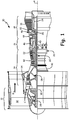
- FIG. 1 schematically illustrates an example gas turbine engine 10 that includes fan section 12, compressor section 14, combustor section 16 and turbine section 18.
- Fan section 12 drives air along bypass flow path B while compressor section 14 draws air in along core flow path C where air is compressed and communicated to combustor section 16.
- combustor section 16 air is mixed with fuel and ignited to generate a high pressure exhaust gas stream that expands through turbine section 18 where energy is extracted and utilized to drive fan section 12 and compressor section 14.
- Example engine 10 generally includes low speed spool 20 and high speed spool 22 mounted for rotation about an engine central longitudinal axis A relative to engine static structure 26 via several bearing systems 28. It should be understood that various bearing systems 28 and various locations may alternatively or additionally be provided.
- Low speed spool 20 generally includes inner shaft 30 that connects fan 32 and low pressure (or first) compressor section 34 to low pressure (or first) turbine section 36.
- Inner shaft 30 drives fan 32 through a speed change device, such as geared architecture 38, to drive fan 32 at a lower speed than the low speed spool 20.
- High speed spool 22 includes outer shaft 40 that interconnects high pressure (or second) compressor section 42 and high pressure (or second) turbine section 44.
- Inner shaft 30 and outer shaft 40 are concentric and rotate via bearing system 28 about engine central longitudinal axis A.
- Combustor 46 is arranged between high pressure compressor 42 and high pressure turbine 44.
- high pressure turbine 44 includes at least two stages to provide a double stage high pressure turbine 44.
- high pressure turbine 44 includes only a single stage.
- a "high pressure" compressor or turbine experiences a higher pressure than a corresponding "low pressure” compressor or turbine.
- Mid turbine frame 48 of engine static structure 26 is arranged generally between high pressure turbine 44 and low pressure turbine 36. Mid frame 48 further supports bearing systems 28 and turbine section 18 as well as directing airflow entering low pressure turbine 36.
- Airflow through core flow path C is compressed by low pressure compressor 34 then by high pressure compressor 42 mixed with fuel and ignited in combustor 46 to produce high speed exhaust gases that are then expanded through high pressure turbine 44 and low pressure turbine 36.
- Mid turbine frame 48 includes vanes 50 which are in the core airflow path and function as an inlet guide vane for low pressure turbine 36. Utilizing vane 50 of mid turbine frame 48 as inlet guide vane for low pressure turbine 36 decreases the length of low pressure turbine 36 without increasing the axial length of mid turbine frame 48. Reducing or eliminating the number of vanes in low pressure turbine 36 shortens the axial length of turbine section 18. Thus the compactness of gas turbine engine 10 is increased and a higher power density may be achieved.
- the example describes a plurality of bleed air outlets and associated duct work as well as heat exchanger components with internal passages connected to high pressure compressor 42 that, when fabricated by electron beam additive manufacturing (EBAM), are faced with issues of removing sintered powder from the passages following fabrication.
- EBAM electron beam additive manufacturing
- EBAM process 80 is shown in FIG. 2 .
- a digital layer by layer model of a metal part is created (step 81).
- the model is loaded into the control system of an EBAM manufacturing system (step 82).
- a single layer of metal powder with a diameter of from about 20 microns to about 100 microns having the desired alloy composition is deposited on a build platform in the EBAM system (step 83).
- a focused electron beam (EB) is then scanned over the entire build platform to partially sinter the layer (step 84).
- the EB is scanned over the sintered powder, typically at a slower rate to fuse portions of the layer that form a solid portion of the final product according to the layer by layer model of the product (step 85).
- the build platform is then indexed down by one powder layer thickness.
- Another layer of powder is added and the sintering and fusing operations are repeated (step 86).
- the step by step process is repeated until the part is complete (step 87).
- the part is then removed from the EBAM manufacturing system and the partially sintered, unfused powder is removed from the part (step 88). If necessary, selected surfaces are mechanically finished to produce a final part (step 89).
- FIG. 3 is a diagram illustrating EBAM system 92 used to form parts having internal passages. Alloy powder is held in powder supply 94 and powder is deposited on build table 96 in vacuum chamber 98. Filament 100, grid cup 102 and anode 104 create electron beam 106, which passes through focus coil 108 and is directed by deflection coil 110 to strike selected areas of the powder layer on build table 96 at position 112. Beam 106 moves based on a predetermined two dimensional pattern from the digital file. Once the pattern is complete for one layer, a next layer of powder and a new two dimensional pattern are subjected to the same treatment until all the patterns have been applied. Build table 96 is designed to be lowered by the thickness of the alloy powder layer after each pass.
- powder may have an average diameter of from about 20 microns to about 100 microns, though other powder sizes may be used.
- the component being built may be made of a nickel base alloy, cobalt base alloy, iron base alloy, titanium base alloy, aluminum base alloy, copper base alloy, or mixtures thereof
- EBAM additive manufacturing there are two forms of metal in a finished part.
- One form is the solid fused alloy product itself.
- the other form is partially sintered alloy powder that is sintered to the degree where it forms a frangible, but solid powder structure that will not flow freely under the influence of gravity. A sufficient number of interparticle bonds must be broken in order for the unfused powder to be removed from the finished part.
- an abrasive grit blast process using matching metal powder is used to remove the partially sintered powder from external surfaces and shallow recesses of an EBAM manufactured part. Removal of partially sintered powder from internal chambers and non-line of sight passages remains a problem in EBAM structures.
- FIGS. 4A and 4B are diagrams illustrating a process by which the above-mentioned difficult-to-remove partially sintered powder can be removed from internal passages and chambers.
- FIG. 4A is a schematic view of a cross-section of metal duct 120 fabricated by EBAM.
- Metal duct 120 comprises solid wall 122 and solid end flanges 124 and 126.
- the interior of duct 120 is filled with partially sintered alloy powder 128 and helical wire cutter 130.
- Helical wire cutter 130 is co-grown in the interior of duct 120 during EBAM manufacturing of duct 120 - that is, the digital layer by layer model of the metal part, including metal duct 120, includes a layer by layer model of helical wire cutter 130 so that the structure of helical wire cutter 130 is formed inside metal duct 120 during the EBAM process.
- the diameter of wire cutter 130 may be from about 0.020 inches (0.51mm) to about 0.25 inches (6.35mm). In a particular embodiment, the diameter of wire cutter 130 may be from about 0.060 inches (1.52 mm) to about 0.125 inches (3.18mm).
- wire cutter 130 may be a helix with a radial shape of a circle, oval, square, or triangle, for example.
- wire cutter 130 is pulled in the direction of arrow A to extract wire cutter 130 from duct 120.
- the end of wire cutter 130 may have a gripping element such as a loop, ball, threads, or another gripping element known in the art.
- wire cutter 130 As wire cutter 130 is extracted from duct 120, the coils of wire cutter 130 straighten. Straightening of wire cutter 130 imparts a localized shearing action on partially sintered powder 128, thereby separating weak interparticle bonds in the powder in the region near end flange 126, which causes the powder to be ejected from duct 120 as schematically indicated by arrows E as shown in FIG. 4B . Removal of the partially sintered powder from the cavity may be assisted by orienting the part to enable gravity, vibration, and air jet or fluid jet.
- partially sintered powder extraction by the present invention may be improved by nesting multiple helical wire cutters inside one another. This may be useful in passages with larger cross-sections. While the invention discloses a method to remove partially sintered powder from a narrow passage, assemblies of wire cutters arranged in large inaccessible inner chambers may also be formed to perform the same function.
- a method of removing partially sintered powder from an internal passage in a metal component formed by electron beam additive manufacturing includes: co-forming a solid wire cutter in the passage during EBAM formation of the metal component; and removing partially sintered powder from the passage by extracting the solid wire cutter from the passage.
- EBAM electron beam additive manufacturing
- the method of preceding paragraph can optionally include, additionally and/or alternatively any, one or more of the following features, configurations and/or additional components:
- the solid wire cutter is a helical coil with a radial shape that conforms to the interior of the passage such that as the wire coil straightens during extraction, the solid wire cutter shears interparticle bonds in the partially sintered powder.
- the end of the solid wire cutter may include a gripping element such as a loop, a ball, or threads.
- the radial shape may be a circle, oval, square, or triangle.
- the cutter may be nested helical coils.
- the cutter may be assemblies of wire cutters arranged in a large inaccessible chamber in the metal component.
- the metal component may be a nickel base alloy, cobalt base alloy, iron base alloy, titanium base alloy, aluminum base alloy, copper base alloy, or mixtures thereof.
- the solid wire diameter may be from about 0.020 inches (0.51 mm) to about 0.25 inches (6.35 mm).
- the solid wire diameter may be from about 0.060 inches (1.52 mm) to about 0.125 inches (3.18 mm).
- a cutter configured to remove partially sintered powder from an internal passage in a metal component formed by electron beam additive manufacturing includes: a solid wire formed inside the passage by the EBAM process, where the solid wire may be a helical coil with a radial shape that conforms to the interior of the passage and may be configured and arranged for the solid wire to shear interparticle bonds in the partially sintered powder in response to the coil straightening during extraction from the passage causing the partially sintered powder to be removed from the passage.
- EBAM electron beam additive manufacturing
- the cutter of the preceding paragraph can optionally include, additionally and/or alternatively any, one or more of the following features, configurations, and/or additional components:
- the end of the solid wire may include a gripping element such as a loop, a ball, or threads.
- the radial shape may be a circle, oval, square, or triangle.
- the metal component may be a nickel base alloy, cobalt base alloy, iron base alloy, titanium base alloy, aluminum base alloy, copper base alloy, or mixtures thereof.
- the solid wire may have a diameter of from about 0.020 inches (0.51 mm) to about 0.25 inches (6.35 mm).
- the solid wire may have a diameter of from about 0.060 inches (1.52 mm) to about 0.125 inches (3.18 mm).
- the cutter may be nested helical coils.
- the metal component may be a gas turbine engine component.
- the gas turbine engine component may be a heat exchanger, bleed air system, or lubrication system.
Landscapes
- Engineering & Computer Science (AREA)
- Mechanical Engineering (AREA)
- Manufacturing & Machinery (AREA)
- Chemical & Material Sciences (AREA)
- Materials Engineering (AREA)
- Life Sciences & Earth Sciences (AREA)
- Forests & Forestry (AREA)
- Physics & Mathematics (AREA)
- Plasma & Fusion (AREA)
- Powder Metallurgy (AREA)
Abstract
Description
- This invention relates to fluid passageways in gas turbine engines. In particular the invention relates to fluid passageways such as lightweight metal ducts formed by electron beam additive manufacturing (EBAM).
- Gas turbine engines typically include a compressor section to pressurize airflow, a combustor section to burn a hydrocarbon fuel in the presence of the pressurized air, and a turbine section to extract energy from the resultant combusting gasses.
- In the gas turbine industry, methods for fabricating components with internal passageways such as blades and vanes in the turbine section and fluid ducts in other sections such as bleed-air systems and lubrication systems using additive manufacturing invite significant attention. Since a component is produced in a continuous process in an additive manufacturing operation, features associated with conventional manufacturing processes such as machining, forging, welding, casting, etc. can be eliminated leading to savings in weight, cost, material and time.
- An inherent feature of metallic components with internal passageways fabricated by powder based additive manufacturing is that removal of partially sintered powder in completed fused passageways following fabrication may be an issue.
- A method of removing partially sintered powder from an internal passage in a metal component formed by electron beam additive manufacturing (EBAM) includes co-forming a solid wire cutter in the passage during the EBAM forming process and removing partially sintered powder from the cavity by extracting the cutter from the cavity.
- In an embodiment a cutter for removing partially sintered powder from an internal passage in a metal component formed by electron beam additive manufacturing (EBAM) consists of a solid wire in the form of a helical coil with a radial shape that conforms to, but is not attached to, the interior of the passage such that as the coil straightens out during extraction, the wire shears interparticle bonds in the sintered powder allowing the powder to be removed from the passage along with the cutter.
-
-
FIG. 1 is a schematic view of an example gas turbine engine. -
FIG. 2 is a flow diagram of an electron beam additive manufacturing process. -
FIG. 3 is a schematic view of a representative electron beam additive manufacturing process. -
FIG. 4A and 4B are schematic views before and during powder removal of the invention. -
FIG. 1 schematically illustrates an examplegas turbine engine 10 that includesfan section 12,compressor section 14,combustor section 16 andturbine section 18.Fan section 12 drives air along bypass flow path B whilecompressor section 14 draws air in along core flow path C where air is compressed and communicated tocombustor section 16. Incombustor section 16, air is mixed with fuel and ignited to generate a high pressure exhaust gas stream that expands throughturbine section 18 where energy is extracted and utilized to drivefan section 12 andcompressor section 14. -
Example engine 10 generally includeslow speed spool 20 andhigh speed spool 22 mounted for rotation about an engine central longitudinal axis A relative to enginestatic structure 26 viaseveral bearing systems 28. It should be understood thatvarious bearing systems 28 and various locations may alternatively or additionally be provided. -
Low speed spool 20 generally includesinner shaft 30 that connectsfan 32 and low pressure (or first)compressor section 34 to low pressure (or first)turbine section 36.Inner shaft 30 drivesfan 32 through a speed change device, such as gearedarchitecture 38, to drivefan 32 at a lower speed than thelow speed spool 20.High speed spool 22 includesouter shaft 40 that interconnects high pressure (or second)compressor section 42 and high pressure (or second)turbine section 44.Inner shaft 30 andouter shaft 40 are concentric and rotate viabearing system 28 about engine central longitudinal axis A. - Combustor 46 is arranged between
high pressure compressor 42 andhigh pressure turbine 44. In one example,high pressure turbine 44 includes at least two stages to provide a double stagehigh pressure turbine 44. In another examplehigh pressure turbine 44 includes only a single stage. As used herein, a "high pressure" compressor or turbine experiences a higher pressure than a corresponding "low pressure" compressor or turbine. -
Mid turbine frame 48 of enginestatic structure 26 is arranged generally betweenhigh pressure turbine 44 andlow pressure turbine 36.Mid frame 48 further supports bearingsystems 28 andturbine section 18 as well as directing airflow enteringlow pressure turbine 36. - Airflow through core flow path C is compressed by
low pressure compressor 34 then byhigh pressure compressor 42 mixed with fuel and ignited incombustor 46 to produce high speed exhaust gases that are then expanded throughhigh pressure turbine 44 andlow pressure turbine 36.Mid turbine frame 48 includesvanes 50 which are in the core airflow path and function as an inlet guide vane forlow pressure turbine 36. Utilizingvane 50 ofmid turbine frame 48 as inlet guide vane forlow pressure turbine 36 decreases the length oflow pressure turbine 36 without increasing the axial length ofmid turbine frame 48. Reducing or eliminating the number of vanes inlow pressure turbine 36 shortens the axial length ofturbine section 18. Thus the compactness ofgas turbine engine 10 is increased and a higher power density may be achieved. - The example bleed air system discussed here is described in commonly owned
U.S. Patent Application Publication No. 2014/0165588 to Snape et al. , which is incorporated herein by reference in its entirety. - The example describes a plurality of bleed air outlets and associated duct work as well as heat exchanger components with internal passages connected to
high pressure compressor 42 that, when fabricated by electron beam additive manufacturing (EBAM), are faced with issues of removing sintered powder from the passages following fabrication. A method for removing the sintered powder from these passages is described below. - The electron beam additive manufacturing (EBAM) process for forming components having internal passages is discussed in commonly owned
U.S. Patent Application Publication No. 2014/0169981 to Bales et al. , which is incorporated herein by reference in its entirety. EBAMprocess 80 is shown inFIG. 2 . In the first step, a digital layer by layer model of a metal part is created (step 81). In the next step, the model is loaded into the control system of an EBAM manufacturing system (step 82). A single layer of metal powder with a diameter of from about 20 microns to about 100 microns having the desired alloy composition is deposited on a build platform in the EBAM system (step 83). A focused electron beam (EB) is then scanned over the entire build platform to partially sinter the layer (step 84). In the next step, the EB is scanned over the sintered powder, typically at a slower rate to fuse portions of the layer that form a solid portion of the final product according to the layer by layer model of the product (step 85). In the build process, the build platform is then indexed down by one powder layer thickness. Another layer of powder is added and the sintering and fusing operations are repeated (step 86). The step by step process is repeated until the part is complete (step 87). The part is then removed from the EBAM manufacturing system and the partially sintered, unfused powder is removed from the part (step 88). If necessary, selected surfaces are mechanically finished to produce a final part (step 89). -
FIG. 3 is a diagram illustratingEBAM system 92 used to form parts having internal passages. Alloy powder is held inpowder supply 94 and powder is deposited on build table 96 invacuum chamber 98.Filament 100,grid cup 102 andanode 104 createelectron beam 106, which passes throughfocus coil 108 and is directed bydeflection coil 110 to strike selected areas of the powder layer on build table 96 atposition 112. Beam 106 moves based on a predetermined two dimensional pattern from the digital file. Once the pattern is complete for one layer, a next layer of powder and a new two dimensional pattern are subjected to the same treatment until all the patterns have been applied. Build table 96 is designed to be lowered by the thickness of the alloy powder layer after each pass. As noted above, powder may have an average diameter of from about 20 microns to about 100 microns, though other powder sizes may be used. The component being built may be made of a nickel base alloy, cobalt base alloy, iron base alloy, titanium base alloy, aluminum base alloy, copper base alloy, or mixtures thereof - As noted above, with EBAM additive manufacturing, there are two forms of metal in a finished part. One form is the solid fused alloy product itself. The other form is partially sintered alloy powder that is sintered to the degree where it forms a frangible, but solid powder structure that will not flow freely under the influence of gravity. A sufficient number of interparticle bonds must be broken in order for the unfused powder to be removed from the finished part. Typically, an abrasive grit blast process using matching metal powder is used to remove the partially sintered powder from external surfaces and shallow recesses of an EBAM manufactured part. Removal of partially sintered powder from internal chambers and non-line of sight passages remains a problem in EBAM structures.
-
FIGS. 4A and 4B are diagrams illustrating a process by which the above-mentioned difficult-to-remove partially sintered powder can be removed from internal passages and chambers.FIG. 4A is a schematic view of a cross-section ofmetal duct 120 fabricated by EBAM.Metal duct 120 comprisessolid wall 122 andsolid end flanges duct 120 is filled with partially sinteredalloy powder 128 andhelical wire cutter 130.Helical wire cutter 130 is co-grown in the interior ofduct 120 during EBAM manufacturing of duct 120 - that is, the digital layer by layer model of the metal part, includingmetal duct 120, includes a layer by layer model ofhelical wire cutter 130 so that the structure ofhelical wire cutter 130 is formed insidemetal duct 120 during the EBAM process. The diameter ofwire cutter 130 may be from about 0.020 inches (0.51mm) to about 0.25 inches (6.35mm). In a particular embodiment, the diameter ofwire cutter 130 may be from about 0.060 inches (1.52 mm) to about 0.125 inches (3.18mm). In various embodiments,wire cutter 130 may be a helix with a radial shape of a circle, oval, square, or triangle, for example. To effect removal of partially sinteredpowder 128 fromduct 120,wire cutter 130 is pulled in the direction of arrow A to extractwire cutter 130 fromduct 120. In order to aid extraction, the end ofwire cutter 130 may have a gripping element such as a loop, ball, threads, or another gripping element known in the art. - As
wire cutter 130 is extracted fromduct 120, the coils ofwire cutter 130 straighten. Straightening ofwire cutter 130 imparts a localized shearing action on partially sinteredpowder 128, thereby separating weak interparticle bonds in the powder in the region nearend flange 126, which causes the powder to be ejected fromduct 120 as schematically indicated by arrows E as shown inFIG. 4B . Removal of the partially sintered powder from the cavity may be assisted by orienting the part to enable gravity, vibration, and air jet or fluid jet. - In an embodiment, partially sintered powder extraction by the present invention may be improved by nesting multiple helical wire cutters inside one another. This may be useful in passages with larger cross-sections. While the invention discloses a method to remove partially sintered powder from a narrow passage, assemblies of wire cutters arranged in large inaccessible inner chambers may also be formed to perform the same function.
- The following are non-exclusive descriptions of possible embodiments of the present invention.
- A method of removing partially sintered powder from an internal passage in a metal component formed by electron beam additive manufacturing (EBAM) includes: co-forming a solid wire cutter in the passage during EBAM formation of the metal component; and removing partially sintered powder from the passage by extracting the solid wire cutter from the passage.
- The method of preceding paragraph can optionally include, additionally and/or alternatively any, one or more of the following features, configurations and/or additional components:
- Extracting the solid wire cutter from the passage includes gripping an end of the solid wire cutter and pulling it out of the passage.
- The solid wire cutter is a helical coil with a radial shape that conforms to the interior of the passage such that as the wire coil straightens during extraction, the solid wire cutter shears interparticle bonds in the partially sintered powder.
- The end of the solid wire cutter may include a gripping element such as a loop, a ball, or threads.
- The radial shape may be a circle, oval, square, or triangle.
- The cutter may be nested helical coils.
- The cutter may be assemblies of wire cutters arranged in a large inaccessible chamber in the metal component.
- The metal component may be a nickel base alloy, cobalt base alloy, iron base alloy, titanium base alloy, aluminum base alloy, copper base alloy, or mixtures thereof.
- The solid wire diameter may be from about 0.020 inches (0.51 mm) to about 0.25 inches (6.35 mm).
- The solid wire diameter may be from about 0.060 inches (1.52 mm) to about 0.125 inches (3.18 mm).
- A cutter configured to remove partially sintered powder from an internal passage in a metal component formed by electron beam additive manufacturing (EBAM) includes: a solid wire formed inside the passage by the EBAM process, where the solid wire may be a helical coil with a radial shape that conforms to the interior of the passage and may be configured and arranged for the solid wire to shear interparticle bonds in the partially sintered powder in response to the coil straightening during extraction from the passage causing the partially sintered powder to be removed from the passage.
- The cutter of the preceding paragraph can optionally include, additionally and/or alternatively any, one or more of the following features, configurations, and/or additional components:
- The cutter may be configured such that extraction from the passage is performed by gripping an end of the solid wire and pulling the solid wire out of the passage.
- The end of the solid wire may include a gripping element such as a loop, a ball, or threads.
- The radial shape may be a circle, oval, square, or triangle.
- The metal component may be a nickel base alloy, cobalt base alloy, iron base alloy, titanium base alloy, aluminum base alloy, copper base alloy, or mixtures thereof.
- The solid wire may have a diameter of from about 0.020 inches (0.51 mm) to about 0.25 inches (6.35 mm).
- The solid wire may have a diameter of from about 0.060 inches (1.52 mm) to about 0.125 inches (3.18 mm).
- The cutter may be nested helical coils.
- The metal component may be a gas turbine engine component.
- The gas turbine engine component may be a heat exchanger, bleed air system, or lubrication system.
- While the invention has been described with reference to an exemplary embodiment(s), it will be understood by those skilled in the art that various changes may be made and equivalents may be substituted for elements thereof without departing from the scope of the invention. In addition, many modifications may be made to adapt a particular situation or material to the teachings of the invention without departing from the essential scope thereof. Therefore, it is intended that the invention not be limited to the particular embodiment(s) disclosed, but that the invention will include all embodiments falling within the scope of the appended claims.
Claims (15)
- A method of removing partially sintered powder (128) from an internal passage in a metal component (120) formed by electron beam additive manufacturing (EBAM) comprising:co-forming a solid wire cutter (130) in the passage during EBAM formation of the metal component (120); andremoving partially sintered powder (128) from the passage by extracting the solid wire cutter (130) from the passage.
- The method of claim 1, wherein extracting the solid wire cutter (130) from the passage comprises gripping an end of the solid wire cutter (130) and pulling it out of the passage.
- The method of claim 2, wherein an end of the solid wire cutter (130) includes a gripping element comprising a loop, a ball, or threads.
- The method of claim 1, 2 or 3, wherein the solid wire cutter (130) is a helical coil with a radial shape that conforms to an interior of the passage such that as the wire coil straightens during extraction, the solid wire cutter (130) shears interparticle bonds in the partially sintered powder (128).
- A cutter (130) configured to remove partially sintered powder (128) from an internal passage in a metal component (120) formed by electron beam additive manufacturing (EBAM), comprising:a solid wire (130) formed inside the passage by the EBAM process, the solid wire (130) being a helical coil with a radial shape that conforms to an interior of the passage, configured and arranged so the solid wire (130) shears interparticle bonds in the partially sintered powder (128) in response to straightening of the coil during extraction from the passage, causing the partially sintered powder (128) to be removed from the passage.
- The cutter of claim 5, wherein the cutter (130) is configured such that extraction from the passage is performed by gripping an end of the solid wire (130) and pulling the solid wire out of the passage.
- The cutter of claim 6, wherein the end of the solid wire (130) includes a gripping element comprising a loop, a ball, or threads.
- The method or cutter of any of claims 4 to 7, wherein the radial shape comprises a circle, oval, square, or triangle.
- The method or cutter of any of claims 4 to 8, wherein the cutter (130) comprises nested helical coils.
- The method or cutter of any preceding claim wherein the metal component (120) is made of a nickel base alloy, cobalt base alloy, iron base alloy, titanium base alloy, aluminum base alloy, copper base alloy, or mixtures thereof.
- The method or cutter of any preceding claim, wherein the solid wire (130) has a diameter of from about 0.020 inches (0.51 mm) to about 0.25 inches (6.35 mm).
- The method or cutter of any preceding claim, wherein the solid wire (130) has a diameter of from about 0.060 inches (1.52 mm) to about 0.125 inches (3.18 mm).
- The method or cutter of any preceding claim, wherein the cutter (130) comprises assemblies of wire cutters arranged in a large inaccessible chamber in the metal component (120).
- The method or cutter of any preceding claim, wherein the metal component (120) comprises a gas turbine engine component.
- The method or cutter of claim 14, wherein the gas turbine engine component is one of a heat exchanger, bleed air system, or lubrication system.
Applications Claiming Priority (1)
| Application Number | Priority Date | Filing Date | Title |
|---|---|---|---|
| US14/994,351 US20170197284A1 (en) | 2016-01-13 | 2016-01-13 | Method for removing partially sintered powder from internal passages in electron beam additive manufactured parts |
Publications (2)
| Publication Number | Publication Date |
|---|---|
| EP3192599A1 true EP3192599A1 (en) | 2017-07-19 |
| EP3192599B1 EP3192599B1 (en) | 2019-03-13 |
Family
ID=58046445
Family Applications (1)
| Application Number | Title | Priority Date | Filing Date |
|---|---|---|---|
| EP17151509.1A Active EP3192599B1 (en) | 2016-01-13 | 2017-01-13 | Method for removing partially sintered powder from internal passages of electron beam additive manufactured parts |
Country Status (2)
| Country | Link |
|---|---|
| US (1) | US20170197284A1 (en) |
| EP (1) | EP3192599B1 (en) |
Cited By (5)
| Publication number | Priority date | Publication date | Assignee | Title |
|---|---|---|---|---|
| EP3219417A1 (en) * | 2016-03-18 | 2017-09-20 | United Technologies Corporation | Sacrificial core for conglomerated powder removal |
| EP3219418A1 (en) * | 2016-03-18 | 2017-09-20 | United Technologies Corporation | Sacrificial core for conglomerated powder removal |
| EP3478433A1 (en) * | 2016-07-01 | 2019-05-08 | General Electric Company | Methods and multi-purpose powder removal features for additive manufacturing |
| WO2019237016A1 (en) * | 2018-06-08 | 2019-12-12 | General Electric Company | Powder removal floating structures |
| EP3747600A1 (en) * | 2019-06-06 | 2020-12-09 | Raytheon Technologies Corporation | Apparatus and methods for improvement of surface geometries of internal channels of additively manufactured components |
Families Citing this family (9)
| Publication number | Priority date | Publication date | Assignee | Title |
|---|---|---|---|---|
| GB201502086D0 (en) * | 2015-02-09 | 2015-03-25 | Rolls Royce Plc | Methods of manufacturing and cleaning |
| GB2569349A (en) * | 2017-12-14 | 2019-06-19 | Airbus Operations Ltd | Post-processing of additive layer manufactured part |
| US20190201982A1 (en) | 2018-01-03 | 2019-07-04 | General Electric Company | Systems and methods for removing build material from additively manufactured parts |
| US11148248B2 (en) | 2018-04-19 | 2021-10-19 | Raytheon Technologies Corporation | Smoothing round internal passages of additively manufactured parts using metallic spheres |
| US11364587B2 (en) | 2018-04-19 | 2022-06-21 | Raytheon Technologies Corporation | Flow directors and shields for abrasive flow machining of internal passages |
| US20200189494A1 (en) * | 2018-12-13 | 2020-06-18 | Safran Landing Systems Canada Inc. | Landing gear structure with harness |
| US11471947B2 (en) | 2019-06-06 | 2022-10-18 | Raytheon Technologies Corporation | Apparatus and methods for improvement of surface geometries of internal channels of additively manufactured components |
| US12485617B2 (en) * | 2023-09-26 | 2025-12-02 | GM Global Technology Operations LLC | Systems and methods for creating a powder removal tool via additive manufacturing |
| CN119525677A (en) * | 2024-11-27 | 2025-02-28 | 哈尔滨工业大学 | A method for electron beam fuse additive manufacturing of titanium steel heterogeneous metal materials |
Citations (6)
| Publication number | Priority date | Publication date | Assignee | Title |
|---|---|---|---|---|
| US20060118532A1 (en) * | 2004-12-07 | 2006-06-08 | 3D Systems, Inc. | Controlled cooling methods and apparatus for laser sintering part-cake |
| JP2013194263A (en) * | 2012-03-16 | 2013-09-30 | Panasonic Corp | Method of manufacturing three-dimensionally shaped object |
| US20140169981A1 (en) | 2012-12-14 | 2014-06-19 | United Technologies Corporation | Uber-cooled turbine section component made by additive manufacturing |
| US20140165588A1 (en) | 2012-12-14 | 2014-06-19 | United Technologies Corporation | Turbo compressor for bleed air |
| GB2517490A (en) * | 2013-08-23 | 2015-02-25 | Univ Montfort | Additive manufacturing methods |
| EP3069805A2 (en) * | 2015-03-17 | 2016-09-21 | Hamilton Sundstrand Corporation | Powered removal for element formed by electron beam melting |
Family Cites Families (2)
| Publication number | Priority date | Publication date | Assignee | Title |
|---|---|---|---|---|
| US6811744B2 (en) * | 1999-07-07 | 2004-11-02 | Optomec Design Company | Forming structures from CAD solid models |
| DE102010019447A1 (en) * | 2010-05-05 | 2011-11-10 | Eos Gmbh Electro Optical Systems | A method for generatively producing a three-dimensional object with reamers and method for creating a corresponding dataset |
-
2016
- 2016-01-13 US US14/994,351 patent/US20170197284A1/en not_active Abandoned
-
2017
- 2017-01-13 EP EP17151509.1A patent/EP3192599B1/en active Active
Patent Citations (6)
| Publication number | Priority date | Publication date | Assignee | Title |
|---|---|---|---|---|
| US20060118532A1 (en) * | 2004-12-07 | 2006-06-08 | 3D Systems, Inc. | Controlled cooling methods and apparatus for laser sintering part-cake |
| JP2013194263A (en) * | 2012-03-16 | 2013-09-30 | Panasonic Corp | Method of manufacturing three-dimensionally shaped object |
| US20140169981A1 (en) | 2012-12-14 | 2014-06-19 | United Technologies Corporation | Uber-cooled turbine section component made by additive manufacturing |
| US20140165588A1 (en) | 2012-12-14 | 2014-06-19 | United Technologies Corporation | Turbo compressor for bleed air |
| GB2517490A (en) * | 2013-08-23 | 2015-02-25 | Univ Montfort | Additive manufacturing methods |
| EP3069805A2 (en) * | 2015-03-17 | 2016-09-21 | Hamilton Sundstrand Corporation | Powered removal for element formed by electron beam melting |
Cited By (9)
| Publication number | Priority date | Publication date | Assignee | Title |
|---|---|---|---|---|
| EP3219417A1 (en) * | 2016-03-18 | 2017-09-20 | United Technologies Corporation | Sacrificial core for conglomerated powder removal |
| EP3219418A1 (en) * | 2016-03-18 | 2017-09-20 | United Technologies Corporation | Sacrificial core for conglomerated powder removal |
| EP3478433A1 (en) * | 2016-07-01 | 2019-05-08 | General Electric Company | Methods and multi-purpose powder removal features for additive manufacturing |
| EP3478433B1 (en) * | 2016-07-01 | 2026-01-14 | General Electric Company | Methods and multi-purpose powder removal features for additive manufacturing |
| WO2019237016A1 (en) * | 2018-06-08 | 2019-12-12 | General Electric Company | Powder removal floating structures |
| US11344949B2 (en) | 2018-06-08 | 2022-05-31 | General Electric Company | Powder removal floating structures |
| US12103227B2 (en) | 2018-06-08 | 2024-10-01 | General Electric Company | Powder removal floating structures |
| EP3747600A1 (en) * | 2019-06-06 | 2020-12-09 | Raytheon Technologies Corporation | Apparatus and methods for improvement of surface geometries of internal channels of additively manufactured components |
| US11376661B2 (en) | 2019-06-06 | 2022-07-05 | Raytheon Technologies Corporation | Apparatus and methods for improvement of surface geometries of internal channels of additively manufactured components |
Also Published As
| Publication number | Publication date |
|---|---|
| EP3192599B1 (en) | 2019-03-13 |
| US20170197284A1 (en) | 2017-07-13 |
Similar Documents
| Publication | Publication Date | Title |
|---|---|---|
| EP3192599B1 (en) | Method for removing partially sintered powder from internal passages of electron beam additive manufactured parts | |
| US10865647B2 (en) | Turbo-machine impeller manufacturing | |
| JP4732718B2 (en) | Process for manufacturing a forged titanium compressor impeller | |
| EP3052784B1 (en) | Additive manufactured fuel nozzle core for a gas turbine engine | |
| US6190133B1 (en) | High stiffness airoil and method of manufacture | |
| EP3034228A2 (en) | A method of producing an integrally bladed rotor for a turbomachine | |
| EP2047945A1 (en) | Method of manufacturing a turbine rotor and corresponding turbine rotor | |
| JP2017522488A (en) | Manufacturing turbomachinery impellers by assembling multiple tubular parts | |
| EP3663525B1 (en) | Axial flow cooling scheme with castable structural rib for gas turbine engine | |
| US11105212B2 (en) | Gas turbine engines including tangential on-board injectors and methods for manufacturing the same | |
| JP2017109245A (en) | Method and assembly for forming a component having internal passages using a lattice structure | |
| US20130156558A1 (en) | Annular gas turbine engine case and method of manufacturing | |
| US10408083B2 (en) | Hollow metal objects and methods for making same | |
| CH707668A2 (en) | Gas turbine system. | |
| JP5203556B2 (en) | Method for producing components of hollow blades by rolling | |
| CN114607471A (en) | Airfoil with adjustable cooling configuration | |
| EP3550107B1 (en) | Method of producing a gas turbine engine component | |
| US11806939B2 (en) | Kinetic disassembly of support structure system for additively manufactured rotating components | |
| EP2841700B1 (en) | Airfoil support method and apparatus | |
| CA2602994C (en) | Annular gas turbine engine case and method of manufacturing | |
| EP1653054B1 (en) | Method for manufacturing aircraft engine cases with bosses | |
| EP3926144A1 (en) | Monolithic diffuser and deswirl flow structure for gas turbine engine | |
| EP2230037A1 (en) | Method of manufacture of a dual microstructure impeller | |
| US12442309B2 (en) | Nozzle assembly for turbine engine | |
| EP3009212B1 (en) | Manufacturing method of a leading edge of an aerofoil component |
Legal Events
| Date | Code | Title | Description |
|---|---|---|---|
| PUAI | Public reference made under article 153(3) epc to a published international application that has entered the european phase |
Free format text: ORIGINAL CODE: 0009012 |
|
| STAA | Information on the status of an ep patent application or granted ep patent |
Free format text: STATUS: THE APPLICATION HAS BEEN PUBLISHED |
|
| AK | Designated contracting states |
Kind code of ref document: A1 Designated state(s): AL AT BE BG CH CY CZ DE DK EE ES FI FR GB GR HR HU IE IS IT LI LT LU LV MC MK MT NL NO PL PT RO RS SE SI SK SM TR |
|
| AX | Request for extension of the european patent |
Extension state: BA ME |
|
| STAA | Information on the status of an ep patent application or granted ep patent |
Free format text: STATUS: REQUEST FOR EXAMINATION WAS MADE |
|
| 17P | Request for examination filed |
Effective date: 20180119 |
|
| RBV | Designated contracting states (corrected) |
Designated state(s): AL AT BE BG CH CY CZ DE DK EE ES FI FR GB GR HR HU IE IS IT LI LT LU LV MC MK MT NL NO PL PT RO RS SE SI SK SM TR |
|
| RIC1 | Information provided on ipc code assigned before grant |
Ipc: B22F 5/00 20060101ALI20180725BHEP Ipc: B26D 1/547 20060101ALI20180725BHEP Ipc: B22F 5/10 20060101ALI20180725BHEP Ipc: B22F 3/24 20060101ALN20180725BHEP Ipc: B22F 3/105 20060101AFI20180725BHEP Ipc: B23D 61/18 20060101ALI20180725BHEP Ipc: B26D 1/553 20060101ALI20180725BHEP |
|
| RIC1 | Information provided on ipc code assigned before grant |
Ipc: B26D 1/553 20060101ALI20180806BHEP Ipc: B22F 5/00 20060101ALI20180806BHEP Ipc: B23D 61/18 20060101ALI20180806BHEP Ipc: B22F 3/24 20060101ALN20180806BHEP Ipc: B22F 3/105 20060101AFI20180806BHEP Ipc: B22F 5/10 20060101ALI20180806BHEP Ipc: B26D 1/547 20060101ALI20180806BHEP |
|
| GRAP | Despatch of communication of intention to grant a patent |
Free format text: ORIGINAL CODE: EPIDOSNIGR1 |
|
| STAA | Information on the status of an ep patent application or granted ep patent |
Free format text: STATUS: GRANT OF PATENT IS INTENDED |
|
| INTG | Intention to grant announced |
Effective date: 20180918 |
|
| GRAS | Grant fee paid |
Free format text: ORIGINAL CODE: EPIDOSNIGR3 |
|
| GRAA | (expected) grant |
Free format text: ORIGINAL CODE: 0009210 |
|
| STAA | Information on the status of an ep patent application or granted ep patent |
Free format text: STATUS: THE PATENT HAS BEEN GRANTED |
|
| AK | Designated contracting states |
Kind code of ref document: B1 Designated state(s): AL AT BE BG CH CY CZ DE DK EE ES FI FR GB GR HR HU IE IS IT LI LT LU LV MC MK MT NL NO PL PT RO RS SE SI SK SM TR |
|
| REG | Reference to a national code |
Ref country code: GB Ref legal event code: FG4D |
|
| REG | Reference to a national code |
Ref country code: CH Ref legal event code: EP Ref country code: AT Ref legal event code: REF Ref document number: 1107022 Country of ref document: AT Kind code of ref document: T Effective date: 20190315 |
|
| REG | Reference to a national code |
Ref country code: IE Ref legal event code: FG4D |
|
| REG | Reference to a national code |
Ref country code: DE Ref legal event code: R096 Ref document number: 602017002575 Country of ref document: DE |
|
| REG | Reference to a national code |
Ref country code: NL Ref legal event code: MP Effective date: 20190313 |
|
| REG | Reference to a national code |
Ref country code: LT Ref legal event code: MG4D |
|
| PG25 | Lapsed in a contracting state [announced via postgrant information from national office to epo] |
Ref country code: FI Free format text: LAPSE BECAUSE OF FAILURE TO SUBMIT A TRANSLATION OF THE DESCRIPTION OR TO PAY THE FEE WITHIN THE PRESCRIBED TIME-LIMIT Effective date: 20190313 Ref country code: SE Free format text: LAPSE BECAUSE OF FAILURE TO SUBMIT A TRANSLATION OF THE DESCRIPTION OR TO PAY THE FEE WITHIN THE PRESCRIBED TIME-LIMIT Effective date: 20190313 Ref country code: NO Free format text: LAPSE BECAUSE OF FAILURE TO SUBMIT A TRANSLATION OF THE DESCRIPTION OR TO PAY THE FEE WITHIN THE PRESCRIBED TIME-LIMIT Effective date: 20190613 Ref country code: LT Free format text: LAPSE BECAUSE OF FAILURE TO SUBMIT A TRANSLATION OF THE DESCRIPTION OR TO PAY THE FEE WITHIN THE PRESCRIBED TIME-LIMIT Effective date: 20190313 |
|
| PG25 | Lapsed in a contracting state [announced via postgrant information from national office to epo] |
Ref country code: GR Free format text: LAPSE BECAUSE OF FAILURE TO SUBMIT A TRANSLATION OF THE DESCRIPTION OR TO PAY THE FEE WITHIN THE PRESCRIBED TIME-LIMIT Effective date: 20190614 Ref country code: BG Free format text: LAPSE BECAUSE OF FAILURE TO SUBMIT A TRANSLATION OF THE DESCRIPTION OR TO PAY THE FEE WITHIN THE PRESCRIBED TIME-LIMIT Effective date: 20190613 Ref country code: HR Free format text: LAPSE BECAUSE OF FAILURE TO SUBMIT A TRANSLATION OF THE DESCRIPTION OR TO PAY THE FEE WITHIN THE PRESCRIBED TIME-LIMIT Effective date: 20190313 Ref country code: RS Free format text: LAPSE BECAUSE OF FAILURE TO SUBMIT A TRANSLATION OF THE DESCRIPTION OR TO PAY THE FEE WITHIN THE PRESCRIBED TIME-LIMIT Effective date: 20190313 Ref country code: NL Free format text: LAPSE BECAUSE OF FAILURE TO SUBMIT A TRANSLATION OF THE DESCRIPTION OR TO PAY THE FEE WITHIN THE PRESCRIBED TIME-LIMIT Effective date: 20190313 Ref country code: LV Free format text: LAPSE BECAUSE OF FAILURE TO SUBMIT A TRANSLATION OF THE DESCRIPTION OR TO PAY THE FEE WITHIN THE PRESCRIBED TIME-LIMIT Effective date: 20190313 |
|
| REG | Reference to a national code |
Ref country code: AT Ref legal event code: MK05 Ref document number: 1107022 Country of ref document: AT Kind code of ref document: T Effective date: 20190313 |
|
| PG25 | Lapsed in a contracting state [announced via postgrant information from national office to epo] |
Ref country code: RO Free format text: LAPSE BECAUSE OF FAILURE TO SUBMIT A TRANSLATION OF THE DESCRIPTION OR TO PAY THE FEE WITHIN THE PRESCRIBED TIME-LIMIT Effective date: 20190313 Ref country code: SK Free format text: LAPSE BECAUSE OF FAILURE TO SUBMIT A TRANSLATION OF THE DESCRIPTION OR TO PAY THE FEE WITHIN THE PRESCRIBED TIME-LIMIT Effective date: 20190313 Ref country code: EE Free format text: LAPSE BECAUSE OF FAILURE TO SUBMIT A TRANSLATION OF THE DESCRIPTION OR TO PAY THE FEE WITHIN THE PRESCRIBED TIME-LIMIT Effective date: 20190313 Ref country code: IT Free format text: LAPSE BECAUSE OF FAILURE TO SUBMIT A TRANSLATION OF THE DESCRIPTION OR TO PAY THE FEE WITHIN THE PRESCRIBED TIME-LIMIT Effective date: 20190313 Ref country code: ES Free format text: LAPSE BECAUSE OF FAILURE TO SUBMIT A TRANSLATION OF THE DESCRIPTION OR TO PAY THE FEE WITHIN THE PRESCRIBED TIME-LIMIT Effective date: 20190313 Ref country code: AL Free format text: LAPSE BECAUSE OF FAILURE TO SUBMIT A TRANSLATION OF THE DESCRIPTION OR TO PAY THE FEE WITHIN THE PRESCRIBED TIME-LIMIT Effective date: 20190313 Ref country code: PT Free format text: LAPSE BECAUSE OF FAILURE TO SUBMIT A TRANSLATION OF THE DESCRIPTION OR TO PAY THE FEE WITHIN THE PRESCRIBED TIME-LIMIT Effective date: 20190713 Ref country code: CZ Free format text: LAPSE BECAUSE OF FAILURE TO SUBMIT A TRANSLATION OF THE DESCRIPTION OR TO PAY THE FEE WITHIN THE PRESCRIBED TIME-LIMIT Effective date: 20190313 |
|
| PG25 | Lapsed in a contracting state [announced via postgrant information from national office to epo] |
Ref country code: PL Free format text: LAPSE BECAUSE OF FAILURE TO SUBMIT A TRANSLATION OF THE DESCRIPTION OR TO PAY THE FEE WITHIN THE PRESCRIBED TIME-LIMIT Effective date: 20190313 Ref country code: SM Free format text: LAPSE BECAUSE OF FAILURE TO SUBMIT A TRANSLATION OF THE DESCRIPTION OR TO PAY THE FEE WITHIN THE PRESCRIBED TIME-LIMIT Effective date: 20190313 |
|
| REG | Reference to a national code |
Ref country code: DE Ref legal event code: R097 Ref document number: 602017002575 Country of ref document: DE |
|
| PG25 | Lapsed in a contracting state [announced via postgrant information from national office to epo] |
Ref country code: AT Free format text: LAPSE BECAUSE OF FAILURE TO SUBMIT A TRANSLATION OF THE DESCRIPTION OR TO PAY THE FEE WITHIN THE PRESCRIBED TIME-LIMIT Effective date: 20190313 Ref country code: IS Free format text: LAPSE BECAUSE OF FAILURE TO SUBMIT A TRANSLATION OF THE DESCRIPTION OR TO PAY THE FEE WITHIN THE PRESCRIBED TIME-LIMIT Effective date: 20190713 |
|
| PLBE | No opposition filed within time limit |
Free format text: ORIGINAL CODE: 0009261 |
|
| STAA | Information on the status of an ep patent application or granted ep patent |
Free format text: STATUS: NO OPPOSITION FILED WITHIN TIME LIMIT |
|
| PG25 | Lapsed in a contracting state [announced via postgrant information from national office to epo] |
Ref country code: DK Free format text: LAPSE BECAUSE OF FAILURE TO SUBMIT A TRANSLATION OF THE DESCRIPTION OR TO PAY THE FEE WITHIN THE PRESCRIBED TIME-LIMIT Effective date: 20190313 |
|
| 26N | No opposition filed |
Effective date: 20191216 |
|
| PG25 | Lapsed in a contracting state [announced via postgrant information from national office to epo] |
Ref country code: SI Free format text: LAPSE BECAUSE OF FAILURE TO SUBMIT A TRANSLATION OF THE DESCRIPTION OR TO PAY THE FEE WITHIN THE PRESCRIBED TIME-LIMIT Effective date: 20190313 |
|
| PG25 | Lapsed in a contracting state [announced via postgrant information from national office to epo] |
Ref country code: TR Free format text: LAPSE BECAUSE OF FAILURE TO SUBMIT A TRANSLATION OF THE DESCRIPTION OR TO PAY THE FEE WITHIN THE PRESCRIBED TIME-LIMIT Effective date: 20190313 |
|
| PG25 | Lapsed in a contracting state [announced via postgrant information from national office to epo] |
Ref country code: MC Free format text: LAPSE BECAUSE OF FAILURE TO SUBMIT A TRANSLATION OF THE DESCRIPTION OR TO PAY THE FEE WITHIN THE PRESCRIBED TIME-LIMIT Effective date: 20190313 |
|
| REG | Reference to a national code |
Ref country code: CH Ref legal event code: PL |
|
| REG | Reference to a national code |
Ref country code: BE Ref legal event code: MM Effective date: 20200131 |
|
| PG25 | Lapsed in a contracting state [announced via postgrant information from national office to epo] |
Ref country code: LU Free format text: LAPSE BECAUSE OF NON-PAYMENT OF DUE FEES Effective date: 20200113 |
|
| PG25 | Lapsed in a contracting state [announced via postgrant information from national office to epo] |
Ref country code: LI Free format text: LAPSE BECAUSE OF NON-PAYMENT OF DUE FEES Effective date: 20200131 Ref country code: CH Free format text: LAPSE BECAUSE OF NON-PAYMENT OF DUE FEES Effective date: 20200131 Ref country code: BE Free format text: LAPSE BECAUSE OF NON-PAYMENT OF DUE FEES Effective date: 20200131 |
|
| PG25 | Lapsed in a contracting state [announced via postgrant information from national office to epo] |
Ref country code: IE Free format text: LAPSE BECAUSE OF NON-PAYMENT OF DUE FEES Effective date: 20200113 |
|
| PG25 | Lapsed in a contracting state [announced via postgrant information from national office to epo] |
Ref country code: MT Free format text: LAPSE BECAUSE OF FAILURE TO SUBMIT A TRANSLATION OF THE DESCRIPTION OR TO PAY THE FEE WITHIN THE PRESCRIBED TIME-LIMIT Effective date: 20190313 Ref country code: CY Free format text: LAPSE BECAUSE OF FAILURE TO SUBMIT A TRANSLATION OF THE DESCRIPTION OR TO PAY THE FEE WITHIN THE PRESCRIBED TIME-LIMIT Effective date: 20190313 |
|
| PG25 | Lapsed in a contracting state [announced via postgrant information from national office to epo] |
Ref country code: MK Free format text: LAPSE BECAUSE OF FAILURE TO SUBMIT A TRANSLATION OF THE DESCRIPTION OR TO PAY THE FEE WITHIN THE PRESCRIBED TIME-LIMIT Effective date: 20190313 |
|
| REG | Reference to a national code |
Ref country code: DE Ref legal event code: R081 Ref document number: 602017002575 Country of ref document: DE Owner name: RAYTHEON TECHNOLOGIES CORPORATION (N.D.GES.D.S, US Free format text: FORMER OWNER: UNITED TECHNOLOGIES CORPORATION, FARMINGTON, CONN., US Ref country code: DE Ref legal event code: R081 Ref document number: 602017002575 Country of ref document: DE Owner name: RTX CORPORATION (N.D.GES.D. STAATES DELAWARE),, US Free format text: FORMER OWNER: UNITED TECHNOLOGIES CORPORATION, FARMINGTON, CONN., US |
|
| P01 | Opt-out of the competence of the unified patent court (upc) registered |
Effective date: 20230520 |
|
| REG | Reference to a national code |
Ref country code: DE Ref legal event code: R081 Ref document number: 602017002575 Country of ref document: DE Owner name: RTX CORPORATION (N.D.GES.D. STAATES DELAWARE),, US Free format text: FORMER OWNER: RAYTHEON TECHNOLOGIES CORPORATION (N.D.GES.D.STAATES DELAWARE), ARLINGTON, VA, US |
|
| PGFP | Annual fee paid to national office [announced via postgrant information from national office to epo] |
Ref country code: GB Payment date: 20251220 Year of fee payment: 10 |
|
| PGFP | Annual fee paid to national office [announced via postgrant information from national office to epo] |
Ref country code: FR Payment date: 20251217 Year of fee payment: 10 |
|
| PGFP | Annual fee paid to national office [announced via postgrant information from national office to epo] |
Ref country code: DE Payment date: 20251217 Year of fee payment: 10 |