EP3192586A1 - System and method for coating a substrate - Google Patents
System and method for coating a substrate Download PDFInfo
- Publication number
- EP3192586A1 EP3192586A1 EP17151186.8A EP17151186A EP3192586A1 EP 3192586 A1 EP3192586 A1 EP 3192586A1 EP 17151186 A EP17151186 A EP 17151186A EP 3192586 A1 EP3192586 A1 EP 3192586A1
- Authority
- EP
- European Patent Office
- Prior art keywords
- powder coating
- coating material
- substrate
- droplets
- coating
- Prior art date
- Legal status (The legal status is an assumption and is not a legal conclusion. Google has not performed a legal analysis and makes no representation as to the accuracy of the status listed.)
- Granted
Links
Images

Classifications
-
- B—PERFORMING OPERATIONS; TRANSPORTING
- B05—SPRAYING OR ATOMISING IN GENERAL; APPLYING FLUENT MATERIALS TO SURFACES, IN GENERAL
- B05D—PROCESSES FOR APPLYING FLUENT MATERIALS TO SURFACES, IN GENERAL
- B05D1/00—Processes for applying liquids or other fluent materials
- B05D1/02—Processes for applying liquids or other fluent materials performed by spraying
-
- B—PERFORMING OPERATIONS; TRANSPORTING
- B01—PHYSICAL OR CHEMICAL PROCESSES OR APPARATUS IN GENERAL
- B01J—CHEMICAL OR PHYSICAL PROCESSES, e.g. CATALYSIS OR COLLOID CHEMISTRY; THEIR RELEVANT APPARATUS
- B01J2/00—Processes or devices for granulating materials, e.g. fertilisers in general; Rendering particulate materials free flowing in general, e.g. making them hydrophobic
- B01J2/02—Processes or devices for granulating materials, e.g. fertilisers in general; Rendering particulate materials free flowing in general, e.g. making them hydrophobic by dividing the liquid material into drops, e.g. by spraying, and solidifying the drops
-
- B—PERFORMING OPERATIONS; TRANSPORTING
- B05—SPRAYING OR ATOMISING IN GENERAL; APPLYING FLUENT MATERIALS TO SURFACES, IN GENERAL
- B05B—SPRAYING APPARATUS; ATOMISING APPARATUS; NOZZLES
- B05B17/00—Apparatus for spraying or atomising liquids or other fluent materials, not covered by the preceding groups
- B05B17/04—Apparatus for spraying or atomising liquids or other fluent materials, not covered by the preceding groups operating with special methods
-
- B—PERFORMING OPERATIONS; TRANSPORTING
- B05—SPRAYING OR ATOMISING IN GENERAL; APPLYING FLUENT MATERIALS TO SURFACES, IN GENERAL
- B05B—SPRAYING APPARATUS; ATOMISING APPARATUS; NOZZLES
- B05B5/00—Electrostatic spraying apparatus; Spraying apparatus with means for charging the spray electrically; Apparatus for spraying liquids or other fluent materials by other electric means
- B05B5/16—Arrangements for supplying liquids or other fluent material
- B05B5/1683—Arrangements for supplying liquids or other fluent material specially adapted for particulate materials
-
- B—PERFORMING OPERATIONS; TRANSPORTING
- B05—SPRAYING OR ATOMISING IN GENERAL; APPLYING FLUENT MATERIALS TO SURFACES, IN GENERAL
- B05B—SPRAYING APPARATUS; ATOMISING APPARATUS; NOZZLES
- B05B7/00—Spraying apparatus for discharge of liquids or other fluent materials from two or more sources, e.g. of liquid and air, of powder and gas
- B05B7/16—Spraying apparatus for discharge of liquids or other fluent materials from two or more sources, e.g. of liquid and air, of powder and gas incorporating means for heating or cooling the material to be sprayed
- B05B7/18—Spraying apparatus for discharge of liquids or other fluent materials from two or more sources, e.g. of liquid and air, of powder and gas incorporating means for heating or cooling the material to be sprayed the material having originally the shape of a wire, rod or the like
-
- B—PERFORMING OPERATIONS; TRANSPORTING
- B05—SPRAYING OR ATOMISING IN GENERAL; APPLYING FLUENT MATERIALS TO SURFACES, IN GENERAL
- B05B—SPRAYING APPARATUS; ATOMISING APPARATUS; NOZZLES
- B05B9/00—Spraying apparatus for discharge of liquids or other fluent material, without essentially mixing with gas or vapour
-
- B—PERFORMING OPERATIONS; TRANSPORTING
- B05—SPRAYING OR ATOMISING IN GENERAL; APPLYING FLUENT MATERIALS TO SURFACES, IN GENERAL
- B05B—SPRAYING APPARATUS; ATOMISING APPARATUS; NOZZLES
- B05B5/00—Electrostatic spraying apparatus; Spraying apparatus with means for charging the spray electrically; Apparatus for spraying liquids or other fluent materials by other electric means
- B05B5/08—Plant for applying liquids or other fluent materials to objects
- B05B5/081—Plant for applying liquids or other fluent materials to objects specially adapted for treating particulate materials
-
- B—PERFORMING OPERATIONS; TRANSPORTING
- B05—SPRAYING OR ATOMISING IN GENERAL; APPLYING FLUENT MATERIALS TO SURFACES, IN GENERAL
- B05D—PROCESSES FOR APPLYING FLUENT MATERIALS TO SURFACES, IN GENERAL
- B05D1/00—Processes for applying liquids or other fluent materials
- B05D1/02—Processes for applying liquids or other fluent materials performed by spraying
- B05D1/04—Processes for applying liquids or other fluent materials performed by spraying involving the use of an electrostatic field
- B05D1/06—Applying particulate materials
-
- B—PERFORMING OPERATIONS; TRANSPORTING
- B05—SPRAYING OR ATOMISING IN GENERAL; APPLYING FLUENT MATERIALS TO SURFACES, IN GENERAL
- B05D—PROCESSES FOR APPLYING FLUENT MATERIALS TO SURFACES, IN GENERAL
- B05D2202/00—Metallic substrate
-
- B—PERFORMING OPERATIONS; TRANSPORTING
- B05—SPRAYING OR ATOMISING IN GENERAL; APPLYING FLUENT MATERIALS TO SURFACES, IN GENERAL
- B05D—PROCESSES FOR APPLYING FLUENT MATERIALS TO SURFACES, IN GENERAL
- B05D2252/00—Sheets
- B05D2252/04—Sheets of definite length in a continuous process
-
- B—PERFORMING OPERATIONS; TRANSPORTING
- B05—SPRAYING OR ATOMISING IN GENERAL; APPLYING FLUENT MATERIALS TO SURFACES, IN GENERAL
- B05D—PROCESSES FOR APPLYING FLUENT MATERIALS TO SURFACES, IN GENERAL
- B05D2401/00—Form of the coating product, e.g. solution, water dispersion, powders or the like
-
- B—PERFORMING OPERATIONS; TRANSPORTING
- B05—SPRAYING OR ATOMISING IN GENERAL; APPLYING FLUENT MATERIALS TO SURFACES, IN GENERAL
- B05D—PROCESSES FOR APPLYING FLUENT MATERIALS TO SURFACES, IN GENERAL
- B05D2401/00—Form of the coating product, e.g. solution, water dispersion, powders or the like
- B05D2401/30—Form of the coating product, e.g. solution, water dispersion, powders or the like the coating being applied in other forms than involving eliminable solvent, diluent or dispersant
- B05D2401/32—Form of the coating product, e.g. solution, water dispersion, powders or the like the coating being applied in other forms than involving eliminable solvent, diluent or dispersant applied as powders
Definitions
- Powder coating is an important industrial process that allows for the coating of various materials with a surface film of varying compositions.
- Metallic pieces or objects often undergo a powder coating process in place of paint, with the deposited coating having various desirable properties, such as color and durability.
- the coating consists of a plastic, often a thermoplastic, base material that is applied to the substrate as a powder then cured to form a uniform and cohesive coating or film across the substrate.
- the powderized coating material is electrostatically charged and sprayed towards a grounded substrate.
- the electrostatic potential between the powder and substrate attracts the powder to the substrate surface. Additionally, the use of the electrostatic potential across the entire surface of the substrate.
- the substrate is cured to achieve between the two elements ensures that an even and complete coating is achieved the final coating.
- the curing process often involves heating the deposited powder until it liquefies to form the film, or coating, across the substrate surface. The cured substrate and coating is then cooled, completing the coating process.
- Powder coating has many benefits as a coating process. Besides the even coat, any residual or overspray of the powder can be collected and reused in future powder coating processes. This means the powder coating process is very efficient as only the necessary amount of powderized coating material is used per piece of coated substrate.
- the desired coating material must first be powderized before the powder coating process can occur. Typically this involves melting a base material and adding any colorants or other desired additives, to form a liquid form of the coating material. The liquid coating material is then cooled into sheets of solid coating material that is then broken up or pulverized to form the coating powder. Once deposited on a substrate and cured, the powdered coating material re-melts to form a liquid that covers the surface of the substrate in a film of the coating material.
- the process of forming the powderized coating and depositing and curing the powderized coating occur as two distinct processes and in two distinct physical locations. Often this means a supplier formulates and produces the powder and a user applies and cures the powder to a desired substrate.
- Forming the powderized coating often requires melting and blending the coating materials which are then cooled and processed into a powder. Once deposited the powder is heated to melt it into the final coating. This means in the conventional methods, the coating material goes through at least two complete heating and cooling cycles to form the final coat on a substrate.
- the powder coating art would greatly benefit from a system and method that is more efficient and requires less energy than the conventional methods.
- a system and method for coating a substrate using a powder deposition process Bulk, or raw, coating material, including a base coating material and any colorants or additives, are mixed and heated to a liquid state.
- the liquid coating material is then aerosolized using a filament extension atomizer to form an aerosol of the coating material.
- An outer surface of each of the formed aerosol droplets is then prepared to prevent agglomeration of the formed droplets to maintain a powder or powder-like form.
- Preparing the outer surface of the droplets can include at least partially cooling the droplet to solidify at least an outer surface of each of the droplets of the aerosol to create a powder.
- the formed powder is then applied to a substrate using an electrostatic deposition process.
- the powder is cured to the substrate to coat it.
- the droplets are not required to be completely cooled to a solid state, rather only the outer surface of the droplets is required to be cooled to prevent the droplets from "sticking" or agglomerating.
- the droplets can maintain an elevated temperature throughout the electrostatic deposition process, as long as the outer surface is prepared to prevent agglomeration.
- the length of time required and/or the energy required for the curing process is reduced, as the as the droplets can already be at an elevated temperature during the deposition process. Additionally, the process eliminates cooling and grinding steps that are generally associated with creating power in the first place.
- the disclosed new substrate coating systems and methods integrate the creation of the coating material and the deposition of the created coating material onto a substrate.
- the integrated nature increases the efficiency and flexibility of the overall system, allowing for rapid modifications of coating properties in an as-needed or on-demand basis as required or desired.
- Powder coating materials are loaded into a coating processing portion of the system where the materials are prepared and aerosolized into a powder, or powder-like, form by a filament extension atomizer.
- the resulting powder is deposited uniformly onto the substrate material and cured. Curing the deposited powder results in the finished coating over the substrate surface.
- FIG. 1 An example powder coating system 100, according to an embodiment of the invention, is shown in FIG. 1 .
- the powder coating system 100 prepares and deposits the coating material onto a substrate.
- the coated substrate that is then cured to complete the coating process.
- the coating material 132 is prepared for the coating process as part of the system 100.
- a feed input 130 is used to mix and prepare the powder coating material 132 for aerosolization, including melting the material into a fluid.
- a filament extension atomizer 140 generates an aerosol, or droplets, of the fluid powder coating material by stretching the fluid material between two rotating rollers 142.
- the rollers 142 stretch the fluid powder material between the two diverging surfaces of the rollers 142 as the rollers rotate away from each other.
- the fluid powder coating material pools on an upstream side of a nip, the space between the pair of rollers 142, and is drawn into the nip as the rollers counter-rotate.
- the fluid powder coating material is stretched into a filament between diverging surfaces of the rollers, to which a portion of the fluid still adheres. As the filament is stretched, the filament grows longer and thinner.
- a filament extension atomizer 140 can be used, other apparatuses utilize alternate means of creating diverging surfaces, including co-rotating rollers, a single roller and a belt or other linear surface, a system of one or two pistons which stretch a filament between a piston and another piston or other surface and other alternative apparatuses capable of stretching a fluid filament between one or more diverging surface.
- the filaments reach a capillary break up point, and break down into a number of droplets, forming the aerosol 144 of powder coating material.
- the aerosol 144 is directed towards the coating chamber 122 by a cooling element, an air stream 152.
- the air stream 152 cools the aerosol, preparing the formed aerosol droplets for deposition onto the substrate and preventing agglomeration of the droplets.
- the air stream 152 cools an outer surface of the droplets, reducing the "sticky" nature of the outer surface, making at least the outer surface cool, or solid, enough to prevent agglomeration of the droplets during the deposition process.
- Preparing the droplets to prevent agglomeration is important otherwise the droplets could adhere to each other or to the substrate being coated without the aid of an electrostatic force.
- Establishing and utilizing an electrostatic potential between the droplets and the substrate allows the substrate to achieve and even and desired coating of the powder coating material.
- the air stream 152 further directs the droplets through the deposition passage 150.
- the droplets can be electrostatically charged.
- the charged droplets are attracted to the electrically grounded, or oppositely charged, prepared substrate 102 due to the electrostatic potential between the droplets of the aerosol and the substrate.
- the electrostatic potential between the charged aerosol and the substrate 102 attracts a thin layer of coating material to the substrate surface.
- the magnitude of the electrostatic potential between the two materials is reduced.
- the thickness of the coating can be varied and adjusted as desired by varying the magnitude of the electrostatic potential between the droplets and substrate. The greater the electrostatic potential, the more deposited powder coating material is required to reduce electrostatic potential.
- the powder coated substrate 103 is then placed in a curing section 126 that cures the substrate and deposited coating material.
- Curing the substrate and deposited coating material can include a thermal curing process, a photo-curing process, a chemical curing process, other curing processes and combinations thereof. Curing can cause the deposited coating material to polymerize and cross-link into the final coating.
- the substrate and deposited coating material are heated, causing the powdered coating material to melt across the surface of the substrate 103, coating the surface of the substrate with the coating material.
- the cured, coated substrate 104 is then cooled, which can complete the coating process. After the coated substrates 105 are cooled, they are removed from the system 100.
- the system 100 integrates the two distinct parts of the overall powder coating process, generation, or creation, of the powderized coating material and the application of the powderized coating onto a substrate 101.
- the powder is formed by a supplier and then applied by a user.
- the system 101 integrates both portions of the process, increasing the overall efficiency of the powder coating process and allowing for quick changes in the coating material and deposition to maintain the quality or other physical properties of the final coating.
- the substrate 101 can be any number of materials suitable for a powder coating process, such as metals and others.
- the substrate 101 is placed on a transport system that assists in moving the substrate material through the various sections of the system 100.
- the transport system can be a rail system on which the substrate 101 can be mounted onto a bracket or holder and moved through the various system 100 sections.
- the transport system can be automated or the attached substrate 101 can be moved manually along the transport system rails.
- the substrate 101 enters a substrate preparation area 110, in which the substrate surface is prepared for the powder coating process.
- the substrate 101 can be moved manually through the whole system, or placed by a user, a machine or others in the various sections.
- the substrate surface is cleaned of contaminants and debris that can affect the coating process and the final quality of the coating. Chemical and/or mechanical cleaning methods can be used to clean and prepare the substrate surface, including chemical bathes and rinses and/or sandblasting or the like.
- the prepared substrate 102 is then ready to undergo the powder coating process and is transferred to the coating and cure section 120.
- the aerosolized powder coating material used in the coating process is created within the system 100, in an as-needed basis. That is, the system 100 includes not only the ability to deposit the coating materials onto the substrate, but also the creation of the powdered coating materials.
- the powdered coating materials are produced within the system 100 and are formulated to have the desired properties, such as color and coating composition.
- the timely nature of the powder coating material creation allows the whole system 100 to adapt quickly, changing coating formulation and offering the ability to customize the coating formulations.
- the changing and customization of the coating formulation is done within the system 100 rather than having to rely on a powder producer and/or wait for powdered coating material of a desired formulation.
- Powder coating material 132 is fed into a feed input 130 that mixes and prepares the bulk material(s) for aerosolization by the filament extension atomizer 140.
- the powder coating materials 132 can consist of the coating material and any additional colorants, stabilizers, or additives, as necessary or desired.
- the coating material can include a thermoplastic or thermoset material.
- the additives can be included in the formulation of the coating material to alter physical or aesthetic parameters of the final coating. In some example formulations, the additives can be included to strengthen the final coating, making the coating more durable. Colorants can be included in the coating formulation to create a final coating having a desired color or color profile. Stabilizers can be included to assist with the mixing of the various coating formulation components and assist with the aerosol formation, deposition and curing process of the coating.
- the powder coating material 132 can be introduced into the feed input 130 as pellets or other forms. In some examples, a mix of forms can be used for the powder coating materials, such as pellets of the coating material and a colorant in the form of
- the feed input 130 can be cleared by simply purging and cleaning, if necessary.
- the powder coating material is heated within the feed input 130 to form a liquid that can be formed into the aerosolized coating material using a filament extension atomizer. Since the coating material is a liquid, or can be heated to melt into a liquid state, within the feed input 130, clearing the feed input is a relatively simple process of purging residual or undesired coating material. This material can be cooled to re-set the material in a solid form that can then be reprocessed through the feed input 130 to form future coating material.
- new powder coating material to create a different, desired formulation of coating material can be processed through the apparatus 130. Alternatively, additives or other additional powder coating materials can be added to the already created coating formulation to alter the formulation to a desired one.
- a twin screw extruder is employed as the feed input 130.
- the twin screw extruder 130 uses a pair counter-rotating helical screws that are aligned angularly to each other such that the ends of the pair of screws terminate towards a point.
- the helical pattern of the screws drives inserted materials down the length of the screws. As the separation between the two screws narrows, due to the angular arrangement, the inserted materials are mechanically processed, heating and mixing the inserted material between the pair of helical screws.
- Various screw designs can be implemented depending on the material that perform a combination of mechanical and thermal processing such as heating, cooling, compressing, shearing, or shaping.
- Powder coating materials 132 are fed into the twin screw extruder 130 which heats, mixes and fluidizes the bulk coating materials in preparation for aerosolization by the filament extension atomizer 140.
- the twin screw heats and melts the bulk materials into a homogeneous liquid, or semi-liquid, extrusion that is fed into the filament extension atomizer 140.
- Alternative forms of a feed input 130 can be used, such as a heated mixing apparatus, or other apparatus capable of melting and homogenizing the powder coating materials 132.
- the feed input 130 is capable of preparing the powder coating materials 132 for use with a filament extension atomizer 140.
- the fluid powder coating material is introduced into a filament extension atomizer 140.
- the filament extension atomizer includes counter-rotating rollers 142. As one or both of the rollers 142 rotates, a thin layer of fluid powder coating material is deposited across its surface. At a nip, the point at which the rollers 142 are closest, the counter-rotating roller engages the layer of fluid powder coating material. As the rollers 142 counter-rotate, the engaged fluid powder coating material is stretched, on a downstream side, between the diverging surfaces of the rollers 142. The engaged fluid powder coating material is stretched until it forms filament(s) of fluid powder coating material between the diverging surfaces of the two rollers.
- the filament As the rollers 142 continue to rotate the filament is stretched to a point of instability, a capillary break-up point, causing the filament to breakdown into a plurality of droplets. The repeated formation and breakdown of the filaments across the rollers 142forms an aerosol of coating material 144.
- the filament extension atomizer can include additional features, such as heaters, fans, baffles or other mechanical elements that assist with the proper aerosolization of the fluid powder coating material.
- the interior of the filament extension atomizer can be heated, internally or externally, in order to maintain the fluidity of the powder coating material as it is aerosolized.
- the integration of the feed input 130 and the filament extension atomizer 140 in-line with the powder coating system 100 increases the efficiency of the system 100.
- the coating can be continuously modified to account for changes in the affecting factors, thus maintaining the desired quality of the coating. This can include the altering of the composition of the powder coating material to compensate for various environmental or other factors or to correct errors a user, a machine or others detect in the final coating.
- the integrated nature allows for the rapid change of coating materials, stabilizers, colorants or other additives by simply adding the necessary components to alter the composition of the coating or creating and aerosolizing a new coating formulation.
- a complete change of powder coating material can be done by purging or flushing residual powder material from the feed input 130 and filament extension atomizer 140, and a new composition of powder coating materials can be introduced.
- the new formulation can be desired based on the substrate material and adherence of the coating, a color of the coating, strength of the coating, or other qualities of the powder coating as desired.
- the aerosol, droplets, of powder coating material 144 is directed from the filament extension atomizer and into a deposition passage 150.
- the deposition passage 150 connects the feed input 130 and the filament extension atomizer 140 to coating chamber 122 in a sequential, in-line arrangement.
- the aerosol can be directed due to the imparted kinetic energy created by the atomizer, an air current created by the rotation of the rollers or an introduced air stream 152 that directs the aerosol from the filament extension atomizer.
- An airstream 152 is directed through the passage 150 to carry the aerosol towards the coating area 122.
- the airstream 152 cools the formed droplets of coating material.
- the cooling of the droplets prepares the droplets for the powder coating process by solidifying at least some portion of the droplets.
- the preparation, in this example solidification, of the outer surface of the droplets prevents the droplets from adhering, or agglomerating, to one another during the deposition process. At minimum the droplets are cooled such that a solid surface is formed on the outside of the droplets, however they can also be cooled such that the entire droplet is solid.
- the now at least semi-solidified prepared droplets can be directed through the remainder of the passage 150 and processed further for the deposition stage.
- a droplet sizing mechanism or filter can be placed within the passage 150 to permit droplets of a selected size and/or to exclude oversized droplets from the coating area 122.
- the air stream 152 can be used to sort the droplets based on size, such that the heavier droplets do not have the necessary momentum to flow through the passage because of their weight when directed by the airstream and instead fall out of the air stream 152 leaving the smaller droplets to continue through the passage.
- the prepared substrate 102 is placed in the coating area 122 and electrically grounded, or charged, in preparation for the powder coating process.
- the transporter system can be grounded and electrically connected to the substrate, by a simple piece of copper wire or other means, thereby grounding the substrate.
- the aerosol of coating material 144 formed by the filament extension atomizer 140 is directed towards the substrate by various sprayers 124. As the coating material exits the sprayers 124, it is electrostatically charged.
- An electrostatic charging apparatus 124 can be used to charge the dispensed aerosolized coating material by directing the aerosol through a high voltage electrical field generated at the point of dispensing.
- Alternative dispensers can be used in the coating chamber 122 to dispense the generated aerosol of coating material in preparation for deposition onto the substrate surface.
- the electrostatically charged coating material is attracted and adheres to the grounded substrate 102 due to the charge difference, electrostatic potential, between the powder coating material and the grounded substrate.
- a number of sprayers 124 can be employed within the coating area 122 to ensure an even and equal coating of material across the substrate surface.
- Any overspray or excess coating material can be collected and used as bulk coating material for later coating processes.
- the collected coating material can be fed directly back through feed input 130, reintroduced into the airstream 150, or collected and held for future coating processes.
- the coated substrate 103 is then transported to a curing area 126 of the system 100.
- the curing area provides the necessary environment in which to cure the powder coating material to the substrate.
- Curing the powder coating material can include polymerizing and cross-linking the deposited coating material to form a cohesive layer.
- the curing area heats the coating material, a thermoplastic, to melt it, which causes the coating to bond to the substrate and form a cohesive layer.
- the heating can also be used to thermally cure a thermoset material.
- UV light can be used to cure the material, either alone or in combination with thermal energy.
- the coating material is deposited onto the substrate surface at a surface temperature below the melting point of the material, but above room temperature.
- the outer surfaces of the droplets are prepared for the powder coating process. Preparing the droplets can include cooling the droplets so that they are at least partially solid and may be fully solid.
- the amount of thermal energy required to melt the deposited coating materials into the finished coating is reduced since the materials already have a considerable amount of thermal energy above that of room temperature. The reduced thermal energy required per unit substrate during the curing process, or stage, increases the efficiency and economy of the system 100.
- powder coating material is first heated or melted and blended to a desired formulation.
- the material is then cooled to a solid form and powderized.
- the material is usually powderized by a combination of milling, cutting, and grinding operations that often occur at a temperature below room temperature to increase the uniformity and quality of the powder.
- the powderized coating material is applied to a substrate and cured, or heated again, to melt the deposited materials into an even coating or film across the substrate surface.
- the creation of the powderized coating material and deposition of the said material is contained in a single system.
- the substrate and/or coating area 122 can be heated during the powder deposition process to help maintain the formed droplets of coating material at a specific temperature or within a specific temperature range. Additionally, preheating the substrate can decrease the time required to heat the coating after application and often can increase the quality and consistency of a coating.
- the powder coating materials are heated, blended and aerosolized to form an aerosol of coating material.
- the aerosolized coating material is cooled sufficiently or in a manner to prevent agglomeration of the droplets. Cooling can include cooling the drops such that a solid, or nearly solid, shell exists about the outer surface of each of the droplets of aerosolized coating material.
- the solid surface character of the droplets prevents the droplets from agglomerating or sticking to other surfaces.
- the semi-cooled aerosol is deposited onto a substrate and cured.
- the curing in the system 100 can take less time and/or less energy than conventional methods that require heating the material from a cooled, solid state into a fluid state, since the deposited material of the system 100 is already at an elevated temperature. Reheating and melting the solid exterior surface of the deposited material is the required energy input for the curing process of the system 100.
- the cured, coated substrate 104 emerges from the curing area 126 and is then cooled to a temperature that transforms the coating into a solid state, or at least solid enough that the quality of the coating is not compromised by handling.
- the temperature can be a range of temperatures and the degree of solidness of the coating can also be a range.
- the substrate coating process using the system 100 can be repeated as often as necessary to coat the desired unit of substrates. Additional coating material is created by adding more or having a continuous feed of powder coating materials into the feed input 130. Changing the formulation of the coating material can be easily and readily done in the manners discussed above since the creation of the powderized coating material is performed by the in-line, integrated feed input 130 and filament extension atomizer 140. As an example, the color of a coated substrate can be changed readily as material is moved through the system. With sufficient planning ahead, the color can be altered in a continuous or near continuous manner so that no purging of the powder production system, feed input 130, atomizer 140, or droplet handling system 150, is required.
- one or more pairs of feed input 130 and filament extension atomizer 140 can be integrated within the system 100.
- Each pair of devices 130 and 140 can aerosolize different formulations of coating material with the system 100 able to select which of the pair, and the coating formulation, is the active one dispensed into the coating area 122.
- the pair of devices 130 and 140 can be mounted in tandem and portable or exchangeable. In this manner a different pair of devices 130 and 140 can be exchanged with an existing pair of devices.
- the new pair can contain a different formulation of coating material or the same formulation of coating material if the current pair of devices 130 and 140 are down or offline for maintenance or other reasons.
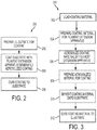
- FIG. 2 is a flowchart of an example powder coating process 200 according to an embodiment of the invention.
- the substrate is prepared 202 for a powder coating process 200 in any of the ways discussed above.
- the preparation can include cleaning the substrate and preparing the surface for the process 200, as discussed above, and can additionally or alternatively include chemically or physically treating the surface to assist the coating process and/or improve the quality of the final coating.
- the substrate is coated 204 with an aerosolized coating of material formed by a filament extension atomizer.
- the filament extension atomizer as discussed above, generates an aerosol of coating material.
- the generated aerosol is at least partially cooled to form a solid, or at least a solid shell about a fluid interior, of the generated droplets.
- the solid or semi-solid droplets are electrostatically charged and deposited across the surface of the substrate to uniformly coat it with the coating material.
- the coated substrate can then be heated 206 to complete the coating process 200.
- the heating process 206 cures and/or melts, or fluidizes, the deposited coating material to form a film, or cohesive coating, across the surface of the substrate. Curing can also include thermal and/or UV energy that cross-links the deposited materials and creates the final coating.
- FIG. 3 illustrates an example powder coating preparation and deposition process 300 according to an embodiment of the invention.
- Powder coating material is loaded 302 into a feed input, where the powder coating material is prepared 304 for the filament extension atomizer.
- Preparing the powder coating can include mixing and blending the various components of the coating material and melting or liquefying them to form a homogenous powder coating material in preparation for aerosolization.
- the powder coating material is required to be in at least a fluidized state for aerosolization by the filament extension atomizer.
- the prepared fluidized, homogeneous powder coating material is transferred to a filament extension atomizer where the powder coating material is aerosolized 306 by counter-rotating rollers of the apparatus.
- the counter-rotating rollers of the filament extension atomizer stretch filaments of the powder coating material between downstream diverging surfaces of the two rollers. The filaments are stretched to a point where the filaments break, forming an aerosol of powder coating material droplets.
- the formed droplets are then be prepared 308 for deposition across the substrate.
- Preparations can include cooling the droplets to solidify them, or at least solidify the outer surface of the droplets. While the outer surface is solidified, the interior material exists in a fluid-like state and having a viscosity. Due to the cooling of the outer surface, the fluid-like interior is also at least partially cooled, resulting in an interior having a high viscosity. As discussed above, maintaining a semi-solid nature of the aerosol droplets reduces the required thermal input that is required during the curing stage to increase the temperature and melt the deposited powderized coating material into a smooth, continuous coating.
- the powder coating material can also be cooled to a uniform temperature where the entire droplet is at a uniform temperature such that the powder is solid enough not to stick or agglomerate with other powder particles or surfaces.
- Additional preparation can include electrostatically charging the formed droplets, as described above.
- the formed droplets of powder coating material are directed towards and deposited onto the substrate 310.
- the electrostatically charged coating material is attracted to the differently charged substrate and covers the substrate in an even and distributed manner.
- the substrate is cured 312 to complete the coating process.
- the coating material is melted to form a continuous film, or coating, across the surface of the substrate.
Landscapes
- Chemical & Material Sciences (AREA)
- Organic Chemistry (AREA)
- Chemical Kinetics & Catalysis (AREA)
- Application Of Or Painting With Fluid Materials (AREA)
- Electrostatic Spraying Apparatus (AREA)
- Coating Apparatus (AREA)
- Pigments, Carbon Blacks, Or Wood Stains (AREA)
Abstract
Description
- Powder coating is an important industrial process that allows for the coating of various materials with a surface film of varying compositions. Metallic pieces or objects often undergo a powder coating process in place of paint, with the deposited coating having various desirable properties, such as color and durability. Typically the coating consists of a plastic, often a thermoplastic, base material that is applied to the substrate as a powder then cured to form a uniform and cohesive coating or film across the substrate.
- The powderized coating material is electrostatically charged and sprayed towards a grounded substrate. The electrostatic potential between the powder and substrate attracts the powder to the substrate surface. Additionally, the use of the electrostatic potential across the entire surface of the substrate. Once coated, the substrate is cured to achieve between the two elements ensures that an even and complete coating is achieved the final coating. The curing process often involves heating the deposited powder until it liquefies to form the film, or coating, across the substrate surface. The cured substrate and coating is then cooled, completing the coating process.
- Powder coating has many benefits as a coating process. Besides the even coat, any residual or overspray of the powder can be collected and reused in future powder coating processes. This means the powder coating process is very efficient as only the necessary amount of powderized coating material is used per piece of coated substrate. However, the desired coating material must first be powderized before the powder coating process can occur. Typically this involves melting a base material and adding any colorants or other desired additives, to form a liquid form of the coating material. The liquid coating material is then cooled into sheets of solid coating material that is then broken up or pulverized to form the coating powder. Once deposited on a substrate and cured, the powdered coating material re-melts to form a liquid that covers the surface of the substrate in a film of the coating material.
- As such, the process of forming the powderized coating and depositing and curing the powderized coating occur as two distinct processes and in two distinct physical locations. Often this means a supplier formulates and produces the powder and a user applies and cures the powder to a desired substrate.
- Forming the powderized coating often requires melting and blending the coating materials which are then cooled and processed into a powder. Once deposited the powder is heated to melt it into the final coating. This means in the conventional methods, the coating material goes through at least two complete heating and cooling cycles to form the final coat on a substrate.
- The powder coating art would greatly benefit from a system and method that is more efficient and requires less energy than the conventional methods.
- According to aspects illustrated herein, there is provided a system and method for coating a substrate using a powder deposition process. Bulk, or raw, coating material, including a base coating material and any colorants or additives, are mixed and heated to a liquid state. The liquid coating material is then aerosolized using a filament extension atomizer to form an aerosol of the coating material. An outer surface of each of the formed aerosol droplets is then prepared to prevent agglomeration of the formed droplets to maintain a powder or powder-like form. Preparing the outer surface of the droplets can include at least partially cooling the droplet to solidify at least an outer surface of each of the droplets of the aerosol to create a powder. The formed powder is then applied to a substrate using an electrostatic deposition process. Once deposited, the powder is cured to the substrate to coat it. The droplets are not required to be completely cooled to a solid state, rather only the outer surface of the droplets is required to be cooled to prevent the droplets from "sticking" or agglomerating. The droplets can maintain an elevated temperature throughout the electrostatic deposition process, as long as the outer surface is prepared to prevent agglomeration. During the curing process in which the deposited material can be melted to form the coating, the length of time required and/or the energy required for the curing process is reduced, as the as the droplets can already be at an elevated temperature during the deposition process. Additionally, the process eliminates cooling and grinding steps that are generally associated with creating power in the first place.
-
-
FIG. 1 is an example powder coating system according to an embodiment of the invention. -
FIG. 2 is an example powder coating process according to an embodiment of the invention. -
FIG. 3 is an example powder coating preparation and deposition process according to an embodiment of the invention. - The disclosed new substrate coating systems and methods integrate the creation of the coating material and the deposition of the created coating material onto a substrate. The integrated nature increases the efficiency and flexibility of the overall system, allowing for rapid modifications of coating properties in an as-needed or on-demand basis as required or desired.
- Powder coating materials are loaded into a coating processing portion of the system where the materials are prepared and aerosolized into a powder, or powder-like, form by a filament extension atomizer. The resulting powder is deposited uniformly onto the substrate material and cured. Curing the deposited powder results in the finished coating over the substrate surface.
- An example
powder coating system 100, according to an embodiment of the invention, is shown inFIG. 1 . Thepowder coating system 100 prepares and deposits the coating material onto a substrate. The coated substrate that is then cured to complete the coating process. Thecoating material 132 is prepared for the coating process as part of thesystem 100. Afeed input 130 is used to mix and prepare thepowder coating material 132 for aerosolization, including melting the material into a fluid. - A
filament extension atomizer 140 generates an aerosol, or droplets, of the fluid powder coating material by stretching the fluid material between tworotating rollers 142. Therollers 142 stretch the fluid powder material between the two diverging surfaces of therollers 142 as the rollers rotate away from each other. The fluid powder coating material pools on an upstream side of a nip, the space between the pair ofrollers 142, and is drawn into the nip as the rollers counter-rotate. On a downstream side, the fluid powder coating material is stretched into a filament between diverging surfaces of the rollers, to which a portion of the fluid still adheres. As the filament is stretched, the filament grows longer and thinner. When the filament reaches a point of instability, the capillary break-up point of the filament, the filament breaks into several drops. As the rollers counter-rotate, continuous formation and break-up of filaments across the surface of therollers 142 generates the aerosol of powder coating material droplets. The aerosol of powder coating material is then directed to further portions of the process for deposition onto the substrate. Alternative forms of afilament extension atomizer 140 can be used, other apparatuses utilize alternate means of creating diverging surfaces, including co-rotating rollers, a single roller and a belt or other linear surface, a system of one or two pistons which stretch a filament between a piston and another piston or other surface and other alternative apparatuses capable of stretching a fluid filament between one or more diverging surface. - As the fluid powder coating material is stretched into filaments, the filaments reach a capillary break up point, and break down into a number of droplets, forming the
aerosol 144 of powder coating material. Theaerosol 144 is directed towards thecoating chamber 122 by a cooling element, anair stream 152. Theair stream 152 cools the aerosol, preparing the formed aerosol droplets for deposition onto the substrate and preventing agglomeration of the droplets. In the example shown, theair stream 152 cools an outer surface of the droplets, reducing the "sticky" nature of the outer surface, making at least the outer surface cool, or solid, enough to prevent agglomeration of the droplets during the deposition process. Preparing the droplets to prevent agglomeration is important otherwise the droplets could adhere to each other or to the substrate being coated without the aid of an electrostatic force. Establishing and utilizing an electrostatic potential between the droplets and the substrate allows the substrate to achieve and even and desired coating of the powder coating material. Theair stream 152 further directs the droplets through thedeposition passage 150. As the aerosol passes through thedeposition passage 150, the droplets can be electrostatically charged. The charged droplets are attracted to the electrically grounded, or oppositely charged,prepared substrate 102 due to the electrostatic potential between the droplets of the aerosol and the substrate. The electrostatic potential between the charged aerosol and thesubstrate 102 attracts a thin layer of coating material to the substrate surface. As the electrostatically charged powder coating material is deposited onto the substrate, the magnitude of the electrostatic potential between the two materials is reduced. The thickness of the coating can be varied and adjusted as desired by varying the magnitude of the electrostatic potential between the droplets and substrate. The greater the electrostatic potential, the more deposited powder coating material is required to reduce electrostatic potential. - The powder coated
substrate 103 is then placed in acuring section 126 that cures the substrate and deposited coating material. Curing the substrate and deposited coating material can include a thermal curing process, a photo-curing process, a chemical curing process, other curing processes and combinations thereof. Curing can cause the deposited coating material to polymerize and cross-link into the final coating. In the example shown, the substrate and deposited coating material are heated, causing the powdered coating material to melt across the surface of thesubstrate 103, coating the surface of the substrate with the coating material. The cured,coated substrate 104 is then cooled, which can complete the coating process. After thecoated substrates 105 are cooled, they are removed from thesystem 100. - The
system 100 integrates the two distinct parts of the overall powder coating process, generation, or creation, of the powderized coating material and the application of the powderized coating onto asubstrate 101. In typical systems, the powder is formed by a supplier and then applied by a user. Thesystem 101 integrates both portions of the process, increasing the overall efficiency of the powder coating process and allowing for quick changes in the coating material and deposition to maintain the quality or other physical properties of the final coating. - The
substrate 101 can be any number of materials suitable for a powder coating process, such as metals and others. In theexample system 100, as shown inFIG. 1 , thesubstrate 101 is placed on a transport system that assists in moving the substrate material through the various sections of thesystem 100. The transport system can be a rail system on which thesubstrate 101 can be mounted onto a bracket or holder and moved through thevarious system 100 sections. The transport system can be automated or the attachedsubstrate 101 can be moved manually along the transport system rails. - Once loaded onto the example transport system, the
substrate 101 enters asubstrate preparation area 110, in which the substrate surface is prepared for the powder coating process. In alternative embodiments, thesubstrate 101 can be moved manually through the whole system, or placed by a user, a machine or others in the various sections. The substrate surface is cleaned of contaminants and debris that can affect the coating process and the final quality of the coating. Chemical and/or mechanical cleaning methods can be used to clean and prepare the substrate surface, including chemical bathes and rinses and/or sandblasting or the like. Theprepared substrate 102 is then ready to undergo the powder coating process and is transferred to the coating andcure section 120. - The aerosolized powder coating material used in the coating process is created within the
system 100, in an as-needed basis. That is, thesystem 100 includes not only the ability to deposit the coating materials onto the substrate, but also the creation of the powdered coating materials. The powdered coating materials are produced within thesystem 100 and are formulated to have the desired properties, such as color and coating composition. The timely nature of the powder coating material creation allows thewhole system 100 to adapt quickly, changing coating formulation and offering the ability to customize the coating formulations. The changing and customization of the coating formulation is done within thesystem 100 rather than having to rely on a powder producer and/or wait for powdered coating material of a desired formulation. -
Powder coating material 132 is fed into afeed input 130 that mixes and prepares the bulk material(s) for aerosolization by thefilament extension atomizer 140. Thepowder coating materials 132 can consist of the coating material and any additional colorants, stabilizers, or additives, as necessary or desired. The coating material can include a thermoplastic or thermoset material. The additives can be included in the formulation of the coating material to alter physical or aesthetic parameters of the final coating. In some example formulations, the additives can be included to strengthen the final coating, making the coating more durable. Colorants can be included in the coating formulation to create a final coating having a desired color or color profile. Stabilizers can be included to assist with the mixing of the various coating formulation components and assist with the aerosol formation, deposition and curing process of the coating. Thepowder coating material 132 can be introduced into thefeed input 130 as pellets or other forms. In some examples, a mix of forms can be used for the powder coating materials, such as pellets of the coating material and a colorant in the form of a powder. - If a user desires to change the formulation of the coating material, the
feed input 130 can be cleared by simply purging and cleaning, if necessary. The powder coating material is heated within thefeed input 130 to form a liquid that can be formed into the aerosolized coating material using a filament extension atomizer. Since the coating material is a liquid, or can be heated to melt into a liquid state, within thefeed input 130, clearing the feed input is a relatively simple process of purging residual or undesired coating material. This material can be cooled to re-set the material in a solid form that can then be reprocessed through thefeed input 130 to form future coating material. Once thefeed input 130 is cleared, new powder coating material to create a different, desired formulation of coating material can be processed through theapparatus 130. Alternatively, additives or other additional powder coating materials can be added to the already created coating formulation to alter the formulation to a desired one. - In an example, a twin screw extruder is employed as the
feed input 130. Thetwin screw extruder 130 uses a pair counter-rotating helical screws that are aligned angularly to each other such that the ends of the pair of screws terminate towards a point. The helical pattern of the screws drives inserted materials down the length of the screws. As the separation between the two screws narrows, due to the angular arrangement, the inserted materials are mechanically processed, heating and mixing the inserted material between the pair of helical screws. Various screw designs can be implemented depending on the material that perform a combination of mechanical and thermal processing such as heating, cooling, compressing, shearing, or shaping.Powder coating materials 132, the materials that will comprise the deposited coating, are fed into thetwin screw extruder 130 which heats, mixes and fluidizes the bulk coating materials in preparation for aerosolization by thefilament extension atomizer 140. The twin screw heats and melts the bulk materials into a homogeneous liquid, or semi-liquid, extrusion that is fed into thefilament extension atomizer 140. Alternative forms of afeed input 130 can be used, such as a heated mixing apparatus, or other apparatus capable of melting and homogenizing thepowder coating materials 132. Thefeed input 130 is capable of preparing thepowder coating materials 132 for use with afilament extension atomizer 140. - The fluid powder coating material is introduced into a
filament extension atomizer 140. In this example, the filament extension atomizer includescounter-rotating rollers 142. As one or both of therollers 142 rotates, a thin layer of fluid powder coating material is deposited across its surface. At a nip, the point at which therollers 142 are closest, the counter-rotating roller engages the layer of fluid powder coating material. As therollers 142 counter-rotate, the engaged fluid powder coating material is stretched, on a downstream side, between the diverging surfaces of therollers 142. The engaged fluid powder coating material is stretched until it forms filament(s) of fluid powder coating material between the diverging surfaces of the two rollers. As therollers 142 continue to rotate the filament is stretched to a point of instability, a capillary break-up point, causing the filament to breakdown into a plurality of droplets. The repeated formation and breakdown of the filaments across the rollers 142forms an aerosol ofcoating material 144. - The filament extension atomizer can include additional features, such as heaters, fans, baffles or other mechanical elements that assist with the proper aerosolization of the fluid powder coating material. In an example embodiment, the interior of the filament extension atomizer can be heated, internally or externally, in order to maintain the fluidity of the powder coating material as it is aerosolized.
- Many factors can affect the quality of the coating, such as environmental factors or other system factors. The integration of the
feed input 130 and thefilament extension atomizer 140 in-line with thepowder coating system 100 increases the efficiency of thesystem 100. In theexample system 100, the coating can be continuously modified to account for changes in the affecting factors, thus maintaining the desired quality of the coating. This can include the altering of the composition of the powder coating material to compensate for various environmental or other factors or to correct errors a user, a machine or others detect in the final coating. Further, the integrated nature allows for the rapid change of coating materials, stabilizers, colorants or other additives by simply adding the necessary components to alter the composition of the coating or creating and aerosolizing a new coating formulation. A complete change of powder coating material can be done by purging or flushing residual powder material from thefeed input 130 andfilament extension atomizer 140, and a new composition of powder coating materials can be introduced. The new formulation can be desired based on the substrate material and adherence of the coating, a color of the coating, strength of the coating, or other qualities of the powder coating as desired. - Once formed, the aerosol, droplets, of
powder coating material 144 is directed from the filament extension atomizer and into adeposition passage 150. Thedeposition passage 150 connects thefeed input 130 and thefilament extension atomizer 140 tocoating chamber 122 in a sequential, in-line arrangement. The aerosol can be directed due to the imparted kinetic energy created by the atomizer, an air current created by the rotation of the rollers or an introducedair stream 152 that directs the aerosol from the filament extension atomizer. - An
airstream 152 is directed through thepassage 150 to carry the aerosol towards thecoating area 122. In addition to directing theaerosol 144 through thepassage 150, theairstream 152 cools the formed droplets of coating material. The cooling of the droplets prepares the droplets for the powder coating process by solidifying at least some portion of the droplets. The preparation, in this example solidification, of the outer surface of the droplets prevents the droplets from adhering, or agglomerating, to one another during the deposition process. At minimum the droplets are cooled such that a solid surface is formed on the outside of the droplets, however they can also be cooled such that the entire droplet is solid. The now at least semi-solidified prepared droplets can be directed through the remainder of thepassage 150 and processed further for the deposition stage. - A droplet sizing mechanism or filter can be placed within the
passage 150 to permit droplets of a selected size and/or to exclude oversized droplets from thecoating area 122. Alternatively, theair stream 152 can be used to sort the droplets based on size, such that the heavier droplets do not have the necessary momentum to flow through the passage because of their weight when directed by the airstream and instead fall out of theair stream 152 leaving the smaller droplets to continue through the passage. - The
prepared substrate 102 is placed in thecoating area 122 and electrically grounded, or charged, in preparation for the powder coating process. In the example embodiment, the transporter system can be grounded and electrically connected to the substrate, by a simple piece of copper wire or other means, thereby grounding the substrate. The aerosol ofcoating material 144 formed by thefilament extension atomizer 140 is directed towards the substrate byvarious sprayers 124. As the coating material exits thesprayers 124, it is electrostatically charged. Anelectrostatic charging apparatus 124 can be used to charge the dispensed aerosolized coating material by directing the aerosol through a high voltage electrical field generated at the point of dispensing. Alternative dispensers can be used in thecoating chamber 122 to dispense the generated aerosol of coating material in preparation for deposition onto the substrate surface. The electrostatically charged coating material is attracted and adheres to the groundedsubstrate 102 due to the charge difference, electrostatic potential, between the powder coating material and the grounded substrate. A number ofsprayers 124 can be employed within thecoating area 122 to ensure an even and equal coating of material across the substrate surface. - Any overspray or excess coating material can be collected and used as bulk coating material for later coating processes. The collected coating material can be fed directly back through
feed input 130, reintroduced into theairstream 150, or collected and held for future coating processes. - The
coated substrate 103 is then transported to acuring area 126 of thesystem 100. The curing area provides the necessary environment in which to cure the powder coating material to the substrate. Curing the powder coating material can include polymerizing and cross-linking the deposited coating material to form a cohesive layer. In the example shown, the curing area heats the coating material, a thermoplastic, to melt it, which causes the coating to bond to the substrate and form a cohesive layer. The heating can also be used to thermally cure a thermoset material. Alternatively, UV light can be used to cure the material, either alone or in combination with thermal energy. - In the
example system 100 ofFIG. 1 , the coating material is deposited onto the substrate surface at a surface temperature below the melting point of the material, but above room temperature. The outer surfaces of the droplets are prepared for the powder coating process. Preparing the droplets can include cooling the droplets so that they are at least partially solid and may be fully solid. During the curing process, the amount of thermal energy required to melt the deposited coating materials into the finished coating is reduced since the materials already have a considerable amount of thermal energy above that of room temperature. The reduced thermal energy required per unit substrate during the curing process, or stage, increases the efficiency and economy of thesystem 100. - In a traditional powder production process, powder coating material is first heated or melted and blended to a desired formulation. The material is then cooled to a solid form and powderized. The material is usually powderized by a combination of milling, cutting, and grinding operations that often occur at a temperature below room temperature to increase the uniformity and quality of the powder. The powderized coating material is applied to a substrate and cured, or heated again, to melt the deposited materials into an even coating or film across the substrate surface. In the example systems outlined, the creation of the powderized coating material and deposition of the said material is contained in a single system.
- The substrate and/or
coating area 122 can be heated during the powder deposition process to help maintain the formed droplets of coating material at a specific temperature or within a specific temperature range. Additionally, preheating the substrate can decrease the time required to heat the coating after application and often can increase the quality and consistency of a coating. - In the
system 100, the powder coating materials are heated, blended and aerosolized to form an aerosol of coating material. The aerosolized coating material is cooled sufficiently or in a manner to prevent agglomeration of the droplets. Cooling can include cooling the drops such that a solid, or nearly solid, shell exists about the outer surface of each of the droplets of aerosolized coating material. The solid surface character of the droplets prevents the droplets from agglomerating or sticking to other surfaces. The semi-cooled aerosol is deposited onto a substrate and cured. The curing in thesystem 100 can take less time and/or less energy than conventional methods that require heating the material from a cooled, solid state into a fluid state, since the deposited material of thesystem 100 is already at an elevated temperature. Reheating and melting the solid exterior surface of the deposited material is the required energy input for the curing process of thesystem 100. - Referring again to
FIG. 1 , the cured,coated substrate 104 emerges from the curingarea 126 and is then cooled to a temperature that transforms the coating into a solid state, or at least solid enough that the quality of the coating is not compromised by handling. The temperature can be a range of temperatures and the degree of solidness of the coating can also be a range. Once the coated substrates reach a state in which they are solid enough to be handled, they can be removed from thesystem 100 ascoated substrates 105. - The substrate coating process using the
system 100 can be repeated as often as necessary to coat the desired unit of substrates. Additional coating material is created by adding more or having a continuous feed of powder coating materials into thefeed input 130. Changing the formulation of the coating material can be easily and readily done in the manners discussed above since the creation of the powderized coating material is performed by the in-line,integrated feed input 130 andfilament extension atomizer 140. As an example, the color of a coated substrate can be changed readily as material is moved through the system. With sufficient planning ahead, the color can be altered in a continuous or near continuous manner so that no purging of the powder production system, feedinput 130,atomizer 140, ordroplet handling system 150, is required. - In alternative embodiments, one or more pairs of
feed input 130 andfilament extension atomizer 140 can be integrated within thesystem 100. Each pair ofdevices system 100 able to select which of the pair, and the coating formulation, is the active one dispensed into thecoating area 122. - In a further alternative, the pair of
devices devices devices -
FIG. 2 is a flowchart of an examplepowder coating process 200 according to an embodiment of the invention. Initially, the substrate is prepared 202 for apowder coating process 200 in any of the ways discussed above. The preparation can include cleaning the substrate and preparing the surface for theprocess 200, as discussed above, and can additionally or alternatively include chemically or physically treating the surface to assist the coating process and/or improve the quality of the final coating. - Once prepared, the substrate is coated 204 with an aerosolized coating of material formed by a filament extension atomizer. The filament extension atomizer, as discussed above, generates an aerosol of coating material. The generated aerosol is at least partially cooled to form a solid, or at least a solid shell about a fluid interior, of the generated droplets. The solid or semi-solid droplets are electrostatically charged and deposited across the surface of the substrate to uniformly coat it with the coating material.
- The coated substrate can then be heated 206 to complete the
coating process 200. Theheating process 206 cures and/or melts, or fluidizes, the deposited coating material to form a film, or cohesive coating, across the surface of the substrate. Curing can also include thermal and/or UV energy that cross-links the deposited materials and creates the final coating. -
FIG. 3 illustrates an example powder coating preparation anddeposition process 300 according to an embodiment of the invention. Powder coating material is loaded 302 into a feed input, where the powder coating material is prepared 304 for the filament extension atomizer. Preparing the powder coating can include mixing and blending the various components of the coating material and melting or liquefying them to form a homogenous powder coating material in preparation for aerosolization. The powder coating material is required to be in at least a fluidized state for aerosolization by the filament extension atomizer. - The prepared fluidized, homogeneous powder coating material is transferred to a filament extension atomizer where the powder coating material is aerosolized 306 by counter-rotating rollers of the apparatus. The counter-rotating rollers of the filament extension atomizer stretch filaments of the powder coating material between downstream diverging surfaces of the two rollers. The filaments are stretched to a point where the filaments break, forming an aerosol of powder coating material droplets.
- The formed droplets are then be prepared 308 for deposition across the substrate. Preparations can include cooling the droplets to solidify them, or at least solidify the outer surface of the droplets. While the outer surface is solidified, the interior material exists in a fluid-like state and having a viscosity. Due to the cooling of the outer surface, the fluid-like interior is also at least partially cooled, resulting in an interior having a high viscosity. As discussed above, maintaining a semi-solid nature of the aerosol droplets reduces the required thermal input that is required during the curing stage to increase the temperature and melt the deposited powderized coating material into a smooth, continuous coating. The powder coating material can also be cooled to a uniform temperature where the entire droplet is at a uniform temperature such that the powder is solid enough not to stick or agglomerate with other powder particles or surfaces. Additional preparation can include electrostatically charging the formed droplets, as described above.
- The formed droplets of powder coating material are directed towards and deposited onto the
substrate 310. The electrostatically charged coating material is attracted to the differently charged substrate and covers the substrate in an even and distributed manner. - Once the substrate has been coated in the aerosolized coating material, the substrate is cured 312 to complete the coating process. During the
curing stage 312, the coating material is melted to form a continuous film, or coating, across the surface of the substrate. - It will be appreciated that variants of the above-disclosed and other features and functions, or alternatives thereof, may be combined into many other different systems or applications. Various presently unforeseen or unanticipated alternatives, modifications, variations, or improvements therein may be subsequently made by those skilled in the art which are also intended to be encompassed by the following claims.
Claims (10)
- A powder coating system, comprising:a feed input configured to receive a powder coating material and to melt the powder coating material into a homogenous fluid of powder coating material;a filament extension atomizer positioned in-line with the feed input, the filament extension atomize configured to receive the melted homogenous fluid of powder coating material and to atomize to homogenous fluid of powder coating material into multiple droplets of powder coating material;a cooling element configured to cool the droplets of powder coating material to a processing temperature that prevents the droplets from agglomerating to each other; anda deposition passage positioned in-line with the filament extension atomizer, the deposition passage configured to direct at least a portion of the cooled droplets towards the substrate.
- The powder coating system of claim 1, further including a substrate preparation area configured to treat the substrate before the at least a portion of the cooled droplets are directed towards the substrate.
- The powder coating system of claim 1, wherein the feed input is a twin screw apparatus.
- The powder coating system of claim 1, wherein the powder coating material is one of a thermoplastic or a thermoset.
- The powder coating system of claim 1, wherein the feed input is further configured to receive at least one of a colorant, a stabilizer and an additive, and to mix at least one of the colorant, the stabilizer and the additive into the homogenous fluid of powder coating material.
- A method of powder coating a substrate, comprising:receiving a powder coating material into a feed input;using the feed input, melting the powder coating material into a homogeneous fluid of powder coating material;receiving the homogeneous fluid of powder coating material into a filament extension atomizer positioned in-line with the feed input;atomizing, with the filament extension atomizer, the received homogeneous fluid of powder coating material into multiple droplets of powder coating material;cooling the droplets of powder coating material to a processing temperature that prevents the droplets from agglomerating; anddirecting the cooled droplets through a deposition passage positioned in-line with the filament extension atomizer, the deposition passage configured to direct at least a portion of the cooled droplets towards a substrate.
- The method of powder coating a substrate of claim 6, further including preparing the substrate surface for deposition of cooled droplets of powder coating material.
- The method of powder coating a substrate of claim 6, further including heating the substrate surface in preparation for deposition of the aerosolized coating material
- The method of powder coating a substrate of claim 6, wherein the feed input is further configured to receive at least one of a colorant, a stabilizer and an additive, and to mix the received at least one of the colorant, the stabilizer and the additive into the homogeneous fluid of powder coating material.
- The method of powder coating a substrate of claim 6, wherein the feed input is a twin screw apparatus.
Applications Claiming Priority (1)
| Application Number | Priority Date | Filing Date | Title |
|---|---|---|---|
| US14/997,915 US9993839B2 (en) | 2016-01-18 | 2016-01-18 | System and method for coating a substrate |
Publications (2)
| Publication Number | Publication Date |
|---|---|
| EP3192586A1 true EP3192586A1 (en) | 2017-07-19 |
| EP3192586B1 EP3192586B1 (en) | 2019-04-10 |
Family
ID=57914692
Family Applications (1)
| Application Number | Title | Priority Date | Filing Date |
|---|---|---|---|
| EP17151186.8A Active EP3192586B1 (en) | 2016-01-18 | 2017-01-12 | System and method for coating a substrate |
Country Status (3)
| Country | Link |
|---|---|
| US (2) | US9993839B2 (en) |
| EP (1) | EP3192586B1 (en) |
| JP (1) | JP6736485B2 (en) |
Families Citing this family (5)
| Publication number | Priority date | Publication date | Assignee | Title |
|---|---|---|---|---|
| US9993839B2 (en) | 2016-01-18 | 2018-06-12 | Palo Alto Research Center Incorporated | System and method for coating a substrate |
| US11246997B2 (en) | 2018-09-25 | 2022-02-15 | Palo Alto Research Center Incorporated | Handheld filament extension atomizer for precision delivery of drugs and therapeutics |
| JP7310781B2 (en) * | 2020-11-06 | 2023-07-19 | 株式会社豊田中央研究所 | Coating film, manufacturing method thereof, and powder coating apparatus |
| US20220380928A1 (en) * | 2021-05-29 | 2022-12-01 | Nissan North America, Inc. | Method and system of powder coating a vehicle component |
| US11909052B2 (en) | 2021-06-30 | 2024-02-20 | Xerox Corporation | Fabrication of membrane electrode assembly with filament extension atomizer spray |
Citations (3)
| Publication number | Priority date | Publication date | Assignee | Title |
|---|---|---|---|---|
| WO1993013897A1 (en) * | 1992-01-16 | 1993-07-22 | Sprayforming Developments Ltd. | Process for producing a spray of metal powder |
| US5609919A (en) * | 1994-04-21 | 1997-03-11 | Altamat Inc. | Method for producing droplets |
| US20150190824A1 (en) * | 2014-01-08 | 2015-07-09 | United Technologies Corporation | Cold spray systems with in-situ powder manufacturing |
Family Cites Families (56)
| Publication number | Priority date | Publication date | Assignee | Title |
|---|---|---|---|---|
| US2291046A (en) | 1942-07-28 | Arrangement for burning liquid fuel | ||
| US2551582A (en) | 1943-08-27 | 1951-05-08 | Chester F Carlson | Method of printing and developing solvent images |
| US3052213A (en) | 1958-12-17 | 1962-09-04 | Ibm | Electrostatic printer apparatus for printing with liquid ink |
| DE1302344B (en) | 1961-02-06 | |||
| DE1164829B (en) | 1961-04-26 | 1964-03-05 | Bayer Ag | Process for the electrophotographic production of images with liquid aerosols |
| CH413018A (en) | 1963-04-30 | 1966-05-15 | Du Pont | Thermoelectric generator |
| US3926114A (en) | 1967-06-30 | 1975-12-16 | Walter E S Matuschke | Rotary lithographic printing press with ink and dampening fluid separator |
| US3702258A (en) | 1969-03-05 | 1972-11-07 | Eastman Kodak Co | Web treatment method |
| US3626833A (en) | 1969-06-09 | 1971-12-14 | Addressograph Multigraph | Liquid developing apparatus |
| US3977323A (en) | 1971-12-17 | 1976-08-31 | Electroprint, Inc. | Electrostatic printing system and method using ions and liquid aerosol toners |
| US3649829A (en) | 1970-10-06 | 1972-03-14 | Atomic Energy Commission | Laminar flow cell |
| US3779166A (en) | 1970-12-28 | 1973-12-18 | Electroprint Inc | Electrostatic printing system and method using ions and toner particles |
| US3717875A (en) | 1971-05-04 | 1973-02-20 | Little Inc A | Method and apparatus for directing the flow of liquid droplets in a stream and instruments incorporating the same |
| US3873025A (en) | 1974-05-06 | 1975-03-25 | Stora Kopparbergs Bergslags Ab | Method and apparatus for atomizing a liquid medium and for spraying the atomized liquid medium in a predetermined direction |
| US4034670A (en) | 1975-03-24 | 1977-07-12 | Rockwell International Corporation | Dampening device for lithographic printing press |
| US4222059A (en) | 1978-12-18 | 1980-09-09 | Xerox Corporation | Ink jet multiple field electrostatic lens |
| US4384296A (en) | 1981-04-24 | 1983-05-17 | Xerox Corporation | Linear ink jet deflection method and apparatus |
| ES2043289T3 (en) | 1989-09-25 | 1993-12-16 | Schneider Usa Inc | THE EXTRUSION OF MULTIPLE LAYERS AS A PROCEDURE FOR MAKING ANGIOPLASTY BALLS. |
| US5103763A (en) * | 1989-12-08 | 1992-04-14 | International Business Machines Corporation | Apparatus for formation and electrostatic deposition of charged droplets |
| US5204697A (en) | 1990-09-04 | 1993-04-20 | Xerox Corporation | Ionographic functional color printer based on Traveling Cloud Development |
| US5314119A (en) | 1992-04-20 | 1994-05-24 | Latanick Equipment, Inc. | Method and apparatus for applying thin coatings of fluid droplets |
| US5746844A (en) | 1995-09-08 | 1998-05-05 | Aeroquip Corporation | Method and apparatus for creating a free-form three-dimensional article using a layer-by-layer deposition of molten metal and using a stress-reducing annealing process on the deposited metal |
| US6506438B2 (en) | 1998-12-15 | 2003-01-14 | E Ink Corporation | Method for printing of transistor arrays on plastic substrates |
| BR0015845B1 (en) | 1999-11-26 | 2009-05-05 | applicator and method for applying a fluid to a surface. | |
| US6622335B1 (en) | 2000-03-29 | 2003-09-23 | Lam Research Corporation | Drip manifold for uniform chemical delivery |
| US6576861B2 (en) * | 2000-07-25 | 2003-06-10 | The Research Foundation Of State University Of New York | Method and apparatus for fine feature spray deposition |
| DE10108717C1 (en) | 2001-02-23 | 2002-07-11 | Bosch Gmbh Robert | Apparatus for removing electric charge from a plastic sheet, paper web or polymer fibers, comprises a plasma generator producing plasma containing charged particles and rollers which feed sheet through the region containing plasma |
| US20040050701A1 (en) | 2002-09-13 | 2004-03-18 | Mcentee John Francis | Electrostatically guiding ionized droplets in chemical array fabrication |
| WO2004028707A2 (en) | 2002-09-25 | 2004-04-08 | Koninklijke Philips Electronics N.V. | Method of electrostatic deposition |
| KR100519343B1 (en) | 2003-07-02 | 2005-10-07 | 엘지전자 주식회사 | wearable cooler |
| US7083830B2 (en) | 2003-10-02 | 2006-08-01 | E. I. Dupont De Nemours And Company | Electrostatically-assisted high-speed rotary application process for the production of special effect base coat/clear coat two-layer coatings |
| US20050202270A1 (en) * | 2004-03-10 | 2005-09-15 | Skoog Andrew J. | Powder coating of gas turbine engine components |
| EP1625893A1 (en) | 2004-08-10 | 2006-02-15 | Konica Minolta Photo Imaging, Inc. | Spray coating method, spray coating device and inkjet recording sheet |
| US7938341B2 (en) | 2004-12-13 | 2011-05-10 | Optomec Design Company | Miniature aerosol jet and aerosol jet array |
| DE102005022308B4 (en) | 2005-05-13 | 2007-03-22 | Eos Gmbh Electro Optical Systems | Apparatus and method for manufacturing a three-dimensional object with a heated powder coating material build-up material |
| JP2008227178A (en) | 2007-03-13 | 2008-09-25 | Sumitomo Chemical Co Ltd | Thermoelectric conversion module substrate and thermoelectric conversion module |
| TWI338390B (en) | 2007-07-12 | 2011-03-01 | Ind Tech Res Inst | Flexible thermoelectric device and manufacturing method thereof |
| TWI482662B (en) | 2007-08-30 | 2015-05-01 | 阿普托麥克股份有限公司 | Mechanically integrated and tightly coupled print heads and spray sources |
| TW200933940A (en) | 2007-12-28 | 2009-08-01 | Basf Se | Extrusion process for preparing improved thermoelectric materials |
| TWI723953B (en) | 2008-03-05 | 2021-04-11 | 美國伊利諾大學理事會 | Stretchable and foldable electronic devices |
| EP2131406A1 (en) | 2008-06-02 | 2009-12-09 | Nederlandse Organisatie voor toegepast- natuurwetenschappelijk onderzoek TNO | A method for manufacturing a thermoelectric generator, a wearable thermoelectric generator and a garment comprising the same |
| US9163883B2 (en) | 2009-03-06 | 2015-10-20 | Kevlin Thermal Technologies, Inc. | Flexible thermal ground plane and manufacturing the same |
| JP5573046B2 (en) | 2009-08-24 | 2014-08-20 | 富士通株式会社 | Film forming apparatus and film forming method |
| US20110150036A1 (en) | 2009-12-21 | 2011-06-23 | Electronics And Telecommunications Research Institute | Flexible thermoelectric generator, wireless sensor node including the same and method of manufacturing the same |
| EP2498310A3 (en) | 2011-03-11 | 2013-12-11 | Imec | Thermoelectric textile |
| US8720370B2 (en) | 2011-04-07 | 2014-05-13 | Dynamic Micro System Semiconductor Equipment GmbH | Methods and apparatuses for roll-on coating |
| JP5656295B2 (en) | 2011-04-22 | 2015-01-21 | パナソニックIpマネジメント株式会社 | Thermoelectric conversion module and manufacturing method thereof |
| US9021948B2 (en) | 2011-04-27 | 2015-05-05 | Xerox Corporation | Environmental control subsystem for a variable data lithographic apparatus |
| US20130087180A1 (en) | 2011-10-10 | 2013-04-11 | Perpetua Power Source Technologies, Inc. | Wearable thermoelectric generator system |
| US9132645B2 (en) | 2012-11-29 | 2015-09-15 | Palo Alto Research Center Incorporated | Pulsating heat pipe spreader for ink jet printer |
| US10016777B2 (en) * | 2013-10-29 | 2018-07-10 | Palo Alto Research Center Incorporated | Methods and systems for creating aerosols |
| US9962673B2 (en) * | 2013-10-29 | 2018-05-08 | Palo Alto Research Center Incorporated | Methods and systems for creating aerosols |
| US10933636B2 (en) * | 2013-12-06 | 2021-03-02 | Palo Alto Research Center Incorporated | Print head design for ballistic aerosol marking with smooth particulate injection from an array of inlets into a matching array of microchannels |
| US20150197063A1 (en) | 2014-01-12 | 2015-07-16 | Zohar SHINAR | Device, method, and system of three-dimensional printing |
| US10400119B2 (en) | 2015-05-07 | 2019-09-03 | Ehsan Toyserkani | Method and apparatus for aerosol-based three-dimensional (3D) printing of flexible graphene electronic devices |
| US9993839B2 (en) | 2016-01-18 | 2018-06-12 | Palo Alto Research Center Incorporated | System and method for coating a substrate |
-
2016
- 2016-01-18 US US14/997,915 patent/US9993839B2/en active Active
-
2017
- 2017-01-10 JP JP2017002159A patent/JP6736485B2/en not_active Expired - Fee Related
- 2017-01-12 EP EP17151186.8A patent/EP3192586B1/en active Active
-
2018
- 2018-05-16 US US15/981,710 patent/US10112213B2/en active Active
Patent Citations (3)
| Publication number | Priority date | Publication date | Assignee | Title |
|---|---|---|---|---|
| WO1993013897A1 (en) * | 1992-01-16 | 1993-07-22 | Sprayforming Developments Ltd. | Process for producing a spray of metal powder |
| US5609919A (en) * | 1994-04-21 | 1997-03-11 | Altamat Inc. | Method for producing droplets |
| US20150190824A1 (en) * | 2014-01-08 | 2015-07-09 | United Technologies Corporation | Cold spray systems with in-situ powder manufacturing |
Also Published As
| Publication number | Publication date |
|---|---|
| US20170203326A1 (en) | 2017-07-20 |
| JP6736485B2 (en) | 2020-08-05 |
| EP3192586B1 (en) | 2019-04-10 |
| JP2017131880A (en) | 2017-08-03 |
| US9993839B2 (en) | 2018-06-12 |
| US10112213B2 (en) | 2018-10-30 |
| US20180257103A1 (en) | 2018-09-13 |
Similar Documents
| Publication | Publication Date | Title |
|---|---|---|
| US10112213B2 (en) | System and method for coating a substrate | |
| RU2343169C2 (en) | Powder for fast prototype creation and method of its obtaining | |
| US5562979A (en) | Method of forming a moulding by dual injection and a moulding so formed | |
| JPS6090078A (en) | Inpact resistant moisture impervious resin film and coating method thereof | |
| DE3225844A1 (en) | Process and apparatus for applying layers of thermoplastic plastics or hot melt adhesives | |
| DE2349318A1 (en) | METHOD AND DEVICE FOR ELECTROSTATIC COATING OF OBJECTS | |
| TWI708691B (en) | Additive deposition method | |
| JP7403522B2 (en) | Manufacturing processes and systems for manufacturing 3D printed drug delivery products | |
| JPH09302283A (en) | Electrostatically chargeable plastic powder coatings for triboelectrostatic coating and triboelectrostatic coating methods | |
| US20140295095A1 (en) | In-Line Powder Coating of Non-Conductive Profiles Produced in a Continuous Forming Process such as Pultrusion and Extrusion | |
| CA2635533A1 (en) | Granulation-coating machine for glass fiber granules | |
| US11267164B2 (en) | Creating aligned and oriented fiber reinforced polymer composites | |
| EP2994242B1 (en) | Spray-coating method | |
| JP6244354B2 (en) | Method for producing powder from granular thermoplastic material and apparatus for producing chips from powdered thermoplastic material | |
| Claase et al. | Powder coatings and the effects of particle size | |
| JP3368593B2 (en) | How to apply thermosetting paint | |
| RU2353705C2 (en) | Method ofgas-dynamic sputtering of powder materials and facility for its realisation | |
| WO2019180190A1 (en) | Apparatus for conveying and metering powder, apparatus for producing a layered structure on a surface region of a component, sheet-like heating element and method for producing a sheet-like heating element | |
| US11186025B2 (en) | Method and apparatus for producing fibre-reinforced plastic mouldings | |
| JP2003164796A (en) | Continuous covering method with network polymer | |
| JP2002136956A (en) | How to Recycle Powder Paint Waste | |
| JP2003055609A (en) | Powder coating and manufacturing method of powder coating | |
| EP2117694A1 (en) | Process and apparatus for coating pulverulent material and coated material and use thereof | |
| WO2001085360A2 (en) | Coating process | |
| EP0900672B1 (en) | Process for painting various objects and artefacts with powder paints, painted products obtained thereby and related apparatus |
Legal Events
| Date | Code | Title | Description |
|---|---|---|---|
| PUAI | Public reference made under article 153(3) epc to a published international application that has entered the european phase |
Free format text: ORIGINAL CODE: 0009012 |
|
| STAA | Information on the status of an ep patent application or granted ep patent |
Free format text: STATUS: THE APPLICATION HAS BEEN PUBLISHED |
|
| AK | Designated contracting states |
Kind code of ref document: A1 Designated state(s): AL AT BE BG CH CY CZ DE DK EE ES FI FR GB GR HR HU IE IS IT LI LT LU LV MC MK MT NL NO PL PT RO RS SE SI SK SM TR |
|
| AX | Request for extension of the european patent |
Extension state: BA ME |
|
| STAA | Information on the status of an ep patent application or granted ep patent |
Free format text: STATUS: REQUEST FOR EXAMINATION WAS MADE |
|
| 17P | Request for examination filed |
Effective date: 20180119 |
|
| RBV | Designated contracting states (corrected) |
Designated state(s): AL AT BE BG CH CY CZ DE DK EE ES FI FR GB GR HR HU IE IS IT LI LT LU LV MC MK MT NL NO PL PT RO RS SE SI SK SM TR |
|
| RIC1 | Information provided on ipc code assigned before grant |
Ipc: B01J 2/02 20060101ALI20180920BHEP Ipc: B05B 5/16 20060101AFI20180920BHEP Ipc: B05B 5/08 20060101ALN20180920BHEP Ipc: B05B 7/18 20060101ALI20180920BHEP |
|
| GRAP | Despatch of communication of intention to grant a patent |
Free format text: ORIGINAL CODE: EPIDOSNIGR1 |
|
| STAA | Information on the status of an ep patent application or granted ep patent |
Free format text: STATUS: GRANT OF PATENT IS INTENDED |
|
| INTG | Intention to grant announced |
Effective date: 20181029 |
|
| GRAS | Grant fee paid |
Free format text: ORIGINAL CODE: EPIDOSNIGR3 |
|
| GRAA | (expected) grant |
Free format text: ORIGINAL CODE: 0009210 |
|
| STAA | Information on the status of an ep patent application or granted ep patent |
Free format text: STATUS: THE PATENT HAS BEEN GRANTED |
|
| AK | Designated contracting states |
Kind code of ref document: B1 Designated state(s): AL AT BE BG CH CY CZ DE DK EE ES FI FR GB GR HR HU IE IS IT LI LT LU LV MC MK MT NL NO PL PT RO RS SE SI SK SM TR |
|
| REG | Reference to a national code |
Ref country code: GB Ref legal event code: FG4D |
|
| REG | Reference to a national code |
Ref country code: CH Ref legal event code: EP Ref country code: AT Ref legal event code: REF Ref document number: 1117979 Country of ref document: AT Kind code of ref document: T Effective date: 20190415 |
|
| REG | Reference to a national code |
Ref country code: IE Ref legal event code: FG4D |
|
| REG | Reference to a national code |
Ref country code: DE Ref legal event code: R096 Ref document number: 602017003108 Country of ref document: DE |
|
| REG | Reference to a national code |
Ref country code: NL Ref legal event code: MP Effective date: 20190410 |
|
| REG | Reference to a national code |
Ref country code: LT Ref legal event code: MG4D |
|
| REG | Reference to a national code |
Ref country code: AT Ref legal event code: MK05 Ref document number: 1117979 Country of ref document: AT Kind code of ref document: T Effective date: 20190410 |
|
| PG25 | Lapsed in a contracting state [announced via postgrant information from national office to epo] |
Ref country code: NL Free format text: LAPSE BECAUSE OF FAILURE TO SUBMIT A TRANSLATION OF THE DESCRIPTION OR TO PAY THE FEE WITHIN THE PRESCRIBED TIME-LIMIT Effective date: 20190410 |
|
| PG25 | Lapsed in a contracting state [announced via postgrant information from national office to epo] |
Ref country code: ES Free format text: LAPSE BECAUSE OF FAILURE TO SUBMIT A TRANSLATION OF THE DESCRIPTION OR TO PAY THE FEE WITHIN THE PRESCRIBED TIME-LIMIT Effective date: 20190410 Ref country code: AL Free format text: LAPSE BECAUSE OF FAILURE TO SUBMIT A TRANSLATION OF THE DESCRIPTION OR TO PAY THE FEE WITHIN THE PRESCRIBED TIME-LIMIT Effective date: 20190410 Ref country code: SE Free format text: LAPSE BECAUSE OF FAILURE TO SUBMIT A TRANSLATION OF THE DESCRIPTION OR TO PAY THE FEE WITHIN THE PRESCRIBED TIME-LIMIT Effective date: 20190410 Ref country code: HR Free format text: LAPSE BECAUSE OF FAILURE TO SUBMIT A TRANSLATION OF THE DESCRIPTION OR TO PAY THE FEE WITHIN THE PRESCRIBED TIME-LIMIT Effective date: 20190410 Ref country code: LT Free format text: LAPSE BECAUSE OF FAILURE TO SUBMIT A TRANSLATION OF THE DESCRIPTION OR TO PAY THE FEE WITHIN THE PRESCRIBED TIME-LIMIT Effective date: 20190410 Ref country code: FI Free format text: LAPSE BECAUSE OF FAILURE TO SUBMIT A TRANSLATION OF THE DESCRIPTION OR TO PAY THE FEE WITHIN THE PRESCRIBED TIME-LIMIT Effective date: 20190410 Ref country code: NO Free format text: LAPSE BECAUSE OF FAILURE TO SUBMIT A TRANSLATION OF THE DESCRIPTION OR TO PAY THE FEE WITHIN THE PRESCRIBED TIME-LIMIT Effective date: 20190710 Ref country code: PT Free format text: LAPSE BECAUSE OF FAILURE TO SUBMIT A TRANSLATION OF THE DESCRIPTION OR TO PAY THE FEE WITHIN THE PRESCRIBED TIME-LIMIT Effective date: 20190910 |
|
| PG25 | Lapsed in a contracting state [announced via postgrant information from national office to epo] |
Ref country code: PL Free format text: LAPSE BECAUSE OF FAILURE TO SUBMIT A TRANSLATION OF THE DESCRIPTION OR TO PAY THE FEE WITHIN THE PRESCRIBED TIME-LIMIT Effective date: 20190410 Ref country code: RS Free format text: LAPSE BECAUSE OF FAILURE TO SUBMIT A TRANSLATION OF THE DESCRIPTION OR TO PAY THE FEE WITHIN THE PRESCRIBED TIME-LIMIT Effective date: 20190410 Ref country code: GR Free format text: LAPSE BECAUSE OF FAILURE TO SUBMIT A TRANSLATION OF THE DESCRIPTION OR TO PAY THE FEE WITHIN THE PRESCRIBED TIME-LIMIT Effective date: 20190711 Ref country code: LV Free format text: LAPSE BECAUSE OF FAILURE TO SUBMIT A TRANSLATION OF THE DESCRIPTION OR TO PAY THE FEE WITHIN THE PRESCRIBED TIME-LIMIT Effective date: 20190410 Ref country code: BG Free format text: LAPSE BECAUSE OF FAILURE TO SUBMIT A TRANSLATION OF THE DESCRIPTION OR TO PAY THE FEE WITHIN THE PRESCRIBED TIME-LIMIT Effective date: 20190710 |
|
| PG25 | Lapsed in a contracting state [announced via postgrant information from national office to epo] |
Ref country code: IS Free format text: LAPSE BECAUSE OF FAILURE TO SUBMIT A TRANSLATION OF THE DESCRIPTION OR TO PAY THE FEE WITHIN THE PRESCRIBED TIME-LIMIT Effective date: 20190810 Ref country code: AT Free format text: LAPSE BECAUSE OF FAILURE TO SUBMIT A TRANSLATION OF THE DESCRIPTION OR TO PAY THE FEE WITHIN THE PRESCRIBED TIME-LIMIT Effective date: 20190410 |
|
| REG | Reference to a national code |
Ref country code: DE Ref legal event code: R097 Ref document number: 602017003108 Country of ref document: DE |
|
| PG25 | Lapsed in a contracting state [announced via postgrant information from national office to epo] |
Ref country code: DK Free format text: LAPSE BECAUSE OF FAILURE TO SUBMIT A TRANSLATION OF THE DESCRIPTION OR TO PAY THE FEE WITHIN THE PRESCRIBED TIME-LIMIT Effective date: 20190410 Ref country code: RO Free format text: LAPSE BECAUSE OF FAILURE TO SUBMIT A TRANSLATION OF THE DESCRIPTION OR TO PAY THE FEE WITHIN THE PRESCRIBED TIME-LIMIT Effective date: 20190410 Ref country code: SK Free format text: LAPSE BECAUSE OF FAILURE TO SUBMIT A TRANSLATION OF THE DESCRIPTION OR TO PAY THE FEE WITHIN THE PRESCRIBED TIME-LIMIT Effective date: 20190410 Ref country code: CZ Free format text: LAPSE BECAUSE OF FAILURE TO SUBMIT A TRANSLATION OF THE DESCRIPTION OR TO PAY THE FEE WITHIN THE PRESCRIBED TIME-LIMIT Effective date: 20190410 Ref country code: EE Free format text: LAPSE BECAUSE OF FAILURE TO SUBMIT A TRANSLATION OF THE DESCRIPTION OR TO PAY THE FEE WITHIN THE PRESCRIBED TIME-LIMIT Effective date: 20190410 |
|
| PLBE | No opposition filed within time limit |
Free format text: ORIGINAL CODE: 0009261 |
|
| STAA | Information on the status of an ep patent application or granted ep patent |
Free format text: STATUS: NO OPPOSITION FILED WITHIN TIME LIMIT |
|
| PG25 | Lapsed in a contracting state [announced via postgrant information from national office to epo] |
Ref country code: IT Free format text: LAPSE BECAUSE OF FAILURE TO SUBMIT A TRANSLATION OF THE DESCRIPTION OR TO PAY THE FEE WITHIN THE PRESCRIBED TIME-LIMIT Effective date: 20190410 Ref country code: SM Free format text: LAPSE BECAUSE OF FAILURE TO SUBMIT A TRANSLATION OF THE DESCRIPTION OR TO PAY THE FEE WITHIN THE PRESCRIBED TIME-LIMIT Effective date: 20190410 |
|
| 26N | No opposition filed |
Effective date: 20200113 |
|
| PG25 | Lapsed in a contracting state [announced via postgrant information from national office to epo] |
Ref country code: TR Free format text: LAPSE BECAUSE OF FAILURE TO SUBMIT A TRANSLATION OF THE DESCRIPTION OR TO PAY THE FEE WITHIN THE PRESCRIBED TIME-LIMIT Effective date: 20190410 |
|
| PG25 | Lapsed in a contracting state [announced via postgrant information from national office to epo] |
Ref country code: SI Free format text: LAPSE BECAUSE OF FAILURE TO SUBMIT A TRANSLATION OF THE DESCRIPTION OR TO PAY THE FEE WITHIN THE PRESCRIBED TIME-LIMIT Effective date: 20190410 |
|
| PG25 | Lapsed in a contracting state [announced via postgrant information from national office to epo] |
Ref country code: MC Free format text: LAPSE BECAUSE OF FAILURE TO SUBMIT A TRANSLATION OF THE DESCRIPTION OR TO PAY THE FEE WITHIN THE PRESCRIBED TIME-LIMIT Effective date: 20190410 |
|
| REG | Reference to a national code |
Ref country code: CH Ref legal event code: PL |
|
| REG | Reference to a national code |
Ref country code: BE Ref legal event code: MM Effective date: 20200131 |
|
| PG25 | Lapsed in a contracting state [announced via postgrant information from national office to epo] |
Ref country code: LU Free format text: LAPSE BECAUSE OF NON-PAYMENT OF DUE FEES Effective date: 20200112 |
|
| PG25 | Lapsed in a contracting state [announced via postgrant information from national office to epo] |
Ref country code: CH Free format text: LAPSE BECAUSE OF NON-PAYMENT OF DUE FEES Effective date: 20200131 Ref country code: LI Free format text: LAPSE BECAUSE OF NON-PAYMENT OF DUE FEES Effective date: 20200131 Ref country code: BE Free format text: LAPSE BECAUSE OF NON-PAYMENT OF DUE FEES Effective date: 20200131 |
|
| PG25 | Lapsed in a contracting state [announced via postgrant information from national office to epo] |
Ref country code: IE Free format text: LAPSE BECAUSE OF NON-PAYMENT OF DUE FEES Effective date: 20200112 |
|
| PG25 | Lapsed in a contracting state [announced via postgrant information from national office to epo] |
Ref country code: MT Free format text: LAPSE BECAUSE OF FAILURE TO SUBMIT A TRANSLATION OF THE DESCRIPTION OR TO PAY THE FEE WITHIN THE PRESCRIBED TIME-LIMIT Effective date: 20190410 Ref country code: CY Free format text: LAPSE BECAUSE OF FAILURE TO SUBMIT A TRANSLATION OF THE DESCRIPTION OR TO PAY THE FEE WITHIN THE PRESCRIBED TIME-LIMIT Effective date: 20190410 |
|
| PG25 | Lapsed in a contracting state [announced via postgrant information from national office to epo] |
Ref country code: MK Free format text: LAPSE BECAUSE OF FAILURE TO SUBMIT A TRANSLATION OF THE DESCRIPTION OR TO PAY THE FEE WITHIN THE PRESCRIBED TIME-LIMIT Effective date: 20190410 |
|
| PGFP | Annual fee paid to national office [announced via postgrant information from national office to epo] |
Ref country code: GB Payment date: 20231219 Year of fee payment: 8 |
|
| PGFP | Annual fee paid to national office [announced via postgrant information from national office to epo] |
Ref country code: FR Payment date: 20231219 Year of fee payment: 8 |
|
| PGFP | Annual fee paid to national office [announced via postgrant information from national office to epo] |
Ref country code: DE Payment date: 20231219 Year of fee payment: 8 |
|
| REG | Reference to a national code |
Ref country code: DE Ref legal event code: R119 Ref document number: 602017003108 Country of ref document: DE |
|
| GBPC | Gb: european patent ceased through non-payment of renewal fee |
Effective date: 20250112 |
|
| PG25 | Lapsed in a contracting state [announced via postgrant information from national office to epo] |
Ref country code: DE Free format text: LAPSE BECAUSE OF NON-PAYMENT OF DUE FEES Effective date: 20250801 |
|
| PG25 | Lapsed in a contracting state [announced via postgrant information from national office to epo] |
Ref country code: GB Free format text: LAPSE BECAUSE OF NON-PAYMENT OF DUE FEES Effective date: 20250112 |
|
| PG25 | Lapsed in a contracting state [announced via postgrant information from national office to epo] |
Ref country code: FR Free format text: LAPSE BECAUSE OF NON-PAYMENT OF DUE FEES Effective date: 20250131 |