EP3192570A1 - Automatic fire-extinguishing device and fire-detecting tube for use in said automatic fire-extinguishing device - Google Patents
Automatic fire-extinguishing device and fire-detecting tube for use in said automatic fire-extinguishing device Download PDFInfo
- Publication number
- EP3192570A1 EP3192570A1 EP14878388.9A EP14878388A EP3192570A1 EP 3192570 A1 EP3192570 A1 EP 3192570A1 EP 14878388 A EP14878388 A EP 14878388A EP 3192570 A1 EP3192570 A1 EP 3192570A1
- Authority
- EP
- European Patent Office
- Prior art keywords
- fire
- gas barrier
- barrier layer
- detection tube
- fire detection
- Prior art date
- Legal status (The legal status is an assumption and is not a legal conclusion. Google has not performed a legal analysis and makes no representation as to the accuracy of the status listed.)
- Granted
Links
Images


Classifications
-
- A—HUMAN NECESSITIES
- A62—LIFE-SAVING; FIRE-FIGHTING
- A62C—FIRE-FIGHTING
- A62C35/00—Permanently-installed equipment
- A62C35/02—Permanently-installed equipment with containers for delivering the extinguishing substance
- A62C35/023—Permanently-installed equipment with containers for delivering the extinguishing substance the extinguishing material being expelled by compressed gas, taken from storage tanks, or by generating a pressure gas
-
- A—HUMAN NECESSITIES
- A62—LIFE-SAVING; FIRE-FIGHTING
- A62C—FIRE-FIGHTING
- A62C37/00—Control of fire-fighting equipment
- A62C37/08—Control of fire-fighting equipment comprising an outlet device containing a sensor, or itself being the sensor, i.e. self-contained sprinklers
- A62C37/10—Releasing means, e.g. electrically released
- A62C37/11—Releasing means, e.g. electrically released heat-sensitive
- A62C37/14—Releasing means, e.g. electrically released heat-sensitive with frangible vessels
-
- A—HUMAN NECESSITIES
- A62—LIFE-SAVING; FIRE-FIGHTING
- A62C—FIRE-FIGHTING
- A62C13/00—Portable extinguishers which are permanently pressurised or pressurised immediately before use
- A62C13/62—Portable extinguishers which are permanently pressurised or pressurised immediately before use with a single permanently pressurised container
-
- A—HUMAN NECESSITIES
- A62—LIFE-SAVING; FIRE-FIGHTING
- A62C—FIRE-FIGHTING
- A62C3/00—Fire prevention, containment or extinguishing specially adapted for particular objects or places
-
- A—HUMAN NECESSITIES
- A62—LIFE-SAVING; FIRE-FIGHTING
- A62C—FIRE-FIGHTING
- A62C3/00—Fire prevention, containment or extinguishing specially adapted for particular objects or places
- A62C3/008—Fire prevention, containment or extinguishing specially adapted for particular objects or places for decorations, e.g. Christmas trees
-
- A—HUMAN NECESSITIES
- A62—LIFE-SAVING; FIRE-FIGHTING
- A62C—FIRE-FIGHTING
- A62C3/00—Fire prevention, containment or extinguishing specially adapted for particular objects or places
- A62C3/07—Fire prevention, containment or extinguishing specially adapted for particular objects or places in vehicles, e.g. in road vehicles
-
- A—HUMAN NECESSITIES
- A62—LIFE-SAVING; FIRE-FIGHTING
- A62C—FIRE-FIGHTING
- A62C35/00—Permanently-installed equipment
-
- A—HUMAN NECESSITIES
- A62—LIFE-SAVING; FIRE-FIGHTING
- A62C—FIRE-FIGHTING
- A62C35/00—Permanently-installed equipment
- A62C35/02—Permanently-installed equipment with containers for delivering the extinguishing substance
- A62C35/10—Containers destroyed or opened by flames or heat
-
- A—HUMAN NECESSITIES
- A62—LIFE-SAVING; FIRE-FIGHTING
- A62C—FIRE-FIGHTING
- A62C35/00—Permanently-installed equipment
- A62C35/02—Permanently-installed equipment with containers for delivering the extinguishing substance
- A62C35/11—Permanently-installed equipment with containers for delivering the extinguishing substance controlled by a signal from the danger zone
- A62C35/13—Permanently-installed equipment with containers for delivering the extinguishing substance controlled by a signal from the danger zone with a finite supply of extinguishing material
-
- A—HUMAN NECESSITIES
- A62—LIFE-SAVING; FIRE-FIGHTING
- A62C—FIRE-FIGHTING
- A62C37/00—Control of fire-fighting equipment
- A62C37/04—Control of fire-fighting equipment with electrically-controlled release
-
- A—HUMAN NECESSITIES
- A62—LIFE-SAVING; FIRE-FIGHTING
- A62C—FIRE-FIGHTING
- A62C37/00—Control of fire-fighting equipment
- A62C37/08—Control of fire-fighting equipment comprising an outlet device containing a sensor, or itself being the sensor, i.e. self-contained sprinklers
- A62C37/10—Releasing means, e.g. electrically released
- A62C37/11—Releasing means, e.g. electrically released heat-sensitive
-
- A—HUMAN NECESSITIES
- A62—LIFE-SAVING; FIRE-FIGHTING
- A62C—FIRE-FIGHTING
- A62C99/00—Subject matter not provided for in other groups of this subclass
- A62C99/0009—Methods of extinguishing or preventing the spread of fire by cooling down or suffocating the flames
- A62C99/0018—Methods of extinguishing or preventing the spread of fire by cooling down or suffocating the flames using gases or vapours that do not support combustion, e.g. steam, carbon dioxide
Definitions
- the present invention relates to an automatic fire extinguishing device using a synthetic resin tube as a fire detection means (fire detection tube) and a fire detection tube of this automatic fire extinguishing device.
- the automatic fire extinguishing device of direct system includes a pressure resistant container 10 filled with an extinguishant and pressurization agent, a container valve 12 attached to the opening of the pressure resistant container 10 and a fire detection tube 14 connected to the container valve 12.
- the automatic fire extinguishing device of indirect system is comprised of the pressure resistant container 10 filled with extinguishant and pressurization agent, the container valve 12 attached to the opening of the pressure resistant container 10, the fire detection tube 14 connected to the container valve 12 and a jet nozzle 26 connected through an extinguishant supplying tube 24 to the container valve 12.
- the pressurization agent is hard to leak out from the tube and in case of a fire the tube becomes weak due to the heat of the fire and the weakened part is ruptured by the pressure of the pressurization agent and a hole would be open.
- Such automatic fire extinguishing devices are installed in a fire dangerous area (risk of a fire) such as a wind-power generator, an escalator machine room, a switchboard, a distribution board, a transformer, the engine room of a car, the engine room of a ship, the engine room of a heavy industrial machine for the construction.
- the fire detection tube 14 of the automatic fire extinguishing device is installed in a meander condition in this device.
- the fire detection tube 14 becomes weak by the heat of the fire, and this weakened part is ruptured by the pressure of the pressurization agent, and a hole is open on the fire detection tube 14, and the pressurization agent in the fire detection tube 14 is jetted out, such that the pressure in the fire detection tube 14 becomes low.
- the inside of the pressure resistant container 10 is communicated with the inside of the fire detection tube 14 by the container valve 12.
- the fire extinguishant inside of the pressure resistant container 10 is supplied to a hole of the fire detection tube. Then the fire extinguishant is jetted out from the hole on the fire detection tube with the pressurization agent and the fire is put out by the extinguishant which is jetted out to the source of the fire.
- the injection nozzle 26 is connected to the container valve 12 through the extinguishant tube 24 which is a different system of the fire detection tube 14, when the inside pressure of the fire detection tube 14 becomes low, the container valve 12 which supplies the extinguishant to the injection nozzle 26 is open.
- the extinguishant inside of the pressure resistant container is supplied to the injection nozzle 26 by the pressurization agent.
- the fire is put out by the extinguishant which is jetted out to the source of the fire with the pressurization agent from the injection nozzle 26.
- these automatic fire extinguishing devices do not detect the occurrence of a fire optically. Rather, they detect the fire by a hole opening on the synthetic resin fire detection tube by the heat of the fire. Therefore, even if the fire detection tube working as a sensor becomes dirty with long-term setting, there is an advantage that the fire detection function of these automatic fire extinguishing devices would not deteriorate and there is no fear that they do not function properly.
- this automatic fire extinguishing device does not use a sensor nor a control unit using the electricity as the fire detection tube becomes the sensor and the fire extinguishant would be carried to the source of the fire automatically. Therefore these automatic fire extinguishing devices have the advantages of extinguishing the fire immediately even in case of the power supply loss caused by the blackouts and so on.
- this automatic fire extinguishing device does not use a sensor and a control unit which is operated by electricity, and thus also there is no need of exchange of batteries or any need of maintenance. Therefore, this automatic fire extinguishing device has the advantage of not worrying about the function stop of the sensor and control unit due to the natural discharge of the battery while installed for a long term.
- This kind of automatic fire extinguishing device has various advantages as mentioned above.
- the fire detection tube used in this kind of the automatic fire extinguishing device is made of synthetic resin. Therefore, this fire detection tube is not able to shut off the leakage of the pressurization agent completely such as nitrogen gas and when this device is installed for a long term, the pressure agent leaks by penetrating through the fire detection tube and the pressure of the pressure container and the pressure inside of the fire detection tube becomes low.
- the pressure of the pressure container and inside of the fire detection tube reduces, in case of a fire, the extinguishant might not be able to be jetted out with enough force. Therefore, the pressure of the pressure container and inside of the fire detection tube should be checked in fixed periods of time, and if the reduction of the pressure is remarkable, the pressurization agent must be replenished to inside of the pressure container.
- the automatic fire extinguishing device tends to be installed in the place difficult to access and in the small place, it is very troublesome to perform the maintenance of automatic fire extinguishing device in such a place frequently.
- the rupture and activation temperature of the conventional fire detection tube made of PA (polyamide) resin is at around 180 degrees Celsius, whereas the demanded rupture and activation temperature of the fire detection tube in case of the detection of the overheat and inflammation of the lithium ion battery and extinguishing a fire should be lower than 120 ° Celsius. Therefore, the conventional PA resin fire detection tube cannot be used.
- the problem to be solved by the present invention is to provide a fire detection tube whose activation temperature is lower than 120 ° Celsius, which hardly leaks the pressurization gas (nitrogen gas) for a long term, and which has high gas barrier properties.
- the present invention solving the above problem is characterized in that it uses a fire detection tube consisting of a tubular base resin, a gas barrier layer laminated coaxially with the base resin layer, the base resin layer made of thermoplastic resin and the gas barrier layer consisting of ethylene-vinyl alcohol copolymer resin (EVOH resin).
- a fire detection tube consisting of a tubular base resin, a gas barrier layer laminated coaxially with the base resin layer, the base resin layer made of thermoplastic resin and the gas barrier layer consisting of ethylene-vinyl alcohol copolymer resin (EVOH resin).
- the automatic fire extinguishing device of the present invention comprises a pressure resistant container which holds the extinguishant and the pressurization agent inside, a container valve attached to the opening of the pressure resistant container and the fire detection tube connected to the container valve.
- This fire detection tube is comprised of laminates with the base resin layer and the gas barrier layer laminated. The gas barrier and the base resin layer become one laminate by the adhesive layer.
- the base resin layer is being laminated onto both sides of the gas barrier layer, but it is acceptable if the base resin layer is being laminated onto only one side of the gas barrier layer. In case that the base resin layer is laminated on both sides of the gas barrier layer, the gas barrier layer is protected at both sides. Therefore, there is an advantage in being able to prevent from permeation and disappearance of the pressurization agent even when the gas barrier layer is damaged.
- the materials of the adhesive layer polyolefin resin denaturalized by the functional group such as maleic anhydride can be used.
- the thickness of the gas barrier layer 0.005mm ⁇ 0.1 mm is preferable. If the thickness of the gas barrier layer is 0.005mm ⁇ 0.1 mm, the pressurization gas can be blocked for a long term. If the temperature rises to 90 ⁇ 120 degrees Celsius, the pressurization gas can be jetted out and extinguish a fire immediately. But even if the thickness of the gas barrier layer is less than 0.005mm, it can be used. Since the thickness is in the range of 0.002mm to 0.005mm, there is no leak of the pressurization gas; thus, it can be used under said certain conditions.
- the thickness of the base resin layer is preferable 1mm ⁇ 2mm. If the thickness of the base resin layer is 1mm ⁇ 2mm, the responsiveness of the base resin layer for the fire is good and also the mechanical strength of the fire detection tube is trustworthy. But even in case that the thickness of the base resin layer is out of this range (e.g. 1mm ⁇ 2mm), the fire extinguishing device can be used depending on the object to be extinguished of, or if the diameter of the fire detection tube is altered.
- polyethylene resin, polypropylene resin and other polyolefin resin can be used.
- the material of the base resin layer is polyethylene resin or polypropylene resin or other polyolefin resin, there is an advantage that the fire detection tube is ruptured by the fire immediately and the fire is extinguished quickly.
- the density of the polyethylene resin is 930 kg/m 3 ⁇ 960 kg/m 3 .
- the density of the polyethylene resin is 930 kg/m 3 ⁇ 960 kg/m 3 , there is an advantage that the domain of the creep performance and the flexibility is secured.
- the present invention discloses that the base resin layer of the fire detection tube is a thermoplastic resin, and that the gas barrier layer consists of EVOH resin laminates to this base resin layer. Therefore it is effective that the leak of the pressurization gas is prevented for a long term, that the fire detection tube is ruptured at the temperature lower than 120 degrees Celsius, and that detecting and extinguishing a fire can be done responsively.
- the inside of the fire detection tube and the inside of the pressure resistant container are kept at the desired pressure because the pressurization gas is hardly leaked out from the fire detection tube. Therefore, it is effective that the automatic fire extinguishing device can be installed in a maintenance free condition for a long term.
- the fire detection tubes used for the experiment are the testing specimen 1 ⁇ 4.
- the inside diameter is 4mm
- the outer diameter is 6mm
- the full length is 2000mm.
- Nitrogen gas ( N2 ) is filled within the inside of the testing specimen 1 ⁇ 4, and the both ends of the testing specimen 1 ⁇ 4 are sealed by the thermo compression.
- the internal pressure of the testing specimen 1 ⁇ 4 is 1.8Mpa.
- the lamination which is laminated on both sides of the gas barrier layer 18, made of EVOH resin with the base resin layer 22, made of the PE resin through the adhesive layer 20 is used for testing specimen 1 and 2.
- the material of the adhesive layer 20 polyolefin resin denaturalized by the functional group such as maleic anhydride is used.
- the thickness of the gas barrier layer 18 is 0.005mm.
- PA resin is used as a whole.
- the rupture temperature and the duration time are examined by the conditions of the testing specimen 1 ⁇ 4 in the heating apparatus being heated by 3 degrees Celsius/min from the temperature of 24 degrees Celsius.
- the upper limit of the heating temperature is 190 degrees Celsius.
- the rupturing temperature of the fire detection tube of the testing specimen 3 and 4 at the embodiment 1 is around 90 degrees Celsius whereas the explosion temperature of the fire detection tube of the testing specimen 1 and 2 at embodiment 1 is around 180 degrees Celsius. Therefore it is proved that the fire detecting tube of the embodiment can be activated immediately at the temperature of lower than 120 degrees Celsius.
- the fire detecting tube Using various kinds of materials for the gas barrier layer and putting pressure to the inside of the fire detection tube consisting of these gas barrier layer by the nitrogen gas, the relationship between the pressure inside of the fire detection tube and the lapsing time (years) was obtained.
- the length is 10 m
- the central diameter of the tube is 5 mm
- surface area of the tube is 157079.6 mm 2 /10m
- the inner diameter of the tube is 4 mm
- the content volume (inner capacity) is 125663.7 mm 3 / 10m.
- the pressure of the inside of the fire detection tube is 1.8 MPa.
- EVOH resin As for the materials of the gas barrier layer, EVOH resin, PET resin, PAN resin and PVDC resin are used.
- the thickness of the gas barrier layer consisting of EVOH resin is 0.005 mm.
- the thickness of the gas barrier layer consisting of PET resin, the gas barrier layer consisting of PAN resin and the gas barrier layer consisting of PVCD resin are all 0.1 mm.
- a fire detection tube consisting of PA resin thickness is 1 mm) is also used.
- EVOH resin is 0.017cc ⁇ 20 ⁇ m / (m 2 ⁇ day ⁇ atm)
- PET resin is 8cc ⁇ 20 ⁇ m / (m 2 ⁇ day ⁇ atm)
- PAN resin is 5cc ⁇ 20 ⁇ m / (m 2 ⁇ day atm)
- PVDC resin is 6cc- 20 ⁇ m / (m 2 ⁇ day ⁇ atm)
- PA resin is 12cc ⁇ 20 ⁇ m / (m 2 ⁇ day ⁇ atm).
- Fig. 3 shows that the fall of the pressure of the fire detection tube, which is laminated with the gas barrier layer consisting of the EVOH resin, is lower for a long time than the fall of the pressure of the fire detection tube with a gas barrier layer consisting of PET resin, PAN resin or PVDC resin.
- the decline of the pressure of the fire detecting tube laminated with the gas barrier layer consisting of the EVOH resin is less for a long time.
- the thickness of the gas barrier layer consisting of the EVOH resin was gradually changed from 0.002 mm, 0.005 mm, 0.02 mm to 0.1 mm, and the result is indicated in Fig. 4 .
- the range of the thickness of the gas barrier layer is between 0.005 mm and 0.02 mm, as the fall of the inner pressure is small, if the thickness of the gas barrier layer is between 0.005 mm and 0.02 mm.
- the range of the thickness of the gas barrier layer is less than 0.005 mm, it can still be used as the fall of the internal pressure is smaller than that of the fire detection tube consisting of the PA resin, even in a range of thickness of the gas barrier layer between 0.005 and 0.002 mm.
- the outer diameter is 6 mm
- the inner diameter is 4 mm
- the thickness of the gas barrier layer is 0.002 ⁇ 0.1 mm. If the fire detection tube is too thick or the thickness of the gas barrier layer is too big, it is difficult to install it in the small space such as the inside of the engine room of the car or the switchboard.
- the inner and outer diameters of the fire detection tube and the thickness of the gas barrier layer should be designed properly based on the above viewpoints.
- EVOH resin was used as the material of the gas barrier layer, but the permeance experiment was done by making a fire detection tube using an aluminum film as the gas barrier layer instead of the EVOH resin because the transmissivity of the pressurization gas (nitrogen gas) of the aluminum film is so low that it might be said it is nearly zero in comparison with the EVOH resin. Similar results as the experiment of the embodiment 1 using the fire detection tube are obtained.
- the present invention of this automatic fire extinguishing device is applicable to use not only to extinguish a fire caused by a lithium ion battery installed in a car but also to extinguish a fire of a switchboard, a distribution board, an electricity board, a server rack, a dust collector, a NC lathe, a grinder, various machine tools, a storage of inflammables, a chemical experimental device, a fireproof safekeeping, an important documents library, oil storehouse et al.
Landscapes
- Health & Medical Sciences (AREA)
- Public Health (AREA)
- Business, Economics & Management (AREA)
- Emergency Management (AREA)
- Fire-Extinguishing By Fire Departments, And Fire-Extinguishing Equipment And Control Thereof (AREA)
- Fire Alarms (AREA)
- Rigid Pipes And Flexible Pipes (AREA)
- Laminated Bodies (AREA)
Abstract
Description
- The present invention relates to an automatic fire extinguishing device using a synthetic resin tube as a fire detection means (fire detection tube) and a fire detection tube of this automatic fire extinguishing device.
- For this kind of automatic fire extinguishing device, automatic fire extinguishing devices of direct system and automatic fire extinguishing devices of indirect system are known. As shown in
Fig. 5 , the automatic fire extinguishing device of direct system includes a pressureresistant container 10 filled with an extinguishant and pressurization agent, acontainer valve 12 attached to the opening of the pressureresistant container 10 and afire detection tube 14 connected to thecontainer valve 12. - As shown in
Fig. 6 , the automatic fire extinguishing device of indirect system is comprised of the pressureresistant container 10 filled with extinguishant and pressurization agent, thecontainer valve 12 attached to the opening of the pressureresistant container 10, thefire detection tube 14 connected to thecontainer valve 12 and ajet nozzle 26 connected through anextinguishant supplying tube 24 to thecontainer valve 12. - As materials of the
fire detection tube 14, synthetic resins, e.g. polyamide resin, are used. Because a synthetic resin is used as material, the pressurization agent is hard to leak out from the tube and in case of a fire the tube becomes weak due to the heat of the fire and the weakened part is ruptured by the pressure of the pressurization agent and a hole would be open. - Such automatic fire extinguishing devices are installed in a fire dangerous area (risk of a fire) such as a wind-power generator, an escalator machine room, a switchboard, a distribution board, a transformer, the engine room of a car, the engine room of a ship, the engine room of a heavy industrial machine for the construction. The
fire detection tube 14 of the automatic fire extinguishing device is installed in a meander condition in this device. - As explained next, these automatic fire extinguishing devices are able to detect the fire and extinguish the fire automatically.
- In other words, when a fire breaks out in somewhere in the fire dangerous area, the
fire detection tube 14 becomes weak by the heat of the fire, and this weakened part is ruptured by the pressure of the pressurization agent, and a hole is open on thefire detection tube 14, and the pressurization agent in thefire detection tube 14 is jetted out, such that the pressure in thefire detection tube 14 becomes low. - In case of the fire extinguishing device of the direct system, the inside of the pressure
resistant container 10 is communicated with the inside of thefire detection tube 14 by thecontainer valve 12. When the inside pressure of thefire detection tube 14 becomes low, the fire extinguishant inside of the pressureresistant container 10 is supplied to a hole of the fire detection tube. Then the fire extinguishant is jetted out from the hole on the fire detection tube with the pressurization agent and the fire is put out by the extinguishant which is jetted out to the source of the fire. - In case of the automatic fire extinguishing device of the indirect system, the
injection nozzle 26 is connected to thecontainer valve 12 through theextinguishant tube 24 which is a different system of thefire detection tube 14, when the inside pressure of thefire detection tube 14 becomes low, thecontainer valve 12 which supplies the extinguishant to theinjection nozzle 26 is open. The extinguishant inside of the pressure resistant container is supplied to theinjection nozzle 26 by the pressurization agent. The fire is put out by the extinguishant which is jetted out to the source of the fire with the pressurization agent from theinjection nozzle 26. - These automatic fire extinguishing devices would not produce electric sparks during fire detecting operations because they do not use electricity to detect and extinguish a fire. Therefore, when these automatic fire extinguishing devices are installed in the place surrounded by many flammable gas and dust, there is no worrying factor of explosion by catching a fire on the flammable gas or dust. Thus, there is the advantage that these automatic fire extinguishing devices can be used safely even in the explosion proof area.
- In addition, these automatic fire extinguishing devices do not detect the occurrence of a fire optically. Rather, they detect the fire by a hole opening on the synthetic resin fire detection tube by the heat of the fire. Therefore, even if the fire detection tube working as a sensor becomes dirty with long-term setting, there is an advantage that the fire detection function of these automatic fire extinguishing devices would not deteriorate and there is no fear that they do not function properly.
- In addition, this automatic fire extinguishing device does not use a sensor nor a control unit using the electricity as the fire detection tube becomes the sensor and the fire extinguishant would be carried to the source of the fire automatically. Therefore these automatic fire extinguishing devices have the advantages of extinguishing the fire immediately even in case of the power supply loss caused by the blackouts and so on.
- In addition, a battery is not necessary as a power supply because this automatic fire extinguishing device does not use a sensor and a control unit which is operated by electricity, and thus also there is no need of exchange of batteries or any need of maintenance. Therefore, this automatic fire extinguishing device has the advantage of not worrying about the function stop of the sensor and control unit due to the natural discharge of the battery while installed for a long term.
- This kind of automatic fire extinguishing device has various advantages as mentioned above. However, the fire detection tube used in this kind of the automatic fire extinguishing device is made of synthetic resin. Therefore, this fire detection tube is not able to shut off the leakage of the pressurization agent completely such as nitrogen gas and when this device is installed for a long term, the pressure agent leaks by penetrating through the fire detection tube and the pressure of the pressure container and the pressure inside of the fire detection tube becomes low.
- When the pressure of the pressure container and inside of the fire detection tube reduces, in case of a fire, the extinguishant might not be able to be jetted out with enough force. Therefore, the pressure of the pressure container and inside of the fire detection tube should be checked in fixed periods of time, and if the reduction of the pressure is remarkable, the pressurization agent must be replenished to inside of the pressure container. However, the automatic fire extinguishing device tends to be installed in the place difficult to access and in the small place, it is very troublesome to perform the maintenance of automatic fire extinguishing device in such a place frequently.
- Therefore it is desirable that the fire detection tube in which the pressurization gas hardly leaks for a long term such as 5 to 10 years and also that it has a characteristic of being ruptured easily by the heat of the fire.
-
- Patent Document 1: Utility Model Registration No.
3170412 - Patent Document 2: Japanese Patent Publication No.
2006-288688 - Patent Document 3: Japanese Patent Publication No.
2002-282381 - Patent Document 4: Japanese Patent Publication No.
Heisei 1-144061 - In recent years hybrid cars and electric vehicles equipped with a lithium ion battery are sold and used. If a malfunction happens to the lithium ion battery, it might catch a fire and produce a fire, because the lithium ion battery installed in the car has a large-capacity. While driving a car on expressway and if the driver cannot stop the car immediately and the driver cannot escape from the car, it is very dangerous. Therefore, when the lithium ion battery installed in the car is overheated and might catch a fire, a fire extinguishing device which extinguish the fire immediately is required.
- In addition, as inside of the engine room of a car is small and dirty, the use of the above mentioned type of the automatic fire extinguishing device which is able to operate surely in such a severe environment is considered. However, the rupture and activation temperature of the conventional fire detection tube made of PA (polyamide) resin is at around 180 degrees Celsius, whereas the demanded rupture and activation temperature of the fire detection tube in case of the detection of the overheat and inflammation of the lithium ion battery and extinguishing a fire should be lower than 120 ° Celsius. Therefore, the conventional PA resin fire detection tube cannot be used.
- There are various synthetic resins of which rupture-activation temperature is at lower than 120 degrees Celsius. But these synthetic resin materials cannot be used for the fire detection tube as the gas barrier properties of these materials are extremely bad. In other words, the fire detection tube of which activation temperature is low enough at about 120 degrees Celsius and which hardly leaks the pressurization agent (nitrogen gas) for a long term and of which gas barrier properties are high is not known.
- The problem to be solved by the present invention is to provide a fire detection tube whose activation temperature is lower than 120 ° Celsius, which hardly leaks the pressurization gas (nitrogen gas) for a long term, and which has high gas barrier properties.
- The present invention solving the above problem is characterized in that it uses a fire detection tube consisting of a tubular base resin, a gas barrier layer laminated coaxially with the base resin layer, the base resin layer made of thermoplastic resin and the gas barrier layer consisting of ethylene-vinyl alcohol copolymer resin (EVOH resin).
- The automatic fire extinguishing device of the present invention comprises a pressure resistant container which holds the extinguishant and the pressurization agent inside, a container valve attached to the opening of the pressure resistant container and the fire detection tube connected to the container valve. This fire detection tube is comprised of laminates with the base resin layer and the gas barrier layer laminated. The gas barrier and the base resin layer become one laminate by the adhesive layer.
- Preferably the base resin layer is being laminated onto both sides of the gas barrier layer, but it is acceptable if the base resin layer is being laminated onto only one side of the gas barrier layer. In case that the base resin layer is laminated on both sides of the gas barrier layer, the gas barrier layer is protected at both sides. Therefore, there is an advantage in being able to prevent from permeation and disappearance of the pressurization agent even when the gas barrier layer is damaged. As the materials of the adhesive layer, polyolefin resin denaturalized by the functional group such as maleic anhydride can be used.
- As for the thickness of the gas barrier layer, 0.005mm ~ 0.1 mm is preferable. If the thickness of the gas barrier layer is 0.005mm ~ 0.1 mm, the pressurization gas can be blocked for a long term. If the temperature rises to 90 ~ 120 degrees Celsius, the pressurization gas can be jetted out and extinguish a fire immediately. But even if the thickness of the gas barrier layer is less than 0.005mm, it can be used. Since the thickness is in the range of 0.002mm to 0.005mm, there is no leak of the pressurization gas; thus, it can be used under said certain conditions.
- In addition, the thickness of the base resin layer is preferable 1mm ~ 2mm. If the thickness of the base resin layer is 1mm ~ 2mm, the responsiveness of the base resin layer for the fire is good and also the mechanical strength of the fire detection tube is trustworthy. But even in case that the thickness of the base resin layer is out of this range (e.g. 1mm ~ 2mm), the fire extinguishing device can be used depending on the object to be extinguished of, or if the diameter of the fire detection tube is altered.
- As for the materials of the base resin layer, polyethylene resin, polypropylene resin and other polyolefin resin can be used. When the material of the base resin layer is polyethylene resin or polypropylene resin or other polyolefin resin, there is an advantage that the fire detection tube is ruptured by the fire immediately and the fire is extinguished quickly.
- As for the kind of the polyethylene resin, it is preferable that the density of the polyethylene resin is 930 kg/m3 ∼ 960 kg/m3. When the density of the polyethylene resin is 930 kg/m3 ∼ 960 kg/m3, there is an advantage that the domain of the creep performance and the flexibility is secured.
- The present invention discloses that the base resin layer of the fire detection tube is a thermoplastic resin, and that the gas barrier layer consists of EVOH resin laminates to this base resin layer. Therefore it is effective that the leak of the pressurization gas is prevented for a long term, that the fire detection tube is ruptured at the temperature lower than 120 degrees Celsius, and that detecting and extinguishing a fire can be done responsively.
- In addition, as for the present invention, the inside of the fire detection tube and the inside of the pressure resistant container are kept at the desired pressure because the pressurization gas is hardly leaked out from the fire detection tube. Therefore, it is effective that the automatic fire extinguishing device can be installed in a maintenance free condition for a long term.
-
-
Fig. 1 is an illustration indicating the cross sectional structures of the fire detection tube for an automatic fire extinguishing devices of the present invention. -
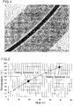
Fig. 2 shows temperatures of the inside of the heating apparatus and a graph indicating relations with the time. -
Fig. 3 is a graph indicating the changes of the internal pressure of the fire detection tube having the barrier layer consisting of various synthetic resins. -
Fig. 4 is a graph indicating the changes of the internal pressure of the fire detection tube having the barrier layer consisting of the EVOH resin having different thickness. -
Fig. 5 is an illustration indicating a setting example of the automatic fire extinguishing device of the direct system. -
Fig. 6 is an illustration indicating a setting example of the automatic fire extinguishing device of the indirect system. - It was achieved to provide a fire detection tube having good fire responsiveness of the activation temperature being lower than 120 degrees Celsius and to provide an automatic fire extinguishing device using this fire detection tube with a simple structure without losing gas barrier capacity.
- The fire detection tubes used for the experiment are the
testing specimen 1 ~ 4. As for thetesting specimen 1 ~ 4 , the inside diameter is 4mm, the outer diameter is 6mm and the full length is 2000mm. Nitrogen gas ( N2 ) is filled within the inside of thetesting specimen 1 ∼ 4, and the both ends of thetesting specimen 1 ∼ 4 are sealed by the thermo compression. The internal pressure of thetesting specimen 1 ∼ 4 is 1.8Mpa. - As indicated in
Fig. 1 , the lamination which is laminated on both sides of thegas barrier layer 18, made of EVOH resin with thebase resin layer 22, made of the PE resin through theadhesive layer 20 is used fortesting specimen adhesive layer 20, polyolefin resin denaturalized by the functional group such as maleic anhydride is used. The thickness of thegas barrier layer 18 is 0.005mm. As for the material of thetesting specimen -
- Name of the Manufacturer: Kato Inc.
- Name of the Product: Silvery Emperor
- Type of the Model: SSE-45K-A
- The rupture temperature and the duration time are examined by the conditions of the
testing specimen 1 ∼ 4 in the heating apparatus being heated by 3 degrees Celsius/min from the temperature of 24 degrees Celsius. The upper limit of the heating temperature is 190 degrees Celsius. - The result of the experiment is indicated on Table 1 and
Figure 2 .[Table 1] Testing Specimen Quantity of Pressurization(Mpa) Operation Temperature(° C) Operation Time 1 1.8 92 18 min. 50 sec. 2 1.8 92 18 min. 50 sec. 3 1.8 179 48 min. 30 sec. 4 1.8 179 48 min. 40 sec. - The rupturing temperature of the fire detection tube of the
testing specimen embodiment 1 is around 90 degrees Celsius whereas the explosion temperature of the fire detection tube of thetesting specimen embodiment 1 is around 180 degrees Celsius. Therefore it is proved that the fire detecting tube of the embodiment can be activated immediately at the temperature of lower than 120 degrees Celsius. - Using various kinds of materials for the gas barrier layer and putting pressure to the inside of the fire detection tube consisting of these gas barrier layer by the nitrogen gas, the relationship between the pressure inside of the fire detection tube and the lapsing time (years) was obtained. As for the fire detecting tube, the length is 10 m, the central diameter of the tube is 5 mm, surface area of the tube is 157079.6 mm2/10m, the inner diameter of the tube is 4 mm and the content volume (inner capacity) is 125663.7 mm3/ 10m. The pressure of the inside of the fire detection tube is 1.8 MPa.
- As for the materials of the gas barrier layer, EVOH resin, PET resin, PAN resin and PVDC resin are used. The thickness of the gas barrier layer consisting of EVOH resin is 0.005 mm. The thickness of the gas barrier layer consisting of PET resin, the gas barrier layer consisting of PAN resin and the gas barrier layer consisting of PVCD resin are all 0.1 mm. For the comparison example a fire detection tube consisting of PA resin (thickness is 1 mm) is also used.
- As for the nitrogen permeability rate,
EVOH resin is 0.017cc· 20 µm / (m2 · day· atm), PET resin is 8cc· 20 µm / (m2 · day· atm), PAN resin is 5cc· 20 µm / (m2· day atm), PVDC resin is 6cc- 20 µm / (m2· day· atm), and PA resin is 12cc· 20 µm / (m2· day· atm). - Trying to obtain a relationship between the pressure of the inside of the fire detection tube and the lapse of years under the conditions above, the result is shown in
Fig. 3 . The result ofFig. 3 shows that the fall of the pressure of the fire detection tube, which is laminated with the gas barrier layer consisting of the EVOH resin, is lower for a long time than the fall of the pressure of the fire detection tube with a gas barrier layer consisting of PET resin, PAN resin or PVDC resin. In comparison with decline of the pressure of the fire detection tube consisting of polyamide resin, the decline of the pressure of the fire detecting tube laminated with the gas barrier layer consisting of the EVOH resin is less for a long time. - After trying to obtain a relationship between the lapse of time (years) and the inner pressure of the gas barrier layer consisting of the EVOH resin, the thickness of the gas barrier layer consisting of the EVOH resin was gradually changed from 0.002 mm, 0.005 mm, 0.02 mm to 0.1 mm, and the result is indicated in
Fig. 4 . - According to the result of
Fig. 4 , it is preferable that the range of the thickness of the gas barrier layer is between 0.005 mm and 0.02 mm, as the fall of the inner pressure is small, if the thickness of the gas barrier layer is between 0.005 mm and 0.02 mm. However, even if the range of the thickness of the gas barrier layer is less than 0.005 mm, it can still be used as the fall of the internal pressure is smaller than that of the fire detection tube consisting of the PA resin, even in a range of thickness of the gas barrier layer between 0.005 and 0.002 mm. - In the above embodiment example of the fire detection tube, the outer diameter is 6 mm, the inner diameter is 4 mm and the thickness of the gas barrier layer is 0.002 ~ 0.1 mm. If the fire detection tube is too thick or the thickness of the gas barrier layer is too big, it is difficult to install it in the small space such as the inside of the engine room of the car or the switchboard. Thus, the inner and outer diameters of the fire detection tube and the thickness of the gas barrier layer should be designed properly based on the above viewpoints.
- In the
above embodiment 1, EVOH resin was used as the material of the gas barrier layer, but the permeance experiment was done by making a fire detection tube using an aluminum film as the gas barrier layer instead of the EVOH resin because the transmissivity of the pressurization gas (nitrogen gas) of the aluminum film is so low that it might be said it is nearly zero in comparison with the EVOH resin. Similar results as the experiment of theembodiment 1 using the fire detection tube are obtained. - The present invention of this automatic fire extinguishing device is applicable to use not only to extinguish a fire caused by a lithium ion battery installed in a car but also to extinguish a fire of a switchboard, a distribution board, an electricity board, a server rack, a dust collector, a NC lathe, a grinder, various machine tools, a storage of inflammables, a chemical experimental device, a fireproof safekeeping, an important documents library, oil storehouse et al.
-
- 10 : PRESSURE RESISTANT CONTAINER
- 12 : CONTAINER VALVE
- 14 : FIRE DETECTION TUBE
- 16 : PRESSURE GAUGE
- 18 : GAS BARRIER LAYER
- 20 : ADHESIVE LAYER
- 22 : BASE RESIN LAYER
Claims (8)
- Automatic fire extinguishing device, characterized in that it includes a pressure resistant container which includes an extinguishant and an pressurization agent inside, an container valve attached to the opening of the pressure resistant container, an fire detection tube connected to the container valve, the fire detection tube equipped with a tubular base layer and a gas barrier layer laminated coaxially with the base resin layer, wherein the base resin layer comprises a thermoplastic resin and the gas barrier layer consists of ethylene-vinyl alcohol copolymer resin (EVOH resin).
- Automatic fire extinguishing device according to Claim 1, characterized by the gas barrier layer being sandwiched by said base resin layers, or the gas barrier layer being laminated on one side of the base resin layer.
- Automatic fire extinguishing device according to Claim 1 or 2 characterized by said gas barrier layer and said base resin layer being laminated by the adhesive layers.
- Automatic fire extinguishing device of any one of Claims 1 to 3, characterized by the thickness of the above gas barrier layer being 0.005 mm ∼ 0.1 mm.
- Fire detection tube of an automatic fire extinguishing device, characterized in that the fire detection tube contains a tubular shaped base resin layer and a gas barrier layer laminated coaxially with the base resin layer, the base resin layer consisting of thermoplastic resin and the gas barrier layer consisting of EVOH resin.
- Fire detection tube according to Claim 5, characterized in that the gas barrier layer is sandwiched by the base resin layers or the gas barrier layer being laminated on one side of the base resin layer.
- Fire detection tube according to Claim 5 or 6, characterized in that the gas barrier layer and the base resin layer are laminated by the adhesive layer.
- Fire detection tube according to any one of Claim 5 - 7, characterized by the thickness of the gas barrier layer being 0.005 mm to 0.1 mm.
Applications Claiming Priority (1)
| Application Number | Priority Date | Filing Date | Title |
|---|---|---|---|
| PCT/JP2014/074209 WO2016038732A1 (en) | 2014-09-12 | 2014-09-12 | Automatic fire-extinguishing device and fire-detecting tube for use in said automatic fire-extinguishing device |
Publications (3)
| Publication Number | Publication Date |
|---|---|
| EP3192570A1 true EP3192570A1 (en) | 2017-07-19 |
| EP3192570A4 EP3192570A4 (en) | 2018-04-11 |
| EP3192570B1 EP3192570B1 (en) | 2023-11-08 |
Family
ID=55453781
Family Applications (1)
| Application Number | Title | Priority Date | Filing Date |
|---|---|---|---|
| EP14878388.9A Active EP3192570B1 (en) | 2014-09-12 | 2014-09-12 | Automatic fire-extinguishing device and fire-detecting tube for use in said automatic fire-extinguishing device |
Country Status (7)
| Country | Link |
|---|---|
| US (1) | US9962568B2 (en) |
| EP (1) | EP3192570B1 (en) |
| JP (1) | JP6362176B2 (en) |
| KR (1) | KR101800520B1 (en) |
| CN (1) | CN105611972B (en) |
| TW (1) | TW201609221A (en) |
| WO (1) | WO2016038732A1 (en) |
Cited By (1)
| Publication number | Priority date | Publication date | Assignee | Title |
|---|---|---|---|---|
| CN109011260A (en) * | 2018-10-22 | 2018-12-18 | 重庆理工大学 | A kind of spy fire tube for new-energy automobile lithium ion battery temperature-sensitive self-starting extinguishing device |
Families Citing this family (15)
| Publication number | Priority date | Publication date | Assignee | Title |
|---|---|---|---|---|
| USD869500S1 (en) * | 2016-04-06 | 2019-12-10 | Inventio Ag | Display screen with icon |
| CN106178373B (en) * | 2016-07-07 | 2017-08-25 | 江苏锡宜消防工程有限公司 | One kind is on fire trace tube formula Automatic spark detection extinguishing device |
| IT201600118870A1 (en) * | 2016-11-24 | 2018-05-24 | Cyber S R L | FIRE-FIGHTING SYSTEM FOR A COMPATIBLE TYPE OF STORAGE AND STORAGE GROUP |
| TWI666848B (en) * | 2018-09-12 | 2019-07-21 | 財團法人工業技術研究院 | Fire control device for power storage system and operating method thereof |
| EP3903017B1 (en) * | 2019-03-12 | 2023-03-22 | Nikola Corporation | Pressurized vessel heat shield and thermal pressure relief system |
| CN111324060B (en) * | 2020-01-15 | 2021-07-06 | 上海船舶电子设备研究所(中国船舶重工集团公司第七二六研究所) | Container valve control method and system suitable for fire alarm control |
| TWI723879B (en) * | 2020-05-19 | 2021-04-01 | 高樹萍 | Fire extinguisher having automatic detection function |
| FR3110447B1 (en) * | 2020-05-20 | 2024-11-22 | Hutchinson | FIRE EXTINGUISHING OR FIRE OUTBREAK LIMITATION |
| CN111632326B (en) * | 2020-06-10 | 2021-08-03 | 湖北航天化学技术研究所 | Thermal runaway detection device and application thereof |
| KR102829857B1 (en) * | 2020-07-20 | 2025-07-04 | 현대자동차주식회사 | Fire extinguishing system for vehicle |
| TWI901799B (en) * | 2020-10-29 | 2025-10-21 | 美商科慕Fc有限責任公司 | Thermal protection of lithium ion batteries and method for terminating thermal runaway |
| CN113202242B (en) * | 2021-03-30 | 2022-07-19 | 浙江上青元电力科技有限公司 | Multi-section fireproof material |
| JP7066099B1 (en) | 2021-09-24 | 2022-05-13 | 増男 山本 | Polypropylene rope burnout detection type automatic fire extinguishing device |
| CN114129932A (en) * | 2021-11-15 | 2022-03-04 | 中国科学技术大学 | Fire detection and suppression device for lithium ion battery energy storage module |
| JP7727083B1 (en) * | 2024-12-23 | 2025-08-20 | エア・ウォーター防災株式会社 | Fire extinguishing equipment management system |
Family Cites Families (27)
| Publication number | Priority date | Publication date | Assignee | Title |
|---|---|---|---|---|
| GB1357010A (en) * | 1971-05-03 | 1974-06-19 | Chubb Fire Security Ltd | Fire-extinguishing apparatus |
| FR2310141A1 (en) * | 1975-05-06 | 1976-12-03 | Petroles Cie Francaise | FIRE EXTINGUISHING UNIT FOR THE PROTECTION OF LARGE VOLUMES AND LARGE SURFACES |
| JPH0814719B2 (en) | 1987-12-01 | 1996-02-14 | 東洋インキ製造株式会社 | Electrostatic toner |
| GB8926849D0 (en) * | 1989-11-28 | 1990-01-17 | Melton David L | Fire extinguisher |
| JP3170412B2 (en) | 1994-04-27 | 2001-05-28 | 株式会社クボタ | Sputtering target member for forming non-magnetic underlayer of metal thin film type magnetic recording medium |
| US5909776A (en) * | 1997-04-16 | 1999-06-08 | Powsus Inc. | Fire extinguishers |
| US6161624A (en) * | 1999-11-29 | 2000-12-19 | The United States Of America As Represented By The Secretary Of The Air Force | Linear fire extinguisher |
| JP2002018999A (en) * | 2000-07-06 | 2002-01-22 | Toyoda Gosei Co Ltd | Resin laminate |
| JP2002282381A (en) | 2001-03-27 | 2002-10-02 | Hatsuta Seisakusho Co Ltd | Hose for sensing piping of simultaneous release valve |
| JP2004176908A (en) * | 2002-10-03 | 2004-06-24 | Bridgestone Corp | Low gas-permeability hose |
| JP2004169851A (en) * | 2002-11-21 | 2004-06-17 | Sanoh Industrial Co Ltd | Multi-layer tube |
| JP2004196926A (en) * | 2002-12-18 | 2004-07-15 | Toray Ind Inc | Pressure-resistant container and high-pressure body sealed container made of thermoplastic resin |
| JP4509033B2 (en) * | 2004-01-27 | 2010-07-21 | 宇部興産株式会社 | Laminated tube |
| JP4746906B2 (en) * | 2005-04-11 | 2011-08-10 | ヤマトプロテック株式会社 | Automatic fire extinguisher |
| TWM298441U (en) * | 2006-04-14 | 2006-10-01 | Cheng-Sz Peng | Improved structure of dry type fire-extinguisher |
| CN101680670B (en) * | 2007-04-16 | 2012-10-03 | 东洋克斯株式会社 | Cooling/heating panel |
| JP5224171B2 (en) * | 2008-01-28 | 2013-07-03 | 株式会社トヨックス | Ceiling air conditioning panel |
| GB2474271B (en) * | 2009-10-08 | 2014-04-02 | Kidde Tech Inc | Fire suppression system |
| US8752640B1 (en) * | 2010-08-18 | 2014-06-17 | ULD Fire Systems, LLC | Method for detecting and suppressing fire in a container |
| JP5725500B2 (en) * | 2011-02-01 | 2015-05-27 | 株式会社ヱビス科学研究所 | Fire extinguishing liquid and simple fire extinguishing tool filled with the same |
| US8851197B2 (en) * | 2011-04-28 | 2014-10-07 | Pacific Scientific Energetic Materials Company | Self contained fire extinguisher system including a linear temperature sensor |
| KR101263166B1 (en) * | 2011-05-18 | 2013-05-10 | 정종백 | Small genades typed fire extinguisher having a function of beep |
| JP3170412U (en) | 2011-07-04 | 2011-09-15 | エア・ウォーター防災株式会社 | Fire extinguisher |
| KR101295042B1 (en) * | 2012-01-31 | 2013-08-09 | 주식회사 건국이엔아이 | Fire extinguisher with fire detecition tube |
| EP2722077B1 (en) * | 2012-10-17 | 2019-08-14 | Fogmaker International AB | Fire detection system |
| WO2014069022A1 (en) * | 2012-11-02 | 2014-05-08 | 株式会社ニチボウ | Automatic fire extinguisher |
| US10118059B2 (en) * | 2013-09-27 | 2018-11-06 | Nichibou Co., Ltd. | Automatic fire extinguishing equipment |
-
2014
- 2014-09-12 CN CN201480005733.2A patent/CN105611972B/en active Active
- 2014-09-12 EP EP14878388.9A patent/EP3192570B1/en active Active
- 2014-09-12 WO PCT/JP2014/074209 patent/WO2016038732A1/en not_active Ceased
- 2014-09-12 JP JP2015546359A patent/JP6362176B2/en active Active
- 2014-09-12 KR KR1020157014888A patent/KR101800520B1/en active Active
- 2014-09-12 US US14/647,934 patent/US9962568B2/en active Active
- 2014-09-30 TW TW103134048A patent/TW201609221A/en unknown
Cited By (1)
| Publication number | Priority date | Publication date | Assignee | Title |
|---|---|---|---|---|
| CN109011260A (en) * | 2018-10-22 | 2018-12-18 | 重庆理工大学 | A kind of spy fire tube for new-energy automobile lithium ion battery temperature-sensitive self-starting extinguishing device |
Also Published As
| Publication number | Publication date |
|---|---|
| CN105611972A (en) | 2016-05-25 |
| US20160074686A1 (en) | 2016-03-17 |
| TWI559958B (en) | 2016-12-01 |
| JP6362176B2 (en) | 2018-07-25 |
| US9962568B2 (en) | 2018-05-08 |
| KR20160047421A (en) | 2016-05-02 |
| TW201609221A (en) | 2016-03-16 |
| EP3192570A4 (en) | 2018-04-11 |
| WO2016038732A1 (en) | 2016-03-17 |
| KR101800520B1 (en) | 2017-11-22 |
| CN105611972B (en) | 2019-11-08 |
| JPWO2016038732A1 (en) | 2017-06-22 |
| EP3192570B1 (en) | 2023-11-08 |
Similar Documents
| Publication | Publication Date | Title |
|---|---|---|
| EP3192570B1 (en) | Automatic fire-extinguishing device and fire-detecting tube for use in said automatic fire-extinguishing device | |
| JP6456818B2 (en) | Fire extinguisher | |
| US7253002B2 (en) | Fluid storage and dispensing vessels having colorimetrically verifiable leak-tightness, and method of making same | |
| CA2805241C (en) | Methods and apparatus for passive non-electrical dual stage fire suppression | |
| US8733382B2 (en) | Thermally activated safety valve for pressure vessels | |
| US12398818B2 (en) | Thermal pressure relief device (TPRD), gas pressure tank and gas pressure tank system comprising TPRD and method for thermal excess pressure protection | |
| US20190046822A1 (en) | Automatic fire extinguisher | |
| RU2595990C2 (en) | Methods and device for multistage fire extinguishing system | |
| CN109499027A (en) | A kind of perfluor hexanone battery compartment fire extinguishing system | |
| CN105510140A (en) | Pressure bursting test system and method for low-temperature deep-cooling pressure vessels and pipelines | |
| EP4309745A1 (en) | Layered product for extinguishing fire, production method for layered product for extinguishing fire, and electronic member | |
| CN110420427A (en) | Perfluor hexanone automatic fire extinguishing system and its working method | |
| EP2311756B1 (en) | Leakage self-help container for stocking hazardous chemical products | |
| WO2018149772A1 (en) | Composite pressure vessel for hydrogen storage | |
| CN109011260A (en) | A kind of spy fire tube for new-energy automobile lithium ion battery temperature-sensitive self-starting extinguishing device | |
| JP2009516142A (en) | Device and method for protecting a cooling tank and tank having such a device | |
| CN116020069A (en) | A power battery pack fire extinguishing and explosion suppression system | |
| CN117446369A (en) | A special container for battery transportation | |
| CN110585627A (en) | External pressure storage fire extinguishing system and fire extinguishing method for automobile lithium battery |
Legal Events
| Date | Code | Title | Description |
|---|---|---|---|
| STAA | Information on the status of an ep patent application or granted ep patent |
Free format text: STATUS: THE INTERNATIONAL PUBLICATION HAS BEEN MADE |
|
| PUAI | Public reference made under article 153(3) epc to a published international application that has entered the european phase |
Free format text: ORIGINAL CODE: 0009012 |
|
| STAA | Information on the status of an ep patent application or granted ep patent |
Free format text: STATUS: REQUEST FOR EXAMINATION WAS MADE |
|
| 17P | Request for examination filed |
Effective date: 20170412 |
|
| AK | Designated contracting states |
Kind code of ref document: A1 Designated state(s): AL AT BE BG CH CY CZ DE DK EE ES FI FR GB GR HR HU IE IS IT LI LT LU LV MC MK MT NL NO PL PT RO RS SE SI SK SM TR |
|
| AX | Request for extension of the european patent |
Extension state: BA ME |
|
| DAX | Request for extension of the european patent (deleted) | ||
| A4 | Supplementary search report drawn up and despatched |
Effective date: 20180312 |
|
| RIC1 | Information provided on ipc code assigned before grant |
Ipc: A62C 35/10 20060101AFI20180306BHEP Ipc: F16L 11/12 20060101ALI20180306BHEP |
|
| STAA | Information on the status of an ep patent application or granted ep patent |
Free format text: STATUS: EXAMINATION IS IN PROGRESS |
|
| 17Q | First examination report despatched |
Effective date: 20200120 |
|
| 19U | Interruption of proceedings before grant |
Effective date: 20200210 |
|
| 19W | Proceedings resumed before grant after interruption of proceedings |
Effective date: 20200901 |
|
| GRAP | Despatch of communication of intention to grant a patent |
Free format text: ORIGINAL CODE: EPIDOSNIGR1 |
|
| STAA | Information on the status of an ep patent application or granted ep patent |
Free format text: STATUS: GRANT OF PATENT IS INTENDED |
|
| INTG | Intention to grant announced |
Effective date: 20230627 |
|
| GRAS | Grant fee paid |
Free format text: ORIGINAL CODE: EPIDOSNIGR3 |
|
| GRAA | (expected) grant |
Free format text: ORIGINAL CODE: 0009210 |
|
| STAA | Information on the status of an ep patent application or granted ep patent |
Free format text: STATUS: THE PATENT HAS BEEN GRANTED |
|
| AK | Designated contracting states |
Kind code of ref document: B1 Designated state(s): AL AT BE BG CH CY CZ DE DK EE ES FI FR GB GR HR HU IE IS IT LI LT LU LV MC MK MT NL NO PL PT RO RS SE SI SK SM TR |
|
| REG | Reference to a national code |
Ref country code: GB Ref legal event code: FG4D |
|
| REG | Reference to a national code |
Ref country code: CH Ref legal event code: EP |
|
| REG | Reference to a national code |
Ref country code: DE Ref legal event code: R096 Ref document number: 602014088832 Country of ref document: DE |
|
| REG | Reference to a national code |
Ref country code: IE Ref legal event code: FG4D |
|
| REG | Reference to a national code |
Ref country code: SE Ref legal event code: TRGR |
|
| REG | Reference to a national code |
Ref country code: LT Ref legal event code: MG9D |
|
| REG | Reference to a national code |
Ref country code: NL Ref legal event code: MP Effective date: 20231108 |
|
| PG25 | Lapsed in a contracting state [announced via postgrant information from national office to epo] |
Ref country code: GR Free format text: LAPSE BECAUSE OF FAILURE TO SUBMIT A TRANSLATION OF THE DESCRIPTION OR TO PAY THE FEE WITHIN THE PRESCRIBED TIME-LIMIT Effective date: 20240209 |
|
| PG25 | Lapsed in a contracting state [announced via postgrant information from national office to epo] |
Ref country code: IS Free format text: LAPSE BECAUSE OF FAILURE TO SUBMIT A TRANSLATION OF THE DESCRIPTION OR TO PAY THE FEE WITHIN THE PRESCRIBED TIME-LIMIT Effective date: 20240308 |
|
| PG25 | Lapsed in a contracting state [announced via postgrant information from national office to epo] |
Ref country code: LT Free format text: LAPSE BECAUSE OF FAILURE TO SUBMIT A TRANSLATION OF THE DESCRIPTION OR TO PAY THE FEE WITHIN THE PRESCRIBED TIME-LIMIT Effective date: 20231108 |
|
| REG | Reference to a national code |
Ref country code: AT Ref legal event code: MK05 Ref document number: 1629105 Country of ref document: AT Kind code of ref document: T Effective date: 20231108 |
|
| PG25 | Lapsed in a contracting state [announced via postgrant information from national office to epo] |
Ref country code: NL Free format text: LAPSE BECAUSE OF FAILURE TO SUBMIT A TRANSLATION OF THE DESCRIPTION OR TO PAY THE FEE WITHIN THE PRESCRIBED TIME-LIMIT Effective date: 20231108 |
|
| PG25 | Lapsed in a contracting state [announced via postgrant information from national office to epo] |
Ref country code: AT Free format text: LAPSE BECAUSE OF FAILURE TO SUBMIT A TRANSLATION OF THE DESCRIPTION OR TO PAY THE FEE WITHIN THE PRESCRIBED TIME-LIMIT Effective date: 20231108 |
|
| PG25 | Lapsed in a contracting state [announced via postgrant information from national office to epo] |
Ref country code: ES Free format text: LAPSE BECAUSE OF FAILURE TO SUBMIT A TRANSLATION OF THE DESCRIPTION OR TO PAY THE FEE WITHIN THE PRESCRIBED TIME-LIMIT Effective date: 20231108 |
|
| PG25 | Lapsed in a contracting state [announced via postgrant information from national office to epo] |
Ref country code: NL Free format text: LAPSE BECAUSE OF FAILURE TO SUBMIT A TRANSLATION OF THE DESCRIPTION OR TO PAY THE FEE WITHIN THE PRESCRIBED TIME-LIMIT Effective date: 20231108 Ref country code: LT Free format text: LAPSE BECAUSE OF FAILURE TO SUBMIT A TRANSLATION OF THE DESCRIPTION OR TO PAY THE FEE WITHIN THE PRESCRIBED TIME-LIMIT Effective date: 20231108 Ref country code: IS Free format text: LAPSE BECAUSE OF FAILURE TO SUBMIT A TRANSLATION OF THE DESCRIPTION OR TO PAY THE FEE WITHIN THE PRESCRIBED TIME-LIMIT Effective date: 20240308 Ref country code: GR Free format text: LAPSE BECAUSE OF FAILURE TO SUBMIT A TRANSLATION OF THE DESCRIPTION OR TO PAY THE FEE WITHIN THE PRESCRIBED TIME-LIMIT Effective date: 20240209 Ref country code: ES Free format text: LAPSE BECAUSE OF FAILURE TO SUBMIT A TRANSLATION OF THE DESCRIPTION OR TO PAY THE FEE WITHIN THE PRESCRIBED TIME-LIMIT Effective date: 20231108 Ref country code: BG Free format text: LAPSE BECAUSE OF FAILURE TO SUBMIT A TRANSLATION OF THE DESCRIPTION OR TO PAY THE FEE WITHIN THE PRESCRIBED TIME-LIMIT Effective date: 20240208 Ref country code: AT Free format text: LAPSE BECAUSE OF FAILURE TO SUBMIT A TRANSLATION OF THE DESCRIPTION OR TO PAY THE FEE WITHIN THE PRESCRIBED TIME-LIMIT Effective date: 20231108 Ref country code: PT Free format text: LAPSE BECAUSE OF FAILURE TO SUBMIT A TRANSLATION OF THE DESCRIPTION OR TO PAY THE FEE WITHIN THE PRESCRIBED TIME-LIMIT Effective date: 20240308 |
|
| PG25 | Lapsed in a contracting state [announced via postgrant information from national office to epo] |
Ref country code: RS Free format text: LAPSE BECAUSE OF FAILURE TO SUBMIT A TRANSLATION OF THE DESCRIPTION OR TO PAY THE FEE WITHIN THE PRESCRIBED TIME-LIMIT Effective date: 20231108 Ref country code: PL Free format text: LAPSE BECAUSE OF FAILURE TO SUBMIT A TRANSLATION OF THE DESCRIPTION OR TO PAY THE FEE WITHIN THE PRESCRIBED TIME-LIMIT Effective date: 20231108 Ref country code: NO Free format text: LAPSE BECAUSE OF FAILURE TO SUBMIT A TRANSLATION OF THE DESCRIPTION OR TO PAY THE FEE WITHIN THE PRESCRIBED TIME-LIMIT Effective date: 20240208 Ref country code: LV Free format text: LAPSE BECAUSE OF FAILURE TO SUBMIT A TRANSLATION OF THE DESCRIPTION OR TO PAY THE FEE WITHIN THE PRESCRIBED TIME-LIMIT Effective date: 20231108 Ref country code: HR Free format text: LAPSE BECAUSE OF FAILURE TO SUBMIT A TRANSLATION OF THE DESCRIPTION OR TO PAY THE FEE WITHIN THE PRESCRIBED TIME-LIMIT Effective date: 20231108 |
|
| PG25 | Lapsed in a contracting state [announced via postgrant information from national office to epo] |
Ref country code: DK Free format text: LAPSE BECAUSE OF FAILURE TO SUBMIT A TRANSLATION OF THE DESCRIPTION OR TO PAY THE FEE WITHIN THE PRESCRIBED TIME-LIMIT Effective date: 20231108 |
|
| PG25 | Lapsed in a contracting state [announced via postgrant information from national office to epo] |
Ref country code: CZ Free format text: LAPSE BECAUSE OF FAILURE TO SUBMIT A TRANSLATION OF THE DESCRIPTION OR TO PAY THE FEE WITHIN THE PRESCRIBED TIME-LIMIT Effective date: 20231108 |
|
| PG25 | Lapsed in a contracting state [announced via postgrant information from national office to epo] |
Ref country code: SK Free format text: LAPSE BECAUSE OF FAILURE TO SUBMIT A TRANSLATION OF THE DESCRIPTION OR TO PAY THE FEE WITHIN THE PRESCRIBED TIME-LIMIT Effective date: 20231108 |
|
| PG25 | Lapsed in a contracting state [announced via postgrant information from national office to epo] |
Ref country code: SM Free format text: LAPSE BECAUSE OF FAILURE TO SUBMIT A TRANSLATION OF THE DESCRIPTION OR TO PAY THE FEE WITHIN THE PRESCRIBED TIME-LIMIT Effective date: 20231108 Ref country code: SK Free format text: LAPSE BECAUSE OF FAILURE TO SUBMIT A TRANSLATION OF THE DESCRIPTION OR TO PAY THE FEE WITHIN THE PRESCRIBED TIME-LIMIT Effective date: 20231108 Ref country code: RO Free format text: LAPSE BECAUSE OF FAILURE TO SUBMIT A TRANSLATION OF THE DESCRIPTION OR TO PAY THE FEE WITHIN THE PRESCRIBED TIME-LIMIT Effective date: 20231108 Ref country code: EE Free format text: LAPSE BECAUSE OF FAILURE TO SUBMIT A TRANSLATION OF THE DESCRIPTION OR TO PAY THE FEE WITHIN THE PRESCRIBED TIME-LIMIT Effective date: 20231108 Ref country code: DK Free format text: LAPSE BECAUSE OF FAILURE TO SUBMIT A TRANSLATION OF THE DESCRIPTION OR TO PAY THE FEE WITHIN THE PRESCRIBED TIME-LIMIT Effective date: 20231108 Ref country code: CZ Free format text: LAPSE BECAUSE OF FAILURE TO SUBMIT A TRANSLATION OF THE DESCRIPTION OR TO PAY THE FEE WITHIN THE PRESCRIBED TIME-LIMIT Effective date: 20231108 |
|
| REG | Reference to a national code |
Ref country code: DE Ref legal event code: R097 Ref document number: 602014088832 Country of ref document: DE |
|
| PLBE | No opposition filed within time limit |
Free format text: ORIGINAL CODE: 0009261 |
|
| STAA | Information on the status of an ep patent application or granted ep patent |
Free format text: STATUS: NO OPPOSITION FILED WITHIN TIME LIMIT |
|
| 26N | No opposition filed |
Effective date: 20240809 |
|
| PG25 | Lapsed in a contracting state [announced via postgrant information from national office to epo] |
Ref country code: SI Free format text: LAPSE BECAUSE OF FAILURE TO SUBMIT A TRANSLATION OF THE DESCRIPTION OR TO PAY THE FEE WITHIN THE PRESCRIBED TIME-LIMIT Effective date: 20231108 |
|
| PG25 | Lapsed in a contracting state [announced via postgrant information from national office to epo] |
Ref country code: SI Free format text: LAPSE BECAUSE OF FAILURE TO SUBMIT A TRANSLATION OF THE DESCRIPTION OR TO PAY THE FEE WITHIN THE PRESCRIBED TIME-LIMIT Effective date: 20231108 |
|
| PG25 | Lapsed in a contracting state [announced via postgrant information from national office to epo] |
Ref country code: MC Free format text: LAPSE BECAUSE OF FAILURE TO SUBMIT A TRANSLATION OF THE DESCRIPTION OR TO PAY THE FEE WITHIN THE PRESCRIBED TIME-LIMIT Effective date: 20231108 |
|
| REG | Reference to a national code |
Ref country code: CH Ref legal event code: PL |
|
| PG25 | Lapsed in a contracting state [announced via postgrant information from national office to epo] |
Ref country code: LU Free format text: LAPSE BECAUSE OF NON-PAYMENT OF DUE FEES Effective date: 20240912 |
|
| REG | Reference to a national code |
Ref country code: BE Ref legal event code: MM Effective date: 20240930 |
|
| PG25 | Lapsed in a contracting state [announced via postgrant information from national office to epo] |
Ref country code: BE Free format text: LAPSE BECAUSE OF NON-PAYMENT OF DUE FEES Effective date: 20240930 |
|
| PG25 | Lapsed in a contracting state [announced via postgrant information from national office to epo] |
Ref country code: CH Free format text: LAPSE BECAUSE OF NON-PAYMENT OF DUE FEES Effective date: 20240930 |
|
| PG25 | Lapsed in a contracting state [announced via postgrant information from national office to epo] |
Ref country code: IE Free format text: LAPSE BECAUSE OF NON-PAYMENT OF DUE FEES Effective date: 20240912 |
|
| PG25 | Lapsed in a contracting state [announced via postgrant information from national office to epo] |
Ref country code: FI Free format text: LAPSE BECAUSE OF FAILURE TO SUBMIT A TRANSLATION OF THE DESCRIPTION OR TO PAY THE FEE WITHIN THE PRESCRIBED TIME-LIMIT Effective date: 20231108 |
|
| PGFP | Annual fee paid to national office [announced via postgrant information from national office to epo] |
Ref country code: DE Payment date: 20250919 Year of fee payment: 12 |
|
| PGFP | Annual fee paid to national office [announced via postgrant information from national office to epo] |
Ref country code: TR Payment date: 20250908 Year of fee payment: 12 Ref country code: IT Payment date: 20250923 Year of fee payment: 12 |
|
| PGFP | Annual fee paid to national office [announced via postgrant information from national office to epo] |
Ref country code: GB Payment date: 20250919 Year of fee payment: 12 |
|
| PGFP | Annual fee paid to national office [announced via postgrant information from national office to epo] |
Ref country code: FR Payment date: 20250922 Year of fee payment: 12 |
|
| PGFP | Annual fee paid to national office [announced via postgrant information from national office to epo] |
Ref country code: SE Payment date: 20250918 Year of fee payment: 12 |
|
| PG25 | Lapsed in a contracting state [announced via postgrant information from national office to epo] |
Ref country code: CY Free format text: LAPSE BECAUSE OF FAILURE TO SUBMIT A TRANSLATION OF THE DESCRIPTION OR TO PAY THE FEE WITHIN THE PRESCRIBED TIME-LIMIT; INVALID AB INITIO Effective date: 20140912 |
|
| PG25 | Lapsed in a contracting state [announced via postgrant information from national office to epo] |
Ref country code: HU Free format text: LAPSE BECAUSE OF FAILURE TO SUBMIT A TRANSLATION OF THE DESCRIPTION OR TO PAY THE FEE WITHIN THE PRESCRIBED TIME-LIMIT; INVALID AB INITIO Effective date: 20140912 |