EP3192439A1 - Bioinformation measuring device - Google Patents
Bioinformation measuring device Download PDFInfo
- Publication number
- EP3192439A1 EP3192439A1 EP15840904.5A EP15840904A EP3192439A1 EP 3192439 A1 EP3192439 A1 EP 3192439A1 EP 15840904 A EP15840904 A EP 15840904A EP 3192439 A1 EP3192439 A1 EP 3192439A1
- Authority
- EP
- European Patent Office
- Prior art keywords
- biological information
- measurement apparatus
- biological
- information measurement
- insertion portion
- Prior art date
- Legal status (The legal status is an assumption and is not a legal conclusion. Google has not performed a legal analysis and makes no representation as to the accuracy of the status listed.)
- Granted
Links
Images




Classifications
-
- A—HUMAN NECESSITIES
- A61—MEDICAL OR VETERINARY SCIENCE; HYGIENE
- A61B—DIAGNOSIS; SURGERY; IDENTIFICATION
- A61B5/00—Measuring for diagnostic purposes; Identification of persons
- A61B5/02—Detecting, measuring or recording for evaluating the cardiovascular system, e.g. pulse, heart rate, blood pressure or blood flow
- A61B5/024—Measuring pulse rate or heart rate
-
- A—HUMAN NECESSITIES
- A61—MEDICAL OR VETERINARY SCIENCE; HYGIENE
- A61B—DIAGNOSIS; SURGERY; IDENTIFICATION
- A61B5/00—Measuring for diagnostic purposes; Identification of persons
- A61B5/02—Detecting, measuring or recording for evaluating the cardiovascular system, e.g. pulse, heart rate, blood pressure or blood flow
- A61B5/024—Measuring pulse rate or heart rate
- A61B5/02416—Measuring pulse rate or heart rate using photoplethysmograph signals, e.g. generated by infrared radiation
- A61B5/02427—Details of sensor
-
- A—HUMAN NECESSITIES
- A61—MEDICAL OR VETERINARY SCIENCE; HYGIENE
- A61B—DIAGNOSIS; SURGERY; IDENTIFICATION
- A61B5/00—Measuring for diagnostic purposes; Identification of persons
- A61B5/02—Detecting, measuring or recording for evaluating the cardiovascular system, e.g. pulse, heart rate, blood pressure or blood flow
-
- A—HUMAN NECESSITIES
- A61—MEDICAL OR VETERINARY SCIENCE; HYGIENE
- A61B—DIAGNOSIS; SURGERY; IDENTIFICATION
- A61B5/00—Measuring for diagnostic purposes; Identification of persons
- A61B5/02—Detecting, measuring or recording for evaluating the cardiovascular system, e.g. pulse, heart rate, blood pressure or blood flow
- A61B5/024—Measuring pulse rate or heart rate
- A61B5/02416—Measuring pulse rate or heart rate using photoplethysmograph signals, e.g. generated by infrared radiation
-
- A—HUMAN NECESSITIES
- A61—MEDICAL OR VETERINARY SCIENCE; HYGIENE
- A61B—DIAGNOSIS; SURGERY; IDENTIFICATION
- A61B5/00—Measuring for diagnostic purposes; Identification of persons
- A61B5/02—Detecting, measuring or recording for evaluating the cardiovascular system, e.g. pulse, heart rate, blood pressure or blood flow
- A61B5/024—Measuring pulse rate or heart rate
- A61B5/02438—Measuring pulse rate or heart rate with portable devices, e.g. worn by the patient
-
- A—HUMAN NECESSITIES
- A61—MEDICAL OR VETERINARY SCIENCE; HYGIENE
- A61B—DIAGNOSIS; SURGERY; IDENTIFICATION
- A61B5/00—Measuring for diagnostic purposes; Identification of persons
- A61B5/68—Arrangements of detecting, measuring or recording means, e.g. sensors, in relation to patient
- A61B5/6801—Arrangements of detecting, measuring or recording means, e.g. sensors, in relation to patient specially adapted to be attached to or worn on the body surface
- A61B5/6813—Specially adapted to be attached to a specific body part
- A61B5/6814—Head
- A61B5/6815—Ear
- A61B5/6817—Ear canal
-
- A—HUMAN NECESSITIES
- A61—MEDICAL OR VETERINARY SCIENCE; HYGIENE
- A61B—DIAGNOSIS; SURGERY; IDENTIFICATION
- A61B5/00—Measuring for diagnostic purposes; Identification of persons
- A61B5/68—Arrangements of detecting, measuring or recording means, e.g. sensors, in relation to patient
- A61B5/6801—Arrangements of detecting, measuring or recording means, e.g. sensors, in relation to patient specially adapted to be attached to or worn on the body surface
- A61B5/683—Means for maintaining contact with the body
-
- H—ELECTRICITY
- H04—ELECTRIC COMMUNICATION TECHNIQUE
- H04R—LOUDSPEAKERS, MICROPHONES, GRAMOPHONE PICK-UPS OR LIKE ACOUSTIC ELECTROMECHANICAL TRANSDUCERS; ELECTRIC HEARING AIDS; PUBLIC ADDRESS SYSTEMS
- H04R25/00—Electric hearing aids
- H04R25/30—Monitoring or testing of hearing aids, e.g. functioning, settings, battery power
-
- A—HUMAN NECESSITIES
- A61—MEDICAL OR VETERINARY SCIENCE; HYGIENE
- A61B—DIAGNOSIS; SURGERY; IDENTIFICATION
- A61B2562/00—Details of sensors; Constructional details of sensor housings or probes; Accessories for sensors
- A61B2562/18—Shielding or protection of sensors from environmental influences, e.g. protection from mechanical damage
- A61B2562/185—Optical shielding, e.g. baffles
-
- H—ELECTRICITY
- H04—ELECTRIC COMMUNICATION TECHNIQUE
- H04R—LOUDSPEAKERS, MICROPHONES, GRAMOPHONE PICK-UPS OR LIKE ACOUSTIC ELECTROMECHANICAL TRANSDUCERS; ELECTRIC HEARING AIDS; PUBLIC ADDRESS SYSTEMS
- H04R1/00—Details of transducers, loudspeakers or microphones
- H04R1/10—Earpieces; Attachments therefor ; Earphones; Monophonic headphones
- H04R1/1016—Earpieces of the intra-aural type
Definitions
- This disclosure relates to a biological information measurement apparatus.
- Biological information measurement apparatuses that measure biological information of a user, such as pulse, have been proposed. Biological information is measured by a variety of methods using a biological information measurement apparatus.
- a biological information measurement apparatus For example, US20080220535 A1 (PTL 1) and US20120283578 A1 (PTL 2) disclose a pulse measurement apparatus in which a compact pulse wave sensor is mounted in an earphone. By the user inserting the earphone in the ear, the pulse can be measured using the pulse wave sensor.
- the position of the earphone might shift due to body movement or the like. If the position of the biological information measurement apparatus changes, noise is included in the biological information measured using the sensor, making it difficult to measure biological information accurately.
- a biological information measurement apparatus includes: a biological sensor and an insertion portion; such that the biological sensor is disposed at a position opposite a concha when the insertion portion is inserted in an external ear canal.
- the measurement accuracy of biological information can be improved.
- a biological information measurement apparatus 100 is provided with an earpiece 110 that includes a biological sensor 111 and an insertion portion 112.
- the earpiece 110 is worn in a user's ear.
- FIG. 1 is a functional block diagram of a section of the biological information measurement apparatus 100 according to Embodiment 1.
- the biological information measurement apparatus 100 according to this embodiment is provided with the earpiece 110, a controller 120, a memory 160, a communication interface 140, and a notification interface 150.
- the biological information measurement apparatus 100 measures biological information using the biological sensor 111 provided in the earpiece 110 after the user has inserted the insertion portion 112 into the external ear canal.
- the biological information may be any biological information that can be measured using the biological sensor 111 provided in the earpiece 110.
- the biological information measurement apparatus 100 is described below as measuring the user's pulse.
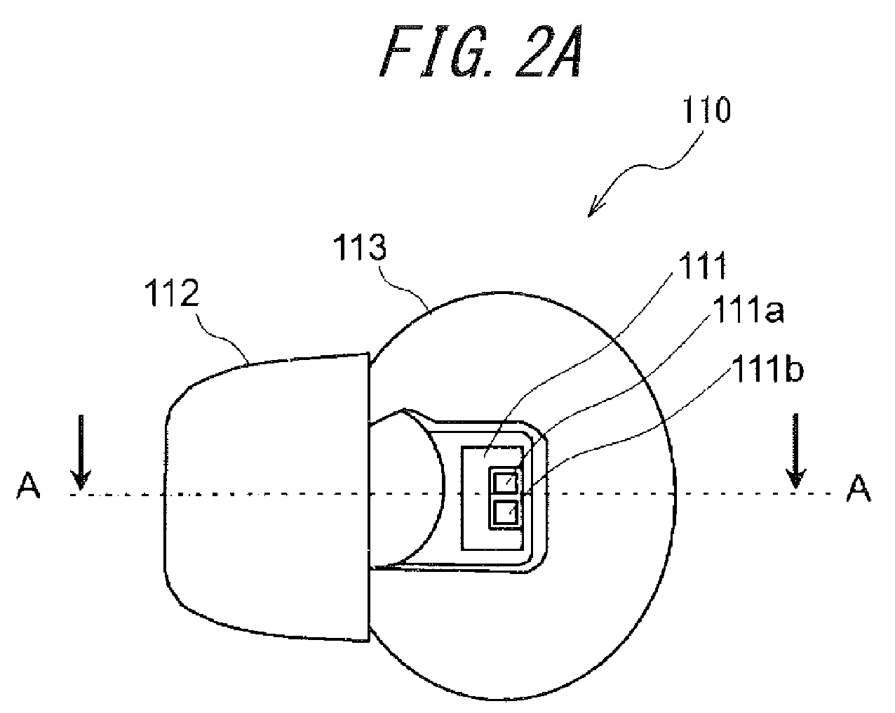
- FIG. 2A schematically illustrates the structure of the earpiece 110 according to Embodiment 1.
- FIG. 2B is a schematic cross-sectional drawing when observing the A-A cross-section illustrated in FIG. 2A in the direction of the arrows.
- the earpiece 110 is inserted in the user's external ear canal towards the left.
- the earpiece 110 is provided with the biological sensor 111, the insertion portion 112, a pad 113, and a housing 114.
- the biological sensor 111, insertion portion 112, and pad 113 are disposed inside the housing 114. Once the insertion portion 112 is inserted in the user's external ear canal, the biological sensor 111 is disposed so as to oppose the user's concha.
- the biological sensor 111 is a pulse wave sensor and acquires pulse wave data from the user (living organism) as biological measurement output.
- the biological sensor 111 is provided with a optical emitter 111a and a optical detector 111b.
- a light emitting element such as a Light Emitting Diode (LED) is provided in the optical emitter 111a.
- a light detecting element such as a Phototransistor (PT) or a Photodiode (PD) is provided in the optical detector 111b.
- the biological sensor 111 measures pulse wave data by irradiating measurement light from the light emitting element onto the test site of the user's external ear canal and detecting reflected light from the test site with the light detecting element. In the case of measuring such light, the biological sensor 111 does not necessarily have to contact the site to be measured.
- the optical emitter 111 and optical detector 111b of the biological sensor 111 are arranged in parallel inside the housing, with a light-blocking wall therebetween. The light-blocking wall is disposed so that light emitted from the optical emitter 111a is not directly detected by the optical detector 111b.
- a protective, translucent panel is arranged in the biological sensor 111, and the inside of the biological sensor 111 is sealed off by the translucent panel.
- the biological sensor 111 includes a driver (not illustrated).
- the driver drives the light emitting element and the light detecting element based on a measurement signal generated by the controller 120.
- the light emitting element and the light detecting element emit and detect light by being driven by the driver.
- Driving of the driver is, for example, controlled by the controller 120.
- the optical emitter 111a uses a blue (wavelength: 400 nm to 430 nm) or green (wavelength: 500 nm to 550 nm) LED or laser. Blue or green light of the aforementioned wavelength is easily absorbed by hemoglobin. The amount of absorbed light increases if the blood flow rate is high, and the output of the optical detector 111b weakens. A red (wavelength: 630 nm to 650 nm) LED or laser may also be used. In this case, since hemoglobin reflects red light, the amount of reflected light increases if the blood flow rate is high, and the output of the optical detector 111b grows stronger. PDs corresponding to the various wavelengths are used in the optical detector 111b.
- the insertion portion 112 is disposed on the side of the housing 114 inserted into the external ear canal. When inserted into the external ear canal, the insertion portion 112 abuts the external ear canal. The user inserts the insertion portion 112 into the external ear canal so that the biological sensor 111 opposes the concha. When inserted into the external ear canal, the insertion portion 112 deforms in accordance with the shape of the external ear canal to attach firmly to the external ear canal. The earpiece 110 is held at a predetermined position of the ear by the insertion portion 112 attaching firmly to the external ear canal.
- the insertion portion 112 is formed from a material that has elasticity at room temperature and may, for example, be made of resin with a Shore hardness of approximately 30 to 60.
- the insertion portion 112 may, for example, be formed by silicone rubber, flexible polyurethane resin, or the like.
- the pad 113 engages with the opposite end of the housing 114 from the side that is inserted into the external ear canal.
- the pad 113 may be formed from a material having elasticity at room temperature, such as silicone rubber or flexible polyurethane resin.
- the pad 113 contacts the back side of the tragus and the back side portion of the antitragus, and together with the insertion portion 112, holds the earpiece 110 at a predetermined position of the ear.
- the space surrounded by the concha, the housing 114, and the biological sensor 111 is in a state (structure) in which light from the exterior cannot penetrate easily due to the outer peripheral portion of the pad 113.
- a portion of the pad 113 may be disposed at the periphery of the biological sensor 111.
- the pad 113 may be raised towards the concha from the surface of the biological sensor 111.
- the pad 113 is raised towards the concha from the surface of the biological sensor 111 by a thickness of t mm.
- the thickness t mm may, for example, be approximately 0.5 mm to 3 mm.
- the pad 113 contacts the periphery of the concha around the biological sensor 111.
- the pad 113 prevents external light from being detected by the optical detector 111b when the biological sensor 111 acquires biological information.
- the pad 113 may, for example, be formed from light-blocking material such as black silicone rubber.
- the pad 113 may have a hollow structure so as to easily deform to match the size of the user's cavum conchae (the portion surrounded by the concha, the back side of the tragus, and the back side of the antitragus).
- the pad 113 prevents the earpiece 110 from deviating from a predetermined position even when the user exercises intensely. Furthermore, the pad 113 prevents light from entering into the optical detector 111b from the outside. Accordingly, a biological information acquisition apparatus according to this disclosure can acquire biological information with a higher degree of accuracy.
- the insertion portion 112 is engaged with the housing 114 at the side of the housing 114 inserted into the external ear canal.
- the biological sensor 111 is disposed in the housing 114 on a surface opposite the concha when the earpiece 110 is worn in the ear.
- the pad 113 is engaged with the housing 114 at the opposite end from the side of the housing 114 inserted into the external ear canal.
- a vent 115 (air hole) is provided in the housing 114.
- the vent 115 is an air hole that opens to the outside of the ear from the external ear canal when the earpiece 110 is worn.
- the vent 115 may be formed as a hole in the housing 114 or be formed by recessing a portion of the housing 114. By the vent 115 being provided in the housing 114, the user can hear external sounds while measuring biological information, thereby improving user safety.
- the housing 114 may, for example, be formed from polycarbonate resin, amine-based resin, or the like. In this embodiment, the housing 114, insertion portion 112, and pad 113 engage to constitute the earpiece 110, but this disclosure is not limited to this configuration.
- the housing 114, insertion portion 112, and pad 113 may be formed integrally using the same material.
- various wires are laid for power signals from the biological sensor 111 and to supply power to the biological sensor 111.
- the controller 120 is a processor that controls overall operations of the biological information measurement apparatus 100.
- the controller 120 measures the pulse as biological information based on pulse wave data acquired by the biological sensor 111.
- the controller 120 judges whether the pulse wave data, which is biological measurement output, are within an allowable range that can be used to measure biological information. When judging that the pulse wave data are not within the allowable range, the controller 120 provides notification of an error with the notification interface 150. Conversely, when judging that the pulse wave data are within the allowable range, the controller 120 provides notification with the notification interface 150 of the start of measurement.
- the memory 160 may, for example, be configured with a semiconductor memory, a magnetic memory, or the like.
- the memory 160 stores a variety of information, programs for causing the biological information measurement apparatus 100 to operate, and the like.
- the memory 160 for example stores information (a threshold) on the allowable range that serves as the standard for judging whether the pulse wave data acquired by the biological sensor 111 can be used to measure biological information.
- the communication interface 140 is connected to and communicates with a mobile phone via a wired connection or a wireless connection such as Bluetooth ® (Bluetooth is a registered trademark in Japan, other countries, or both).
- the biological information measurement apparatus 100 for example transmits the biological information measured by the controller 120 to a mobile phone 200 via the communication interface 140.
- the notification interface 150 notifies the user based on control by the controller 120, for example with a visual method using an image, characters, light emission, or the like; an auditory method using audio or the like; or a combination of these methods.
- the notification interface 150 may, for example, provide notification by displaying images or characters on a display device constituted by a liquid crystal display, organic EL display, inorganic EL display, or the like.
- the notification interface 150 may, for example, provide notification by causing an LED or other such light emitting element, separate from the biological sensor 111, to emit light.
- Notification by the notification interface 150 is not limited to a visual or auditory method. Any method recognizable by the user may be adopted.
- the controller 120 may provide notification by, for example, displaying images or characters on a display 260 of the mobile phone 200 connected via the communication interface 140. In this case, the biological information measurement apparatus 100 need not be provided with the notification interface 150.
- the controller 120, memory 160, notification interface 150, and communication interface 140 may be provided in the earpiece 110.
- the controller 120, memory 160, and notification interface 150 may be provided in the mobile phone 200, since it suffices for the biological information measurement apparatus 100 to be provided with at least the insertion portion 112 and the biological sensor 111.
- the mobile phone 200 may, for example, be a smartphone and is connected to the biological information measurement apparatus 100.
- the mobile phone 200 includes a mobile phone controller 220, a communication interface 240, the display 260, and an input interface 270.
- the mobile phone controller 220 is a processor that controls overall operations of the mobile phone 200.
- the mobile phone controller 220 may, for example, display the biological information measured by the biological information measurement apparatus 100 on the display 260.
- the communication interface 240 is connected to and communicates with the biological information measurement apparatus 100 by a wired or wireless connection.
- the mobile phone 200 for example receives the biological information measured by the biological information measurement apparatus 100 via the communication interface 240.
- the display 260 is a display device such as a liquid crystal display, an organic EL display, an inorganic EL display, or the like.
- the display 260 for example displays the biological information measured by the biological information measurement apparatus 100. The user can learn his own biological information by checking the display of the display 260.
- the input interface 270 accepts operation input from the user and may be configured, for example, using operation buttons (operation keys).
- the input interface 270 may be configured by a touchscreen, an input region that accepts operation input from the user may be displayed on a portion of the display 260, and touch operation input by the user to this input region may be accepted.
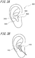
- FIG. 3A schematically illustrates the structure of an ear.
- FIG. 3B illustrates the earpiece 110 of FIGS. 2A and 2B as worn in the ear.
- the biological information measurement apparatus 100 measures biological information with the insertion portion 112 in the earpiece 110 being inserted in an external ear canal 340 so that the biological sensor 111 opposes a concha 310.
- the optical emitter 111a emits light towards the concha.
- the emitted light is reflected or scattered by the concha and detected by the optical detector 111b.
- the intensity of the reflected light varies in synchronization with the pulse. By observing this variation in the intensity of reflected light as a pulse wave, the pulse can be acquired.
- the portion of the concha that is measured is wider than, for example, the inner wall of the external ear canal. Accordingly, the degree of freedom for arranging the biological sensor 111 increases. For example, light can be emitted over a wider area by separating the optical emitter 111a from the concha rather than attaching the optical emitter 111a firmly to the concha. Also, the concha is flatter than, for example, the inner wall of the external ear canal. Accordingly, the direction of reflected light is constant, allowing the optical detector 111b to detect intense light stably. In this way, biological information over a wide area can be detected as intense light, thereby improving the measurement accuracy of biological information. Also, it is difficult for external light to penetrate into the space enclosed by the concha and the biological sensor 111, thereby improving the measurement accuracy of biological information.
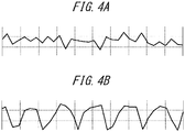
- FIG. 4A illustrates an example of pulse wave data acquired by a known biological information measurement apparatus.
- FIG. 4B illustrates an example of pulse wave data acquired by the biological sensor 111 according to Embodiment 1.
- the horizontal axis represents time, and the intensity of detected light is plotted along the vertical axis.
- a biological sensor provided with a optical emitter and a optical detector is abutted against the back side of the antitragus and acquires pulse wave data.
- the pulse wave data were measured after the subject performed a predetermined exercise for 5 minutes while wearing the biological information measurement apparatus.
- a comparison of FIG. 4A and FIG. 4B shows that in the pulse wave data in FIG.
- the period of the peaks is unstable, and the amplitude is small and inconsistent.
- the pulse wave data of FIG. 4B the period of the peaks is stable, and the amplitude is large and consistent.
- the pulse wave data acquired by the biological sensor 111 according to Embodiment 1 clearly has better measurement accuracy than the pulse wave data acquired by a known biological information measurement apparatus. Confirmation of the state in which the known biological information measurement apparatus was worn after measurement revealed that the biological sensor which was abutted against the back side of the antitragus had become misaligned, allowing external light to enter the optical detector. By contrast, the biological information measurement apparatus 100 according to Embodiment 1 was worn in a stable state.
- FIG. 5 compares the pulse measurement results for the biological information measurement apparatus 100 according to Embodiment 1 and a known biological information measurement apparatus. Pulse measurements were taken for 32 men and 18 women, for a total of 50 people. The known biological information measurement apparatus used a known method 1 to take measurements at a fingertip and a known method 2 to take measurements at the back side of the antitragus. The pulse was measured with the subject at rest. So that the subject state would not change, measurements were taken successively with the three methods for each subject.
- the pulse acquisition rate is the probability that the pulse could be measured.
- the pulse acquisition rate was 100% for the biological information measurement apparatus 100 according to Embodiment 1.
- the pulse acquisition rate was 96%, since an error occurred because of the pulse not being detectable due to poor circulation at the fingertip.
- the pulse acquisition rate was 92%, since an error occurred because of the biological information measurement apparatus not being able to abut against the back side of the antitragus due to not matching the size of the ear.
- the average pulse is the average of the pulse acquired for 50 people.
- the known method 2 yielded a higher average pulse than the other methods, suggesting a problem with measurement accuracy.
- a widely known cohort study yielded the results of an average pulse of 62 ⁇ 9.5 for 11,463 people.
- the average pulse measured by the biological information measurement apparatus 100 of this disclosure was 70.2. Since this value is within the range of the average pulse indicated by the cohort study, the value measured by the biological information measurement apparatus 100 according to Embodiment 1 can be deemed reliable.
- FIG. 6 schematically illustrates the cross-sectional shape of the biological information measurement apparatus according to Embodiment 2. The differences from the biological information measurement apparatus 100 according to Embodiment 1 are described below, with a detailed description of points that are the same being omitted.
- the biological information measurement apparatus includes a speaker 136.
- the speaker 136 is formed by a diaphragm 137 and a driver 138.
- the speaker 136 is held in a housing 134b, and the housing 134b engages with a housing 134a.
- a vent 135a in the housing 134a and a vent 135b in the housing 134b are connected.
- the vent opens to the outside of the ear from the external ear canal. By the vent being provided, the user can hear external sounds while listening to music with the speaker, thereby improving user safety.
- the sound produced by the speaker 136 is transmitted in the direction of insertion of an insertion portion 132 into the external ear canal, i.e. into the user's ear.
- the driver 138 vibrates the diaphragm 137 based on a sound signal of sound generated by the mobile phone 200.
- the diaphragm 137 vibrates based on driving by the driver 138 and reproduces sound.
- Driving of the driver 138 is, for example, controlled by the controller 120.
- the direction of vibration of the diaphragm 137 is indicated in FIG. 6 by arrows.
- the speaker 136 is disposed so that the direction of insertion of the insertion portion 132 into the external ear canal and the direction of vibration of the diaphragm 137 are approximately parallel.
- the angle between the approximately parallel direction of vibration of the diaphragm 137 and direction of insertion of the insertion portion 132 is in a range of 0° to 10°.
- reflection of sound decreases.
- vibration of sound is more easily transmitted to the eardrum.
- the speaker upon wearing the earpiece 130 in the ear, the speaker is disposed outside of the ear. Therefore, a large speaker 136 can be selected without impairing the fit of the earpiece.
- the speaker of this disclosure is not limited to being arranged in this way and may instead by disposed at the opposite end of the housing 134a, where the biological sensor 131 is disposed.
- the biological information measurement apparatus has been described as measuring the pulse, but the measured biological information is not limited to this case.
- the measured biological information may, for example, be the rate of blood flow.
- an infrared light (wavelength: 1.31 micrometers or 1.55 micrometers) laser may be used, and the relative rate of blood flow may be detected from the change in wavelength occurring due to the Doppler shift.
- the measured biological information may, for example, be body temperature instead. Body temperature is, for example, detected by thermal radiation (infrared radiation) outward from the concha. Body temperature may, for example, also be detected using a thermistor.
- the pad 113 When measuring rate of blood flow or body temperature as the biological information, the pad 113 functions as a light-blocking member while also functioning as a heat-blocking member. By including the pad 113, the biological information measurement apparatus is not easily affected by external temperature, allowing stable measurement of biological information.
- the measured biological information may, for example, be blood pressure or the oxygen content of the blood.
- the biological information measurement apparatus is not limited to measuring one type of measured biological information and may measure a plurality of types of biological information by combining a plurality of sensors.
Landscapes
- Health & Medical Sciences (AREA)
- Life Sciences & Earth Sciences (AREA)
- Cardiology (AREA)
- General Health & Medical Sciences (AREA)
- Engineering & Computer Science (AREA)
- Physics & Mathematics (AREA)
- Surgery (AREA)
- Molecular Biology (AREA)
- Veterinary Medicine (AREA)
- Public Health (AREA)
- Animal Behavior & Ethology (AREA)
- Biophysics (AREA)
- Pathology (AREA)
- Medical Informatics (AREA)
- Heart & Thoracic Surgery (AREA)
- Biomedical Technology (AREA)
- Physiology (AREA)
- Otolaryngology (AREA)
- Signal Processing (AREA)
- Acoustics & Sound (AREA)
- Neurosurgery (AREA)
- Measuring Pulse, Heart Rate, Blood Pressure Or Blood Flow (AREA)
Abstract
Description
- This application claims priority to and the benefit of Japanese Patent Application No.
2014-182378 filed September 8, 2014 - This disclosure relates to a biological information measurement apparatus.
- Biological information measurement apparatuses that measure biological information of a user, such as pulse, have been proposed. Biological information is measured by a variety of methods using a biological information measurement apparatus. For example,
US20080220535 A1 (PTL 1) andUS20120283578 A1 (PTL 2) disclose a pulse measurement apparatus in which a compact pulse wave sensor is mounted in an earphone. By the user inserting the earphone in the ear, the pulse can be measured using the pulse wave sensor. -
- PTL 1:
US20080220535 A1 - PTL 2:
US20120283578 A1 - In a known pulse measurement apparatus, however, the position of the earphone might shift due to body movement or the like. If the position of the biological information measurement apparatus changes, noise is included in the biological information measured using the sensor, making it difficult to measure biological information accurately.
- Therefore, it would be helpful to provide a biological information measurement apparatus that can improve the measurement accuracy of biological information.
- A biological information measurement apparatus according to this disclosure includes: a biological sensor and an insertion portion; such that the biological sensor is disposed at a position opposite a concha when the insertion portion is inserted in an external ear canal.
- According to the biological information measurement apparatus with the aforementioned configuration according to this disclosure, the measurement accuracy of biological information can be improved.
- In the accompanying drawings:
-
FIG. 1 is a functional block diagram of a section of the biological information measurement apparatus according toEmbodiment 1; -
FIG. 2A schematically illustrates the structure of the biological information measurement apparatus according toEmbodiment 1; -
FIG. 2B schematically illustrates the cross-sectional shape of the biological information measurement apparatus according toEmbodiment 1; -
FIG. 3A schematically illustrates the structure of an ear; -
FIG. 3B illustrates the biological information measurement apparatus inFIGS. 2A and 2B as worn in an ear; -
FIG. 4A illustrates an example of pulse wave data acquired by a known biological information measurement apparatus; -
FIG. 4B illustrates an example of pulse wave data acquired by the biological sensor inFIG. 1 ; -
FIG. 5 compares the pulse measurement results for the biological information measurement apparatus according toEmbodiment 1 and a known apparatus; and -
FIG. 6 schematically illustrates the cross-sectional shape of the biological information measurement apparatus according to Embodiment 2. - The following describes embodiments of the disclosed apparatus.
- In general terms, a biological
information measurement apparatus 100 according toEmbodiment 1 is provided with anearpiece 110 that includes abiological sensor 111 and aninsertion portion 112. Theearpiece 110 is worn in a user's ear. -
FIG. 1 is a functional block diagram of a section of the biologicalinformation measurement apparatus 100 according toEmbodiment 1. The biologicalinformation measurement apparatus 100 according to this embodiment is provided with theearpiece 110, acontroller 120, amemory 160, acommunication interface 140, and anotification interface 150. The biologicalinformation measurement apparatus 100 measures biological information using thebiological sensor 111 provided in theearpiece 110 after the user has inserted theinsertion portion 112 into the external ear canal. - The biological information may be any biological information that can be measured using the
biological sensor 111 provided in theearpiece 110. In this embodiment, as one example, the biologicalinformation measurement apparatus 100 is described below as measuring the user's pulse. -
FIG. 2A schematically illustrates the structure of theearpiece 110 according toEmbodiment 1.FIG. 2B is a schematic cross-sectional drawing when observing the A-A cross-section illustrated inFIG. 2A in the direction of the arrows. InFIG. 2A and FIG. 2B , theearpiece 110 is inserted in the user's external ear canal towards the left. Theearpiece 110 is provided with thebiological sensor 111, theinsertion portion 112, apad 113, and ahousing 114. Thebiological sensor 111,insertion portion 112, andpad 113 are disposed inside thehousing 114. Once theinsertion portion 112 is inserted in the user's external ear canal, thebiological sensor 111 is disposed so as to oppose the user's concha. - The
biological sensor 111 is a pulse wave sensor and acquires pulse wave data from the user (living organism) as biological measurement output. Thebiological sensor 111 is provided with aoptical emitter 111a and aoptical detector 111b. In thebiological sensor 111 according to this disclosure, for example a light emitting element such as a Light Emitting Diode (LED) is provided in theoptical emitter 111a. In thebiological sensor 111 according to this disclosure, for example a light detecting element such as a Phototransistor (PT) or a Photodiode (PD) is provided in theoptical detector 111b. Thebiological sensor 111 measures pulse wave data by irradiating measurement light from the light emitting element onto the test site of the user's external ear canal and detecting reflected light from the test site with the light detecting element. In the case of measuring such light, thebiological sensor 111 does not necessarily have to contact the site to be measured. Theoptical emitter 111 andoptical detector 111b of thebiological sensor 111 are arranged in parallel inside the housing, with a light-blocking wall therebetween. The light-blocking wall is disposed so that light emitted from theoptical emitter 111a is not directly detected by theoptical detector 111b. A protective, translucent panel is arranged in thebiological sensor 111, and the inside of thebiological sensor 111 is sealed off by the translucent panel. - The
biological sensor 111 includes a driver (not illustrated). The driver drives the light emitting element and the light detecting element based on a measurement signal generated by thecontroller 120. The light emitting element and the light detecting element emit and detect light by being driven by the driver. Driving of the driver is, for example, controlled by thecontroller 120. - In the case of measuring pulse, the
optical emitter 111a uses a blue (wavelength: 400 nm to 430 nm) or green (wavelength: 500 nm to 550 nm) LED or laser. Blue or green light of the aforementioned wavelength is easily absorbed by hemoglobin. The amount of absorbed light increases if the blood flow rate is high, and the output of theoptical detector 111b weakens. A red (wavelength: 630 nm to 650 nm) LED or laser may also be used. In this case, since hemoglobin reflects red light, the amount of reflected light increases if the blood flow rate is high, and the output of theoptical detector 111b grows stronger. PDs corresponding to the various wavelengths are used in theoptical detector 111b. - The
insertion portion 112 is disposed on the side of thehousing 114 inserted into the external ear canal. When inserted into the external ear canal, theinsertion portion 112 abuts the external ear canal. The user inserts theinsertion portion 112 into the external ear canal so that thebiological sensor 111 opposes the concha. When inserted into the external ear canal, theinsertion portion 112 deforms in accordance with the shape of the external ear canal to attach firmly to the external ear canal. Theearpiece 110 is held at a predetermined position of the ear by theinsertion portion 112 attaching firmly to the external ear canal. Theinsertion portion 112 is formed from a material that has elasticity at room temperature and may, for example, be made of resin with a Shore hardness of approximately 30 to 60. Theinsertion portion 112 may, for example, be formed by silicone rubber, flexible polyurethane resin, or the like. - The
pad 113 engages with the opposite end of thehousing 114 from the side that is inserted into the external ear canal. In order to make it easier for the user to wear theearpiece 110, thepad 113 may be formed from a material having elasticity at room temperature, such as silicone rubber or flexible polyurethane resin. Thepad 113 contacts the back side of the tragus and the back side portion of the antitragus, and together with theinsertion portion 112, holds theearpiece 110 at a predetermined position of the ear. On the other hand, the space surrounded by the concha, thehousing 114, and thebiological sensor 111 is in a state (structure) in which light from the exterior cannot penetrate easily due to the outer peripheral portion of thepad 113. A portion of thepad 113 may be disposed at the periphery of thebiological sensor 111. Thepad 113 may be raised towards the concha from the surface of thebiological sensor 111. For example, as illustrated inFIG. 2B , thepad 113 is raised towards the concha from the surface of thebiological sensor 111 by a thickness of t mm. The thickness t mm may, for example, be approximately 0.5 mm to 3 mm. Thepad 113 contacts the periphery of the concha around thebiological sensor 111. Thepad 113 prevents external light from being detected by theoptical detector 111b when thebiological sensor 111 acquires biological information. In order to further increase the light blocking effect, thepad 113 may, for example, be formed from light-blocking material such as black silicone rubber. Thepad 113 may have a hollow structure so as to easily deform to match the size of the user's cavum conchae (the portion surrounded by the concha, the back side of the tragus, and the back side of the antitragus). Thepad 113 prevents theearpiece 110 from deviating from a predetermined position even when the user exercises intensely. Furthermore, thepad 113 prevents light from entering into theoptical detector 111b from the outside. Accordingly, a biological information acquisition apparatus according to this disclosure can acquire biological information with a higher degree of accuracy. - When the
earpiece 110 is worn in the ear, theinsertion portion 112 is engaged with thehousing 114 at the side of thehousing 114 inserted into the external ear canal. Thebiological sensor 111 is disposed in thehousing 114 on a surface opposite the concha when theearpiece 110 is worn in the ear. When theearpiece 110 is worn in the ear, thepad 113 is engaged with thehousing 114 at the opposite end from the side of thehousing 114 inserted into the external ear canal. A vent 115 (air hole) is provided in thehousing 114. Thevent 115 is an air hole that opens to the outside of the ear from the external ear canal when theearpiece 110 is worn. Thevent 115 may be formed as a hole in thehousing 114 or be formed by recessing a portion of thehousing 114. By thevent 115 being provided in thehousing 114, the user can hear external sounds while measuring biological information, thereby improving user safety. Thehousing 114 may, for example, be formed from polycarbonate resin, amine-based resin, or the like. In this embodiment, thehousing 114,insertion portion 112, and pad 113 engage to constitute theearpiece 110, but this disclosure is not limited to this configuration. Thehousing 114,insertion portion 112, and pad 113 may be formed integrally using the same material. - In the interior and exterior of the
earpiece 110, various wires (not illustrated) are laid for power signals from thebiological sensor 111 and to supply power to thebiological sensor 111. - Referring again to
FIG. 1 , thecontroller 120 is a processor that controls overall operations of the biologicalinformation measurement apparatus 100. When the user measures biological information, thecontroller 120 measures the pulse as biological information based on pulse wave data acquired by thebiological sensor 111. - For example, the
controller 120 judges whether the pulse wave data, which is biological measurement output, are within an allowable range that can be used to measure biological information. When judging that the pulse wave data are not within the allowable range, thecontroller 120 provides notification of an error with thenotification interface 150. Conversely, when judging that the pulse wave data are within the allowable range, thecontroller 120 provides notification with thenotification interface 150 of the start of measurement. - The
memory 160 may, for example, be configured with a semiconductor memory, a magnetic memory, or the like. Thememory 160 stores a variety of information, programs for causing the biologicalinformation measurement apparatus 100 to operate, and the like. Thememory 160 for example stores information (a threshold) on the allowable range that serves as the standard for judging whether the pulse wave data acquired by thebiological sensor 111 can be used to measure biological information. - The
communication interface 140 is connected to and communicates with a mobile phone via a wired connection or a wireless connection such as Bluetooth® (Bluetooth is a registered trademark in Japan, other countries, or both). The biologicalinformation measurement apparatus 100 for example transmits the biological information measured by thecontroller 120 to amobile phone 200 via thecommunication interface 140. - The
notification interface 150 notifies the user based on control by thecontroller 120, for example with a visual method using an image, characters, light emission, or the like; an auditory method using audio or the like; or a combination of these methods. In the case of providing notification with a visual method, thenotification interface 150 may, for example, provide notification by displaying images or characters on a display device constituted by a liquid crystal display, organic EL display, inorganic EL display, or the like. Thenotification interface 150 may, for example, provide notification by causing an LED or other such light emitting element, separate from thebiological sensor 111, to emit light. Notification by thenotification interface 150 is not limited to a visual or auditory method. Any method recognizable by the user may be adopted. - The
controller 120 may provide notification by, for example, displaying images or characters on adisplay 260 of themobile phone 200 connected via thecommunication interface 140. In this case, the biologicalinformation measurement apparatus 100 need not be provided with thenotification interface 150. - The
controller 120,memory 160,notification interface 150, andcommunication interface 140 may be provided in theearpiece 110. Alternatively, thecontroller 120,memory 160, andnotification interface 150 may be provided in themobile phone 200, since it suffices for the biologicalinformation measurement apparatus 100 to be provided with at least theinsertion portion 112 and thebiological sensor 111. - The
mobile phone 200 may, for example, be a smartphone and is connected to the biologicalinformation measurement apparatus 100. Themobile phone 200 includes amobile phone controller 220, acommunication interface 240, thedisplay 260, and aninput interface 270. - The
mobile phone controller 220 is a processor that controls overall operations of themobile phone 200. Themobile phone controller 220 may, for example, display the biological information measured by the biologicalinformation measurement apparatus 100 on thedisplay 260. - The
communication interface 240 is connected to and communicates with the biologicalinformation measurement apparatus 100 by a wired or wireless connection. Themobile phone 200 for example receives the biological information measured by the biologicalinformation measurement apparatus 100 via thecommunication interface 240. - The
display 260 is a display device such as a liquid crystal display, an organic EL display, an inorganic EL display, or the like. Thedisplay 260 for example displays the biological information measured by the biologicalinformation measurement apparatus 100. The user can learn his own biological information by checking the display of thedisplay 260. - The
input interface 270 accepts operation input from the user and may be configured, for example, using operation buttons (operation keys). Theinput interface 270 may be configured by a touchscreen, an input region that accepts operation input from the user may be displayed on a portion of thedisplay 260, and touch operation input by the user to this input region may be accepted. -
FIG. 3A schematically illustrates the structure of an ear.FIG. 3B illustrates theearpiece 110 ofFIGS. 2A and 2B as worn in the ear. The biologicalinformation measurement apparatus 100 according to this disclosure measures biological information with theinsertion portion 112 in theearpiece 110 being inserted in anexternal ear canal 340 so that thebiological sensor 111 opposes aconcha 310. Theoptical emitter 111a emits light towards the concha. The emitted light is reflected or scattered by the concha and detected by theoptical detector 111b. The intensity of the reflected light varies in synchronization with the pulse. By observing this variation in the intensity of reflected light as a pulse wave, the pulse can be acquired. The portion of the concha that is measured is wider than, for example, the inner wall of the external ear canal. Accordingly, the degree of freedom for arranging thebiological sensor 111 increases. For example, light can be emitted over a wider area by separating theoptical emitter 111a from the concha rather than attaching theoptical emitter 111a firmly to the concha. Also, the concha is flatter than, for example, the inner wall of the external ear canal. Accordingly, the direction of reflected light is constant, allowing theoptical detector 111b to detect intense light stably. In this way, biological information over a wide area can be detected as intense light, thereby improving the measurement accuracy of biological information. Also, it is difficult for external light to penetrate into the space enclosed by the concha and thebiological sensor 111, thereby improving the measurement accuracy of biological information. -
FIG. 4A illustrates an example of pulse wave data acquired by a known biological information measurement apparatus.FIG. 4B illustrates an example of pulse wave data acquired by thebiological sensor 111 according toEmbodiment 1. In these figures of pulse wave data, the horizontal axis represents time, and the intensity of detected light is plotted along the vertical axis. In a known biological information measurement apparatus, a biological sensor provided with a optical emitter and a optical detector is abutted against the back side of the antitragus and acquires pulse wave data. The pulse wave data were measured after the subject performed a predetermined exercise for 5 minutes while wearing the biological information measurement apparatus. A comparison ofFIG. 4A and FIG. 4B shows that in the pulse wave data inFIG. 4A , the period of the peaks is unstable, and the amplitude is small and inconsistent. By contrast, in the pulse wave data ofFIG. 4B , the period of the peaks is stable, and the amplitude is large and consistent. The pulse wave data acquired by thebiological sensor 111 according toEmbodiment 1 clearly has better measurement accuracy than the pulse wave data acquired by a known biological information measurement apparatus. Confirmation of the state in which the known biological information measurement apparatus was worn after measurement revealed that the biological sensor which was abutted against the back side of the antitragus had become misaligned, allowing external light to enter the optical detector. By contrast, the biologicalinformation measurement apparatus 100 according toEmbodiment 1 was worn in a stable state. -
FIG. 5 compares the pulse measurement results for the biologicalinformation measurement apparatus 100 according toEmbodiment 1 and a known biological information measurement apparatus. Pulse measurements were taken for 32 men and 18 women, for a total of 50 people. The known biological information measurement apparatus used a knownmethod 1 to take measurements at a fingertip and a known method 2 to take measurements at the back side of the antitragus. The pulse was measured with the subject at rest. So that the subject state would not change, measurements were taken successively with the three methods for each subject. - The pulse acquisition rate is the probability that the pulse could be measured. The pulse acquisition rate was 100% for the biological
information measurement apparatus 100 according toEmbodiment 1. With the knownmethod 1, the pulse acquisition rate was 96%, since an error occurred because of the pulse not being detectable due to poor circulation at the fingertip. With the known method 2, the pulse acquisition rate was 92%, since an error occurred because of the biological information measurement apparatus not being able to abut against the back side of the antitragus due to not matching the size of the ear. - The average pulse is the average of the pulse acquired for 50 people. The known method 2 yielded a higher average pulse than the other methods, suggesting a problem with measurement accuracy. A widely known cohort study yielded the results of an average pulse of 62 ± 9.5 for 11,463 people. The average pulse measured by the biological
information measurement apparatus 100 of this disclosure was 70.2. Since this value is within the range of the average pulse indicated by the cohort study, the value measured by the biologicalinformation measurement apparatus 100 according toEmbodiment 1 can be deemed reliable. -
FIG. 6 schematically illustrates the cross-sectional shape of the biological information measurement apparatus according to Embodiment 2. The differences from the biologicalinformation measurement apparatus 100 according toEmbodiment 1 are described below, with a detailed description of points that are the same being omitted. - The biological information measurement apparatus according to Embodiment 2 includes a
speaker 136. Thespeaker 136 is formed by adiaphragm 137 and adriver 138. Thespeaker 136 is held in ahousing 134b, and thehousing 134b engages with ahousing 134a. Avent 135a in thehousing 134a and avent 135b in thehousing 134b are connected. With anearpiece 130 worn in the ear, the vent opens to the outside of the ear from the external ear canal. By the vent being provided, the user can hear external sounds while listening to music with the speaker, thereby improving user safety. - The sound produced by the
speaker 136 is transmitted in the direction of insertion of aninsertion portion 132 into the external ear canal, i.e. into the user's ear. Thedriver 138 vibrates thediaphragm 137 based on a sound signal of sound generated by themobile phone 200. Thediaphragm 137 vibrates based on driving by thedriver 138 and reproduces sound. Driving of thedriver 138 is, for example, controlled by thecontroller 120. - The direction of vibration of the
diaphragm 137 is indicated inFIG. 6 by arrows. Thespeaker 136 is disposed so that the direction of insertion of theinsertion portion 132 into the external ear canal and the direction of vibration of thediaphragm 137 are approximately parallel. The angle between the approximately parallel direction of vibration of thediaphragm 137 and direction of insertion of theinsertion portion 132 is in a range of 0° to 10°. With this arrangement, reflection of sound decreases. Furthermore, vibration of sound is more easily transmitted to the eardrum. Also, upon wearing theearpiece 130 in the ear, the speaker is disposed outside of the ear. Therefore, alarge speaker 136 can be selected without impairing the fit of the earpiece. - The speaker of this disclosure is not limited to being arranged in this way and may instead by disposed at the opposite end of the
housing 134a, where thebiological sensor 131 is disposed. - In the above embodiment, the biological information measurement apparatus has been described as measuring the pulse, but the measured biological information is not limited to this case. The measured biological information may, for example, be the rate of blood flow. When measuring the rate of blood flow, for example an infrared light (wavelength: 1.31 micrometers or 1.55 micrometers) laser may be used, and the relative rate of blood flow may be detected from the change in wavelength occurring due to the Doppler shift. The measured biological information may, for example, be body temperature instead. Body temperature is, for example, detected by thermal radiation (infrared radiation) outward from the concha. Body temperature may, for example, also be detected using a thermistor. When measuring rate of blood flow or body temperature as the biological information, the
pad 113 functions as a light-blocking member while also functioning as a heat-blocking member. By including thepad 113, the biological information measurement apparatus is not easily affected by external temperature, allowing stable measurement of biological information. - The measured biological information may, for example, be blood pressure or the oxygen content of the blood. The biological information measurement apparatus is not limited to measuring one type of measured biological information and may measure a plurality of types of biological information by combining a plurality of sensors.
- Although exemplary embodiments have been described with reference to the accompanying drawings, it is to be noted that various changes and modifications will be apparent to those skilled in the art based on this disclosure. Therefore, such changes and modifications are to be understood as included within the scope of this disclosure. For example, the functions and the like included in the various units and members may be reordered in any logically consistent way. Furthermore, units and members may be combined into one or divided.
-
- 100
- Biological information measurement apparatus
- 110, 130
- Earpiece
- 111, 131
- Biological sensor
- 111a
- Optical emitter
- 111b
- Optical detector
- 112, 132
- Insertion portion
- 113, 133
- Pad
- 114, 134a, 134b
- Housing
- 115, 135a, 135b
- Vent
- 136
- Speaker
- 137
- Diaphragm
- 138
- Driver
- 120
- Controller
- 140
- Communication interface
- 150
- Notification interface
- 160
- Memory
- 200
- Mobile phone
- 220
- Mobile phone controller
- 260
- Display
- 270
- Input interface
- 300
- Ear
- 310
- Concha
- 320
- Tragus
- 330
- Antitragus
- 340
- External ear canal
Claims (7)
- A biological information measurement apparatus comprising:a biological sensor and an insertion portion;wherein the biological sensor is disposed at a position opposite a concha when the insertion portion is inserted in an external ear canal.
- The biological information measurement apparatus of claim 1, further comprising a vent leading from the external ear canal to an exterior when the insertion portion is inserted in the external ear canal.
- The biological information measurement apparatus of claim 2, further comprising:a housing configured to hold the biological sensor and the insertion portion;wherein the vent leading from the external ear canal to the exterior when the insertion portion is inserted in the external ear canal is provided in the housing.
- The biological information measurement apparatus of claim 1,
wherein the biological sensor comprises a optical emitter configured to emit light and a optical detector configured to detect light;
wherein the optical emitter emits light towards the concha, and the optical detector detects light returning from the concha. - The biological information measurement apparatus of claim 4, further comprising a light-blocking portion configured to prevent light other than the light returning from the concha from being detected by the optical detector.
- The biological information measurement apparatus of claim 1, further comprising:a pad surrounding the biological sensor;wherein when the insertion portion is inserted in the external ear canal, the pad is raised towards the concha from a surface where the biological sensor is provided.
- The biological information measurement apparatus of claim 1, further comprising:a speaker configured to generate sound by vibrating a diaphragm;wherein a direction of vibration of the diaphragm is substantially parallel to a direction of insertion of the insertion portion.
Applications Claiming Priority (2)
| Application Number | Priority Date | Filing Date | Title |
|---|---|---|---|
| JP2014182378A JP6254501B2 (en) | 2014-09-08 | 2014-09-08 | Biological information measuring device |
| PCT/JP2015/004570 WO2016038887A1 (en) | 2014-09-08 | 2015-09-08 | Bioinformation measuring device |
Publications (3)
| Publication Number | Publication Date |
|---|---|
| EP3192439A1 true EP3192439A1 (en) | 2017-07-19 |
| EP3192439A4 EP3192439A4 (en) | 2018-02-07 |
| EP3192439B1 EP3192439B1 (en) | 2024-12-18 |
Family
ID=55458657
Family Applications (1)
| Application Number | Title | Priority Date | Filing Date |
|---|---|---|---|
| EP15840904.5A Active EP3192439B1 (en) | 2014-09-08 | 2015-09-08 | Bioinformation measuring device |
Country Status (4)
| Country | Link |
|---|---|
| US (1) | US10646125B2 (en) |
| EP (1) | EP3192439B1 (en) |
| JP (1) | JP6254501B2 (en) |
| WO (1) | WO2016038887A1 (en) |
Cited By (1)
| Publication number | Priority date | Publication date | Assignee | Title |
|---|---|---|---|---|
| WO2022132271A1 (en) * | 2020-12-15 | 2022-06-23 | Starkey Laboratories, Inc. | Physiologic sensing platform for cooperative use with an ear-wearable electronic device |
Families Citing this family (11)
| Publication number | Priority date | Publication date | Assignee | Title |
|---|---|---|---|---|
| JP6659498B2 (en) | 2016-08-30 | 2020-03-04 | 京セラ株式会社 | Biological information measuring device, biological information measuring system, biological information measuring method |
| US11490858B2 (en) | 2016-08-31 | 2022-11-08 | Bragi GmbH | Disposable sensor array wearable device sleeve system and method |
| JP6987534B2 (en) * | 2017-05-26 | 2022-01-05 | 京セラ株式会社 | Measuring equipment, measuring instruments and measuring systems |
| JP6927873B2 (en) * | 2017-12-28 | 2021-09-01 | 京セラ株式会社 | Electronics, estimation systems, control methods and control programs |
| CN110099346A (en) * | 2018-01-30 | 2019-08-06 | 天津大学 | Method for measuring heart rate in a kind of ear canal based on hearing aid |
| EP3525490B1 (en) | 2018-02-13 | 2025-05-07 | Oticon A/s | An in-the-ear hearing aid device, a hearing aid, and an electro-acoustic transducer |
| JP7136603B2 (en) * | 2018-06-25 | 2022-09-13 | グローリー株式会社 | Biometric determination system, biometric authentication system, biometric determination program, and biometric determination method |
| KR102339116B1 (en) * | 2020-08-27 | 2021-12-16 | 주식회사 이엠텍 | Wireless sound converting apparatus |
| JP2022187539A (en) * | 2021-06-08 | 2022-12-20 | 株式会社Soxai | smart ring |
| JPWO2023067936A1 (en) * | 2021-10-20 | 2023-04-27 | ||
| EP4304200A1 (en) * | 2022-07-05 | 2024-01-10 | Sonova AG | Earpiece |
Family Cites Families (15)
| Publication number | Priority date | Publication date | Assignee | Title |
|---|---|---|---|---|
| JPS58198329A (en) * | 1982-05-15 | 1983-11-18 | 松下電工株式会社 | Pulsemeter |
| JP3853053B2 (en) * | 1997-12-17 | 2006-12-06 | 松下電器産業株式会社 | Biological information measuring device |
| JP2000092582A (en) * | 1998-09-14 | 2000-03-31 | Sony Corp | earphone |
| US8323982B2 (en) | 2007-01-11 | 2012-12-04 | Valencell, Inc. | Photoelectrocatalytic fluid analyte sensors and methods of fabricating and using same |
| JP2008168051A (en) * | 2007-01-15 | 2008-07-24 | Citizen Holdings Co Ltd | Heartbeat meter |
| US8251903B2 (en) | 2007-10-25 | 2012-08-28 | Valencell, Inc. | Noninvasive physiological analysis using excitation-sensor modules and related devices and methods |
| US20090299215A1 (en) * | 2008-05-30 | 2009-12-03 | Starkey Laboratories, Inc. | Measurement of sound pressure level and phase at eardrum by sensing eardrum vibration |
| US8788002B2 (en) * | 2009-02-25 | 2014-07-22 | Valencell, Inc. | Light-guiding devices and monitoring devices incorporating same |
| US8888701B2 (en) * | 2011-01-27 | 2014-11-18 | Valencell, Inc. | Apparatus and methods for monitoring physiological data during environmental interference |
| US9451351B2 (en) * | 2011-06-16 | 2016-09-20 | Sony Corporation | In-ear headphone |
| JP5936854B2 (en) * | 2011-12-06 | 2016-06-22 | ローム株式会社 | Pulse wave sensor |
| JP5915197B2 (en) * | 2012-01-19 | 2016-05-11 | ソニー株式会社 | Blood flow sensor |
| WO2013170109A1 (en) | 2012-05-11 | 2013-11-14 | Verto Medical Solutions, LLC | Earphones and earbuds with physiologic sensors |
| JP2014068733A (en) * | 2012-09-28 | 2014-04-21 | Rohm Co Ltd | Pulse wave sensor |
| CN105379306B (en) | 2012-12-14 | 2020-02-14 | 瓦伦赛尔公司 | Light guide and monitoring device comprising a light guide |
-
2014
- 2014-09-08 JP JP2014182378A patent/JP6254501B2/en active Active
-
2015
- 2015-09-08 US US15/505,756 patent/US10646125B2/en active Active
- 2015-09-08 EP EP15840904.5A patent/EP3192439B1/en active Active
- 2015-09-08 WO PCT/JP2015/004570 patent/WO2016038887A1/en not_active Ceased
Cited By (2)
| Publication number | Priority date | Publication date | Assignee | Title |
|---|---|---|---|---|
| WO2022132271A1 (en) * | 2020-12-15 | 2022-06-23 | Starkey Laboratories, Inc. | Physiologic sensing platform for cooperative use with an ear-wearable electronic device |
| US12556852B2 (en) | 2020-12-15 | 2026-02-17 | Starkey Laboratories, Inc. | Physiologic sensing platform for cooperative use with an ear-wearable electronic device |
Also Published As
| Publication number | Publication date |
|---|---|
| EP3192439B1 (en) | 2024-12-18 |
| US20180214041A1 (en) | 2018-08-02 |
| WO2016038887A1 (en) | 2016-03-17 |
| US10646125B2 (en) | 2020-05-12 |
| JP6254501B2 (en) | 2017-12-27 |
| JP2016054840A (en) | 2016-04-21 |
| EP3192439A4 (en) | 2018-02-07 |
Similar Documents
| Publication | Publication Date | Title |
|---|---|---|
| EP3192439B1 (en) | Bioinformation measuring device | |
| CN110166916B (en) | In-the-ear hearing aid devices, hearing aids and electroacoustic transducers | |
| WO2017024689A1 (en) | Earphone | |
| CN104378707B (en) | A kind of earphone and the wearing electronic product with body temperature monitoring function | |
| KR20160107007A (en) | Apparatus and method for measuring blood pressure | |
| JP6224526B2 (en) | Measuring apparatus and measuring method | |
| TW201725786A (en) | Power adjustment module and wearable device having the power adjustment module | |
| KR20110006990A (en) | Wrist type pulse meter and emergency rescue system using same | |
| JP6917633B2 (en) | Biological information measuring device | |
| JP5915197B2 (en) | Blood flow sensor | |
| CN111316275A (en) | Biological information measurement device, communication device, system, method, and program | |
| CN115282473A (en) | Hearing device with optical sensor for determining tissue properties | |
| JP7244539B2 (en) | biosensor | |
| US12471846B2 (en) | Earpiece capable of interacting with the tragus and a method of providing continuous physiological detection | |
| US20170112394A1 (en) | Measurement apparatus and measurement method | |
| JPWO2016103736A1 (en) | Information device and information system | |
| CN104622427A (en) | Earplug, physiological function measuring earphone using earplug and measuring method thereof | |
| EP4249875A2 (en) | Apparatus and method for estimating optical-based force | |
| TWM596600U (en) | Ear temperature measurement of wearable headset. | |
| JPWO2019181268A1 (en) | Biological information measuring device | |
| US20210373593A1 (en) | Ear physiological wearable device | |
| JP6633040B2 (en) | Measuring device and measuring method | |
| KR102420511B1 (en) | Body temperature detection device for mask | |
| WO2017051871A1 (en) | Biophotonic measurement device, information processing program, and information processing method | |
| KR20230080155A (en) | Electronic device and method for estimating bio-information using the same |
Legal Events
| Date | Code | Title | Description |
|---|---|---|---|
| STAA | Information on the status of an ep patent application or granted ep patent |
Free format text: STATUS: THE INTERNATIONAL PUBLICATION HAS BEEN MADE |
|
| PUAI | Public reference made under article 153(3) epc to a published international application that has entered the european phase |
Free format text: ORIGINAL CODE: 0009012 |
|
| STAA | Information on the status of an ep patent application or granted ep patent |
Free format text: STATUS: REQUEST FOR EXAMINATION WAS MADE |
|
| 17P | Request for examination filed |
Effective date: 20170302 |
|
| AK | Designated contracting states |
Kind code of ref document: A1 Designated state(s): AL AT BE BG CH CY CZ DE DK EE ES FI FR GB GR HR HU IE IS IT LI LT LU LV MC MK MT NL NO PL PT RO RS SE SI SK SM TR |
|
| AX | Request for extension of the european patent |
Extension state: BA ME |
|
| DAV | Request for validation of the european patent (deleted) | ||
| DAX | Request for extension of the european patent (deleted) | ||
| A4 | Supplementary search report drawn up and despatched |
Effective date: 20180108 |
|
| RIC1 | Information provided on ipc code assigned before grant |
Ipc: A61B 5/024 20060101ALI20180102BHEP Ipc: A61B 5/02 20060101AFI20180102BHEP Ipc: A61B 5/00 20060101ALI20180102BHEP |
|
| STAA | Information on the status of an ep patent application or granted ep patent |
Free format text: STATUS: EXAMINATION IS IN PROGRESS |
|
| 17Q | First examination report despatched |
Effective date: 20190118 |
|
| P01 | Opt-out of the competence of the unified patent court (upc) registered |
Effective date: 20230505 |
|
| REG | Reference to a national code |
Ref country code: DE Ref legal event code: R079 Free format text: PREVIOUS MAIN CLASS: A61B0005020000 Ipc: A61B0005024000 Ref country code: DE Ref legal event code: R079 Ref document number: 602015090676 Country of ref document: DE Free format text: PREVIOUS MAIN CLASS: A61B0005020000 Ipc: A61B0005024000 |
|
| RIC1 | Information provided on ipc code assigned before grant |
Ipc: A61B 5/02 20060101ALI20240531BHEP Ipc: A61B 5/00 20060101ALI20240531BHEP Ipc: A61B 5/024 20060101AFI20240531BHEP |
|
| GRAP | Despatch of communication of intention to grant a patent |
Free format text: ORIGINAL CODE: EPIDOSNIGR1 |
|
| STAA | Information on the status of an ep patent application or granted ep patent |
Free format text: STATUS: GRANT OF PATENT IS INTENDED |
|
| INTG | Intention to grant announced |
Effective date: 20240723 |
|
| GRAS | Grant fee paid |
Free format text: ORIGINAL CODE: EPIDOSNIGR3 |
|
| GRAA | (expected) grant |
Free format text: ORIGINAL CODE: 0009210 |
|
| STAA | Information on the status of an ep patent application or granted ep patent |
Free format text: STATUS: THE PATENT HAS BEEN GRANTED |
|
| AK | Designated contracting states |
Kind code of ref document: B1 Designated state(s): AL AT BE BG CH CY CZ DE DK EE ES FI FR GB GR HR HU IE IS IT LI LT LU LV MC MK MT NL NO PL PT RO RS SE SI SK SM TR |
|
| REG | Reference to a national code |
Ref country code: GB Ref legal event code: FG4D |
|
| REG | Reference to a national code |
Ref country code: CH Ref legal event code: EP |
|
| REG | Reference to a national code |
Ref country code: DE Ref legal event code: R096 Ref document number: 602015090676 Country of ref document: DE |
|
| REG | Reference to a national code |
Ref country code: IE Ref legal event code: FG4D |
|
| REG | Reference to a national code |
Ref country code: LT Ref legal event code: MG9D |
|
| PG25 | Lapsed in a contracting state [announced via postgrant information from national office to epo] |
Ref country code: HR Free format text: LAPSE BECAUSE OF FAILURE TO SUBMIT A TRANSLATION OF THE DESCRIPTION OR TO PAY THE FEE WITHIN THE PRESCRIBED TIME-LIMIT Effective date: 20241218 |
|
| PG25 | Lapsed in a contracting state [announced via postgrant information from national office to epo] |
Ref country code: FI Free format text: LAPSE BECAUSE OF FAILURE TO SUBMIT A TRANSLATION OF THE DESCRIPTION OR TO PAY THE FEE WITHIN THE PRESCRIBED TIME-LIMIT Effective date: 20241218 |
|
| PG25 | Lapsed in a contracting state [announced via postgrant information from national office to epo] |
Ref country code: BG Free format text: LAPSE BECAUSE OF FAILURE TO SUBMIT A TRANSLATION OF THE DESCRIPTION OR TO PAY THE FEE WITHIN THE PRESCRIBED TIME-LIMIT Effective date: 20241218 |
|
| PG25 | Lapsed in a contracting state [announced via postgrant information from national office to epo] |
Ref country code: NO Free format text: LAPSE BECAUSE OF FAILURE TO SUBMIT A TRANSLATION OF THE DESCRIPTION OR TO PAY THE FEE WITHIN THE PRESCRIBED TIME-LIMIT Effective date: 20250318 |
|
| REG | Reference to a national code |
Ref country code: NL Ref legal event code: MP Effective date: 20241218 |
|
| PG25 | Lapsed in a contracting state [announced via postgrant information from national office to epo] |
Ref country code: LV Free format text: LAPSE BECAUSE OF FAILURE TO SUBMIT A TRANSLATION OF THE DESCRIPTION OR TO PAY THE FEE WITHIN THE PRESCRIBED TIME-LIMIT Effective date: 20241218 Ref country code: GR Free format text: LAPSE BECAUSE OF FAILURE TO SUBMIT A TRANSLATION OF THE DESCRIPTION OR TO PAY THE FEE WITHIN THE PRESCRIBED TIME-LIMIT Effective date: 20250319 |
|
| PG25 | Lapsed in a contracting state [announced via postgrant information from national office to epo] |
Ref country code: RS Free format text: LAPSE BECAUSE OF FAILURE TO SUBMIT A TRANSLATION OF THE DESCRIPTION OR TO PAY THE FEE WITHIN THE PRESCRIBED TIME-LIMIT Effective date: 20250318 |
|
| PG25 | Lapsed in a contracting state [announced via postgrant information from national office to epo] |
Ref country code: NL Free format text: LAPSE BECAUSE OF FAILURE TO SUBMIT A TRANSLATION OF THE DESCRIPTION OR TO PAY THE FEE WITHIN THE PRESCRIBED TIME-LIMIT Effective date: 20241218 |
|
| REG | Reference to a national code |
Ref country code: AT Ref legal event code: MK05 Ref document number: 1751536 Country of ref document: AT Kind code of ref document: T Effective date: 20241218 |
|
| PG25 | Lapsed in a contracting state [announced via postgrant information from national office to epo] |
Ref country code: SM Free format text: LAPSE BECAUSE OF FAILURE TO SUBMIT A TRANSLATION OF THE DESCRIPTION OR TO PAY THE FEE WITHIN THE PRESCRIBED TIME-LIMIT Effective date: 20241218 |
|
| PG25 | Lapsed in a contracting state [announced via postgrant information from national office to epo] |
Ref country code: PL Free format text: LAPSE BECAUSE OF FAILURE TO SUBMIT A TRANSLATION OF THE DESCRIPTION OR TO PAY THE FEE WITHIN THE PRESCRIBED TIME-LIMIT Effective date: 20241218 |
|
| PG25 | Lapsed in a contracting state [announced via postgrant information from national office to epo] |
Ref country code: ES Free format text: LAPSE BECAUSE OF FAILURE TO SUBMIT A TRANSLATION OF THE DESCRIPTION OR TO PAY THE FEE WITHIN THE PRESCRIBED TIME-LIMIT Effective date: 20241218 |
|
| PG25 | Lapsed in a contracting state [announced via postgrant information from national office to epo] |
Ref country code: IS Free format text: LAPSE BECAUSE OF FAILURE TO SUBMIT A TRANSLATION OF THE DESCRIPTION OR TO PAY THE FEE WITHIN THE PRESCRIBED TIME-LIMIT Effective date: 20250418 |
|
| PG25 | Lapsed in a contracting state [announced via postgrant information from national office to epo] |
Ref country code: PT Free format text: LAPSE BECAUSE OF FAILURE TO SUBMIT A TRANSLATION OF THE DESCRIPTION OR TO PAY THE FEE WITHIN THE PRESCRIBED TIME-LIMIT Effective date: 20250421 |
|
| PG25 | Lapsed in a contracting state [announced via postgrant information from national office to epo] |
Ref country code: EE Free format text: LAPSE BECAUSE OF FAILURE TO SUBMIT A TRANSLATION OF THE DESCRIPTION OR TO PAY THE FEE WITHIN THE PRESCRIBED TIME-LIMIT Effective date: 20241218 |
|
| PG25 | Lapsed in a contracting state [announced via postgrant information from national office to epo] |
Ref country code: RO Free format text: LAPSE BECAUSE OF FAILURE TO SUBMIT A TRANSLATION OF THE DESCRIPTION OR TO PAY THE FEE WITHIN THE PRESCRIBED TIME-LIMIT Effective date: 20241218 Ref country code: AT Free format text: LAPSE BECAUSE OF FAILURE TO SUBMIT A TRANSLATION OF THE DESCRIPTION OR TO PAY THE FEE WITHIN THE PRESCRIBED TIME-LIMIT Effective date: 20241218 |
|
| PG25 | Lapsed in a contracting state [announced via postgrant information from national office to epo] |
Ref country code: SK Free format text: LAPSE BECAUSE OF FAILURE TO SUBMIT A TRANSLATION OF THE DESCRIPTION OR TO PAY THE FEE WITHIN THE PRESCRIBED TIME-LIMIT Effective date: 20241218 |
|
| PG25 | Lapsed in a contracting state [announced via postgrant information from national office to epo] |
Ref country code: CZ Free format text: LAPSE BECAUSE OF FAILURE TO SUBMIT A TRANSLATION OF THE DESCRIPTION OR TO PAY THE FEE WITHIN THE PRESCRIBED TIME-LIMIT Effective date: 20241218 |
|
| PG25 | Lapsed in a contracting state [announced via postgrant information from national office to epo] |
Ref country code: IT Free format text: LAPSE BECAUSE OF FAILURE TO SUBMIT A TRANSLATION OF THE DESCRIPTION OR TO PAY THE FEE WITHIN THE PRESCRIBED TIME-LIMIT Effective date: 20241218 |
|
| PG25 | Lapsed in a contracting state [announced via postgrant information from national office to epo] |
Ref country code: SE Free format text: LAPSE BECAUSE OF FAILURE TO SUBMIT A TRANSLATION OF THE DESCRIPTION OR TO PAY THE FEE WITHIN THE PRESCRIBED TIME-LIMIT Effective date: 20241218 |
|
| REG | Reference to a national code |
Ref country code: DE Ref legal event code: R097 Ref document number: 602015090676 Country of ref document: DE |
|
| PG25 | Lapsed in a contracting state [announced via postgrant information from national office to epo] |
Ref country code: DK Free format text: LAPSE BECAUSE OF FAILURE TO SUBMIT A TRANSLATION OF THE DESCRIPTION OR TO PAY THE FEE WITHIN THE PRESCRIBED TIME-LIMIT Effective date: 20241218 |
|
| PGFP | Annual fee paid to national office [announced via postgrant information from national office to epo] |
Ref country code: DE Payment date: 20250730 Year of fee payment: 11 |
|
| PGFP | Annual fee paid to national office [announced via postgrant information from national office to epo] |
Ref country code: GB Payment date: 20250731 Year of fee payment: 11 |
|
| PGFP | Annual fee paid to national office [announced via postgrant information from national office to epo] |
Ref country code: FR Payment date: 20250808 Year of fee payment: 11 |
|
| PLBE | No opposition filed within time limit |
Free format text: ORIGINAL CODE: 0009261 |
|
| STAA | Information on the status of an ep patent application or granted ep patent |
Free format text: STATUS: NO OPPOSITION FILED WITHIN TIME LIMIT |
|
| 26N | No opposition filed |
Effective date: 20250919 |