EP3192408B1 - Beverage extracting device and water purifier including same - Google Patents
Beverage extracting device and water purifier including same Download PDFInfo
- Publication number
- EP3192408B1 EP3192408B1 EP15840407.9A EP15840407A EP3192408B1 EP 3192408 B1 EP3192408 B1 EP 3192408B1 EP 15840407 A EP15840407 A EP 15840407A EP 3192408 B1 EP3192408 B1 EP 3192408B1
- Authority
- EP
- European Patent Office
- Prior art keywords
- beverage
- link
- extracting device
- rotated
- installing space
- Prior art date
- Legal status (The legal status is an assumption and is not a legal conclusion. Google has not performed a legal analysis and makes no representation as to the accuracy of the status listed.)
- Active
Links
Images





Classifications
-
- A—HUMAN NECESSITIES
- A47—FURNITURE; DOMESTIC ARTICLES OR APPLIANCES; COFFEE MILLS; SPICE MILLS; SUCTION CLEANERS IN GENERAL
- A47J—KITCHEN EQUIPMENT; COFFEE MILLS; SPICE MILLS; APPARATUS FOR MAKING BEVERAGES
- A47J31/00—Apparatus for making beverages
-
- A—HUMAN NECESSITIES
- A47—FURNITURE; DOMESTIC ARTICLES OR APPLIANCES; COFFEE MILLS; SPICE MILLS; SUCTION CLEANERS IN GENERAL
- A47J—KITCHEN EQUIPMENT; COFFEE MILLS; SPICE MILLS; APPARATUS FOR MAKING BEVERAGES
- A47J31/00—Apparatus for making beverages
- A47J31/40—Beverage-making apparatus with dispensing means for adding a measured quantity of ingredients, e.g. coffee, water, sugar, cocoa, milk, tea
- A47J31/407—Beverage-making apparatus with dispensing means for adding a measured quantity of ingredients, e.g. coffee, water, sugar, cocoa, milk, tea with ingredient-containing cartridges; Cartridge-perforating means
-
- A—HUMAN NECESSITIES
- A47—FURNITURE; DOMESTIC ARTICLES OR APPLIANCES; COFFEE MILLS; SPICE MILLS; SUCTION CLEANERS IN GENERAL
- A47J—KITCHEN EQUIPMENT; COFFEE MILLS; SPICE MILLS; APPARATUS FOR MAKING BEVERAGES
- A47J31/00—Apparatus for making beverages
- A47J31/24—Coffee-making apparatus in which hot water is passed through the filter under pressure, i.e. in which the coffee grounds are extracted under pressure
- A47J31/34—Coffee-making apparatus in which hot water is passed through the filter under pressure, i.e. in which the coffee grounds are extracted under pressure with hot water under liquid pressure
- A47J31/36—Coffee-making apparatus in which hot water is passed through the filter under pressure, i.e. in which the coffee grounds are extracted under pressure with hot water under liquid pressure with mechanical pressure-producing means
-
- A—HUMAN NECESSITIES
- A47—FURNITURE; DOMESTIC ARTICLES OR APPLIANCES; COFFEE MILLS; SPICE MILLS; SUCTION CLEANERS IN GENERAL
- A47J—KITCHEN EQUIPMENT; COFFEE MILLS; SPICE MILLS; APPARATUS FOR MAKING BEVERAGES
- A47J31/00—Apparatus for making beverages
- A47J31/24—Coffee-making apparatus in which hot water is passed through the filter under pressure, i.e. in which the coffee grounds are extracted under pressure
- A47J31/34—Coffee-making apparatus in which hot water is passed through the filter under pressure, i.e. in which the coffee grounds are extracted under pressure with hot water under liquid pressure
- A47J31/36—Coffee-making apparatus in which hot water is passed through the filter under pressure, i.e. in which the coffee grounds are extracted under pressure with hot water under liquid pressure with mechanical pressure-producing means
- A47J31/3604—Coffee-making apparatus in which hot water is passed through the filter under pressure, i.e. in which the coffee grounds are extracted under pressure with hot water under liquid pressure with mechanical pressure-producing means with a mechanism arranged to move the brewing chamber between loading, infusing and ejecting stations
- A47J31/3623—Cartridges being employed
- A47J31/3633—Means to perform transfer from a loading position to an infusing position
-
- A—HUMAN NECESSITIES
- A47—FURNITURE; DOMESTIC ARTICLES OR APPLIANCES; COFFEE MILLS; SPICE MILLS; SUCTION CLEANERS IN GENERAL
- A47J—KITCHEN EQUIPMENT; COFFEE MILLS; SPICE MILLS; APPARATUS FOR MAKING BEVERAGES
- A47J31/00—Apparatus for making beverages
- A47J31/44—Parts or details or accessories of beverage-making apparatus
- A47J31/4403—Constructional details
-
- A—HUMAN NECESSITIES
- A47—FURNITURE; DOMESTIC ARTICLES OR APPLIANCES; COFFEE MILLS; SPICE MILLS; SUCTION CLEANERS IN GENERAL
- A47J—KITCHEN EQUIPMENT; COFFEE MILLS; SPICE MILLS; APPARATUS FOR MAKING BEVERAGES
- A47J31/00—Apparatus for making beverages
- A47J31/44—Parts or details or accessories of beverage-making apparatus
- A47J31/4403—Constructional details
- A47J31/4475—Hot water outlets for drip coffee makers
-
- B—PERFORMING OPERATIONS; TRANSPORTING
- B01—PHYSICAL OR CHEMICAL PROCESSES OR APPARATUS IN GENERAL
- B01D—SEPARATION
- B01D35/00—Filtering devices having features not specifically covered by groups B01D24/00 - B01D33/00, or for applications not specifically covered by groups B01D24/00 - B01D33/00; Auxiliary devices for filtration; Filter housing constructions
-
- C—CHEMISTRY; METALLURGY
- C02—TREATMENT OF WATER, WASTE WATER, SEWAGE, OR SLUDGE
- C02F—TREATMENT OF WATER, WASTE WATER, SEWAGE, OR SLUDGE
- C02F1/00—Treatment of water, waste water, or sewage
-
- C—CHEMISTRY; METALLURGY
- C02—TREATMENT OF WATER, WASTE WATER, SEWAGE, OR SLUDGE
- C02F—TREATMENT OF WATER, WASTE WATER, SEWAGE, OR SLUDGE
- C02F2307/00—Location of water treatment or water treatment device
- C02F2307/10—Location of water treatment or water treatment device as part of a potable water dispenser, e.g. for use in homes or offices
Definitions
- the present invention relates to a beverage extracting device and a water purifier including the same.
- a beverage extracting device is a device for extracting a beverage such as coffee, green tea, or the like to provide the beverage to a user.
- a beverage extracting device may use a beverage capsule in which beverage powder such as coffee, green tea, or the like is stored.
- hot water at a predetermined pressure is supplied from a hot water source to a beverage capsule, and thus, the hot water at a predetermined pressure is mixed with the beverage powder.
- a beverage when the hot water at a predetermined pressure is mixed with the beverage powder, a beverage is produced. In other words, a beverage can be extracted from a beverage capsule.
- a beverage is extracted from a beverage extracting device to be provided to a user.
- a beverage capsule is perforated using a separate punching member, or the like.
- the beverage capsule remains located inside the beverage extracting device. Therefore, a problem, in which it is difficult to discharge a beverage extracted from the beverage capsule through a perforated hole, may occur.
- EP 2 543 291 A1 discloses a brewing unit with an extracting part with an installing space for holding a beverage capsule, an opening and closing part connected to the extracting part to open and seal the installing space, a link part and a perforating part coupled to the link part for perforating the beverage capsule.
- KR 2009 0079832 A discloses a brewing device comprising means for retaining a capsule in a defined position; injecting means for injecting hot water into the capsule while the capsule is retained in the defined position, said injecting means comprising a piercing member with an internal axial channel for guiding the hot water, the internal axial channel being essentially horizontally oriented while the piercing member has penetrated the shell of the capsule, wherein the injecting means comprise at least one outlet opening for directing hot water downwards to the lowermost part of the capsule while the capsule is retained in the defined position.
- EP2000063 Al discloses a beverage extracting device comprising a reciprocating perforating part configured to perforate a capsule.
- An aspect of the present disclosure may provide a beverage extracting device allowing a beverage, extracted from a beverage capsule, to be easily discharged from the beverage capsule, and a water purifier including the same.
- An aspect of the present disclosure may provide a beverage extracting device having an improved beverage extraction function and a water purifier including the same.
- the present invention is directed to a beverage extracting device according to independent claim 1, said beverage extracting device includes: an extracting part including an installing space in which a beverage capsule is installed; an opening and closing part connected to the extracting part, for opening or sealing the installing space; a link part connected to at least one between the extracting part and the opening and closing part; and a perforating part moving reciprocally so as to perforate the beverage capsule due to movement of the link part.
- the opening and closing part of the beverage extracting device according to an aspect of the present disclosure may be connected to the extracting part to be rotated.
- the link part of the beverage extracting device is coupled to the opening and closing part to be rotated.
- the perforating part of the beverage extracting device is configured to move reciprocally between an interior and an exterior of the installing space.
- the extracting part of the beverage extracting device includes a holder in which the installing space is formed, a body for accommodating the holder, and a discharging member installed below the body.
- the bottom surfaces of the holder and the body of the beverage extracting device are provided with discharge holes penetrating therethrough.
- the discharging member of the beverage extracting device is provided with an insertion hole into which the perforating part is inserted, and is provided with a discharge port through which a beverage extracted from the beverage capsule is discharged externally.
- the insertion hole of the beverage extracting device is formed to have a diameter narrower toward a lower portion, and the perforating part is provided with a stopper in a shape corresponding to a shape of the insertion hole.
- the opening and closing part of the beverage extracting device may include a cover for opening or sealing the installing space and a lever member connected to the cover to be rotated.
- rotational force of the lever member may be transmitted to the cover.
- the link part of the beverage extracting device may include: a first link member coupled to the lever member to be rotated; a second link member coupled to the first link member to be rotated; and a third link member coupled to the second link member to be rotated.
- the link part of the beverage extracting device may include: a first link member having one side connected to the lever member to be rotated; a second link member having one side connected to the body to be rotated; and a third link member having one side connected to the cover to be rotated, wherein the other side of the second link member may be connected to the other side of the first link member and the other side of the third link member to be rotated.
- the beverage extracting device may further include a rotating shaft connected to the other side of the second link member.
- the perforating part of the beverage extracting device may include: a guide link rotationally reciprocating due to rotation of the rotating shaft; and a first punch linearly reciprocating due to rotationally reciprocating motion of the guide link.
- One side of the guide link of the beverage extracting device according to an aspect of the present disclosure may be connected to the extracting part to be rotated, and the other side of the guide link may be connected to the first punch to be rotated.
- a portion of a bottom of the guide link of the beverage extracting device may be provided with a first stopper protrusion formed therein, and a portion thereof, corresponding to the other side of the guide link, may be provided with a second stopper protrusion formed therein.
- an insertion groove may be formed therein, and a rotating link member may be inserted into the insertion groove to be connected to the guide link to be rotated.
- a portion of the rotating link member of the beverage extracting device according to an aspect of the present disclosure may protrude outwardly of the guide link by self weight.
- a bottom of the guide link of the beverage extracting device may be formed to have a curved surface, and the rotating shaft may move slidingly with respect to the bottom of the guide link.
- the first punch of the beverage extracting device according to an aspect of the present disclosure may linearly reciprocate between an interior and an exterior of the installing space.
- a water purifier includes: a beverage extracting device; a housing for accommodating the beverage extracting device; and a beverage extraction port provided in the housing to discharge a beverage extracted from the beverage extracting device.
- the beverage extracting device may further include: a cold-purified water extraction port provided in the housing to discharge cold-purified water; and a hot water discharge port provided in the housing to discharge hot water.
- a beverage extracting device and a water purifier including the same may easily discharge a beverage, extracted from a beverage capsule, from the beverage capsule.
- a beverage extraction function may be improved.
- a configuration is referred to as being 'connected' to another configuration, including not only when the configurations are 'directly connected' but also when they are 'indirectly connected' to each other.
- some components are 'included' , means that it would be possible not to exclude other components 8 but to further include other components not otherwise specifically stated as long as the resulting embodiment falls within the scope of the appended claims.
- FIG. 1 is a perspective view of a water purifier according to an exemplary embodiment in the present disclosure.
- a water purifier may include a housing 10, a beverage extracting device 100 inserted into and fixed to the housing 10, and a beverage extraction port 20 provided in the housing 10 to be connected to the beverage extracting device 100.
- the water purifier may further include a cold-purified water extraction port 30 from which cold-purified water is discharged and a hot water extraction port 40 from which hot water is discharged.
- the housing 10 may form an exterior of the water purifier according to an exemplary embodiment in the present disclosure, and the cold-purified water extraction port 30 and the hot water extraction port 40 may be provided in front of the water purifier.
- the beverage extraction port 20 is provided therein. Through the beverage extraction port 20, a beverage extracted from the beverage extracting device 100 may be discharged externally.
- a user may drink cold water, purified water, or hot water according to preference, or may drink a beverage extracted from the beverage extracting device.
- FIG. 2 is an exploded perspective view of a beverage extracting device according to an exemplary embodiment of the invention
- FIG. 3 is a perspective view illustrating a state in which an opening and closing part of a beverage extracting device according to an exemplary embodiment of the invention is open
- FIG. 4 is a perspective view illustrating a state in which an opening and closing part of a beverage extracting device according to an exemplary embodiment of the invention is closing
- FIG. 5 is a perspective view illustrating a state in which an opening and closing part of a beverage extracting device according to an exemplary embodiment of the invention is closed.
- a beverage extracting device 100 includes an extracting part 200, an opening and closing part 300, a link part 400, and a perforating part 500.
- An installing space MS is provided in the extracting part 200, and a beverage capsule C may be installed in the installing space MS.
- the opening and closing part 300 is connected to the extracting part 200 so as to open or seal the installing space MS.
- the opening and closing part 300 is connected to the extracting part 200 to be rotated.
- the installing space MS may be sealed.
- the installing space MS may be open.
- the beverage capsule C is installed in the installing space MS, and high-pressure hot water may be provided for the beverage capsule C through the opening and closing part 300, while the installing space MS is sealed.
- the beverage capsule C When the opening and closing part 300 is closed, the beverage capsule C is perforated by the perforating part 500, and thus, a beverage may be extracted from the beverage capsule C.
- the perforating part 500 includes a first punch 510.
- the beverage extracted from the beverage capsule C may be is discharged externally through the extracting part 200.
- the link part 400 may be provided.
- the extracting part 200 includes a body 210, a holder 220, and a discharging member 230.
- a seat groove 211 allowing the holder 220 to be seated thereon may be provided in the body 210, and the holder 220 may be inserted into the seat groove 211 to be seated thereon.
- the installing space MS is formed in the holder 220, and the beverage capsule C is installed in the installing space MS. To this end, an upper part of the installing space MS may be open and the installing space MS may have a shape corresponding to that of the beverage capsule C.
- the beverage capsule C Since the beverage capsule C is inserted into the installing space MS from the open upper part of the installing space MS, the beverage capsule may be installed in the installing space MS.
- Discharge holes 213 and 221 penetrate through a bottom surface of the seat groove 211 and a bottom surface of the holder 220 to be formed in positions corresponding thereto, respectively, and thus, a beverage extracted from the beverage capsule C is discharged therethrough.
- the discharging member 230 is installed below the body 210, and a discharge port 231 from which the beverage is discharged is provided therein.
- the beverage is provided for the discharging member 230 through the discharge holes 213 and 221 formed in the bottom surface of the seat groove 211 and the bottom surface of the holder 220, respectively, and the beverage is discharged externally through the discharge port 231.
- an insertion hole 233 is penetrated through and formed in the discharging member 230, and the first punch 510 is disposed in the insertion hole 233.
- a diameter of the insertion hole 233 is formed to be narrower downwardly, and the first punch 510 is provided with a stopper 511 having a shape corresponding to a shape of the insertion hole 233.
- the insertion hole 233 is configured to be sealed by the first punch 510.
- the first punch 510 is disposed to be reciprocating moved, and the first punch 510 moves inside of the installing space MS through the discharge holes 213 and 221 to perforate the beverage capsule C. In addition, after the first punch 510 perforates the beverage capsule C, the first punch moves outside of the installing space MS, and thus, the stopper 511 allows the insertion hole 233 to be sealed thereby.
- the beverage provided for the discharging member 230 not discharged externally through the insertion hole 233, and is discharged externally through the discharge port 231.
- a reciprocating motion of the first punch 510 will be described later with respect to FIGS. 6 to 8 .
- the opening and closing part 300 is connected to the extracting part 200 to open or seal the installing space MS.
- the opening and closing part 300 may include a cover 310 and a lever member 320.
- the cover 310 may be coupled to the lever member 320 to be rotated depending on a location of the lever member 320 so as to open and close the open upper part of the installing space MS.
- the installing space MS may be sealed, or as illustrated in FIGS. 3 and 4 , the installing space MS may be open.
- the cover 310 may be connected to the lever member 320.
- each of the cover 310 and the lever member 320 may be connected to the body 210, as illustrated in FIGS. 3 to 5 .
- each of the cover 310 and the lever member 320 may be connected to the body 210 by a connecting pin P to be rotated.
- the cover 310 and the lever member 320 as illustrated in FIGS. 3 to 5 , may be rotated based on the connecting pin P.
- the cover 310 When a user applies force upwardly to the lever member 320, to open an upper part of the installing space MS, the cover 310 may be rotated with the lever member 320.
- the cover 310 may be rotated with the lever member 320.
- the installing space MS may be sealed.
- a second punch 311 may be provided in the cover 310.
- the beverage capsule C may be perforated thereby.
- hot water supply flow paths 310a and 311a communicating each other are provided in the cover 310 and the second punch 311, high-pressure hot water may be provided for the beverage capsule C through the hot water supply flow paths 310a and 311a.
- the link part 400 may serve to allow the opening and closing part 300 not to be open.
- the link part 400 may include a first link member 410, a second link member 420, and a third link member 430.
- first link member 410 may be connected to the lever member 320 to be rotated
- one side of the second link member 420 may be connected to the body 210 to be rotated
- one side of the third link member 430 may be connected to the cover 310 to be rotated.
- the other side of the second link member 420 may be connected to the other side of the first link member 410 and the other side of the third link member 430 to be rotated.
- first link member 410, the second link member 420, and the third link member 430 may be coupled to the opening and closing part 300 to be rotated.
- the other side of the first link member 410 is rotated based on one side of the first link member 410, and thus, the other side of the second link member 420 is rotated based on one side of the second link member 420.
- the other side of the third link member 430 may be rotated based on one side of the third link member 430.
- a second center virtual line L2 extended from one side of the second link member 420 to the other side thereof may be located between a first center virtual line L1 extended from one side of the first link member 410 to the other side thereof and a third center virtual line L3 extended from one side of the third link member 430 to the other side thereof.
- a direction of rotation of the second link member 420 due to movement of the first link member 410 when the lever member 320 is lifted up may be different from a direction of rotation of the second link member 420 due to movement of the third link member 430 when the cover 310 is pushed up by applying high pressure to the installing space MS.
- the third center virtual line L3 may be positioned closer to the discharge port 231 of the extracting part 200 than the first center virtual line L1.
- a direction of rotation of the second link member 420 due to movement of the first link member 410 may be a counterclockwise direction based on FIGS. 4 and 5 .
- the cover 310 may be open.
- a direction of rotation of the second link member 420 may be a clockwise direction based on FIGS. 4 and 5 .
- the cover 310 may be closed.
- a direction of rotation of the second link member 420 due to movement of the third link member 430 may be a clockwise direction based on FIG. 5 .
- the cover 310 may further close the upper part of installing space MS due to the third link member 430.
- a sawtooth-shaped groove 431 may be formed in the third link member 430, and a sawtooth-shaped groove 215 may be formed in the body 210.
- the third link member 430 may be engaged with the body 210.
- first link member 410, the second link member 420, and the third link member 430 may be provided as pairs to be symmetrical to each other on both sides of the extracting part 200 and the opening and closing part 300.
- a rotating shaft RS for connecting two second link members 420 to each other may be provided therein.
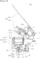
- FIG. 6 is a cross-sectional view illustrating a state in which the opening and closing part is open in a beverage extracting device according to an exemplary embodiment of the invention
- FIG. 7 is a cross-sectional view illustrating a state in which the opening and closing part is closing in a beverage extracting device according to an exemplary embodiment of the invention
- FIG. 8 is a cross-sectional view illustrating a state in which the opening and closing part is closed in a beverage extracting device according to an exemplary embodiment of the invention.
- the perforating part 500 is moved reciprocally due to rotation of the opening and closing part 300.
- the perforating part 500 may include the first punch 510 and a guide link 520.
- one side of the first punch 510 may be inserted inside of the discharging member 230 through the insertion hole 233 of the discharging member 230.
- a diameter of the insertion hole 233 is formed to be narrower downwards, and the stopper 511 having a shape corresponding to a shape of the insertion hole 233 is provided in one side of the first punch 510.
- the first punch 510 is prevented from falling out from the insertion hole 233.
- One side of the guide link 520 may be connected to the extracting part 200 to be rotated, and the other side of the guide link 520 may be connected to the other side of the first punch 510 to be rotated.
- the other side of the guide link 520 may be rotated based on one side of the guide link 520.
- the other side of the guide link 520 is connected to the first punch 510, even when the other side of the guide link 520 is rotated by self weight, the first punch 510 may be stopped while being in close contact with the insertion hole 233, due to the stopper 511 of the first punch 510.
- the guide link 520 may not be further rotated and may be supported in a stopped state.
- a bottom of the guide link 520 may be formed to have a curved surface having a predetermined radius of curvature.
- the rotating shaft RS connected to the second link member 420 may be sliding-moved with respect to the bottom of the guide link 520.
- a first stopper protrusion 521 may be formed in a portion of the bottom the guide link 520, corresponding to one side of the guide link 520, and a second stopper protrusion 523 may be formed in a portion of the bottom of the guide link 520, corresponding to the other side of the guide link 520.
- the second link member 420 rotates in a clockwise direction, and thus, the rotating shaft RS connected to the second link member 420 may rotate in a clockwise direction.
- the rotating shaft RS is caught by the first stopper protrusion 521. Due to a force in which the rotating shaft RS pushes the first stopper protrusion 521, the other side of the guide link 520 may be rotated based on one side of the guide link 520.
- the first punch 510 connected to the other side of the guide link 520 is lifted upwards.
- the first punch 510 is inserted inside of the installing space MS.
- beverage capsule C installed inside of the installing space MS may be perforated.
- the guide link 520 rotates in a counter-clockwise direction, and thus, the first punch 510 connected to the other side of the guide link 520 may be moved downwards due to rotation of the guide link 520 in a counterclockwise direction.
- an elastic member 530 is provided in the perforating part 500.
- One side of the elastic member 530 may be fixed to the extracting part 200, and the other side of the elastic member 530 may be fixed to the guide link 520.
- the guide link 520 may rotationally reciprocating move, and the first punch 510 may linearly reciprocating move.
- the first punch 510 perforates the beverage capsule C
- the first punch moves downwards.
- enough space for discharging a beverage extracted from the beverage capsule C through a perforated portion of the beverage capsule may be secured.
- beverage powders are highly compressed inside of the beverage capsule C, thereby significantly lowering an extraction function of the beverage.
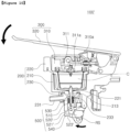
- FIG. 9 is a cross-sectional view illustrating a state in which the opening and closing part is open in a beverage extracting device according to another exemplary embodiment of the invention
- FIG. 10 is a cross-sectional view illustrating a state in which the opening and closing part is closing in a beverage extracting device according to another exemplary embodiment of the invention
- FIG. 11 is a cross-sectional view illustrating a state in which the opening and closing part is closed in a beverage extracting device according to another exemplary embodiment of the invention.
- a beverage extracting device 100' according to another exemplary embodiment of the invention is the same as the beverage extracting device 100 according to an exemplary embodiment of the invention except a guide link 520', descriptions will be omitted, other than with regard to the guide link 520'.
- a rotating link member 540 may be further included in the guide link 520'.
- an insertion groove 521' may be formed in a portion of a bottom of the guide link 520' corresponding to one side of the guide link 520', and the rotating link member 540 is inserted into the insertion groove 521'.
- one side of the rotating link member may be connected to the guide link 520' to be rotated.
- the insertion groove 521' may have a shape corresponding to a shape of the rotating link member 540.
- the other side of the rotating link member 540 is rotated based on one side of the rotating link member 540 by self weight, and thus, a portion of the other side of the rotating link member 540 may protrude outwardly of the guide link 520'.
- the rotating shaft RS pushes the other side of the rotating link member 540 protruding outwardly of the guide link 520', and thus, the guide link 540 is rotated.
- the first punch 510 is inserted inside of the installing space MS.
- the rotating shaft RS moves along a bottom of the guide link 520' to be seated on a stopper protrusion 523' of the guide link 520'.
- the rotating shaft RS moves along the bottom of the guide link 520' in a direction opposite to a direction in which the rotating shaft RS moves when the opening and closing part 300 is closed.
- the rotating shaft RS pushes the rotating link member 540 protruding outwardly of the guide link 520', and thus, the other side of the rotating link member 540 is rotated based on one side of the rotating link member 540 to be inserted inside of the insertion groove 521'.
- the rotating link member 540 allows movement of the rotating shaft RS not to be limited.
- the opening and closing part 300 may open with a small force.
- a beverage extracting device according to an exemplary embodiment in the present disclosure and a water purifier including the same may allow a beverage extracted from a beverage capsule to be easily discharged from the beverage capsule.
- a beverage extraction function may be improved.
Landscapes
- Engineering & Computer Science (AREA)
- Food Science & Technology (AREA)
- Chemical & Material Sciences (AREA)
- Mechanical Engineering (AREA)
- Life Sciences & Earth Sciences (AREA)
- Hydrology & Water Resources (AREA)
- Environmental & Geological Engineering (AREA)
- Water Supply & Treatment (AREA)
- Organic Chemistry (AREA)
- Chemical Kinetics & Catalysis (AREA)
- Apparatus For Making Beverages (AREA)
Description
- The present invention relates to a beverage extracting device and a water purifier including the same.
- A beverage extracting device is a device for extracting a beverage such as coffee, green tea, or the like to provide the beverage to a user.
- To this end, a beverage extracting device may use a beverage capsule in which beverage powder such as coffee, green tea, or the like is stored.
- In a beverage extracting device using a beverage capsule, hot water at a predetermined pressure is supplied from a hot water source to a beverage capsule, and thus, the hot water at a predetermined pressure is mixed with the beverage powder.
- In addition, as described above, when the hot water at a predetermined pressure is mixed with the beverage powder, a beverage is produced. In other words, a beverage can be extracted from a beverage capsule.
- As described above, a beverage is extracted from a beverage extracting device to be provided to a user.
- Generally, in a beverage extracting device, a beverage capsule is perforated using a separate punching member, or the like. In this case, after a beverage capsule is perforated by a punching member, the beverage capsule remains located inside the beverage extracting device. Therefore, a problem, in which it is difficult to discharge a beverage extracted from the beverage capsule through a perforated hole, may occur.
- Therefore, a problem in which beverage powder is highly compressed inside a beverage capsule and a beverage extraction function is significantly reduced may also occur.
-
EP 2 543 291 A1 discloses a brewing unit with an extracting part with an installing space for holding a beverage capsule, an opening and closing part connected to the extracting part to open and seal the installing space, a link part and a perforating part coupled to the link part for perforating the beverage capsule. -
KR 2009 0079832 A EP2000063 Al discloses a beverage extracting device comprising a reciprocating perforating part configured to perforate a capsule. - An aspect of the present disclosure may provide a beverage extracting device allowing a beverage, extracted from a beverage capsule, to be easily discharged from the beverage capsule, and a water purifier including the same.
- An aspect of the present disclosure may provide a beverage extracting device having an improved beverage extraction function and a water purifier including the same.
- The present invention is directed to a beverage extracting device according to independent claim 1, said beverage extracting device includes: an extracting part including an installing space in which a beverage capsule is installed; an opening and closing part connected to the extracting part, for opening or sealing the installing space;
a link part connected to at least one between the extracting part and the opening and closing part; and a perforating part moving reciprocally so as to perforate the beverage capsule due to movement of the link part. - The opening and closing part of the beverage extracting device according to an aspect of the present disclosure may be connected to the extracting part to be rotated.
- The link part of the beverage extracting device is coupled to the opening and closing part to be rotated.
- The perforating part of the beverage extracting device is configured to move reciprocally between an interior and an exterior of the installing space.
- The extracting part of the beverage extracting device includes a holder in which the installing space is formed, a body for accommodating the holder, and a discharging member installed below the body.
- The bottom surfaces of the holder and the body of the beverage extracting device are provided with discharge holes penetrating therethrough.
- The discharging member of the beverage extracting device is provided with an insertion hole into which the perforating part is inserted, and is provided with a discharge port through which a beverage extracted from the beverage capsule is discharged externally.
- The insertion hole of the beverage extracting device is formed to have a diameter narrower toward a lower portion, and the perforating part is provided with a stopper in a shape corresponding to a shape of the insertion hole.
- The opening and closing part of the beverage extracting device according to an aspect of the present disclosure may include a cover for opening or sealing the installing space and a lever member connected to the cover to be rotated.
- Due to the link part of the beverage extracting device according to an aspect of the present disclosure, rotational force of the lever member may be transmitted to the cover.
- The link part of the beverage extracting device according to an aspect of the present disclosure may include: a first link member coupled to the lever member to be rotated; a second link member coupled to the first link member to be rotated; and a third link member coupled to the second link member to be rotated.
- The link part of the beverage extracting device according to an aspect of the present disclosure may include: a first link member having one side connected to the lever member to be rotated; a second link member having one side connected to the body to be rotated; and a third link member having one side connected to the cover to be rotated, wherein the other side of the second link member may be connected to the other side of the first link member and the other side of the third link member to be rotated.
- The beverage extracting device according to an aspect of the present disclosure may further include a rotating shaft connected to the other side of the second link member.
- The perforating part of the beverage extracting device according to an aspect of the present disclosure may include: a guide link rotationally reciprocating due to rotation of the rotating shaft; and a first punch linearly reciprocating due to rotationally reciprocating motion of the guide link.
- One side of the guide link of the beverage extracting device according to an aspect of the present disclosure may be connected to the extracting part to be rotated, and the other side of the guide link may be connected to the first punch to be rotated.
- A portion of a bottom of the guide link of the beverage extracting device according to an aspect of the present disclosure, corresponding to one side of the guide link, may be provided with a first stopper protrusion formed therein, and a portion thereof, corresponding to the other side of the guide link, may be provided with a second stopper protrusion formed therein.
- In a portion of a bottom of the guide link of the beverage extracting device according to an aspect of the present disclosure, corresponding to one side of the guide link, an insertion groove may be formed therein, and a rotating link member may be inserted into the insertion groove to be connected to the guide link to be rotated.
- A portion of the rotating link member of the beverage extracting device according to an aspect of the present disclosure may protrude outwardly of the guide link by self weight.
- A bottom of the guide link of the beverage extracting device according to an aspect of the present disclosure may be formed to have a curved surface, and the rotating shaft may move slidingly with respect to the bottom of the guide link.
- The first punch of the beverage extracting device according to an aspect of the present disclosure may linearly reciprocate between an interior and an exterior of the installing space.
- According to another aspect of the present disclosure, a water purifier includes: a beverage extracting device; a housing for accommodating the beverage extracting device; and a beverage extraction port provided in the housing to discharge a beverage extracted from the beverage extracting device.
- The beverage extracting device according to another aspect of the present disclosure may further include: a cold-purified water extraction port provided in the housing to discharge cold-purified water; and a hot water discharge port provided in the housing to discharge hot water.
- According to an exemplary embodiment in the present disclosure, a beverage extracting device and a water purifier including the same may easily discharge a beverage, extracted from a beverage capsule, from the beverage capsule.
- In addition, a beverage extraction function may be improved.
-
-
FIG. 1 is a perspective view of a water purifier according to an exemplary embodiment of the invention. -
FIG. 2 is an exploded perspective view of a beverage extracting device according to an exemplary embodiment of the invention. -
FIG. 3 is a perspective view illustrating a state in which an opening and closing part of a beverage extracting device according to an exemplary embodiment of the invention is open. -
FIG. 4 is a perspective view illustrating a state in which an opening and closing part of a beverage extracting device according to an exemplary embodiment of the invention is closing. -
FIG. 5 is a perspective view illustrating a state in which an opening and closing part of a beverage extracting device according to an exemplary embodiment of the invention is closed. -
FIG. 6 is a cross-sectional view illustrating a state in which the opening and closing part in the beverage extracting device according to an exemplary embodiment of the invention is open. -
FIG. 7 is a cross-sectional view illustrating a state in which the opening and closing part in the beverage extracting device according to an exemplary embodiment of the invention is closing. -
FIG. 8 is a cross-sectional view illustrating a state in which the opening and closing part in the beverage extracting device according to an exemplary embodiment of the invention is closed. -
FIG. 9 is a cross-sectional view illustrating a state in which the opening and closing part in a beverage extracting device according to another exemplary embodiment of the invention is open. -
FIG. 10 is a cross-sectional view illustrating a state in which the opening and closing part in the beverage extracting device according to another exemplary embodiment of the invention is closing. -
FIG. 11 is a cross-sectional view illustrating a state in which the opening and closing part in the beverage extracting device according to another exemplary embodiment of the invention is closed. - Hereinafter, specific embodiments of the present invention will be described in detail with reference to the drawings.
- In addition, throughout the specification, a configuration is referred to as being 'connected' to another configuration, including not only when the configurations are 'directly connected' but also when they are 'indirectly connected' to each other. Also, some components are 'included' , means that it would be possible not to exclude other components 8 but to further include other components not otherwise specifically stated as long as the resulting embodiment falls within the scope of the appended claims.
- The same components have the same functions in the scope of the same idea illustrated in the drawings of each embodiment will be described using the same reference numerals.
-
FIG. 1 is a perspective view of a water purifier according to an exemplary embodiment in the present disclosure. - With reference to
FIG. 1 , a water purifier according to an exemplary embodiment in the present disclosure may include ahousing 10, abeverage extracting device 100 inserted into and fixed to thehousing 10, and abeverage extraction port 20 provided in thehousing 10 to be connected to thebeverage extracting device 100. - In addition, the water purifier may further include a cold-purified water extraction port 30 from which cold-purified water is discharged and a hot water extraction port 40 from which hot water is discharged.
- The
housing 10 may form an exterior of the water purifier according to an exemplary embodiment in the present disclosure, and the cold-purified water extraction port 30 and the hot water extraction port 40 may be provided in front of the water purifier. - Moreover, in addition to the cold-purified water extraction port 30 and the hot water extraction port 40, the
beverage extraction port 20 is provided therein. Through thebeverage extraction port 20, a beverage extracted from thebeverage extracting device 100 may be discharged externally. - Thus, a user may drink cold water, purified water, or hot water according to preference, or may drink a beverage extracted from the beverage extracting device.
- Hereinafter, with reference to
FIGS. 2 to 11 , thebeverage extracting device 100 will be described. -
FIG. 2 is an exploded perspective view of a beverage extracting device according to an exemplary embodiment of the invention,FIG. 3 is a perspective view illustrating a state in which an opening and closing part of a beverage extracting device according to an exemplary embodiment of the invention is open,FIG. 4 is a perspective view illustrating a state in which an opening and closing part of a beverage extracting device according to an exemplary embodiment of the invention is closing, andFIG. 5 is a perspective view illustrating a state in which an opening and closing part of a beverage extracting device according to an exemplary embodiment of the invention is closed. - With reference to
FIGS. 2 to 5 , abeverage extracting device 100 according to an exemplary embodiment of the invention includes an extractingpart 200, an opening and closingpart 300, alink part 400, and a perforatingpart 500. - First, the
beverage extracting device 100 according to an exemplary embodiment of the invention will be schematically described. - An installing space MS is provided in the extracting
part 200, and a beverage capsule C may be installed in the installing space MS. The opening and closingpart 300 is connected to the extractingpart 200 so as to open or seal the installing space MS. - For example, the opening and closing
part 300 is connected to the extractingpart 200 to be rotated. When the opening and closingpart 300 is closed, the installing space MS may be sealed. When the opening and closingpart 300 is open, the installing space MS may be open. - The beverage capsule C is installed in the installing space MS, and high-pressure hot water may be provided for the beverage capsule C through the opening and closing
part 300, while the installing space MS is sealed. - When the opening and closing
part 300 is closed, the beverage capsule C is perforated by the perforatingpart 500, and thus, a beverage may be extracted from the beverage capsule C. - To perforate the beverage capsule C, the perforating
part 500 includes afirst punch 510. - The beverage extracted from the beverage capsule C may be is discharged externally through the extracting
part 200. - In this case, even when high pressure is applied to the installing space MS, not to open the opening and closing
part 300, but to maintain a state in which the installing space MS is sealed, thelink part 400 may be provided. - Hereinafter, with reference to
FIGS. 2 to 5 , each configuration will be described in detail. - The extracting
part 200 includes abody 210, aholder 220, and a dischargingmember 230. - A seat groove 211 allowing the
holder 220 to be seated thereon may be provided in thebody 210, and theholder 220 may be inserted into the seat groove 211 to be seated thereon. - The installing space MS is formed in the
holder 220, and the beverage capsule C is installed in the installing space MS. To this end, an upper part of the installing space MS may be open and the installing space MS may have a shape corresponding to that of the beverage capsule C. - Since the beverage capsule C is inserted into the installing space MS from the open upper part of the installing space MS, the beverage capsule may be installed in the installing space MS.
- Discharge holes 213 and 221 penetrate through a bottom surface of the seat groove 211 and a bottom surface of the
holder 220 to be formed in positions corresponding thereto, respectively, and thus, a beverage extracted from the beverage capsule C is discharged therethrough. - The discharging
member 230 is installed below thebody 210, and adischarge port 231 from which the beverage is discharged is provided therein. - The beverage is provided for the discharging
member 230 through the discharge holes 213 and 221 formed in the bottom surface of the seat groove 211 and the bottom surface of theholder 220, respectively, and the beverage is discharged externally through thedischarge port 231. - In addition, an
insertion hole 233 is penetrated through and formed in the dischargingmember 230, and thefirst punch 510 is disposed in theinsertion hole 233. - Here, a diameter of the
insertion hole 233 is formed to be narrower downwardly, and thefirst punch 510 is provided with astopper 511 having a shape corresponding to a shape of theinsertion hole 233. Thus, theinsertion hole 233 is configured to be sealed by thefirst punch 510. - The
first punch 510 is disposed to be reciprocating moved, and thefirst punch 510 moves inside of the installing space MS through the discharge holes 213 and 221 to perforate the beverage capsule C. In addition, after thefirst punch 510 perforates the beverage capsule C, the first punch moves outside of the installing space MS, and thus, thestopper 511 allows theinsertion hole 233 to be sealed thereby. - Thus, the beverage provided for the discharging
member 230 not discharged externally through theinsertion hole 233, and is discharged externally through thedischarge port 231. - A reciprocating motion of the
first punch 510 will be described later with respect toFIGS. 6 to 8 . - The opening and closing
part 300 is connected to the extractingpart 200 to open or seal the installing space MS. - To this end, the opening and closing
part 300 may include acover 310 and alever member 320. - The
cover 310 may be coupled to thelever member 320 to be rotated depending on a location of thelever member 320 so as to open and close the open upper part of the installing space MS. - Thus, as illustrated in
FIG. 5 , the installing space MS may be sealed, or as illustrated inFIGS. 3 and4 , the installing space MS may be open. - To allow the
cover 310 to be coupled to thelever member 320 and to be rotated, thecover 310 may be connected to thelever member 320. - In addition, each of the
cover 310 and thelever member 320 may be connected to thebody 210, as illustrated inFIGS. 3 to 5 . - For example, each of the
cover 310 and thelever member 320 may be connected to thebody 210 by a connecting pin P to be rotated. Thus, thecover 310 and thelever member 320, as illustrated inFIGS. 3 to 5 , may be rotated based on the connecting pin P. - When a user applies force upwardly to the
lever member 320, to open an upper part of the installing space MS, thecover 310 may be rotated with thelever member 320. - In addition, in the state described above, when a user applies a force downwardly the
lever member 320, to allow the upper part of the installing space MS to be closed by thecover 310, thecover 310 may be rotated with thelever member 320. Thus, while the beverage capsule C is installed in the installing space MS, the installing space MS may be sealed. - Meanwhile, when the installing space MS is sealed, to perforate an upper part of the beverage capsule C installed in the installing space MS, a
second punch 311 may be provided in thecover 310. - As a tip of the
second punch 311 is formed to be sharpened, the beverage capsule C may be perforated thereby. As hot watersupply flow paths cover 310 and thesecond punch 311, high-pressure hot water may be provided for the beverage capsule C through the hot watersupply flow paths - While the installing space MS is sealed, even when high pressure is applied to the installing space MS, the
link part 400 may serve to allow the opening and closingpart 300 not to be open. - To this end, the
link part 400 may include afirst link member 410, asecond link member 420, and athird link member 430. - One side of the
first link member 410 may be connected to thelever member 320 to be rotated, one side of thesecond link member 420 may be connected to thebody 210 to be rotated, and one side of thethird link member 430 may be connected to thecover 310 to be rotated. - In addition, the other side of the
second link member 420 may be connected to the other side of thefirst link member 410 and the other side of thethird link member 430 to be rotated. - Thus, the
first link member 410, thesecond link member 420, and thethird link member 430 may be coupled to the opening and closingpart 300 to be rotated. - For example, due to an operation of the
lever member 320, the other side of thefirst link member 410 is rotated based on one side of thefirst link member 410, and thus, the other side of thesecond link member 420 is rotated based on one side of thesecond link member 420. Thus, the other side of thethird link member 430 may be rotated based on one side of thethird link member 430. - Meanwhile, as illustrated in
FIG. 5 , when the opening and closingpart 300 allows the installing space MS to be sealed, a second center virtual line L2 extended from one side of thesecond link member 420 to the other side thereof may be located between a first center virtual line L1 extended from one side of thefirst link member 410 to the other side thereof and a third center virtual line L3 extended from one side of thethird link member 430 to the other side thereof. - Thus, a direction of rotation of the
second link member 420 due to movement of thefirst link member 410 when thelever member 320 is lifted up, may be different from a direction of rotation of thesecond link member 420 due to movement of thethird link member 430 when thecover 310 is pushed up by applying high pressure to the installing space MS. - In addition, the third center virtual line L3 may be positioned closer to the
discharge port 231 of the extractingpart 200 than the first center virtual line L1. - Thus, as illustrated in
FIGS. 4 and5 , while the installing space MS is sealed by thecover 310, when thelever member 320 is lifted up, a direction of rotation of thesecond link member 420 due to movement of thefirst link member 410 may be a counterclockwise direction based onFIGS. 4 and5 . Thus, when thelever member 320 is lifted up, thecover 310 may be open. - Alternatively, when the
lever member 320 is lowered to seal the installing space MS, a direction of rotation of thesecond link member 420 may be a clockwise direction based onFIGS. 4 and5 . Thus, when thelever member 320 is lowered, thecover 310 may be closed. - In addition, as illustrated in
FIG. 5 , while the installing space MS is sealed by thecover 310, when high pressure is applied to the installing space MS, a force is applied to a direction in which thecover 310 is lifted up. In this case, a direction of rotation of thesecond link member 420 due to movement of thethird link member 430 may be a clockwise direction based onFIG. 5 . - Thus, the
cover 310 may further close the upper part of installing space MS due to thethird link member 430. - In addition, a sawtooth-shaped groove 431 may be formed in the
third link member 430, and a sawtooth-shaped groove 215 may be formed in thebody 210. Thus, when the installing space MS is sealed by thecover 310, thethird link member 430 may be engaged with thebody 210. - When a force is applied in a direction in which the
cover 310 is lifted by high pressure applied to the installing space MS, while thesecond link member 420 rotates in a clockwise direction, thethird link member 430 is pulled thereby. Thus, thethird link member 430 is more closely attached to thebody 210. As a result, even when high pressure is applied to the installing space MS, thecover 310 may not be open. - Meanwhile, the
first link member 410, thesecond link member 420, and thethird link member 430 may be provided as pairs to be symmetrical to each other on both sides of the extractingpart 200 and the opening and closingpart 300. - In the other side of the
second link member 420, a rotating shaft RS for connecting twosecond link members 420 to each other may be provided therein. - Hereinafter, with reference to
FIGS. 6 to 8 , due to rotation of the opening and closingpart 300, an operation in which the perforatingpart 500 moves reciprocally will be described. -
FIG. 6 is a cross-sectional view illustrating a state in which the opening and closing part is open in a beverage extracting device according to an exemplary embodiment of the invention,FIG. 7 is a cross-sectional view illustrating a state in which the opening and closing part is closing in a beverage extracting device according to an exemplary embodiment of the invention andFIG. 8 is a cross-sectional view illustrating a state in which the opening and closing part is closed in a beverage extracting device according to an exemplary embodiment of the invention. - With reference to
FIGS. 6 to 8 , the perforatingpart 500 is moved reciprocally due to rotation of the opening and closingpart 300. - To this end, the perforating
part 500 may include thefirst punch 510 and aguide link 520. - First, with reference to
FIG. 6 , one side of thefirst punch 510 may be inserted inside of the dischargingmember 230 through theinsertion hole 233 of the dischargingmember 230. - As described previously, a diameter of the
insertion hole 233 is formed to be narrower downwards, and thestopper 511 having a shape corresponding to a shape of theinsertion hole 233 is provided in one side of thefirst punch 510. Thus, thefirst punch 510 is prevented from falling out from theinsertion hole 233. - One side of the
guide link 520 may be connected to the extractingpart 200 to be rotated, and the other side of theguide link 520 may be connected to the other side of thefirst punch 510 to be rotated. - By self weight of the
guide link 520, the other side of theguide link 520 may be rotated based on one side of theguide link 520. However, since the other side of theguide link 520 is connected to thefirst punch 510, even when the other side of theguide link 520 is rotated by self weight, thefirst punch 510 may be stopped while being in close contact with theinsertion hole 233, due to thestopper 511 of thefirst punch 510. - Thus, the
guide link 520 may not be further rotated and may be supported in a stopped state. - Meanwhile, a bottom of the
guide link 520 may be formed to have a curved surface having a predetermined radius of curvature. - When the
second link member 420 is rotated in a clockwise direction or in a counter-clockwise direction due to an operation of the opening and closingpart 300, the rotating shaft RS connected to thesecond link member 420 may be sliding-moved with respect to the bottom of theguide link 520. - In addition, a
first stopper protrusion 521 may be formed in a portion of the bottom theguide link 520, corresponding to one side of theguide link 520, and asecond stopper protrusion 523 may be formed in a portion of the bottom of theguide link 520, corresponding to the other side of theguide link 520. - With reference to
FIG. 7 , when the opening and closingpart 300 is closed, thesecond link member 420 rotates in a clockwise direction, and thus, the rotating shaft RS connected to thesecond link member 420 may rotate in a clockwise direction. - In this case, the rotating shaft RS is caught by the
first stopper protrusion 521. Due to a force in which the rotating shaft RS pushes thefirst stopper protrusion 521, the other side of theguide link 520 may be rotated based on one side of theguide link 520. - Since the other side of the
guide link 520 rotates, thefirst punch 510 connected to the other side of theguide link 520 is lifted upwards. In this case, thefirst punch 510 is inserted inside of the installing space MS. - Thus, the beverage capsule C installed inside of the installing space MS may be perforated.
- Next, as illustrated in
FIG. 8 , when the opening and closingpart 300 is closed to seal the installing space MS, the rotating shaft RS moves slidingly along a bottom of theguide link 520, and thus, the rotating shaft is seated on thesecond stopper protrusion 523. - In this case, the
guide link 520 rotates in a counter-clockwise direction, and thus, thefirst punch 510 connected to the other side of theguide link 520 may be moved downwards due to rotation of theguide link 520 in a counterclockwise direction. - To this end, an
elastic member 530 is provided in the perforatingpart 500. - One side of the
elastic member 530 may be fixed to the extractingpart 200, and the other side of theelastic member 530 may be fixed to theguide link 520. - Thus, as illustrated in
FIG. 8 , while the rotating shaft RS moves slidingly along the bottom of theguide link 520, the other side of theguide link 520 is rotated in a counter-clockwise direction due to an elastic force of theelastic member 530, and thus, thefirst punch 510 is in close contact with theinsertion hole 233 while moving downwardly. - In other words, due to an operation of the opening and closing
part 300, theguide link 520 may rotationally reciprocating move, and thefirst punch 510 may linearly reciprocating move. - In the
beverage extracting device 100 according to an exemplary embodiment in the present disclosure, after thefirst punch 510 perforates the beverage capsule C, the first punch moves downwards. Thus, enough space for discharging a beverage extracted from the beverage capsule C through a perforated portion of the beverage capsule may be secured. - In the case in which the space for discharging a beverage extracted from the beverage capsule C is not secured, beverage powders are highly compressed inside of the beverage capsule C, thereby significantly lowering an extraction function of the beverage.
- However, in the
beverage extracting device 100 according to an exemplary embodiment in the present disclosure, since enough space for discharging a beverage extracted from the beverage capsule C through the perforated portion of the beverage capsule is secured, an extraction function of the beverage may be improved. -
FIG. 9 is a cross-sectional view illustrating a state in which the opening and closing part is open in a beverage extracting device according to another exemplary embodiment of the invention,FIG. 10 is a cross-sectional view illustrating a state in which the opening and closing part is closing in a beverage extracting device according to another exemplary embodiment of the invention, andFIG. 11 is a cross-sectional view illustrating a state in which the opening and closing part is closed in a beverage extracting device according to another exemplary embodiment of the invention. - A beverage extracting device 100' according to another exemplary embodiment of the invention is the same as the
beverage extracting device 100 according to an exemplary embodiment of the invention except a guide link 520', descriptions will be omitted, other than with regard to the guide link 520'. - In another exemplary embodiment in the present disclosure, a
rotating link member 540 may be further included in the guide link 520'. - To this end, an
insertion groove 521' may be formed in a portion of a bottom of the guide link 520' corresponding to one side of the guide link 520', and therotating link member 540 is inserted into theinsertion groove 521'. Thus, one side of the rotating link member may be connected to the guide link 520' to be rotated. - The
insertion groove 521' may have a shape corresponding to a shape of therotating link member 540. - In this case, the other side of the
rotating link member 540 is rotated based on one side of therotating link member 540 by self weight, and thus, a portion of the other side of therotating link member 540 may protrude outwardly of the guide link 520'. - Thus, when the opening and closing
part 300 is closed, the rotating shaft RS pushes the other side of therotating link member 540 protruding outwardly of the guide link 520', and thus, theguide link 540 is rotated. Thus, due to rotation of theguide link 520, thefirst punch 510 is inserted inside of the installing space MS. - Until the installing space MS is sealed by closing the opening and closing
part 300, the rotating shaft RS moves along a bottom of the guide link 520' to be seated on a stopper protrusion 523' of the guide link 520'. - When the opening and closing
part 300, which is closed, is open, the rotating shaft RS moves along the bottom of the guide link 520' in a direction opposite to a direction in which the rotating shaft RS moves when the opening and closingpart 300 is closed. - In this case, the rotating shaft RS pushes the
rotating link member 540 protruding outwardly of the guide link 520', and thus, the other side of therotating link member 540 is rotated based on one side of therotating link member 540 to be inserted inside of theinsertion groove 521'. - Due to a structure described above, when the opening and closing
part 300 is open, therotating link member 540 allows movement of the rotating shaft RS not to be limited. Thus, the opening and closingpart 300 may open with a small force. - Through the exemplary embodiments described above, a beverage extracting device according to an exemplary embodiment in the present disclosure and a water purifier including the same may allow a beverage extracted from a beverage capsule to be easily discharged from the beverage capsule.
- In addition, a beverage extraction function may be improved.
- While the present invention has been particularly shown and described with reference to exemplary embodiments thereof, but is not limited thereto. It is apparent to those skilled in the art that various changes and modifications thereof may be made without departing from the scope of the appended claims.
Claims (12)
- A beverage extracting device (100), comprising:- an extracting part (200) including an installing space (MS) in which a beverage capsule (C) is installed;- an opening and closing part (300) connected to the extracting part, for opening or sealing the installing space;- a link part (400) connected between the extracting part and the opening and closing part; and- a perforating part (500) moving reciprocally so as to perforate the beverage capsule due to rotation of the opening and closing part (300), wherein the perforating part (500) moves reciprocally between an interior and an exterior of the installing space (MS), and,when the opening and closing part (300) is moved to seal the installing space (MS), the perforating part (500) is configured to be inserted into the interior of the installing space (MS) to perforate the beverage capsule (C) and the perforating part (500) is configured to be moved to the exterior of the installing space (MS) after perforating the beverage capsule (C),characterized in thatthe extracting part (200) includes a holder (220) in which the installing space (MS) is formed, a body (210) for accommodating the holder (220), and a discharging member (230) installed below the body;wherein bottom surfaces of the holder (220) and the body (210) are provided with discharge holes (213, 221) penetrating therethrough into which the perforating part (500) is configured to be inserted;wherein the discharging member (230) is provided with an insertion hole (233) into which the perforating part (500) is inserted, and is provided with a discharge port (231) through which a beverage extracted from the beverage capsule is discharged externally;wherein the insertion hole (233) is formed to have a diameter narrower toward a lower portion, and the perforating part comprises a first punch (510) provided with a stopper (511) having a shape corresponding to a shape of the insertion hole, andwherein when the perforating part (500) is moved to the exterior of the installing space (MS) after perforating the beverage capsule (C), the insertion hole (233) is configured to be sealed by the stopper (511).
- The beverage extracting device of claim 1, wherein the opening and closing part (300) is connected to the extracting part (200) to be rotated,
the link part (400) is coupled to the opening and closing part to be rotated. - The beverage extracting device of claim 1, wherein the opening and closing part (300) includes a cover (310) for opening or sealing the installing space (MS) and a lever member (320) connected to the cover to be rotated,
due to the link part (400), rotational force of the lever member is transmitted to the cover. - The beverage extracting device of claim 3, wherein the link part (400) includes:- a first link member (410) coupled to the lever member (320) to be rotated;- a second link member (420) coupled to the first link member to be rotated; and- a third link member (430) coupled to the second link member to be rotated.
- The beverage extracting device of claim 3, wherein the link part (400) includes:- a first link member (410) having one side connected to the lever member (320) to be rotated;- a second link member (420) having one side connected to the body (210) to be rotated; and- a third link member (430) having one side connected to the cover (310) to be rotated,wherein the other side of the second link member is connected to the other side of the first link member and the other side of the third link member to be rotated.
- The beverage extracting device of claim 5, further comprising a rotating shaft (RS) connected to the other side of the second link member (420).
- The beverage extracting device of claim 6, wherein the perforating part (500) includes:- a guide link (520, 520') rotationally reciprocating due to rotation of the rotating shaft (RS); andwherein the first punch (510) linearly reciprocates due to rotationally reciprocating motion of the guide link.
- The beverage extracting device of claim 7, wherein one side of the guide link (520, 520') is connected to the extracting part (200) to be rotated, and the other side of the guide link is connected to the first punch (510) to be rotated.
- The beverage extracting device of claim 8, wherein a portion of a bottom of the guide link (520), corresponding to one side of the guide link, is provided with a first stopper protrusion (521) formed therein, and a portion thereof, corresponding to the other side of the guide link, is provided with a second stopper protrusion (523) formed therein.
- The beverage extracting device of claim 8, wherein, in a portion of a bottom of the guide link (520'), corresponding to one side of the guide link, an insertion groove (521') is formed therein, and a rotating link member (540) is inserted into the insertion groove to be connected to the guide link to be rotated,
a portion of the rotating link member protrudes outwardly of the guide link by self weight. - The beverage extracting device of claim 7, wherein a bottom of the guide link (520, 520') is formed to have a curved surface, and the rotating shaft (RS) moves slidingly with respect to the bottom of the guide link,
the first punch linearly reciprocates between an interior and an exterior of the installing space. - A water purifier, comprising:- the beverage extracting device (100) according to one of claims 1 to 11;- a housing (10) for accommodating the beverage extracting device; and- a beverage extraction port (20) provided in the housing to discharge a beverage extracted from the beverage extracting device;- a cold-purified water extraction port (30) provided in the housing to discharge cold-purified water; and- a hot water discharge port (40) provided in the housing to discharge hot water.
Applications Claiming Priority (2)
| Application Number | Priority Date | Filing Date | Title |
|---|---|---|---|
| KR1020140121398A KR102292862B1 (en) | 2014-09-12 | 2014-09-12 | Beverage extracting apparatus and water purifier including the same |
| PCT/KR2015/009076 WO2016039543A1 (en) | 2014-09-12 | 2015-08-28 | Beverage extracting device and water purifier including same |
Publications (4)
| Publication Number | Publication Date |
|---|---|
| EP3192408A1 EP3192408A1 (en) | 2017-07-19 |
| EP3192408A4 EP3192408A4 (en) | 2017-09-13 |
| EP3192408C0 EP3192408C0 (en) | 2025-02-12 |
| EP3192408B1 true EP3192408B1 (en) | 2025-02-12 |
Family
ID=55459260
Family Applications (1)
| Application Number | Title | Priority Date | Filing Date |
|---|---|---|---|
| EP15840407.9A Active EP3192408B1 (en) | 2014-09-12 | 2015-08-28 | Beverage extracting device and water purifier including same |
Country Status (5)
| Country | Link |
|---|---|
| US (1) | US10973365B2 (en) |
| EP (1) | EP3192408B1 (en) |
| KR (1) | KR102292862B1 (en) |
| CN (1) | CN106687013B (en) |
| WO (1) | WO2016039543A1 (en) |
Families Citing this family (32)
| Publication number | Priority date | Publication date | Assignee | Title |
|---|---|---|---|---|
| KR102603456B1 (en) * | 2016-07-22 | 2023-11-17 | 엘지전자 주식회사 | Coffee extraction device |
| IT201600126287A1 (en) * | 2016-12-14 | 2018-06-14 | Caffitaly System Spa | Equipment for the preparation of a drink by infusing a food substance with water |
| USD846934S1 (en) * | 2017-06-14 | 2019-04-30 | Barsys LLC | Beverage mixer dispenser |
| ES2934859T3 (en) | 2018-03-14 | 2023-02-27 | Nestle Sa | Beverage extraction unit for selectively providing holes of different types in a capsule for the extraction of the beverage |
| USD893236S1 (en) * | 2018-11-21 | 2020-08-18 | Pepsico, Inc. | Dispenser |
| USD948904S1 (en) * | 2018-12-24 | 2022-04-19 | Cuckoo Homesys Co., Ltd. | Water purifier |
| USD973835S1 (en) * | 2019-08-30 | 2022-12-27 | Coway Co., Ltd. | Water purifier |
| USD1047560S1 (en) * | 2019-10-09 | 2024-10-22 | Franke Kaffeemaschinen Ag | Coffee machine |
| CN110713283A (en) * | 2019-10-12 | 2020-01-21 | 李海洋 | Medical wastewater multi-stage treatment process |
| USD950293S1 (en) * | 2020-03-11 | 2022-05-03 | CASO Holding GmbH | Hot water boiler |
| CA201163S (en) * | 2020-07-09 | 2022-05-20 | Smeg Spa | Espresso coffee machine |
| CN111760371B (en) * | 2020-08-06 | 2025-03-25 | 唯赛勃环保设备有限公司 | A composite water purifier |
| USD960288S1 (en) * | 2020-08-12 | 2022-08-09 | Clover Co., Ltd. | Water purification device |
| USD999336S1 (en) * | 2021-02-10 | 2023-09-19 | Coway Co., Ltd. | Water purifier |
| USD1025287S1 (en) * | 2021-09-08 | 2024-04-30 | Ceragem Co., Ltd. | Water purifier |
| USD1027532S1 (en) * | 2021-09-29 | 2024-05-21 | Coway Co., Ltd. | Water purifier |
| USD984190S1 (en) * | 2021-11-18 | 2023-04-25 | Tchibo Gmbh | Coffee machine |
| USD1016214S1 (en) * | 2022-01-17 | 2024-02-27 | Kingworks (Shenzhen) Industrial Co., Ltd. | Water purifier |
| TWD223655S (en) * | 2022-03-23 | 2023-02-11 | 以色列商蘇打流實業有限公司 | Part of domestic soda-water preparing device |
| CA216015S (en) | 2022-04-15 | 2024-06-25 | Brita Lp | Filter unit |
| USD1072162S1 (en) * | 2022-04-15 | 2025-04-22 | Brita Lp | Water purification device |
| USD1071634S1 (en) * | 2022-12-15 | 2025-04-22 | Breville Pty Limited | Water purifier |
| USD1041224S1 (en) * | 2022-12-28 | 2024-09-10 | De'Longhi Appliances S.R.L. Con Unico Socio | Coffee maker |
| US20240285129A1 (en) * | 2023-02-23 | 2024-08-29 | Conair Llc | Food blender and scraper assembly for a food blender |
| USD1072168S1 (en) * | 2023-03-01 | 2025-04-22 | Qingdao Ecopure Filter Co., Ltd. | Water purifying machine |
| USD1048334S1 (en) | 2023-05-05 | 2024-10-22 | Brita Lp | Water purification device |
| USD1040591S1 (en) * | 2023-05-25 | 2024-09-03 | A. S. Marketing Systems Ltd | Water dispenser |
| USD1118238S1 (en) * | 2023-07-14 | 2026-03-17 | Lg Electronics Inc. | Water purifier |
| USD1048791S1 (en) * | 2023-11-01 | 2024-10-29 | Strauss Water Ltd. | Water purification filtration and heating dispenser |
| CA233464S (en) * | 2024-03-22 | 2025-06-17 | Coway Co Ltd | Water purifier |
| TWD238633S (en) * | 2024-03-22 | 2025-06-01 | 韓商豪威股份有限公司 (南韓) | Portions of water purifier |
| CA233463S (en) * | 2024-03-22 | 2025-06-17 | Coway Co Ltd | Water purifier |
Citations (4)
| Publication number | Priority date | Publication date | Assignee | Title |
|---|---|---|---|---|
| US20050160919A1 (en) * | 2004-01-28 | 2005-07-28 | Werner Balkau | Brewing device for a coffee maker |
| EP2000063A1 (en) * | 2007-06-05 | 2008-12-10 | Criali Investment SA | Method for preparing a drink and apparatus and capsule for application of this method |
| KR20090079832A (en) * | 2008-01-18 | 2009-07-22 | 네스텍 소시에테아노님 | Punching elements for opening devices of beverage machines and beverage machines |
| WO2013042011A1 (en) * | 2011-09-19 | 2013-03-28 | Caffita System S.P.A. | Infusion device for making beverages using cartridges |
Family Cites Families (9)
| Publication number | Priority date | Publication date | Assignee | Title |
|---|---|---|---|---|
| ITFI20060194A1 (en) | 2006-08-04 | 2008-02-05 | Saeco Ipr Ltd | INFUSION DEVICE FOR THE PREPARATION OF DRINKS FROM SINGLE-DOSE CAPSULES |
| EP2238878A1 (en) * | 2009-04-09 | 2010-10-13 | Nestec S.A. | Beverage preparation device having a closing mechanism with force demultiplying means |
| CN201743493U (en) * | 2010-02-08 | 2011-02-16 | 广东亿龙电器股份有限公司 | Device for extracting drink from capsule |
| EP2543291A1 (en) | 2011-07-08 | 2013-01-09 | Koninklijke Philips Electronics N.V. | Brewing unit with a water heater |
| EP2543290A1 (en) | 2011-07-08 | 2013-01-09 | Koninklijke Philips Electronics N.V. | Brewing unit with a water heater |
| ITTO20120503A1 (en) | 2012-06-08 | 2013-12-09 | Lavazza Luigi Spa | DISPENSING UNIT FOR MACHINES FOR THE PREPARATION OF DRINKS BY CAPSULES |
| KR101430495B1 (en) | 2012-09-17 | 2014-08-14 | 엘지전자 주식회사 | Water Purifier |
| KR102064177B1 (en) | 2012-11-09 | 2020-01-09 | 웅진코웨이 주식회사 | Coffee capsule mounting/dismounting structure |
| CN203609280U (en) * | 2013-08-30 | 2014-05-28 | 漳州灿坤实业有限公司 | Automatic puncture mechanism of capsule coffee machine |
-
2014
- 2014-09-12 KR KR1020140121398A patent/KR102292862B1/en active Active
-
2015
- 2015-08-28 WO PCT/KR2015/009076 patent/WO2016039543A1/en not_active Ceased
- 2015-08-28 CN CN201580048940.0A patent/CN106687013B/en active Active
- 2015-08-28 EP EP15840407.9A patent/EP3192408B1/en active Active
- 2015-08-28 US US15/510,481 patent/US10973365B2/en active Active
Patent Citations (4)
| Publication number | Priority date | Publication date | Assignee | Title |
|---|---|---|---|---|
| US20050160919A1 (en) * | 2004-01-28 | 2005-07-28 | Werner Balkau | Brewing device for a coffee maker |
| EP2000063A1 (en) * | 2007-06-05 | 2008-12-10 | Criali Investment SA | Method for preparing a drink and apparatus and capsule for application of this method |
| KR20090079832A (en) * | 2008-01-18 | 2009-07-22 | 네스텍 소시에테아노님 | Punching elements for opening devices of beverage machines and beverage machines |
| WO2013042011A1 (en) * | 2011-09-19 | 2013-03-28 | Caffita System S.P.A. | Infusion device for making beverages using cartridges |
Also Published As
| Publication number | Publication date |
|---|---|
| EP3192408A4 (en) | 2017-09-13 |
| CN106687013B (en) | 2019-05-10 |
| WO2016039543A1 (en) | 2016-03-17 |
| CN106687013A (en) | 2017-05-17 |
| KR102292862B1 (en) | 2021-08-25 |
| US20170280921A1 (en) | 2017-10-05 |
| US10973365B2 (en) | 2021-04-13 |
| EP3192408A1 (en) | 2017-07-19 |
| EP3192408C0 (en) | 2025-02-12 |
| KR20160031686A (en) | 2016-03-23 |
Similar Documents
| Publication | Publication Date | Title |
|---|---|---|
| EP3192408A1 (en) | Beverage extracting device and water purifier including same | |
| JP6211741B1 (en) | Infusion unit | |
| TWI482606B (en) | Beverage machine and method for brewing ingredients using beverage machine | |
| EP2833766B1 (en) | Brewing assembly for brewed beverage vending machines | |
| RU2589576C2 (en) | Brewing device for food product preparation | |
| CN104780815A (en) | Opener for making large openings in capsules | |
| EP3032989B1 (en) | Capsule multi-piercing | |
| EP3032990B1 (en) | Capsule multi-piercer | |
| KR20210113976A (en) | Beverage preparation machine with inlet arrangement | |
| BR112016006538B1 (en) | INFUSION MODULE FOR AN EXTRACTION APPLIANCE, EXTRACTION APPLIANCE AND PROCESS FOR THE INFUSION OF AN INFUSION DRINK | |
| TW200618763A (en) | Beverage machine for preparing a hot beverage by brewing and extracting a substance received in a cartridge | |
| RU2016131503A (en) | Beverage dispenser | |
| RU2018127746A (en) | CAPSULE ASSEMBLY CONTAINING A CAPSULE AND BEVERAGE CAP EXECUTED WITH OPPORTUNITY TO OPEN THE INDICATED CAPSULE | |
| ITBO20100677A1 (en) | CAPSULE TO CONTAIN A PREPARATION FOR HOT DRINK | |
| KR20140126792A (en) | Beverage extracting apparatus | |
| JP6307609B2 (en) | Horizontal unit for making beverages using capsules containing powdered food | |
| KR20120000145U (en) | Extractor that have capsule holder and capsule holder | |
| KR20140126793A (en) | Beverage discharging structure of beverge capsule | |
| KR102292864B1 (en) | Beverage extracting apparatus and water purifier including the same | |
| KR102292863B1 (en) | Beverage extracting apparatus | |
| KR102307151B1 (en) | Beverage extracting apparatus | |
| KR102633794B1 (en) | Capsule holder and apparatus for extracting beverage from capsule | |
| CN220124467U (en) | Coffee capsule box and coffee brewing device using same | |
| KR101469228B1 (en) | Receptacle for cartridge | |
| KR20170101682A (en) | Receptacle for cartridge and beverage maker equipped with the same |
Legal Events
| Date | Code | Title | Description |
|---|---|---|---|
| STAA | Information on the status of an ep patent application or granted ep patent |
Free format text: STATUS: THE INTERNATIONAL PUBLICATION HAS BEEN MADE |
|
| PUAI | Public reference made under article 153(3) epc to a published international application that has entered the european phase |
Free format text: ORIGINAL CODE: 0009012 |
|
| STAA | Information on the status of an ep patent application or granted ep patent |
Free format text: STATUS: REQUEST FOR EXAMINATION WAS MADE |
|
| 17P | Request for examination filed |
Effective date: 20170410 |
|
| AK | Designated contracting states |
Kind code of ref document: A1 Designated state(s): AL AT BE BG CH CY CZ DE DK EE ES FI FR GB GR HR HU IE IS IT LI LT LU LV MC MK MT NL NO PL PT RO RS SE SI SK SM TR |
|
| AX | Request for extension of the european patent |
Extension state: BA ME |
|
| A4 | Supplementary search report drawn up and despatched |
Effective date: 20170814 |
|
| RIC1 | Information provided on ipc code assigned before grant |
Ipc: A47J 31/36 20060101AFI20170808BHEP Ipc: B01D 35/00 20060101ALI20170808BHEP |
|
| DAV | Request for validation of the european patent (deleted) | ||
| DAX | Request for extension of the european patent (deleted) | ||
| STAA | Information on the status of an ep patent application or granted ep patent |
Free format text: STATUS: EXAMINATION IS IN PROGRESS |
|
| 17Q | First examination report despatched |
Effective date: 20190718 |
|
| GRAP | Despatch of communication of intention to grant a patent |
Free format text: ORIGINAL CODE: EPIDOSNIGR1 |
|
| STAA | Information on the status of an ep patent application or granted ep patent |
Free format text: STATUS: GRANT OF PATENT IS INTENDED |
|
| INTG | Intention to grant announced |
Effective date: 20200807 |
|
| TPAC | Observations filed by third parties |
Free format text: ORIGINAL CODE: EPIDOSNTIPA |
|
| GRAJ | Information related to disapproval of communication of intention to grant by the applicant or resumption of examination proceedings by the epo deleted |
Free format text: ORIGINAL CODE: EPIDOSDIGR1 |
|
| STAA | Information on the status of an ep patent application or granted ep patent |
Free format text: STATUS: EXAMINATION IS IN PROGRESS |
|
| INTC | Intention to grant announced (deleted) | ||
| GRAP | Despatch of communication of intention to grant a patent |
Free format text: ORIGINAL CODE: EPIDOSNIGR1 |
|
| STAA | Information on the status of an ep patent application or granted ep patent |
Free format text: STATUS: GRANT OF PATENT IS INTENDED |
|
| INTG | Intention to grant announced |
Effective date: 20241004 |
|
| GRAS | Grant fee paid |
Free format text: ORIGINAL CODE: EPIDOSNIGR3 |
|
| GRAA | (expected) grant |
Free format text: ORIGINAL CODE: 0009210 |
|
| STAA | Information on the status of an ep patent application or granted ep patent |
Free format text: STATUS: THE PATENT HAS BEEN GRANTED |
|
| AK | Designated contracting states |
Kind code of ref document: B1 Designated state(s): AL AT BE BG CH CY CZ DE DK EE ES FI FR GB GR HR HU IE IS IT LI LT LU LV MC MK MT NL NO PL PT RO RS SE SI SK SM TR |
|
| REG | Reference to a national code |
Ref country code: GB Ref legal event code: FG4D |
|
| REG | Reference to a national code |
Ref country code: CH Ref legal event code: EP |
|
| REG | Reference to a national code |
Ref country code: DE Ref legal event code: R096 Ref document number: 602015091003 Country of ref document: DE |
|
| REG | Reference to a national code |
Ref country code: IE Ref legal event code: FG4D |
|
| U01 | Request for unitary effect filed |
Effective date: 20250227 |
|
| U07 | Unitary effect registered |
Designated state(s): AT BE BG DE DK EE FI FR IT LT LU LV MT NL PT RO SE SI Effective date: 20250307 |
|
| PG25 | Lapsed in a contracting state [announced via postgrant information from national office to epo] |
Ref country code: RS Free format text: LAPSE BECAUSE OF FAILURE TO SUBMIT A TRANSLATION OF THE DESCRIPTION OR TO PAY THE FEE WITHIN THE PRESCRIBED TIME-LIMIT Effective date: 20250512 |
|
| PG25 | Lapsed in a contracting state [announced via postgrant information from national office to epo] |
Ref country code: PL Free format text: LAPSE BECAUSE OF FAILURE TO SUBMIT A TRANSLATION OF THE DESCRIPTION OR TO PAY THE FEE WITHIN THE PRESCRIBED TIME-LIMIT Effective date: 20250212 |
|
| PG25 | Lapsed in a contracting state [announced via postgrant information from national office to epo] |
Ref country code: ES Free format text: LAPSE BECAUSE OF FAILURE TO SUBMIT A TRANSLATION OF THE DESCRIPTION OR TO PAY THE FEE WITHIN THE PRESCRIBED TIME-LIMIT Effective date: 20250212 |
|
| PG25 | Lapsed in a contracting state [announced via postgrant information from national office to epo] |
Ref country code: IS Free format text: LAPSE BECAUSE OF FAILURE TO SUBMIT A TRANSLATION OF THE DESCRIPTION OR TO PAY THE FEE WITHIN THE PRESCRIBED TIME-LIMIT Effective date: 20250612 Ref country code: NO Free format text: LAPSE BECAUSE OF FAILURE TO SUBMIT A TRANSLATION OF THE DESCRIPTION OR TO PAY THE FEE WITHIN THE PRESCRIBED TIME-LIMIT Effective date: 20250512 |
|
| PG25 | Lapsed in a contracting state [announced via postgrant information from national office to epo] |
Ref country code: HR Free format text: LAPSE BECAUSE OF FAILURE TO SUBMIT A TRANSLATION OF THE DESCRIPTION OR TO PAY THE FEE WITHIN THE PRESCRIBED TIME-LIMIT Effective date: 20250212 |
|
| PG25 | Lapsed in a contracting state [announced via postgrant information from national office to epo] |
Ref country code: GR Free format text: LAPSE BECAUSE OF FAILURE TO SUBMIT A TRANSLATION OF THE DESCRIPTION OR TO PAY THE FEE WITHIN THE PRESCRIBED TIME-LIMIT Effective date: 20250513 |
|
| U20 | Renewal fee for the european patent with unitary effect paid |
Year of fee payment: 11 Effective date: 20250822 |
|
| PG25 | Lapsed in a contracting state [announced via postgrant information from national office to epo] |
Ref country code: SM Free format text: LAPSE BECAUSE OF FAILURE TO SUBMIT A TRANSLATION OF THE DESCRIPTION OR TO PAY THE FEE WITHIN THE PRESCRIBED TIME-LIMIT Effective date: 20250212 |
|
| PG25 | Lapsed in a contracting state [announced via postgrant information from national office to epo] |
Ref country code: CZ Free format text: LAPSE BECAUSE OF FAILURE TO SUBMIT A TRANSLATION OF THE DESCRIPTION OR TO PAY THE FEE WITHIN THE PRESCRIBED TIME-LIMIT Effective date: 20250212 |
|
| PG25 | Lapsed in a contracting state [announced via postgrant information from national office to epo] |
Ref country code: SK Free format text: LAPSE BECAUSE OF FAILURE TO SUBMIT A TRANSLATION OF THE DESCRIPTION OR TO PAY THE FEE WITHIN THE PRESCRIBED TIME-LIMIT Effective date: 20250212 |
|
| PLBE | No opposition filed within time limit |
Free format text: ORIGINAL CODE: 0009261 |
|
| STAA | Information on the status of an ep patent application or granted ep patent |
Free format text: STATUS: NO OPPOSITION FILED WITHIN TIME LIMIT |
|
| REG | Reference to a national code |
Ref country code: CH Ref legal event code: L10 Free format text: ST27 STATUS EVENT CODE: U-0-0-L10-L00 (AS PROVIDED BY THE NATIONAL OFFICE) Effective date: 20251224 |
|
| 26N | No opposition filed |
Effective date: 20251113 |
|
| REG | Reference to a national code |
Ref country code: CH Ref legal event code: H13 Free format text: ST27 STATUS EVENT CODE: U-0-0-H10-H13 (AS PROVIDED BY THE NATIONAL OFFICE) Effective date: 20260324 |
|
| PG25 | Lapsed in a contracting state [announced via postgrant information from national office to epo] |
Ref country code: MC Free format text: LAPSE BECAUSE OF FAILURE TO SUBMIT A TRANSLATION OF THE DESCRIPTION OR TO PAY THE FEE WITHIN THE PRESCRIBED TIME-LIMIT Effective date: 20250212 |
|
| PG25 | Lapsed in a contracting state [announced via postgrant information from national office to epo] |
Ref country code: CH Free format text: LAPSE BECAUSE OF NON-PAYMENT OF DUE FEES Effective date: 20250831 |
|
| GBPC | Gb: european patent ceased through non-payment of renewal fee |
Effective date: 20250828 |