EP3191792B1 - Measuring apparatus - Google Patents
Measuring apparatus Download PDFInfo
- Publication number
- EP3191792B1 EP3191792B1 EP15766201.6A EP15766201A EP3191792B1 EP 3191792 B1 EP3191792 B1 EP 3191792B1 EP 15766201 A EP15766201 A EP 15766201A EP 3191792 B1 EP3191792 B1 EP 3191792B1
- Authority
- EP
- European Patent Office
- Prior art keywords
- main body
- body portion
- measuring apparatus
- height measuring
- movable portion
- Prior art date
- Legal status (The legal status is an assumption and is not a legal conclusion. Google has not performed a legal analysis and makes no representation as to the accuracy of the status listed.)
- Not-in-force
Links
- 238000005259 measurement Methods 0.000 claims description 47
- 238000004891 communication Methods 0.000 claims description 8
- 238000012545 processing Methods 0.000 description 20
- 230000007246 mechanism Effects 0.000 description 10
- 241001465754 Metazoa Species 0.000 description 8
- 238000000034 method Methods 0.000 description 8
- 238000010079 rubber tapping Methods 0.000 description 5
- 241000283690 Bos taurus Species 0.000 description 2
- 241000283086 Equidae Species 0.000 description 2
- 230000000994 depressogenic effect Effects 0.000 description 2
- 238000001514 detection method Methods 0.000 description 2
- 239000000463 material Substances 0.000 description 2
- 230000003213 activating effect Effects 0.000 description 1
- 238000003491 array Methods 0.000 description 1
- 230000009286 beneficial effect Effects 0.000 description 1
- 238000009395 breeding Methods 0.000 description 1
- 230000001488 breeding effect Effects 0.000 description 1
- 150000001875 compounds Chemical class 0.000 description 1
- 238000010276 construction Methods 0.000 description 1
- 238000012937 correction Methods 0.000 description 1
- 230000009429 distress Effects 0.000 description 1
- 239000000428 dust Substances 0.000 description 1
- 238000005516 engineering process Methods 0.000 description 1
- 210000001981 hip bone Anatomy 0.000 description 1
- 230000035764 nutrition Effects 0.000 description 1
- 235000016709 nutrition Nutrition 0.000 description 1
- 238000012549 training Methods 0.000 description 1
- 238000012546 transfer Methods 0.000 description 1
Images


Classifications
-
- A—HUMAN NECESSITIES
- A61—MEDICAL OR VETERINARY SCIENCE; HYGIENE
- A61B—DIAGNOSIS; SURGERY; IDENTIFICATION
- A61B5/00—Measuring for diagnostic purposes; Identification of persons
- A61B5/103—Measuring devices for testing the shape, pattern, colour, size or movement of the body or parts thereof, for diagnostic purposes
- A61B5/107—Measuring physical dimensions, e.g. size of the entire body or parts thereof
- A61B5/1071—Measuring physical dimensions, e.g. size of the entire body or parts thereof measuring angles, e.g. using goniometers
-
- G—PHYSICS
- G01—MEASURING; TESTING
- G01B—MEASURING LENGTH, THICKNESS OR SIMILAR LINEAR DIMENSIONS; MEASURING ANGLES; MEASURING AREAS; MEASURING IRREGULARITIES OF SURFACES OR CONTOURS
- G01B11/00—Measuring arrangements characterised by the use of optical techniques
- G01B11/02—Measuring arrangements characterised by the use of optical techniques for measuring length, width or thickness
- G01B11/06—Measuring arrangements characterised by the use of optical techniques for measuring length, width or thickness for measuring thickness ; e.g. of sheet material
- G01B11/0608—Height gauges
-
- A—HUMAN NECESSITIES
- A01—AGRICULTURE; FORESTRY; ANIMAL HUSBANDRY; HUNTING; TRAPPING; FISHING
- A01K—ANIMAL HUSBANDRY; AVICULTURE; APICULTURE; PISCICULTURE; FISHING; REARING OR BREEDING ANIMALS, NOT OTHERWISE PROVIDED FOR; NEW BREEDS OF ANIMALS
- A01K29/00—Other apparatus for animal husbandry
-
- A—HUMAN NECESSITIES
- A61—MEDICAL OR VETERINARY SCIENCE; HYGIENE
- A61B—DIAGNOSIS; SURGERY; IDENTIFICATION
- A61B5/00—Measuring for diagnostic purposes; Identification of persons
- A61B5/103—Measuring devices for testing the shape, pattern, colour, size or movement of the body or parts thereof, for diagnostic purposes
- A61B5/107—Measuring physical dimensions, e.g. size of the entire body or parts thereof
- A61B5/1072—Measuring physical dimensions, e.g. size of the entire body or parts thereof measuring distances on the body, e.g. measuring length, height or thickness
-
- A—HUMAN NECESSITIES
- A61—MEDICAL OR VETERINARY SCIENCE; HYGIENE
- A61B—DIAGNOSIS; SURGERY; IDENTIFICATION
- A61B5/00—Measuring for diagnostic purposes; Identification of persons
- A61B5/103—Measuring devices for testing the shape, pattern, colour, size or movement of the body or parts thereof, for diagnostic purposes
- A61B5/107—Measuring physical dimensions, e.g. size of the entire body or parts thereof
- A61B5/1079—Measuring physical dimensions, e.g. size of the entire body or parts thereof using optical or photographic means
-
- G—PHYSICS
- G01—MEASURING; TESTING
- G01B—MEASURING LENGTH, THICKNESS OR SIMILAR LINEAR DIMENSIONS; MEASURING ANGLES; MEASURING AREAS; MEASURING IRREGULARITIES OF SURFACES OR CONTOURS
- G01B11/00—Measuring arrangements characterised by the use of optical techniques
- G01B11/02—Measuring arrangements characterised by the use of optical techniques for measuring length, width or thickness
-
- G—PHYSICS
- G01—MEASURING; TESTING
- G01C—MEASURING DISTANCES, LEVELS OR BEARINGS; SURVEYING; NAVIGATION; GYROSCOPIC INSTRUMENTS; PHOTOGRAMMETRY OR VIDEOGRAMMETRY
- G01C15/00—Surveying instruments or accessories not provided for in groups G01C1/00 - G01C13/00
- G01C15/002—Active optical surveying means
- G01C15/008—Active optical surveying means combined with inclination sensor
-
- G—PHYSICS
- G01—MEASURING; TESTING
- G01C—MEASURING DISTANCES, LEVELS OR BEARINGS; SURVEYING; NAVIGATION; GYROSCOPIC INSTRUMENTS; PHOTOGRAMMETRY OR VIDEOGRAMMETRY
- G01C3/00—Measuring distances in line of sight; Optical rangefinders
- G01C3/02—Details
-
- G—PHYSICS
- G01—MEASURING; TESTING
- G01C—MEASURING DISTANCES, LEVELS OR BEARINGS; SURVEYING; NAVIGATION; GYROSCOPIC INSTRUMENTS; PHOTOGRAMMETRY OR VIDEOGRAMMETRY
- G01C5/00—Measuring height; Measuring distances transverse to line of sight; Levelling between separated points; Surveyors' levels
-
- G—PHYSICS
- G01—MEASURING; TESTING
- G01P—MEASURING LINEAR OR ANGULAR SPEED, ACCELERATION, DECELERATION, OR SHOCK; INDICATING PRESENCE, ABSENCE, OR DIRECTION, OF MOVEMENT
- G01P15/00—Measuring acceleration; Measuring deceleration; Measuring shock, i.e. sudden change of acceleration
- G01P15/18—Measuring acceleration; Measuring deceleration; Measuring shock, i.e. sudden change of acceleration in two or more dimensions
-
- G—PHYSICS
- G01—MEASURING; TESTING
- G01S—RADIO DIRECTION-FINDING; RADIO NAVIGATION; DETERMINING DISTANCE OR VELOCITY BY USE OF RADIO WAVES; LOCATING OR PRESENCE-DETECTING BY USE OF THE REFLECTION OR RERADIATION OF RADIO WAVES; ANALOGOUS ARRANGEMENTS USING OTHER WAVES
- G01S17/00—Systems using the reflection or reradiation of electromagnetic waves other than radio waves, e.g. lidar systems
- G01S17/02—Systems using the reflection of electromagnetic waves other than radio waves
- G01S17/06—Systems determining position data of a target
- G01S17/08—Systems determining position data of a target for measuring distance only
- G01S17/32—Systems determining position data of a target for measuring distance only using transmission of continuous waves, whether amplitude-, frequency-, or phase-modulated, or unmodulated
- G01S17/36—Systems determining position data of a target for measuring distance only using transmission of continuous waves, whether amplitude-, frequency-, or phase-modulated, or unmodulated with phase comparison between the received signal and the contemporaneously transmitted signal
-
- G—PHYSICS
- G01—MEASURING; TESTING
- G01S—RADIO DIRECTION-FINDING; RADIO NAVIGATION; DETERMINING DISTANCE OR VELOCITY BY USE OF RADIO WAVES; LOCATING OR PRESENCE-DETECTING BY USE OF THE REFLECTION OR RERADIATION OF RADIO WAVES; ANALOGOUS ARRANGEMENTS USING OTHER WAVES
- G01S17/00—Systems using the reflection or reradiation of electromagnetic waves other than radio waves, e.g. lidar systems
- G01S17/02—Systems using the reflection of electromagnetic waves other than radio waves
- G01S17/06—Systems determining position data of a target
- G01S17/42—Simultaneous measurement of distance and other co-ordinates
-
- G—PHYSICS
- G01—MEASURING; TESTING
- G01S—RADIO DIRECTION-FINDING; RADIO NAVIGATION; DETERMINING DISTANCE OR VELOCITY BY USE OF RADIO WAVES; LOCATING OR PRESENCE-DETECTING BY USE OF THE REFLECTION OR RERADIATION OF RADIO WAVES; ANALOGOUS ARRANGEMENTS USING OTHER WAVES
- G01S17/00—Systems using the reflection or reradiation of electromagnetic waves other than radio waves, e.g. lidar systems
- G01S17/86—Combinations of lidar systems with systems other than lidar, radar or sonar, e.g. with direction finders
-
- G—PHYSICS
- G01—MEASURING; TESTING
- G01S—RADIO DIRECTION-FINDING; RADIO NAVIGATION; DETERMINING DISTANCE OR VELOCITY BY USE OF RADIO WAVES; LOCATING OR PRESENCE-DETECTING BY USE OF THE REFLECTION OR RERADIATION OF RADIO WAVES; ANALOGOUS ARRANGEMENTS USING OTHER WAVES
- G01S7/00—Details of systems according to groups G01S13/00, G01S15/00, G01S17/00
- G01S7/48—Details of systems according to groups G01S13/00, G01S15/00, G01S17/00 of systems according to group G01S17/00
- G01S7/4808—Evaluating distance, position or velocity data
-
- G—PHYSICS
- G01—MEASURING; TESTING
- G01S—RADIO DIRECTION-FINDING; RADIO NAVIGATION; DETERMINING DISTANCE OR VELOCITY BY USE OF RADIO WAVES; LOCATING OR PRESENCE-DETECTING BY USE OF THE REFLECTION OR RERADIATION OF RADIO WAVES; ANALOGOUS ARRANGEMENTS USING OTHER WAVES
- G01S7/00—Details of systems according to groups G01S13/00, G01S15/00, G01S17/00
- G01S7/48—Details of systems according to groups G01S13/00, G01S15/00, G01S17/00 of systems according to group G01S17/00
- G01S7/481—Constructional features, e.g. arrangements of optical elements
- G01S7/4811—Constructional features, e.g. arrangements of optical elements common to transmitter and receiver
- G01S7/4813—Housing arrangements
-
- A—HUMAN NECESSITIES
- A61—MEDICAL OR VETERINARY SCIENCE; HYGIENE
- A61B—DIAGNOSIS; SURGERY; IDENTIFICATION
- A61B2560/00—Constructional details of operational features of apparatus; Accessories for medical measuring apparatus
- A61B2560/04—Constructional details of apparatus
- A61B2560/0406—Constructional details of apparatus specially shaped apparatus housings
-
- A—HUMAN NECESSITIES
- A61—MEDICAL OR VETERINARY SCIENCE; HYGIENE
- A61B—DIAGNOSIS; SURGERY; IDENTIFICATION
- A61B2562/00—Details of sensors; Constructional details of sensor housings or probes; Accessories for sensors
- A61B2562/02—Details of sensors specially adapted for in-vivo measurements
- A61B2562/0219—Inertial sensors, e.g. accelerometers, gyroscopes, tilt switches
-
- A—HUMAN NECESSITIES
- A61—MEDICAL OR VETERINARY SCIENCE; HYGIENE
- A61B—DIAGNOSIS; SURGERY; IDENTIFICATION
- A61B5/00—Measuring for diagnostic purposes; Identification of persons
- A61B5/68—Arrangements of detecting, measuring or recording means, e.g. sensors, in relation to patient
- A61B5/6801—Arrangements of detecting, measuring or recording means, e.g. sensors, in relation to patient specially adapted to be attached to or worn on the body surface
- A61B5/6813—Specially adapted to be attached to a specific body part
- A61B5/6814—Head
-
- G—PHYSICS
- G01—MEASURING; TESTING
- G01C—MEASURING DISTANCES, LEVELS OR BEARINGS; SURVEYING; NAVIGATION; GYROSCOPIC INSTRUMENTS; PHOTOGRAMMETRY OR VIDEOGRAMMETRY
- G01C3/00—Measuring distances in line of sight; Optical rangefinders
-
- G—PHYSICS
- G12—INSTRUMENT DETAILS
- G12B—CONSTRUCTIONAL DETAILS OF INSTRUMENTS, OR COMPARABLE DETAILS OF OTHER APPARATUS, NOT OTHERWISE PROVIDED FOR
- G12B5/00—Adjusting position or attitude, e.g. level, of instruments or other apparatus, or of parts thereof; Compensating for the effects of tilting or acceleration, e.g. for optical apparatus
Definitions
- the present invention relates to an apparatus for measuring the heights of subjects, in particular where the apparatus is placed on top of the subject to be measured.
- a measuring stick generally comprises an upright wooden ruler marked out in suitable units, and has horizontal sliding arm or 'cross-bar' that is arranged perpendicularly to the ruler. The subject to be measured is then stood upright alongside the ruler and the horizontal arm is lowered until it contacts the point on the subject where the height measurement is to be taken from. With a human, this point would be the top of the head; with a horse this would be at the withers; and with a cow at the top of its hip bone. The corresponding reading on the ruler at this point provides the height measurement.
- Measuring sticks as described above present a number of drawbacks. Firstly there is an inherent potential for error in the measurement made. This is because the measurement is taken on the vertical ruler and not at the horizontal point of contact with the subject. In other words, the point of measurement is displaced. Consequently, if the sliding arm is not perfectly perpendicular to the ruler, an error is introduced into the measurement. Similarly, error may be introduced by poor calibration or due to the judgement of the user. Furthermore, the use of measuring sticks involves significant noise. In the case of animals, this can cause distress and unwanted movement, leading to flawed readings. Still furthermore, measuring sticks are by their nature, large and lack portability and so their practical use is often restricted to a fixed location.
- Rangefinders measure from a distance from the target subject and require that a line of sight to both the bottom and top of the object is present and that the elevation of the rangefinder is known.
- trees are commonly measured this way whereby a laser rangefinder is used to measure the straight line distances to the top and bottom of the tree and an inclinometer is used to measure the angles to the top and bottom of the tree.
- the heights of the tree above and below the level of the rangefinder are calculated and added to give the total height.
- This method suffers a number of drawbacks. In particular, there are many sources of user error; the method is time consuming; and it requires the person conducting the measurement to be able to carry out trigonometric calculations. Furthermore, this method is unsuitable for accurately measuring the height of modestly sized subjects at close range, i.e. where space is limited. The accuracy of this method is also significantly affected if the laser rangefinder changes elevation between the two measurement stages.
- range finders are not appropriate for a single person to measure an animal as they measure from a distance, i.e. the animal cannot be kept still.
- US 2005/0155246 A1 describes a height measuring apparatus according to the preamble of claim 1.
- a height measuring apparatus adapted for placement upon the object to be measured, the apparatus comprising a main body portion and a movable portion, wherein the movable portion is movable relative to the main body portion and comprises a laser source and a photo detector.
- the present invention advantageously provides a height measuring apparatus in which a laser beam can be directed at the ground in a non-perpendicular angle when the main body portion of the measuring apparatus is placed on the object to be measured. In this way, the laser beam can obtain a clear line of sight to the ground by avoiding the body being measured.
- the apparatus provides a means of taking a measurement of height directly from the object to be measured using a single point of reference, the point of reference being the ground which supports the object being measured.
- the laser source and photo detector are located proximate, and in precise alignment with, each other.
- the laser source is provided with a lens and focus adjuster.
- photo detector is provided with a focus adjuster.
- the laser source and photo detector provide a laser rangefinder.
- the laser source is a laser diode.
- the main body portion and/or the movable portion comprises one or more of a circuit board or boards, batteries, a display and an on/off switch which activates the apparatus.
- circuit board, batteries, display and the on/off switch can each be located within the main body portion and/or the movable portion where appropriate.
- the on/off switch is provided on the main body portion and comprises a trigger mechanism.
- the trigger mechanism is depressed or activated when the main body portion is placed on the object to be measured.
- the trigger provides a signal which readies the height measuring apparatus for use.
- the trigger mechanism extends into a space defined by a recessed portion provided on the main body portion.
- the trigger mechanism comprises a capacitive touch switch.
- the main body portion and the movable portion are each provided with at least one tri-axial accelerometer.
- only the main body portion is provided with at least one tri-axial accelerometer.
- the at least one tri-axial accelerometer associated with the main body portion is adapted to measure the angular orientation of said main body portion about its vertical, lateral and longitudinal axes.
- the at least one tri-axial accelerometer associated with the movable portion is adapted to measure the angular orientation of said movable portion about its vertical, lateral and longitudinal axes.
- the circuit board or boards support a processing means that is in communication with the laser source, photo detector and accelerometer(s).
- the position of the laser and the photo detector with respect to the main body portion can be accurately determined with data values relating to spatial location and/or angular orientation being processable by the processing means in an overall height calculation.
- the orientation of the movable portion, and thus the of the laser/photodiode, with respect to the main body portion is fixable at one or more set reference points or orientations thus enabling a calculation of height to be made using data obtained via the at least one tri-axial accelerometer in the main body portion of the apparatus.
- the vertical offset distance (h) between the origin of the laser beam and the point of contact between the main body portion and the object to measured is established.
- the provision of at least one inclinometer in the main body portion and/or the movable portion in communication with the processing means enables the angle of incidence ( ⁇ ) of the laser beam with the ground to be measured, and thus the and the laser path angle ( ⁇ , theta) to be determined.
- the measurement of straight line beam or 'laser path' distance (L) is determined using a measurement of the phase angle between the amplitude waveform of the transmitted laser beam and that of the reflected beam.
- the processing means runs firmware programmed or adapted to convert the combination of laser path distance (measured by the photo detector in conjunction with the laser source) and laser path angle data determined by the tri-axial accelerometer(s), together with known constant dimensions of the apparatus, to obtain an accurate measurement of the height of the object being measured.
- the processing means is a microprocessor.
- the main body and movable portions are each constructed from respective shell halves which define housings which contain the necessary hardware, circuitry, processing means and power source for the measuring apparatus.
- the movable portion is slidably connected to the main body portion.
- the respective shell halves are each formed having an outwardly curved side that terminates in an upstanding side wall.
- the sidewalls are of a height such that when the shell haves are mated together, the terminal edges of the respective side walls are spaced apart so as to define an elongate slot.
- each shell half is provided a corresponding inwardly curved side that terminates in a side wall having a projection extending outwardly therefrom.
- each shell half of the moveable portion defines a groove, each groove being adapted to receive a terminal edge of a side wall of the main body.
- the respective projections together define a substantially T-shaped member which engages in use with the elongate slot defined by the respective shell halves of the main body portion.
- the movable portion is engaged with and slidable relative to the main body portion.
- the laser can be oriented at a range of different angles relative the main body portion so that the laser beam can be directed at whatever angle is necessary to avoid the body being measured and to obtain a clear line of sight to the ground.
- the movable portion is pivotally connected to the main body portion.
- the movable portion can be maintained (i.e. held in position) at a desired angle with respect to the main body portion.
- the moveable portion may be movable to one or more discrete incremental positions, each position corresponding to a specific pre-set angle of the movable portion with respect to the main body portion.
- the one or more discrete incremental positions may be defined by one or more detents or other mechanical stops on the hinge associated with apparatus.
- the angular orientation of the movable portion about its lateral axis relative to that of the main body portion can be predetermined thereby obviating the need for an accelerometer in said movable portion.
- calculation of the height of the object to be measured can be made using data from a tri-axial accelerometer situated in the main body portion of the apparatus only.
- tri-axial accelerometers is not limited to discrete accelerometers measuring inclination in three axes, but also includes arrays or combinations of single axis or bi-axial accelerometers coupled to have the net function of a tri-axial accelerometer.
- the invention further provides a method of obtaining a measurement of height of an object, the method comprising:
- the step of automatically determining the angle of incidence of the laser beam ⁇ with the ground and then calculating the laser path angle ⁇ includes automatically taking the outputs from one or more accelerometers provided in the apparatus, and determining any tilting of the apparatus about vertical and longitudinal axes of apparatus; and compensating for any tilt in the subsequent calculation of the laser path angle ⁇ .
- the step of manually adjusting the movable portion of the measuring apparatus comprises slidably moving the movable portion relative to the main body portion.
- the step of manually adjusting the movable portion of the measuring apparatus comprises rotatably moving the movable portion relative to the main body portion.
- the method further includes one or more of: displaying the calculated height on a display provided on the measuring apparatus; recording calculated height measurements; communicating height measurements to a remote server or servers; associating height measurement data with identifiers which relate to the object(s) being measured; adjusting the focus of the laser beam.
- the measuring apparatus 1 provides a means to measure the height of an exemplary object 50 ( Figure 3 ) when placed on said object at a position from where the height measurement is to be taken.
- the measuring apparatus 1 comprises a main body portion 12 and a movable portion 14, wherein the movable portion 14 is movable relative to the main body portion and comprises a laser source 141 and a photo detector 144.
- the photo detector 144 preferably is a photo diode.
- Measuring apparatus 1 is a slim, portable hand held device that can be stowed in a small space, for example a pocket of a garment or bag.
- the apparatus has a thickness of 20mm or less.
- the size constraints imposed upon the measuring apparatus mean that it will not always span across, or project laterally from the point of contact with the object to be measured to an extent that a notional vertical (i.e. perpendicular) line of sight can be established with the ground surface below.
- a notional vertical (i.e. perpendicular) line of sight can be established with the ground surface below.
- the point of contact from which the height is to be measured may be obscured by other features of that object such that a notional vertical (i.e. perpendicular) line of sight cannot be established with the ground surface below.
- An example of such an exemplary subject 50 is shown in Figure 3 where the body of the subject blocks a perpendicular view to the ground below, thereby preventing a substantially vertically directed laser beam from reaching the ground.
- a derived measurement of vertical height can be made using a laser beam 51 ( Figure 3 ) that is incident at the ground at an angle that is substantially less than 90 degrees.
- the shape of the exemplary subject 50 shown in Figure 1 is generally representative of a horse or other animal.
- the main body 12 and movable 14 portions are each constructed from respective shell halves which define housings which house the necessary hardware, circuitry, processing means and power source for measuring apparatus 1.
- the main body portion 12 comprises a circuit board 122, batteries 123, an LCD display 124 and an on/off switch 125 which activates the apparatus.
- the circuit board 122 supports a processing means (not shown) which runs firmware programmed or adapted to convert the combination of laser path distance (measured by the photo detector 144 in conjunction with the laser source 143 as described below) and laser path angle data, together with known constant dimensions of the apparatus, to obtain an accurate measurement of the height of the object being measured.
- the processing means is a microprocessor.
- the height measurement is displayed on the LCD display 124 for immediate reading by a user.
- the specific location of the respective circuitry, power supply and processing means is not limited to being in one or other of the main body 12 and movable portions 14.
- the battery 123 and circuit board 122 are shown located within the movable portion 14.
- the on/off switch 125 is provided on the main body portion and comprises a trigger mechanism 125a.
- the trigger mechanism 125a can be depressed or activated when the main body portion is placed on the object to be measured. In this way, the trigger mechanism can provide a signal which readies the height measuring apparatus for use.
- a further transparent cover 1240 is shown placed over display 124.
- the trigger mechanism 125a may be provided to extend into a space defined by a recessed portion 127 provided on an edge 120 of the main body portion 12.
- a recess 127 enables the measuring apparatus to engage positively with the withers of an animal, for example a horse.
- the on/off switch comprises a capacitive touch switch 125b that is housed within the main body portion 12.
- the measuring apparatus further comprises a socket 128, such as a USB connector, to enable external connection of the apparatus for the purposes or powering, battery recharging, data transfer and the likes.
- a socket 128, such as a USB connector to enable external connection of the apparatus for the purposes or powering, battery recharging, data transfer and the likes.
- the movable portion comprises a laser source 141, such a laser diode, and a photo detector 144 ( Fig. 2a , 2b ), the photo detector being located proximate to, and in precise alignment with, the laser source 141 and adapted to receive reflected laser light from said laser source.
- a lens 142 Figure 2
- focus adjuster 143 are also provided for control and adjustment of the beam of laser light emitted from the laser source 141.
- a focus adjuster 145 is provided in conjunction with the photo detector 144 in order to maximise the amount of reflected laser light that can be captured.
- the laser diode 141 and photo detector 144 together provide a laser range finder.
- the laser source is a Class 2 laser.
- the movable portion is shown having two laser diodes 141, each with associated lens 142 and focus adjuster 143.
- one laser diode may be a primary IR laser for the purposes of height measurement and which is invisible to the human eye, while the other laser diode may be a visible laser to create a spot on the ground that is visible to the user of the apparatus.
- the two laser diodes 141 of the arrangement in Figure 2b are shown having their own respective lens and focus adjusters, it is possible that the a common lens may be shared. It will be appreciated however that a single, visible, laser (e.g. Class 2 laser) can be employed therefore obviating the requirement for a separate secondary laser diode to provide a visible spot.
- a single, visible, laser e.g. Class 2 laser
- the movable portion 14 is slidably connected to the main body portion 12.
- the shell halves are each formed having an outwardly curved side that terminates in an upstanding side wall 121.
- the sidewalls are of a height such that when the shell haves are mated together, the terminal edges of the respective side walls 121 are spaced apart so as to define an elongate slot (121b, Figure 1b ).
- each shell half is provided a corresponding inwardly curved side that terminates in a side wall having a projection 146 extending outwardly therefrom, the projection defining a groove 147.
- Each groove 147 is adapted to receive a terminal edge of a side wall 121 of main body 14.
- the respective projections 146 together define a substantially T-shaped member which engages in use with the elongate slot 121b defined by the respective shell halves of the main body portion 12.
- the movable portion 14 is engaged with and is slidable relative to the main body portion 12. In this way the connection of the movable portion to the main body portion is a sliding hinge.
- the laser 141 can be oriented at a range of different angles relative the main body portion 12 so that the laser beam can be directed at whatever angle is necessary or appropriate to avoid the body being measured and to obtain a clear line of sight to the ground.
- the geometry and/or dimensions of the substantially T-shaped member and the elongate slot 121b are such that they mutually frictionally engage in use, such that the movable portion 14 can dwell at any position to which it is moved with respect to the main body portion 12.
- the movable portion 14 can be maintained (i.e. held in position) at any desired angle with respect to the longitudinal axis A-A ( Figure 1 ) of the apparatus.
- outwardly curved sides do not necessarily have to comprise the terminal ends of the main body portion as shown in Figures 1a, 1b , by rather may be hidden from view inboard of the terminal ends of the main body portion.
- the movable portion 14 is movable relative to the main body portion 12 such that the laser 141 and photo diode 144 may be oriented an any angle between 0° - 89° relative to the longitudinal axis A-A ( Figure 1 ) of the measuring apparatus to provide a height measurement.
- the movable portion 14 is substantially in alignment with the main body portion 12 (i.e. the hinge is at a "closed” or 0° position).
- a height measurement can be made by placing part or all of the movable potion 14 of measuring apparatus outwardly over an edge of the object to be measured.
- the moveable portion 14 may be movable to one or more discrete incremental positions with respect to the main body portion 12. These positions are shown by way of example as 12a, 12b, 12c, each position corresponding to a specific pre-set angle of the movable portion with respect to the main body portion. Such positions may be defined by one or more detents or other mechanical stops on the hinge means associated with apparatus.
- the angular orientation of the movable portion 14 about the lateral axis B-B of the apparatus can be set at one or more pre-set angles, thereby obviating the need for an accelerometer in said movable portion to measure the angle of said movable portion with respect to the longitudinal axis A-A of the apparatus.
- the distance between the laser path axis and the main body portion will be a known constant value based on the or each discrete incremental position, thereby enabling height "h" to be calculated using the angular orientation of the laser path axis.
- calculation of the height of the object to be measured can be made using data from a tri-axial accelerometer situated in the main body portion of the apparatus only.
- a dust cover 129 is provided between the main body portion 12 and the movable portion 14.
- the movable portion 14 may alternatively be arranged to be pivotally movable with respect to the main body portion 12.
- the movable portion 14 may be connected to the main body portion 12 by means of a hinge.
- the movable portion may be rotatable with respect to the main body portion 12.
- Figure 1e shows by way of example how the main body portion 12 may be provided with spaced apart flanges 131 between which the movable portion is pivotally mounted.
- a port 148 provided in movable portion 14 allows for electrical connection of the powered components of said movable portion 14 with the hardware, circuitry, processing means and power source housed within the main body portion 12.
- the measurement of distance L is determined by modulating the laser light is amplitude modulated with a high frequency wave (10-20 MHz) and then comparing this modulating waveform with the corresponding waveform obtained from the reflected signal as detected by the photo detector 144 adjacent to the source 141 of the laser beam.
- the beam reflected from the ground will manifest a phase delay compared with the modulating signal as a consequence of the time of flight incurred by the distance travelled by the laser beam along the return journey from the laser beam source to the ground and back.
- the phase angle or delay between the amplitude waveform of the transmitted beam 51 and that of the reflected beam is a direct function of the time of flight.
- measurement of the phase angle indicates the time of flight.
- the length of the beam path i.e. distance L
- This phase delay is extracted using a conventional heterodyne circuit within the measuring apparatus whereby the high frequency signals are mixed with a common local oscillator signal to obtain two resulting signals that have much lower frequency but the same phase angle as the original pair of signals (modulating and reflected). At this lower frequency this phase angle is determined by a simple microprocessor timer circuit incorporated within the measuring apparatus and/or in communication with the processing means.
- main body portion 12 and the movable portion 14 may each be provided with a tri-axial accelerometer 130.
- the tri-axial accelerometer associated with the main body portion 12 is adapted to measure the angular orientation of said main body portion 12 about the vertical (C-C), lateral (B-B) and longitudinal (A-A) in use axes of the apparatus.
- the tri-axial accelerometer associated with the movable portion 14 is adapted to measure the angular orientation of said movable portion about its vertical, lateral and longitudinal axes.
- the respective tri-axial accelerometers 130 are in communication with the processing means.
- the position of the laser 141 and the photo detector 144 with respect to the main body portion 12 can be accurately determined and the data values relating to spatial location being usable by the processing means in an overall height calculation.
- the distance "h" (see Figure 3 ), which is the vertical offset distance between the origin of the laser beam and the point of contact between the main body portion 12 and the object to measured, is established.
- the provision of triaxial inclinometers in the main body portion 12 and/or the movable portion 14 which are in communication with a processing means enables the angle of incidence ⁇ of the laser to the ground to be automatically measured and the laser path angle ⁇ (theta) to be determined, taking into account any tilt of the apparatus about its axes from the precise horizontal and vertical planes.
- tri-axial accelerometers in both the main body portion 12 and the movable portion 14, or the use of a tri-axial accelerometer in just the main body portion in conjunction with the movable portion being movable to one or more discrete incremental positions with respect to the main body portion 12, means that a user is not required to be meticulous in placing the measuring apparatus 1 in a horizontal orientation on the object to be measured.
- the triaxial accelerometer(s) and associated processing means can automatically compensate for apparatus orientation in use and relative hinge angle in order to correctly determine the true angle of the laser beam.
- they can also determine and make correction for any minor vertical offset of the source 141 of the laser beam 51 arising from inclination of the measuring apparatus from an optimum horizontal orientation.
- the processing means optionally a microprocessor, runs firmware programmed or adapted to convert the combination of laser path distance L, offset height h and laser path angle data ⁇ , together with known constant dimensions of the apparatus to obtain an accurate measurement of the vertical height H of the object being measured.
- the resultant height measurement is displayed on the LCD 124 for immediate reading by a user.
- the calculated vertical height can be displayed in appropriate units selected by the user and chosen from a menu stored on the processing means.
- an example of a mode of use of the apparatus comprises the following steps:
- a height measuring apparatus in accordance with the present invention is not limited to use with animals, but rather is suitable for use with anything which the apparatus can be placed in contact.
- the measuring apparatus optionally includes the following beneficial features:
- the size of the measuring apparatus is not limited.
- height measuring apparatuses in accordance with the present invention may be particularly optimized for measurement of specific height ranges that are appropriate to particular groups of subjects that are most commonly measured by specific user groups.
- the apparatus in accordance with the invention provides a number of distinct advantages, which include the ability to use a laser beam that can be inclined at an angle from the horizontal and shone at the ground with no aiming mechanism and no requirement to aim at any particular reference point or target on the ground. In this way the need for accurate aiming mechanisms, eye pieces, tripods and specific specialised training etc. is obviated. Furthermore, through the provision of a movable portion, the angle of the laser beam can be configured at an optimum angle to suit a shoulder of an object being measured.
- the use of a plurality of tri-axial accelerometers provides automatic compensation for any angle of apparatus orientation in use and thereby obviates any requirement for a user to be exact in how the apparatus is placed on the object being measured. Thus minimum user skill is required.
Landscapes
- Physics & Mathematics (AREA)
- Engineering & Computer Science (AREA)
- Health & Medical Sciences (AREA)
- Life Sciences & Earth Sciences (AREA)
- General Physics & Mathematics (AREA)
- Radar, Positioning & Navigation (AREA)
- Remote Sensing (AREA)
- Computer Networks & Wireless Communication (AREA)
- Electromagnetism (AREA)
- Pathology (AREA)
- Animal Behavior & Ethology (AREA)
- Biophysics (AREA)
- Veterinary Medicine (AREA)
- Biomedical Technology (AREA)
- Heart & Thoracic Surgery (AREA)
- Medical Informatics (AREA)
- Molecular Biology (AREA)
- Surgery (AREA)
- Public Health (AREA)
- General Health & Medical Sciences (AREA)
- Oral & Maxillofacial Surgery (AREA)
- Dentistry (AREA)
- Environmental Sciences (AREA)
- Animal Husbandry (AREA)
- Biodiversity & Conservation Biology (AREA)
- Length Measuring Devices By Optical Means (AREA)
- Measurement Of The Respiration, Hearing Ability, Form, And Blood Characteristics Of Living Organisms (AREA)
Description
- The present invention relates to an apparatus for measuring the heights of subjects, in particular where the apparatus is placed on top of the subject to be measured.
- There exist many instances where there is a requirement to accurately measure the height of an object or subject. For example, during medical examinations the height of a patient is often recorded. Similarly, the height of a horse is an important metric for classification purposes. Height is also a critical parameter in the management of cattle, since it dictates the 'Frame Score', which is used to dictate breeding and nutrition programmes. Such measurements are usually taken using measuring tapes or sticks. These are considered direct measurements. A measuring stick generally comprises an upright wooden ruler marked out in suitable units, and has horizontal sliding arm or 'cross-bar' that is arranged perpendicularly to the ruler. The subject to be measured is then stood upright alongside the ruler and the horizontal arm is lowered until it contacts the point on the subject where the height measurement is to be taken from. With a human, this point would be the top of the head; with a horse this would be at the withers; and with a cow at the top of its hip bone. The corresponding reading on the ruler at this point provides the height measurement.
- Measuring sticks as described above present a number of drawbacks. Firstly there is an inherent potential for error in the measurement made. This is because the measurement is taken on the vertical ruler and not at the horizontal point of contact with the subject. In other words, the point of measurement is displaced. Consequently, if the sliding arm is not perfectly perpendicular to the ruler, an error is introduced into the measurement. Similarly, error may be introduced by poor calibration or due to the judgement of the user. Furthermore, the use of measuring sticks involves significant noise. In the case of animals, this can cause distress and unwanted movement, leading to flawed readings. Still furthermore, measuring sticks are by their nature, large and lack portability and so their practical use is often restricted to a fixed location. When transported, the size and construction of measuring sticks makes then susceptible to damage, and wear which causes the calibration of such devices to be eroded over time, leading to further inaccuracies. Tapes are also prey to mistakes, particularly when used for vertical measurement. This is mainly because they are not made of rigid material and can bend. In addition, in order to record a measurement, users have to look at both the point of contact for measurement whilst ensuring the base of the tape remains on the floor. Combining these tasks introduces huge scope for human error.
- Alternative means of height measurement, such as rangefinders, are known. Rangefinders measure from a distance from the target subject and require that a line of sight to both the bottom and top of the object is present and that the elevation of the rangefinder is known.
- By way of example, trees are commonly measured this way whereby a laser rangefinder is used to measure the straight line distances to the top and bottom of the tree and an inclinometer is used to measure the angles to the top and bottom of the tree. The heights of the tree above and below the level of the rangefinder are calculated and added to give the total height. This method suffers a number of drawbacks. In particular, there are many sources of user error; the method is time consuming; and it requires the person conducting the measurement to be able to carry out trigonometric calculations. Furthermore, this method is unsuitable for accurately measuring the height of modestly sized subjects at close range, i.e. where space is limited. The accuracy of this method is also significantly affected if the laser rangefinder changes elevation between the two measurement stages. It is also almost impossible for a casual user to perform this measurement without introducing a change in elevation of one or more centimetre. Similarly, range finders are not appropriate for a single person to measure an animal as they measure from a distance, i.e. the animal cannot be kept still.
-
US 2005/0155246 A1 describes a height measuring apparatus according to the preamble ofclaim 1. - It is therefore an object of the present invention to provide a measuring device which mitigates the disadvantages of the prior art.
- Accordingly, in one aspect of the present invention there is provided a height measuring apparatus adapted for placement upon the object to be measured, the apparatus comprising a main body portion and a movable portion, wherein the movable portion is movable relative to the main body portion and comprises a laser source and a photo detector.
- The present invention advantageously provides a height measuring apparatus in which a laser beam can be directed at the ground in a non-perpendicular angle when the main body portion of the measuring apparatus is placed on the object to be measured. In this way, the laser beam can obtain a clear line of sight to the ground by avoiding the body being measured.
- Advantageously therefore, the apparatus provides a means of taking a measurement of height directly from the object to be measured using a single point of reference, the point of reference being the ground which supports the object being measured.
- In embodiments, the laser source and photo detector are located proximate, and in precise alignment with, each other.
- Optionally, the laser source is provided with a lens and focus adjuster.
- Optionally, photo detector is provided with a focus adjuster.
- Optionally, the laser source and photo detector provide a laser rangefinder.
- Optionally, the laser source is a laser diode.
- Optionally, the main body portion and/or the movable portion comprises one or more of a circuit board or boards, batteries, a display and an on/off switch which activates the apparatus.
- It will be appreciated that the circuit board, batteries, display and the on/off switch can each be located within the main body portion and/or the movable portion where appropriate.
- Optionally, the on/off switch is provided on the main body portion and comprises a trigger mechanism. The trigger mechanism is depressed or activated when the main body portion is placed on the object to be measured. In this way, the trigger provides a signal which readies the height measuring apparatus for use.
- Optionally, the trigger mechanism extends into a space defined by a recessed portion provided on the main body portion.
- Optionally, the trigger mechanism comprises a capacitive touch switch.
- In one embodiment, the main body portion and the movable portion are each provided with at least one tri-axial accelerometer.
- In another embodiment, only the main body portion is provided with at least one tri-axial accelerometer.
- Conveniently, the at least one tri-axial accelerometer associated with the main body portion is adapted to measure the angular orientation of said main body portion about its vertical, lateral and longitudinal axes.
- Conveniently, the at least one tri-axial accelerometer associated with the movable portion is adapted to measure the angular orientation of said movable portion about its vertical, lateral and longitudinal axes.
- Conveniently, the circuit board or boards support a processing means that is in communication with the laser source, photo detector and accelerometer(s).
- In this way, the position of the laser and the photo detector with respect to the main body portion can be accurately determined with data values relating to spatial location and/or angular orientation being processable by the processing means in an overall height calculation.
- In the embodiment where only the main body portion is provided with at least one tri-axial accelerometer, the orientation of the movable portion, and thus the of the laser/photodiode, with respect to the main body portion is fixable at one or more set reference points or orientations thus enabling a calculation of height to be made using data obtained via the at least one tri-axial accelerometer in the main body portion of the apparatus.
- In embodiments, the vertical offset distance ("h") between the origin of the laser beam and the point of contact between the main body portion and the object to measured, is established.
- In addition, in the embodiments, the provision of at least one inclinometer in the main body portion and/or the movable portion in communication with the processing means enables the angle of incidence (Φ) of the laser beam with the ground to be measured, and thus the and the laser path angle (θ, theta) to be determined.
- Conveniently, it has been found that when the laser beam is incident at the ground at a shallow angle, there is still sufficient beam reflected back along the path of incident laser beam for detection by the photo sensor. In this way a measurement of straight line beam distance (L) can be made.
- Optionally, the measurement of straight line beam or 'laser path' distance (L) is determined using a measurement of the phase angle between the amplitude waveform of the transmitted laser beam and that of the reflected beam.
- Conveniently, the processing means runs firmware programmed or adapted to convert the combination of laser path distance (measured by the photo detector in conjunction with the laser source) and laser path angle data determined by the tri-axial accelerometer(s), together with known constant dimensions of the apparatus, to obtain an accurate measurement of the height of the object being measured.
- Preferably, the processing means is a microprocessor.
- In one arrangement, the main body and movable portions are each constructed from respective shell halves which define housings which contain the necessary hardware, circuitry, processing means and power source for the measuring apparatus.
- In one embodiment, the movable portion is slidably connected to the main body portion.
- Optionally, at one end of the main body the respective shell halves are each formed having an outwardly curved side that terminates in an upstanding side wall.
- Conveniently, the sidewalls are of a height such that when the shell haves are mated together, the terminal edges of the respective side walls are spaced apart so as to define an elongate slot.
- Optionally, at one end of the movable portion each shell half is provided a corresponding inwardly curved side that terminates in a side wall having a projection extending outwardly therefrom.
- Conveniently, the projection extending outwardly from the side wall of each shell half of the moveable portion defines a groove, each groove being adapted to receive a terminal edge of a side wall of the main body.
- Advantageously, when the respective shell halves of the movable portion are mated together, the respective projections together define a substantially T-shaped member which engages in use with the elongate slot defined by the respective shell halves of the main body portion.
- In this way, when the shell halves of the main body portion are mated together to form the completed measuring apparatus assembly, the movable portion is engaged with and slidable relative to the main body portion. In this way, the laser can be oriented at a range of different angles relative the main body portion so that the laser beam can be directed at whatever angle is necessary to avoid the body being measured and to obtain a clear line of sight to the ground.
- In an alternative arrangement, the movable portion is pivotally connected to the main body portion.
- Conveniently, the movable portion can be maintained (i.e. held in position) at a desired angle with respect to the main body portion.
- Optionally, the moveable portion may be movable to one or more discrete incremental positions, each position corresponding to a specific pre-set angle of the movable portion with respect to the main body portion.
- Optionally, the one or more discrete incremental positions may be defined by one or more detents or other mechanical stops on the hinge associated with apparatus. In this way, the angular orientation of the movable portion about its lateral axis relative to that of the main body portion can be predetermined thereby obviating the need for an accelerometer in said movable portion. In this way, calculation of the height of the object to be measured can be made using data from a tri-axial accelerometer situated in the main body portion of the apparatus only.
- It will be appreciated that the term 'tri-axial accelerometers' is not limited to discrete accelerometers measuring inclination in three axes, but also includes arrays or combinations of single axis or bi-axial accelerometers coupled to have the net function of a tri-axial accelerometer.
- The invention further provides a method of obtaining a measurement of height of an object, the method comprising:
- placing a measuring apparatus upon the object to be measured;
- manually adjusting a movable portion of the measuring apparatus so that a laser source and photo detector on the movable portion establish a line of sight to the ground or other surface upon which the object to be measured is standing or is supported;
- activating the apparatus to send a frequency modulated laser beam from the laser source to the ground and automatically calculating the laser path distance (L) to the ground;
- automatically determining the angle of incidence of the laser beam Φ with the ground and then calculating the laser path angle θ;
- automatically determining the vertical offset height (h) between the laser source and the point of contact of the main body portion with the object to be measured; and
- automatically calculating vertical height (H) of the object being measured; wherein the calculation for vertical height is performed by a processing means of the measuring apparatus.
- Advantageously, the step of automatically determining the angle of incidence of the laser beam Φ with the ground and then calculating the laser path angle θ includes automatically taking the outputs from one or more accelerometers provided in the apparatus, and determining any tilting of the apparatus about vertical and longitudinal axes of apparatus; and compensating for any tilt in the subsequent calculation of the laser path angle θ.
- Desirably, the step of manually adjusting the movable portion of the measuring apparatus comprises slidably moving the movable portion relative to the main body portion.
- Optionally, the step of manually adjusting the movable portion of the measuring apparatus comprises rotatably moving the movable portion relative to the main body portion.
- The method further includes one or more of: displaying the calculated height on a display provided on the measuring apparatus; recording calculated height measurements; communicating height measurements to a remote server or servers; associating height measurement data with identifiers which relate to the object(s) being measured; adjusting the focus of the laser beam.
- The preceding discussion of the background to the invention is intended only to facilitate an understanding of the present invention. It should be appreciated that the discussion is not an acknowledgement or admission that any of the material referred to was part of the common general knowledge as at the priority date of the application.
- Throughout the description and claims of this specification, the words "comprise" and "contain" and variations of those words, for example "comprising" and "comprises", mean "including but not limited to", and are not intended to (and do not) exclude other components, integers or steps.
- Throughout the description and claims of this specification, the singular encompasses the plural unless the context otherwise requires. In particular, where the indefinite article is used, the specification is to be understood as contemplating plurality as well as singularity, unless the context requires otherwise.
- It will be understood that the word 'ground' as used throughout the claims and description should not be construed to mean the surface of the earth only, but rather describes any surface which supports the object being measured.
- Features, integers or characteristics, and compounds described in conjunction with a particular aspect, embodiment or example of the invention are to be understood to be applicable to any other aspect, embodiment or example described herein unless incompatible therewith.
- The invention will now be described by way of non-limiting examples, with reference being made to the accompanying drawings, in which:
-
Figures 1a and 1b are schematic illustrations of an exemplary height measuring apparatus in accordance with the present invention and shown in opened and closed positions, respectively; -
Figure 1c and 1d are schematic illustrations of an exemplary height measuring apparatus in accordance with the present invention and shown in opened and closed positions, respectively; -
Figure 1e is a schematic plan view of an exemplary height measuring apparatus in accordance with the present invention; -
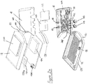
Figure 2a is a detailed exploded schematic drawing of the exemplary height measuring apparatus ofFigures 1a and 1b ; -
Figure 2b is a detailed exploded schematic drawing of an exemplary height measuring apparatus; and -
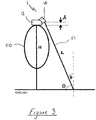
Figure 3 is a schematic cross-sectional illustration showing the principle of operation of a height measuring apparatus in accordance with the present invention. - With reference to
Figures 1a, 1b ,1c, 1d ,1e ,2a and2b , there is shown embodiments of anexemplary measuring apparatus 1 in accordance with the present invention. - The measuring
apparatus 1 provides a means to measure the height of an exemplary object 50 (Figure 3 ) when placed on said object at a position from where the height measurement is to be taken. The measuringapparatus 1 comprises amain body portion 12 and amovable portion 14, wherein themovable portion 14 is movable relative to the main body portion and comprises alaser source 141 and aphoto detector 144. Thephoto detector 144 preferably is a photo diode. - Measuring
apparatus 1 is a slim, portable hand held device that can be stowed in a small space, for example a pocket of a garment or bag. Optionally, the apparatus has a thickness of 20mm or less. - The size constraints imposed upon the measuring apparatus mean that it will not always span across, or project laterally from the point of contact with the object to be measured to an extent that a notional vertical (i.e. perpendicular) line of sight can be established with the ground surface below. Similarly, with certain objects the point of contact from which the height is to be measured may be obscured by other features of that object such that a notional vertical (i.e. perpendicular) line of sight cannot be established with the ground surface below. An example of such an
exemplary subject 50 is shown inFigure 3 where the body of the subject blocks a perpendicular view to the ground below, thereby preventing a substantially vertically directed laser beam from reaching the ground. However, with the present invention, it has been found that a derived measurement of vertical height can be made using a laser beam 51 (Figure 3 ) that is incident at the ground at an angle that is substantially less than 90 degrees. The shape of theexemplary subject 50 shown inFigure 1 is generally representative of a horse or other animal. - With reference to
Figures 2a and2b , themain body 12 and movable 14 portions are each constructed from respective shell halves which define housings which house the necessary hardware, circuitry, processing means and power source for measuringapparatus 1. - As shown in the embodiment of
Figure 2a , themain body portion 12 comprises acircuit board 122,batteries 123, anLCD display 124 and an on/offswitch 125 which activates the apparatus. Thecircuit board 122 supports a processing means (not shown) which runs firmware programmed or adapted to convert the combination of laser path distance (measured by thephoto detector 144 in conjunction with thelaser source 143 as described below) and laser path angle data, together with known constant dimensions of the apparatus, to obtain an accurate measurement of the height of the object being measured. Preferably, the processing means is a microprocessor. The height measurement is displayed on theLCD display 124 for immediate reading by a user. - It will be appreciated that the specific location of the respective circuitry, power supply and processing means is not limited to being in one or other of the
main body 12 andmovable portions 14. For example in the arrangement shown inFigure 2b , thebattery 123 andcircuit board 122 are shown located within themovable portion 14. - In the embodiment shown in
Figures 1a, 1b and2a , the on/offswitch 125 is provided on the main body portion and comprises atrigger mechanism 125a. Thetrigger mechanism 125a can be depressed or activated when the main body portion is placed on the object to be measured. In this way, the trigger mechanism can provide a signal which readies the height measuring apparatus for use. InFigure 2b a furthertransparent cover 1240 is shown placed overdisplay 124. - As shown in
Figures 1a, 1b and2a , thetrigger mechanism 125a may be provided to extend into a space defined by a recessedportion 127 provided on anedge 120 of themain body portion 12. Such arecess 127 enables the measuring apparatus to engage positively with the withers of an animal, for example a horse. - In an alternative arrangement as shown by way of example in
Figure 2b , the on/off switch comprises acapacitive touch switch 125b that is housed within themain body portion 12. - As shown by way of example in
Figure 2b , the measuring apparatus further comprises asocket 128, such as a USB connector, to enable external connection of the apparatus for the purposes or powering, battery recharging, data transfer and the likes. - Referring to
Figures 1a, 1b and2a , the movable portion comprises alaser source 141, such a laser diode, and a photo detector 144 (Fig. 2a ,2b ), the photo detector being located proximate to, and in precise alignment with, thelaser source 141 and adapted to receive reflected laser light from said laser source. A lens 142 (Figure 2 ) andfocus adjuster 143 are also provided for control and adjustment of the beam of laser light emitted from thelaser source 141. Afocus adjuster 145 is provided in conjunction with thephoto detector 144 in order to maximise the amount of reflected laser light that can be captured. Thelaser diode 141 andphoto detector 144 together provide a laser range finder. Preferably, the laser source is a Class 2 laser. - In
Figure 2b , the movable portion is shown having twolaser diodes 141, each with associatedlens 142 andfocus adjuster 143. In this way, one laser diode may be a primary IR laser for the purposes of height measurement and which is invisible to the human eye, while the other laser diode may be a visible laser to create a spot on the ground that is visible to the user of the apparatus. It will be appreciated that while the twolaser diodes 141 of the arrangement inFigure 2b are shown having their own respective lens and focus adjusters, it is possible that the a common lens may be shared. It will be appreciated however that a single, visible, laser (e.g. Class 2 laser) can be employed therefore obviating the requirement for a separate secondary laser diode to provide a visible spot. - In the embodiments as shown in
Figures 1a, 1b ,2a and2b and as described below, themovable portion 14 is slidably connected to themain body portion 12. - With reference to
Figures 2a and2b , at one end of themain body portion 12, the shell halves are each formed having an outwardly curved side that terminates in anupstanding side wall 121. The sidewalls are of a height such that when the shell haves are mated together, the terminal edges of therespective side walls 121 are spaced apart so as to define an elongate slot (121b,Figure 1b ). At one end of themovable portion 14 each shell half is provided a corresponding inwardly curved side that terminates in a side wall having aprojection 146 extending outwardly therefrom, the projection defining agroove 147. Eachgroove 147 is adapted to receive a terminal edge of aside wall 121 ofmain body 14. When the respective shell halves of themovable portion 14 are mated together, therespective projections 146 together define a substantially T-shaped member which engages in use with the elongate slot 121b defined by the respective shell halves of themain body portion 12. Thus when the respective shell halves of themain body 12 andmovable portion 14 are mated together to form the completed measuring apparatus assembly (as shown inFigures 1a, 1b ), themovable portion 14 is engaged with and is slidable relative to themain body portion 12. In this way the connection of the movable portion to the main body portion is a sliding hinge. In this way, thelaser 141 can be oriented at a range of different angles relative themain body portion 12 so that the laser beam can be directed at whatever angle is necessary or appropriate to avoid the body being measured and to obtain a clear line of sight to the ground. Conveniently, the geometry and/or dimensions of the substantially T-shaped member and the elongate slot 121b are such that they mutually frictionally engage in use, such that themovable portion 14 can dwell at any position to which it is moved with respect to themain body portion 12. Advantageously therefore, themovable portion 14 can be maintained (i.e. held in position) at any desired angle with respect to the longitudinal axis A-A (Figure 1 ) of the apparatus. - It will be appreciated that the outwardly curved sides do not necessarily have to comprise the terminal ends of the main body portion as shown in
Figures 1a, 1b , by rather may be hidden from view inboard of the terminal ends of the main body portion. - It will be appreciated that the
movable portion 14 is movable relative to themain body portion 12 such that thelaser 141 andphoto diode 144 may be oriented an any angle between 0° - 89° relative to the longitudinal axis A-A (Figure 1 ) of the measuring apparatus to provide a height measurement. For example, inFigure 1 themovable portion 14 is substantially in alignment with the main body portion 12 (i.e. the hinge is at a "closed" or 0° position). In this orientation, whereby the 141 andphoto diode 144 are aligned substantially perpendicular to the longitudinal axis A-A of the measuring apparatus, a height measurement can be made by placing part or all of themovable potion 14 of measuring apparatus outwardly over an edge of the object to be measured. - In one arrangement as shown by way of example in
Figures 1c and 1d , themoveable portion 14 may be movable to one or more discrete incremental positions with respect to themain body portion 12. These positions are shown by way of example as 12a, 12b, 12c, each position corresponding to a specific pre-set angle of the movable portion with respect to the main body portion. Such positions may be defined by one or more detents or other mechanical stops on the hinge means associated with apparatus. In this way, the angular orientation of themovable portion 14 about the lateral axis B-B of the apparatus can be set at one or more pre-set angles, thereby obviating the need for an accelerometer in said movable portion to measure the angle of said movable portion with respect to the longitudinal axis A-A of the apparatus. This is because the distance between the laser path axis and the main body portion will be a known constant value based on the or each discrete incremental position, thereby enabling height "h" to be calculated using the angular orientation of the laser path axis. In this way, calculation of the height of the object to be measured can be made using data from a tri-axial accelerometer situated in the main body portion of the apparatus only. - As shown in
Figures 2a and2b , adust cover 129 is provided between themain body portion 12 and themovable portion 14. - It will be appreciated that the
movable portion 14 may alternatively be arranged to be pivotally movable with respect to themain body portion 12. For example, themovable portion 14 may be connected to themain body portion 12 by means of a hinge. Similarly, the movable portion may be rotatable with respect to themain body portion 12.Figure 1e shows by way of example how themain body portion 12 may be provided with spaced apartflanges 131 between which the movable portion is pivotally mounted. - Conveniently, a
port 148 provided inmovable portion 14 allows for electrical connection of the powered components of saidmovable portion 14 with the hardware, circuitry, processing means and power source housed within themain body portion 12. - It has been found that even when the
laser beam 51 is incident at the ground surface which supports the object being measured a shallow angle there is still sufficient beam reflected back along the path of incident laser beam for detection by thephoto detector 144. Thus a measurement of straight line beam distance can be made (as indicated by distance "L" inFigure 3 ). - The measurement of distance L is determined by modulating the laser light is amplitude modulated with a high frequency wave (10-20 MHz) and then comparing this modulating waveform with the corresponding waveform obtained from the reflected signal as detected by the
photo detector 144 adjacent to thesource 141 of the laser beam. The beam reflected from the ground will manifest a phase delay compared with the modulating signal as a consequence of the time of flight incurred by the distance travelled by the laser beam along the return journey from the laser beam source to the ground and back. Accordingly, the phase angle or delay between the amplitude waveform of the transmittedbeam 51 and that of the reflected beam is a direct function of the time of flight. Thus measurement of the phase angle indicates the time of flight. As the speed of light is a constant, and as the time of flight is known from the phase angle, the length of the beam path, i.e. distance L, can be calculated. This phase delay is extracted using a conventional heterodyne circuit within the measuring apparatus whereby the high frequency signals are mixed with a common local oscillator signal to obtain two resulting signals that have much lower frequency but the same phase angle as the original pair of signals (modulating and reflected). At this lower frequency this phase angle is determined by a simple microprocessor timer circuit incorporated within the measuring apparatus and/or in communication with the processing means. - In normal circumstances, the fraction of laser light that is reflected back along the beam path (51,
Figure 3 ) is so small it would ordinarily be discarded as worthless and is therefore ignored. However, with the present invention it has been found that the loss in reflected laser light is tolerable such that an accurate distance measurement can be made using the apparatus of the present invention. - By way of example, as described above,
main body portion 12 and themovable portion 14 may each be provided with atri-axial accelerometer 130. The tri-axial accelerometer associated with themain body portion 12 is adapted to measure the angular orientation of saidmain body portion 12 about the vertical (C-C), lateral (B-B) and longitudinal (A-A) in use axes of the apparatus. The tri-axial accelerometer associated with themovable portion 14 is adapted to measure the angular orientation of said movable portion about its vertical, lateral and longitudinal axes. The respectivetri-axial accelerometers 130 are in communication with the processing means. Thus, the position of thelaser 141 and thephoto detector 144 with respect to themain body portion 12 can be accurately determined and the data values relating to spatial location being usable by the processing means in an overall height calculation. In particular, the distance "h" (seeFigure 3 ), which is the vertical offset distance between the origin of the laser beam and the point of contact between themain body portion 12 and the object to measured, is established. In addition, the provision of triaxial inclinometers in themain body portion 12 and/or themovable portion 14 which are in communication with a processing means enables the angle of incidence Φ of the laser to the ground to be automatically measured and the laser path angle θ (theta) to be determined, taking into account any tilt of the apparatus about its axes from the precise horizontal and vertical planes. - The use of tri-axial accelerometers in both the
main body portion 12 and themovable portion 14, or the use of a tri-axial accelerometer in just the main body portion in conjunction with the movable portion being movable to one or more discrete incremental positions with respect to themain body portion 12, means that a user is not required to be meticulous in placing the measuringapparatus 1 in a horizontal orientation on the object to be measured. This is because the triaxial accelerometer(s) and associated processing means can automatically compensate for apparatus orientation in use and relative hinge angle in order to correctly determine the true angle of the laser beam. In addition, they can also determine and make correction for any minor vertical offset of thesource 141 of thelaser beam 51 arising from inclination of the measuring apparatus from an optimum horizontal orientation. - As described above, the processing means, optionally a microprocessor, runs firmware programmed or adapted to convert the combination of laser path distance L, offset height h and laser path angle data θ, together with known constant dimensions of the apparatus to obtain an accurate measurement of the vertical height H of the object being measured. The calculation for vertical height is performed by the processing means based on established trigonometric formulae, for example the formula

- The resultant height measurement is displayed on the
LCD 124 for immediate reading by a user. Conveniently, the calculated vertical height can be displayed in appropriate units selected by the user and chosen from a menu stored on the processing means. - With reference to
Figure 2b , an example of a mode of use of the apparatus comprises the following steps: - a) holding the apparatus by gripping the
main body portion 12; - b) tapping and holding the area on the
main body portion 12 which is proximate thecapacitive touch switch 125b to activate the apparatus; - c) after a delay of approximately two seconds the
display 124 activates and pressure on thecapacitive touch switch 125b can be released; - d) placing an
edge 120 of themain body portion 120 of the apparatus onto an upper surface of the object to be measured, the apparatus being held in an approximately level orientation; - e) tapping the
main body portion 12 proximate thecapacitive touch switch 125b to activate measurement mode; - f) adjusting the
movable portion 14 so that the laser establishes a line of sight to the ground; - g) tapping the
main body portion 12 proximate thecapacitive touch switch 125b in order to freeze the displayed height measurement; - h) if necessary, tapping
main body portion 12 proximate thecapacitive touch switch 125b again to reactivate measurement mode; - i) tapping and holding the
main body portion 12 proximate thecapacitive touch switch 125b to turn off the apparatus; or alternatively - k) leaving the apparatus for approximately 30 seconds for automatic switch off.
- As the operation of the measuring apparatus is instantaneous and silent, it is particularly suited for use in the measurement of horses. This is because horses generally do not stand still for sufficiently long periods to make accurate measurements using traditional techniques and because they are easily unsettled by unfamiliar noises in close proximity. It will be appreciated, however, that a height measuring apparatus in accordance with the present invention is not limited to use with animals, but rather is suitable for use with anything which the apparatus can be placed in contact.
- Conveniently, the measuring apparatus optionally includes the following beneficial features:
- Date and time stamping of measurements made
- Photo, video and/or audio recording means
- Scanning and reading RFID or other chip-based technologies
- Wireless communication with remote server
- Interfacing with "smart" devices and applications ("apps") running on said devices
- Means to sense vital signs and/or take appropriate biometric measurements
- Ability to receive or upload pre-prepared data sets (e.g. lists of people, patients, animals etc.)
- The ability to measure other physical dimensions and parameters of physical space.
- While the embodiments of the invention have been described as being slim and pocket-sized, it would be understood that the size of the measuring apparatus is not limited. For example, where heights to be measured are substantially greater than that of a human or animal, more powerful laser diodes, photo detectors and batteries etc. may be required and so the apparatus may require accordingly increased dimensions. In other words, it will be appreciated that height measuring apparatuses in accordance with the present invention may be particularly optimized for measurement of specific height ranges that are appropriate to particular groups of subjects that are most commonly measured by specific user groups.
- It will be understood from the foregoing description that the apparatus in accordance with the invention provides a number of distinct advantages, which include the ability to use a laser beam that can be inclined at an angle from the horizontal and shone at the ground with no aiming mechanism and no requirement to aim at any particular reference point or target on the ground. In this way the need for accurate aiming mechanisms, eye pieces, tripods and specific specialised training etc. is obviated. Furthermore, through the provision of a movable portion, the angle of the laser beam can be configured at an optimum angle to suit a shoulder of an object being measured. Still furthermore, the use of a plurality of tri-axial accelerometers provides automatic compensation for any angle of apparatus orientation in use and thereby obviates any requirement for a user to be exact in how the apparatus is placed on the object being measured. Thus minimum user skill is required.
Claims (15)
- A height measuring apparatus (1) comprising a main body portion (12) adapted for placement upon an object to be measured, and a movable portion (14) which is connected and movable relative to the main body portion (12), wherein the movable portion (14) comprises a laser source (141) and a photo detector (144), the movable portion (14) being movable so that the laser source (141) can be orientated at a range of different angles relative to the main body portion (12) and that a laser beam (51) from the laser source (141) can be directed to the ground when the main body portion (12) is placed on the object to be measured, characterised in that the main body portion (12) is provided with at least one tri-axial accelerometer (130) being configured to measure the angular orientation of the main body portion.
- A height measuring apparatus as claimed in claim 1, wherein the movable portion is provided with at least one tri-axial accelerometer, the tri-axial accelerometer being configured to measure the angular orientation of the movable portion with respect to the main body portion.
- A height measuring apparatus as claimed in claim 1 or in claim 2, wherein the laser source, the photo detector and the tri-axial accelerometer(s) are in communication with a processor, the processor being configured to determine the angle of incidence of the laser beam to the ground, and to determine the vertical offset distance between the laser source and the point of contact of the main body portion with the object being measured.
- A height measuring apparatus as claimed in claim 3, wherein the laser beam is frequency modulated, and wherein the processor is configured to measure the phase angle or phase delay between the amplitude waveform of laser beam transmitted from the laser source and that of the reflected beam from the ground to the photo detector.
- A height measuring apparatus as claimed in claim 4, wherein the processor runs firmware programmed or adapted to convert a combination of the phase angle or phase delay, the angle of incidence of the laser beam to the ground, and the vertical offset distance between the laser source and the point of contact of the main body portion with the object being measured, into a measurement of the height of the object being measured.
- A height measuring apparatus as claimed in any preceding claim, wherein the movable portion is connected by a hinge to the main body portion.
- A height measuring apparatus as claimed in claim 6, wherein the movable portion and the main body portion are each constructed from respective shell halves, which define housings that house the laser source, the photo detector, the tri-axial accelerometer(s), the processor, a battery power source, a display and an on/off switch of the height measuring apparatus.
- A height measuring apparatus as claimed in claim 7, wherein the shell halves of the main body portion are each formed having an outwardly curved side that terminates in an upstanding side wall, wherein the sidewalls are of a height such that when the main body portion shell haves are mated together, the terminal edges of the respective side walls are spaced apart so as to define an elongate slot,and wherein the shell halves of the movable portion are each formed having a inwardly curved side that terminates in a side wall having a projection extending outwardly therefrom, whereby the respective projections define a T-shaped member when the movable portion shell haves are mated together,and wherein the T-shaped member of the movable portion is adapted to slidably engage with the corresponding elongate slot of the main body portion.
- A height measuring apparatus as claimed in claim 8, wherein the slidable engagement of the T-shaped member of the movable portion and the elongate slot of the main body portion is a frictional sliding engagement so that the laser source and the photo detector on the movable portion can be oriented and maintained at an angle between 0° - 89° relative to a longitudinal axis of the main body portion.
- A height measuring apparatus as claimed in any preceding claim, wherein the moveable portion is movable to one or more discrete incremental positions with respect to the main body portion.
- A height measuring apparatus as claimed in any preceding claim, wherein the laser source is a laser diode and the photo detector is a photo diode, wherein the laser diode and the photo diode are each provided with a focus adjuster.
- A height measuring apparatus as claimed in any preceding claim, wherein the apparatus further comprises photo, and/or video and/or audio recording means.
- A height measuring apparatus as claimed in any preceding claim, wherein the apparatus further comprises an RFID reader.
- A height measuring apparatus as claimed in any preceding claim, wherein the apparatus further comprises wireless communication means.
- Use of the apparatus as claimed in any preceding claim to obtain a measurement of height of an object.
Applications Claiming Priority (3)
| Application Number | Priority Date | Filing Date | Title |
|---|---|---|---|
| GB1416023.8A GB2530053A (en) | 2014-09-10 | 2014-09-10 | Measuring device |
| US14/618,428 US20160069678A1 (en) | 2014-09-10 | 2015-02-10 | Measuring Apparatus |
| PCT/GB2015/052602 WO2016038361A1 (en) | 2014-09-10 | 2015-09-09 | Measuring apparatus |
Publications (2)
| Publication Number | Publication Date |
|---|---|
| EP3191792A1 EP3191792A1 (en) | 2017-07-19 |
| EP3191792B1 true EP3191792B1 (en) | 2021-12-08 |
Family
ID=51796495
Family Applications (1)
| Application Number | Title | Priority Date | Filing Date |
|---|---|---|---|
| EP15766201.6A Not-in-force EP3191792B1 (en) | 2014-09-10 | 2015-09-09 | Measuring apparatus |
Country Status (9)
| Country | Link |
|---|---|
| US (2) | US20160069678A1 (en) |
| EP (1) | EP3191792B1 (en) |
| JP (1) | JP2017528736A (en) |
| CN (1) | CN107072542A (en) |
| AU (1) | AU2015313979A1 (en) |
| CA (1) | CA2960911A1 (en) |
| GB (1) | GB2530053A (en) |
| RU (1) | RU2017111474A (en) |
| WO (1) | WO2016038361A1 (en) |
Families Citing this family (12)
| Publication number | Priority date | Publication date | Assignee | Title |
|---|---|---|---|---|
| USD681015S1 (en) | 2012-09-08 | 2013-04-30 | Apple Inc. | Earphone |
| CN105832340A (en) * | 2016-05-12 | 2016-08-10 | 董元忠 | Intelligent multifunctional handheld laser height measuring instrument |
| DE102017205195A1 (en) * | 2016-07-28 | 2018-02-01 | Robert Bosch Gmbh | Laser distance measuring device |
| USD801314S1 (en) | 2016-09-06 | 2017-10-31 | Apple Inc. | Pair of earphones |
| DE102016225275A1 (en) * | 2016-12-16 | 2018-06-21 | Robert Bosch Gmbh | Method for operating a laser rangefinder |
| CN108007289A (en) * | 2017-12-06 | 2018-05-08 | 北京小米移动软件有限公司 | The measuring method and device of Intelligent measuring tape |
| DE102018133045B3 (en) * | 2018-12-20 | 2020-02-13 | Sascha Droste | Measuring system for measuring clothing |
| CN110220460B (en) * | 2019-06-25 | 2024-03-19 | 中交一公局第四工程有限公司 | A tunnel safety step distance monitoring and measuring device |
| US11486992B2 (en) | 2019-11-15 | 2022-11-01 | Stage Lighting Patents, LLC | Rotating range sensor to measure truss vertical height for stage configurations |
| US11549810B2 (en) * | 2020-12-18 | 2023-01-10 | Robyn Holloway | Laser level device |
| CN113142092A (en) * | 2021-04-23 | 2021-07-23 | 青海净意信息科技有限公司 | Portable livestock laser weight measuring device |
| KR20230093995A (en) * | 2021-12-20 | 2023-06-27 | 주식회사 맥파이테크 | A height measuring device and a height measuring method |
Family Cites Families (15)
| Publication number | Priority date | Publication date | Assignee | Title |
|---|---|---|---|---|
| EP2275775B1 (en) * | 2002-01-16 | 2015-09-23 | Faro Technologies, Inc. | Laser-based coordinate measuring device and laser-based method for measuring coordinates |
| US7200952B2 (en) | 2004-01-20 | 2007-04-10 | Tanita Corporation | Bioinstrumentation apparatus with height measuring device |
| EP1782097A1 (en) * | 2004-07-21 | 2007-05-09 | I-Concepts & Marketing Sarl | Combination tool for aligning, measuring distances and sensing objects under a surface |
| WO2008077307A1 (en) * | 2006-12-22 | 2008-07-03 | Zhongshan Transtek Electronics Co., Ltd | Stature measuring device |
| DE102007038528A1 (en) * | 2007-08-16 | 2009-02-19 | Robert Bosch Gmbh | Laser rangefinders |
| KR20090002046U (en) * | 2007-08-28 | 2009-03-04 | 삼서건설 주식회사 | Manhole maintenance height measuring device |
| KR100929237B1 (en) * | 2009-04-08 | 2009-11-30 | (주)태성로직스 | Stack height measuring device |
| CN201628771U (en) * | 2010-03-29 | 2010-11-10 | 中冶建工有限公司 | Digital laser range finder |
| GB2481199B (en) * | 2010-06-14 | 2015-01-21 | Pet Technology Store Ltd | A measuring system |
| EP2710536A4 (en) * | 2011-05-11 | 2015-07-22 | Proiam Llc | Enrollment apparatus, system, and method featuring three dimensional camera |
| CN102871664B (en) * | 2011-07-12 | 2015-10-21 | (株)拜斯倍斯 | Height relevant information determinator and Body composition analysis device |
| CN102506719B (en) * | 2011-11-01 | 2014-07-23 | 浙江大学 | Height gauge for measuring height of trees |
| KR20120131132A (en) * | 2012-10-22 | 2012-12-04 | 김성희 | Level measuring equipment of excavator |
| CN103499334B (en) * | 2013-09-05 | 2016-08-17 | 小米科技有限责任公司 | Distance measurement method, device and electronic equipment |
| GB2519627A (en) | 2013-10-28 | 2015-04-29 | Chia Hsin Liu | Height measurement device |
-
2014
- 2014-09-10 GB GB1416023.8A patent/GB2530053A/en not_active Withdrawn
-
2015
- 2015-02-10 US US14/618,428 patent/US20160069678A1/en not_active Abandoned
- 2015-09-09 US US15/510,262 patent/US10996047B2/en not_active Expired - Fee Related
- 2015-09-09 JP JP2017534013A patent/JP2017528736A/en active Pending
- 2015-09-09 AU AU2015313979A patent/AU2015313979A1/en not_active Abandoned
- 2015-09-09 CN CN201580056365.9A patent/CN107072542A/en active Pending
- 2015-09-09 RU RU2017111474A patent/RU2017111474A/en not_active Application Discontinuation
- 2015-09-09 EP EP15766201.6A patent/EP3191792B1/en not_active Not-in-force
- 2015-09-09 WO PCT/GB2015/052602 patent/WO2016038361A1/en not_active Ceased
- 2015-09-09 CA CA2960911A patent/CA2960911A1/en not_active Abandoned
Non-Patent Citations (1)
| Title |
|---|
| None * |
Also Published As
| Publication number | Publication date |
|---|---|
| AU2015313979A1 (en) | 2017-04-27 |
| GB201416023D0 (en) | 2014-10-22 |
| US20160069678A1 (en) | 2016-03-10 |
| US20170241770A1 (en) | 2017-08-24 |
| JP2017528736A (en) | 2017-09-28 |
| CN107072542A (en) | 2017-08-18 |
| GB2530053A (en) | 2016-03-16 |
| WO2016038361A1 (en) | 2016-03-17 |
| RU2017111474A (en) | 2018-10-11 |
| CA2960911A1 (en) | 2016-03-17 |
| EP3191792A1 (en) | 2017-07-19 |
| US10996047B2 (en) | 2021-05-04 |
Similar Documents
| Publication | Publication Date | Title |
|---|---|---|
| US10996047B2 (en) | Measuring appartus | |
| CN104508425B (en) | Hand-held distance-measuring device with angle determination unit | |
| CN103983255B (en) | Moving field controller for measurement and remotely control | |
| US9816813B2 (en) | Handheld measuring aid for use with a six-degrees-of-freedom laser tracker | |
| US11692811B2 (en) | System and method of defining a path and scanning an environment | |
| CN104024797B (en) | Method and device for determining 3D coordinates of an object | |
| US9603552B2 (en) | Measuring method, pedestal and measuring system for determining biometric data of human feet | |
| US20100088914A1 (en) | Train Rail Alignment and Distance System | |
| CN104011502B (en) | Automatically the measurement of the level | |
| US20130271744A1 (en) | Laser rangefinder module for operative association with smartphones and tablet computers | |
| US20220406005A1 (en) | Targetless tracking of measurement device during capture of surrounding data | |
| KR20210033076A (en) | System for measuring growth state of child using smart scale | |
| KR20190011163A (en) | Apparatus and method for measuring blood pressure | |
| CN109154417B (en) | Improved handheld system for three-dimensional scanning with smart phone | |
| KR101934010B1 (en) | Distance measuring apparatus | |
| US12130154B2 (en) | Automatic electronic rangefinder | |
| US10261185B2 (en) | System and method for remotely measuring distances between two points | |
| US20160341546A1 (en) | System and Method for Determination of Distance Between Two Points in 3-Dimensional Space | |
| KR102392096B1 (en) | Automatic electronic rangefinder | |
| US12254642B2 (en) | Automatic registration of multiple measurement devices | |
| GB2481199A (en) | An animal measuring system | |
| US20260034414A1 (en) | Golf distance measuring device | |
| KR20150121284A (en) | Apparatus for measuring distance and azimuth with removable structure to glasses |
Legal Events
| Date | Code | Title | Description |
|---|---|---|---|
| STAA | Information on the status of an ep patent application or granted ep patent |
Free format text: STATUS: THE INTERNATIONAL PUBLICATION HAS BEEN MADE |
|
| PUAI | Public reference made under article 153(3) epc to a published international application that has entered the european phase |
Free format text: ORIGINAL CODE: 0009012 |
|
| STAA | Information on the status of an ep patent application or granted ep patent |
Free format text: STATUS: REQUEST FOR EXAMINATION WAS MADE |
|
| 17P | Request for examination filed |
Effective date: 20170405 |
|
| AK | Designated contracting states |
Kind code of ref document: A1 Designated state(s): AL AT BE BG CH CY CZ DE DK EE ES FI FR GB GR HR HU IE IS IT LI LT LU LV MC MK MT NL NO PL PT RO RS SE SI SK SM TR |
|
| AX | Request for extension of the european patent |
Extension state: BA ME |
|
| DAV | Request for validation of the european patent (deleted) | ||
| DAX | Request for extension of the european patent (deleted) | ||
| GRAP | Despatch of communication of intention to grant a patent |
Free format text: ORIGINAL CODE: EPIDOSNIGR1 |
|
| STAA | Information on the status of an ep patent application or granted ep patent |
Free format text: STATUS: GRANT OF PATENT IS INTENDED |
|
| INTG | Intention to grant announced |
Effective date: 20201106 |
|
| GRAJ | Information related to disapproval of communication of intention to grant by the applicant or resumption of examination proceedings by the epo deleted |
Free format text: ORIGINAL CODE: EPIDOSDIGR1 |
|
| STAA | Information on the status of an ep patent application or granted ep patent |
Free format text: STATUS: REQUEST FOR EXAMINATION WAS MADE |
|
| GRAP | Despatch of communication of intention to grant a patent |
Free format text: ORIGINAL CODE: EPIDOSNIGR1 |
|
| INTC | Intention to grant announced (deleted) | ||
| STAA | Information on the status of an ep patent application or granted ep patent |
Free format text: STATUS: GRANT OF PATENT IS INTENDED |
|
| INTG | Intention to grant announced |
Effective date: 20210506 |
|
| GRAJ | Information related to disapproval of communication of intention to grant by the applicant or resumption of examination proceedings by the epo deleted |
Free format text: ORIGINAL CODE: EPIDOSDIGR1 |
|
| STAA | Information on the status of an ep patent application or granted ep patent |
Free format text: STATUS: REQUEST FOR EXAMINATION WAS MADE |
|
| INTC | Intention to grant announced (deleted) | ||
| GRAP | Despatch of communication of intention to grant a patent |
Free format text: ORIGINAL CODE: EPIDOSNIGR1 |
|
| STAA | Information on the status of an ep patent application or granted ep patent |
Free format text: STATUS: GRANT OF PATENT IS INTENDED |
|
| GRAS | Grant fee paid |
Free format text: ORIGINAL CODE: EPIDOSNIGR3 |
|
| GRAA | (expected) grant |
Free format text: ORIGINAL CODE: 0009210 |
|
| STAA | Information on the status of an ep patent application or granted ep patent |
Free format text: STATUS: THE PATENT HAS BEEN GRANTED |
|
| INTG | Intention to grant announced |
Effective date: 20211014 |
|
| AK | Designated contracting states |
Kind code of ref document: B1 Designated state(s): AL AT BE BG CH CY CZ DE DK EE ES FI FR GB GR HR HU IE IS IT LI LT LU LV MC MK MT NL NO PL PT RO RS SE SI SK SM TR |
|
| RAP3 | Party data changed (applicant data changed or rights of an application transferred) |
Owner name: CAPALTEC LIMITED |
|
| REG | Reference to a national code |
Ref country code: GB Ref legal event code: FG4D |
|
| REG | Reference to a national code |
Ref country code: AT Ref legal event code: REF Ref document number: 1454097 Country of ref document: AT Kind code of ref document: T Effective date: 20211215 Ref country code: CH Ref legal event code: EP |
|
| REG | Reference to a national code |
Ref country code: DE Ref legal event code: R096 Ref document number: 602015075618 Country of ref document: DE |
|
| REG | Reference to a national code |
Ref country code: IE Ref legal event code: FG4D |
|
| REG | Reference to a national code |
Ref country code: LT Ref legal event code: MG9D |
|
| REG | Reference to a national code |
Ref country code: NL Ref legal event code: MP Effective date: 20211208 |
|
| PG25 | Lapsed in a contracting state [announced via postgrant information from national office to epo] |
Ref country code: RS Free format text: LAPSE BECAUSE OF FAILURE TO SUBMIT A TRANSLATION OF THE DESCRIPTION OR TO PAY THE FEE WITHIN THE PRESCRIBED TIME-LIMIT Effective date: 20211208 Ref country code: LT Free format text: LAPSE BECAUSE OF FAILURE TO SUBMIT A TRANSLATION OF THE DESCRIPTION OR TO PAY THE FEE WITHIN THE PRESCRIBED TIME-LIMIT Effective date: 20211208 Ref country code: FI Free format text: LAPSE BECAUSE OF FAILURE TO SUBMIT A TRANSLATION OF THE DESCRIPTION OR TO PAY THE FEE WITHIN THE PRESCRIBED TIME-LIMIT Effective date: 20211208 Ref country code: BG Free format text: LAPSE BECAUSE OF FAILURE TO SUBMIT A TRANSLATION OF THE DESCRIPTION OR TO PAY THE FEE WITHIN THE PRESCRIBED TIME-LIMIT Effective date: 20220308 |
|
| REG | Reference to a national code |
Ref country code: AT Ref legal event code: MK05 Ref document number: 1454097 Country of ref document: AT Kind code of ref document: T Effective date: 20211208 |
|
| PG25 | Lapsed in a contracting state [announced via postgrant information from national office to epo] |
Ref country code: SE Free format text: LAPSE BECAUSE OF FAILURE TO SUBMIT A TRANSLATION OF THE DESCRIPTION OR TO PAY THE FEE WITHIN THE PRESCRIBED TIME-LIMIT Effective date: 20211208 Ref country code: NO Free format text: LAPSE BECAUSE OF FAILURE TO SUBMIT A TRANSLATION OF THE DESCRIPTION OR TO PAY THE FEE WITHIN THE PRESCRIBED TIME-LIMIT Effective date: 20220308 Ref country code: LV Free format text: LAPSE BECAUSE OF FAILURE TO SUBMIT A TRANSLATION OF THE DESCRIPTION OR TO PAY THE FEE WITHIN THE PRESCRIBED TIME-LIMIT Effective date: 20211208 Ref country code: HR Free format text: LAPSE BECAUSE OF FAILURE TO SUBMIT A TRANSLATION OF THE DESCRIPTION OR TO PAY THE FEE WITHIN THE PRESCRIBED TIME-LIMIT Effective date: 20211208 Ref country code: GR Free format text: LAPSE BECAUSE OF FAILURE TO SUBMIT A TRANSLATION OF THE DESCRIPTION OR TO PAY THE FEE WITHIN THE PRESCRIBED TIME-LIMIT Effective date: 20220309 Ref country code: ES Free format text: LAPSE BECAUSE OF FAILURE TO SUBMIT A TRANSLATION OF THE DESCRIPTION OR TO PAY THE FEE WITHIN THE PRESCRIBED TIME-LIMIT Effective date: 20211208 |
|
| PG25 | Lapsed in a contracting state [announced via postgrant information from national office to epo] |
Ref country code: NL Free format text: LAPSE BECAUSE OF FAILURE TO SUBMIT A TRANSLATION OF THE DESCRIPTION OR TO PAY THE FEE WITHIN THE PRESCRIBED TIME-LIMIT Effective date: 20211208 |
|
| PG25 | Lapsed in a contracting state [announced via postgrant information from national office to epo] |
Ref country code: SM Free format text: LAPSE BECAUSE OF FAILURE TO SUBMIT A TRANSLATION OF THE DESCRIPTION OR TO PAY THE FEE WITHIN THE PRESCRIBED TIME-LIMIT Effective date: 20211208 Ref country code: SK Free format text: LAPSE BECAUSE OF FAILURE TO SUBMIT A TRANSLATION OF THE DESCRIPTION OR TO PAY THE FEE WITHIN THE PRESCRIBED TIME-LIMIT Effective date: 20211208 Ref country code: RO Free format text: LAPSE BECAUSE OF FAILURE TO SUBMIT A TRANSLATION OF THE DESCRIPTION OR TO PAY THE FEE WITHIN THE PRESCRIBED TIME-LIMIT Effective date: 20211208 Ref country code: PT Free format text: LAPSE BECAUSE OF FAILURE TO SUBMIT A TRANSLATION OF THE DESCRIPTION OR TO PAY THE FEE WITHIN THE PRESCRIBED TIME-LIMIT Effective date: 20220408 Ref country code: EE Free format text: LAPSE BECAUSE OF FAILURE TO SUBMIT A TRANSLATION OF THE DESCRIPTION OR TO PAY THE FEE WITHIN THE PRESCRIBED TIME-LIMIT Effective date: 20211208 Ref country code: CZ Free format text: LAPSE BECAUSE OF FAILURE TO SUBMIT A TRANSLATION OF THE DESCRIPTION OR TO PAY THE FEE WITHIN THE PRESCRIBED TIME-LIMIT Effective date: 20211208 |
|
| PG25 | Lapsed in a contracting state [announced via postgrant information from national office to epo] |
Ref country code: PL Free format text: LAPSE BECAUSE OF FAILURE TO SUBMIT A TRANSLATION OF THE DESCRIPTION OR TO PAY THE FEE WITHIN THE PRESCRIBED TIME-LIMIT Effective date: 20211208 Ref country code: AT Free format text: LAPSE BECAUSE OF FAILURE TO SUBMIT A TRANSLATION OF THE DESCRIPTION OR TO PAY THE FEE WITHIN THE PRESCRIBED TIME-LIMIT Effective date: 20211208 |
|
| REG | Reference to a national code |
Ref country code: DE Ref legal event code: R097 Ref document number: 602015075618 Country of ref document: DE |
|
| PG25 | Lapsed in a contracting state [announced via postgrant information from national office to epo] |
Ref country code: IS Free format text: LAPSE BECAUSE OF FAILURE TO SUBMIT A TRANSLATION OF THE DESCRIPTION OR TO PAY THE FEE WITHIN THE PRESCRIBED TIME-LIMIT Effective date: 20220408 |
|
| PLBE | No opposition filed within time limit |
Free format text: ORIGINAL CODE: 0009261 |
|
| STAA | Information on the status of an ep patent application or granted ep patent |
Free format text: STATUS: NO OPPOSITION FILED WITHIN TIME LIMIT |
|
| PG25 | Lapsed in a contracting state [announced via postgrant information from national office to epo] |
Ref country code: DK Free format text: LAPSE BECAUSE OF FAILURE TO SUBMIT A TRANSLATION OF THE DESCRIPTION OR TO PAY THE FEE WITHIN THE PRESCRIBED TIME-LIMIT Effective date: 20211208 Ref country code: AL Free format text: LAPSE BECAUSE OF FAILURE TO SUBMIT A TRANSLATION OF THE DESCRIPTION OR TO PAY THE FEE WITHIN THE PRESCRIBED TIME-LIMIT Effective date: 20211208 |
|
| 26N | No opposition filed |
Effective date: 20220909 |
|
| PG25 | Lapsed in a contracting state [announced via postgrant information from national office to epo] |
Ref country code: SI Free format text: LAPSE BECAUSE OF FAILURE TO SUBMIT A TRANSLATION OF THE DESCRIPTION OR TO PAY THE FEE WITHIN THE PRESCRIBED TIME-LIMIT Effective date: 20211208 |
|
| REG | Reference to a national code |
Ref country code: DE Ref legal event code: R119 Ref document number: 602015075618 Country of ref document: DE |
|
| PG25 | Lapsed in a contracting state [announced via postgrant information from national office to epo] |
Ref country code: MC Free format text: LAPSE BECAUSE OF FAILURE TO SUBMIT A TRANSLATION OF THE DESCRIPTION OR TO PAY THE FEE WITHIN THE PRESCRIBED TIME-LIMIT Effective date: 20211208 |
|
| REG | Reference to a national code |
Ref country code: CH Ref legal event code: PL |
|
| REG | Reference to a national code |
Ref country code: BE Ref legal event code: MM Effective date: 20220930 |
|
| PG25 | Lapsed in a contracting state [announced via postgrant information from national office to epo] |
Ref country code: IT Free format text: LAPSE BECAUSE OF FAILURE TO SUBMIT A TRANSLATION OF THE DESCRIPTION OR TO PAY THE FEE WITHIN THE PRESCRIBED TIME-LIMIT Effective date: 20211208 |
|
| PGFP | Annual fee paid to national office [announced via postgrant information from national office to epo] |
Ref country code: GB Payment date: 20230331 Year of fee payment: 8 |
|
| PG25 | Lapsed in a contracting state [announced via postgrant information from national office to epo] |
Ref country code: LU Free format text: LAPSE BECAUSE OF NON-PAYMENT OF DUE FEES Effective date: 20220909 |
|
| PG25 | Lapsed in a contracting state [announced via postgrant information from national office to epo] |
Ref country code: LI Free format text: LAPSE BECAUSE OF NON-PAYMENT OF DUE FEES Effective date: 20220930 Ref country code: IE Free format text: LAPSE BECAUSE OF NON-PAYMENT OF DUE FEES Effective date: 20220909 Ref country code: FR Free format text: LAPSE BECAUSE OF NON-PAYMENT OF DUE FEES Effective date: 20220930 Ref country code: DE Free format text: LAPSE BECAUSE OF NON-PAYMENT OF DUE FEES Effective date: 20230401 Ref country code: CH Free format text: LAPSE BECAUSE OF NON-PAYMENT OF DUE FEES Effective date: 20220930 |
|
| PG25 | Lapsed in a contracting state [announced via postgrant information from national office to epo] |
Ref country code: BE Free format text: LAPSE BECAUSE OF NON-PAYMENT OF DUE FEES Effective date: 20220930 |
|
| PG25 | Lapsed in a contracting state [announced via postgrant information from national office to epo] |
Ref country code: HU Free format text: LAPSE BECAUSE OF FAILURE TO SUBMIT A TRANSLATION OF THE DESCRIPTION OR TO PAY THE FEE WITHIN THE PRESCRIBED TIME-LIMIT; INVALID AB INITIO Effective date: 20150909 |
|
| PG25 | Lapsed in a contracting state [announced via postgrant information from national office to epo] |
Ref country code: CY Free format text: LAPSE BECAUSE OF FAILURE TO SUBMIT A TRANSLATION OF THE DESCRIPTION OR TO PAY THE FEE WITHIN THE PRESCRIBED TIME-LIMIT Effective date: 20211208 |
|
| GBPC | Gb: european patent ceased through non-payment of renewal fee |
Effective date: 20230909 |
|
| PG25 | Lapsed in a contracting state [announced via postgrant information from national office to epo] |
Ref country code: MK Free format text: LAPSE BECAUSE OF FAILURE TO SUBMIT A TRANSLATION OF THE DESCRIPTION OR TO PAY THE FEE WITHIN THE PRESCRIBED TIME-LIMIT Effective date: 20211208 |
|
| PG25 | Lapsed in a contracting state [announced via postgrant information from national office to epo] |
Ref country code: TR Free format text: LAPSE BECAUSE OF FAILURE TO SUBMIT A TRANSLATION OF THE DESCRIPTION OR TO PAY THE FEE WITHIN THE PRESCRIBED TIME-LIMIT Effective date: 20211208 |
|
| PG25 | Lapsed in a contracting state [announced via postgrant information from national office to epo] |
Ref country code: GB Free format text: LAPSE BECAUSE OF NON-PAYMENT OF DUE FEES Effective date: 20230909 |
|
| PG25 | Lapsed in a contracting state [announced via postgrant information from national office to epo] |
Ref country code: GB Free format text: LAPSE BECAUSE OF NON-PAYMENT OF DUE FEES Effective date: 20230909 |
|
| PG25 | Lapsed in a contracting state [announced via postgrant information from national office to epo] |
Ref country code: MT Free format text: LAPSE BECAUSE OF FAILURE TO SUBMIT A TRANSLATION OF THE DESCRIPTION OR TO PAY THE FEE WITHIN THE PRESCRIBED TIME-LIMIT Effective date: 20211208 |