EP3191718B1 - A clip - Google Patents
A clip Download PDFInfo
- Publication number
- EP3191718B1 EP3191718B1 EP15771228.2A EP15771228A EP3191718B1 EP 3191718 B1 EP3191718 B1 EP 3191718B1 EP 15771228 A EP15771228 A EP 15771228A EP 3191718 B1 EP3191718 B1 EP 3191718B1
- Authority
- EP
- European Patent Office
- Prior art keywords
- clip
- lug
- halves
- gripping
- retainer
- Prior art date
- Legal status (The legal status is an assumption and is not a legal conclusion. Google has not performed a legal analysis and makes no representation as to the accuracy of the status listed.)
- Active
Links
Images






Classifications
-
- A—HUMAN NECESSITIES
- A47—FURNITURE; DOMESTIC ARTICLES OR APPLIANCES; COFFEE MILLS; SPICE MILLS; SUCTION CLEANERS IN GENERAL
- A47G—HOUSEHOLD OR TABLE EQUIPMENT
- A47G25/00—Household implements used in connection with wearing apparel; Dress, hat or umbrella holders
- A47G25/14—Clothing hangers, e.g. suit hangers
- A47G25/48—Hangers with clamps or the like, e.g. for trousers or skirts
- A47G25/483—Hangers with clamps or the like, e.g. for trousers or skirts with pivoting clamps or clips having axis of rotation parallel with the hanger arms
-
- F—MECHANICAL ENGINEERING; LIGHTING; HEATING; WEAPONS; BLASTING
- F16—ENGINEERING ELEMENTS AND UNITS; GENERAL MEASURES FOR PRODUCING AND MAINTAINING EFFECTIVE FUNCTIONING OF MACHINES OR INSTALLATIONS; THERMAL INSULATION IN GENERAL
- F16B—DEVICES FOR FASTENING OR SECURING CONSTRUCTIONAL ELEMENTS OR MACHINE PARTS TOGETHER, e.g. NAILS, BOLTS, CIRCLIPS, CLAMPS, CLIPS OR WEDGES; JOINTS OR JOINTING
- F16B2/00—Friction-grip releasable fastenings
- F16B2/02—Clamps, i.e. with gripping action effected by positive means other than the inherent resistance to deformation of the material of the fastening
- F16B2/06—Clamps, i.e. with gripping action effected by positive means other than the inherent resistance to deformation of the material of the fastening external, i.e. with contracting action
- F16B2/10—Clamps, i.e. with gripping action effected by positive means other than the inherent resistance to deformation of the material of the fastening external, i.e. with contracting action using pivoting jaws
-
- A—HUMAN NECESSITIES
- A47—FURNITURE; DOMESTIC ARTICLES OR APPLIANCES; COFFEE MILLS; SPICE MILLS; SUCTION CLEANERS IN GENERAL
- A47G—HOUSEHOLD OR TABLE EQUIPMENT
- A47G25/00—Household implements used in connection with wearing apparel; Dress, hat or umbrella holders
-
- A—HUMAN NECESSITIES
- A47—FURNITURE; DOMESTIC ARTICLES OR APPLIANCES; COFFEE MILLS; SPICE MILLS; SUCTION CLEANERS IN GENERAL
- A47G—HOUSEHOLD OR TABLE EQUIPMENT
- A47G25/00—Household implements used in connection with wearing apparel; Dress, hat or umbrella holders
- A47G25/005—Shoe hangers
-
- D—TEXTILES; PAPER
- D06—TREATMENT OF TEXTILES OR THE LIKE; LAUNDERING; FLEXIBLE MATERIALS NOT OTHERWISE PROVIDED FOR
- D06F—LAUNDERING, DRYING, IRONING, PRESSING OR FOLDING TEXTILE ARTICLES
- D06F55/00—Clothes-pegs
- D06F55/02—Clothes-pegs with pivoted independent clamping members
-
- F—MECHANICAL ENGINEERING; LIGHTING; HEATING; WEAPONS; BLASTING
- F16—ENGINEERING ELEMENTS AND UNITS; GENERAL MEASURES FOR PRODUCING AND MAINTAINING EFFECTIVE FUNCTIONING OF MACHINES OR INSTALLATIONS; THERMAL INSULATION IN GENERAL
- F16B—DEVICES FOR FASTENING OR SECURING CONSTRUCTIONAL ELEMENTS OR MACHINE PARTS TOGETHER, e.g. NAILS, BOLTS, CIRCLIPS, CLAMPS, CLIPS OR WEDGES; JOINTS OR JOINTING
- F16B2/00—Friction-grip releasable fastenings
- F16B2/005—Means to increase the friction-coefficient
-
- F—MECHANICAL ENGINEERING; LIGHTING; HEATING; WEAPONS; BLASTING
- F16—ENGINEERING ELEMENTS AND UNITS; GENERAL MEASURES FOR PRODUCING AND MAINTAINING EFFECTIVE FUNCTIONING OF MACHINES OR INSTALLATIONS; THERMAL INSULATION IN GENERAL
- F16M—FRAMES, CASINGS OR BEDS OF ENGINES, MACHINES OR APPARATUS, NOT SPECIFIC TO ENGINES, MACHINES OR APPARATUS PROVIDED FOR ELSEWHERE; STANDS; SUPPORTS
- F16M13/00—Other supports for positioning apparatus or articles; Means for steadying hand-held apparatus or articles
- F16M13/02—Other supports for positioning apparatus or articles; Means for steadying hand-held apparatus or articles for supporting on, or attaching to, an object, e.g. tree, gate, window-frame, cycle
- F16M13/022—Other supports for positioning apparatus or articles; Means for steadying hand-held apparatus or articles for supporting on, or attaching to, an object, e.g. tree, gate, window-frame, cycle repositionable
-
- F—MECHANICAL ENGINEERING; LIGHTING; HEATING; WEAPONS; BLASTING
- F16—ENGINEERING ELEMENTS AND UNITS; GENERAL MEASURES FOR PRODUCING AND MAINTAINING EFFECTIVE FUNCTIONING OF MACHINES OR INSTALLATIONS; THERMAL INSULATION IN GENERAL
- F16B—DEVICES FOR FASTENING OR SECURING CONSTRUCTIONAL ELEMENTS OR MACHINE PARTS TOGETHER, e.g. NAILS, BOLTS, CIRCLIPS, CLAMPS, CLIPS OR WEDGES; JOINTS OR JOINTING
- F16B45/00—Hooks; Eyes
Definitions
- the present invention relates to a clip and a method of manufacturing a clip.
- the clip can be suited to a number of applications.
- clip used herein is to be understood as encompassing an object for holding an item in position.
- the item can include, but is not limited to, clothing, footwear, documents and household objects.
- Clips are well known in the prior art and exist in a number of embodiments such as hangers for garments, footwear, as clothes pegs or as clamps. There are a number of problems associated with known clips such as the methods of construction and assembly.
- the method of assembling a known clip is to slide a clip half having lugs into a recess between a lug retaining portion and a clip body of a complementary clip half. This compromises the strength of the moulding due to the force exerted on pushing the clip half with a lug into place.
- the lug retaining portion has been made thick enough to withstand the force of the clip portion having lugs being pushed against it.
- Some known clips have elastomeric pads on the gripping portion to reduce damage to the item they are retaining. This is particularly the case when the item to be retained is heavy and a strong gripping force is required. These clips suffer with the problem of the pads becoming stuck together when not in use. This may be as a result of the pads becoming warm during transport or storage but also because a spring is used to urge the pads together. In order to overcome this problem it has been known to place a thin, plastic strip between the pads. However, this is a time consuming step as the strip needs to be inserted before shipping or storage and then removed before use. It is also wasteful of materials.
- a solution to this problem is to have at least one protrusion on the gripping surface to hold apart the gripping surfaces. However, these protrusions can mark and/or damage the item they are retaining which is undesirable.
- the present invention in at least some of its embodiments, seeks to solve some of the problems mentioned above.
- the invention relates to a clip comprising: a pair of opposed gripping portions each having a gripping surface, each gripping portion being located on a clip half, wherein one clip half further includes a stop spaced apart from the gripping portion which is engageable with a point spaced apart from the gripping portion on the other clip half.
- half and halves used herein are intended to mean two parts which form a clip and is not intended to mean that they are equal in size or are mirror images.
- the clip halves are biased by a biasing means to urge the stop against a point on the other clip half so as to prevent the gripping surfaces from being urged together by a force exerted by the biasing means.
- the stop is engageable with the point on the other clip half by virtue of simply abutting the point or the clip half having an indentation for receiving the stop.
- a stop prevents the gripping surfaces from being urged together as the stop on one clip half and the point on the other clip half are urged together instead. This prevents, or lessens, the chance of the gripping surfaces becoming stuck together by virtue of the force exerted by the biasing means.
- the stop can be dimensioned so that it allows at least a part of the opposing gripping surfaces to touch each other. Alternatively, the stop can be dimensioned to ensure that the opposing gripping surfaces do not touch each other. The dimension of the stop depends upon the desired use of the clip and the item to be retained. For example, the inventors have found it is desirable to have the gripping surfaces to be held apart by a small distance when the item to be retained is a pair of boots, for example.
- the gripping portions if the item to be retained is thin then it will be favourable for the gripping portions to be touching in a non-use configuration so that the thin item is retained and the stop will be of a smaller dimension than the stop on a clip used to retain a large item. If a large item is to be retained then a larger spacing apart of the gripping surfaces is acceptable so that the force exerted by the gripping surfaces does not cause damage to the item to be retained. This is achieved by having a stop of a larger dimension than a stop on a clip used to retain a thin item.
- the point may be any suitable feature for engaging with the stop, such as a surface, a raised feature or a receptacle.
- the two clip halves are biased by a biasing means in the form of a spring.
- the spring is an anti-twist spring which ensures the gripping force exerted by the gripping portions on the item to be retained is distributed evenly.
- the clip halves are in pivotal connection with each other.
- a pivoting force may be applied to at least one of the halves so that at least one of the halves pivots thereby moving the gripping portions away from each other so that an item to be retained can be placed between the gripping portions.
- the pivoting force applied needs to be greater than the force exerted by the biasing component.
- a user can grip both the clip halves and apply a force thereto causing at least one of the halves to pivot about the pivotal connection thereby distancing the gripping portions from one another so that an item to be retained can be placed between the gripping portions.
- the pivotal connection can be effected by any suitable means.
- one of the clip halves has at least one lug which is engageable with at least one lug retainer on the other clip half.
- the lug retainer is a closed loop so an outer part of the lug retainer defines a recess into which the lug is engageable. The at least one lug engages with the at least one lug retainer and is maintained in place by an interference fit.
- one clip half has two lugs and the other clip half has two lug retainers.
- the lugs are tapered so that as the clip is assembled according to the method described below they progressively force the lug retainers apart to then allow the lugs to engage the lug retainers.
- a clip half may be formed with one lug and one lug retainer which are engageable with a complementary lug and lug retainer on the other clip half.
- the interference fit is strong enough to maintain the two clip halves in pivotal connection even without the biasing component being in place.
- At least one of the clip halves has a pushable surface on which a user can exert a force to cause at least one clip half to pivot about the pivotal connection.
- the pushable surface may be inclined with respect to the rest of the clip half to enable it to be pushed more easily by a user.
- the pushable surface defines a kimble hole through which a fastener is passed, the fastener is attachable to the item(s) to be retained by the clip. This attachment to the clip and the item(s) to be retained prevents the item becoming completely detached from the clip should the gripping force be removed for any reason.
- the fastener can be of any suitable material such as a plastic or metal tag.
- the gripping surfaces may be formed of an elastomeric material.
- the gripping surfaces are formed, at least in part, by thermoplastic elastomer (TPE).
- TPE is a tacky material and further assists in retaining the item between the gripping surfaces. Due to its tackiness, side to side movement of the item to be retained is limited.
- the gripping surfaces are formed, at least in part, by acrylonitrile butadiene styrene (ABS). ABS is a flexible material and is stronger and lighter than TPE.
- the gripping surfaces may be smooth or have teeth or serrations which may be opposed or staggered with respect to the teeth or serrations on the opposite clip half.
- one of the clip halves has a suspension means connected thereto.
- the suspension means allows the clip to be suspended from a rack, or the like, thereby displaying the item retained by the clip.
- one of the clip halves has a portion on which information can be displayed such as by a label affixed thereto.
- this information portion is located near to the pivotal connection so it can also act as a pushable surface upon which a force can be applied.
- the pushable surface on one clip half is opposing the information portion so that the pushable surface and label portions can be pushed towards each other so as to cause a pivoting motion to move the gripping portions away from each other when a force greater than that exerted by the biasing component is applied.
- the invention in another embodiment relates to a method of manufacturing a clip comprising the steps of forming two complementary clip halves wherein each clip half has a gripping portion having a gripping surface, one clip half has at least one lug retainer and the other clip half has at least one lug which is engageable with the at least one lug retainer on the complementary clip half, aligning the at least one lug with the at least one lug retainer, exerting a force on at least one of the clip halves so that the at least one lug causes the at least one lug retainer to deform in an outward direction, thereby allowing passage of the lug until it engages with the lug retainer.
- the clip formed by this method uses less material than known clips as the lug retainers are closed loop which defines a recess into which the lugs are retained.
- the lug retainers are robust enough to withstand the force required to connect the other clip half having lugs.
- the method of manufacturing may be automated.
- the method can further comprise an additional step of inserting a biasing component between the two clip halves.
- the biasing component is a spring.
- the biasing means is an anti-twist spring.
- the method of forming a clip half may include forming a first clip half having a stop which abuts a point on the second clip half when assembled. This stop is urged against the point on the second clip half by the biasing component.
- one clip half is formed with two lugs and the complementary clip half is formed with two lug retainers.
- one clip half is formed with a lug and a lug retainer and the other clip half is formed with a complementary lug and lug retainer.
- the lugs are tapered to cause deformation of the lug retainer during assembly.
- the invention also relates to a method of attaching an item to a clip according to an embodiment described herein comprising the steps of: providing a clip according to an embodiment of the invention; exerting a pivoting force on at least one of the clip halves to overcome the force exerted by the biasing component; positioning the gripping portions either side of an item or items to be retained by the clip; and releasing the pivoting force thereby allowing the gripping surfaces to contact the item to be retained.
- the clip may be configured to be any size which is suitable for the intended purpose.
- the clip can be the size of a clothes peg for retaining clothes or a large clamp for gripping larger objects.
- the clip can be manufactured from any suitable material.
- the clip is manufactured from plastic, preferably recycled plastic, and the spring is made of metal.
- FIG. 1 shows a clip 10 in a closed, non-use configuration which has been manufactured according to a method of manufacture described herein.
- the clip 10 includes two clip halves 12, 14 pivotally connected to each other about a pivot point 16.
- the two clip halves have gripping portions 18, 20, each having a gripping surface 22, 24 which retains an item.
- the gripping surfaces are teeth.
- the two halves are biased to ensure the gripping surfaces are close, or even touching each other, in a non-use position, as is shown in this figure.
- This embodiment shows a clip for footwear which also includes a suspension means 26 and an area 28 upon which information can be displayed.
- Figure 2 shows the clip of figure 1 in an opened configuration. At least one of the clip halves 12, 14 has been pivoted about pivot point 16 in order to move the gripping surfaces 22, 24 away from one another.
- the pivoting motion can be effected by applying pressure to the pushable surface 30, the information area 28 or both of these.
- An item to be displayed such as a pair of boots, can be placed between the gripping surfaces 22, 24.
- the gripping surface is provided by teeth 32.
- the pressure is released from the pushable surface and/or information area 28 and the clip returns to its closed configuration, as shown in figure 1 by virtue of a biasing component, not shown, which allows the clip to grip the item to be displayed.
- FIG 3 shows a clip 10 according to an embodiment of the invention which has many features in common with the clip shown in figure 1 .
- the clip is operated in the same way as that shown in figure 1 and 2 and can be manufactured by the method described herein. It is also suited to displaying footwear.
- the gripping surfaces 22, 24 are made of an elastomeric material.
- Figure 4 is a side on view of the clip 10 of figure 3 . It can be seen that the gripping surfaces 22, 24 are not touching as they are held apart by a stop 40, which is located on clip half 14 and spaced apart from the gripping surface 24, which abuts the other clip half 12 at a point 41 spaced apart from the gripping surface 22.
- the stop 40 is urged towards the other clip half by a biasing component, which is not shown. As the biasing component exerts a force on the stop 40 and abutting portion of the other clip half, there is little or no force exerted on the gripping surfaces 22, 24 thereby overcoming the problem of the gripping surfaces sticking together when not in use or damaging the item(s) to be retained when in use.
- one or more of the gripping surfaces 22, 24 may be provided with a protruding feature such as a rib which can act as a failsafe stop in the event that the stop 40/point 41 mechanism fails to hold the gripping surfaces 22, 24 apart.
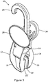
- Figure 5 is a perspective view of the clip 10 shown in figures 3 and 4 wherein the feature of the stop 40 on clip half 14 is more clearly visible.
- the stop 40 abuts a point 41 on the other clip half 12 by virtue of the force exerted by the biasing component. This ensures that the gripping surfaces 22, 24 are not urged toward one another by a biasing force.
- the pushable surface 30 has been urged towards the area for information 28 so that the gripping surfaces 22, 24 have been moved away from one another about pivot point 16.
- An item can be placed between the gripping surfaces 22, 24 and the force being applied to the pushable surface 30 and/or the area for information 28 can be released.
- the biasing force returns the clip to its closed position as shown in figure 3 and the item is gripped.
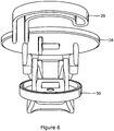
- Figure 6 shows an end on view of the clip according to the embodiments shown in figure 1 or 3 .
- the clip halves 12, 14 are biased by an anti-twist spring 34 to maintain the clip in the closed configuration shown in figures 1 , 3 and 4 .
- a force In order to move the clip from the position shown in figures 1 , 3 and 4 to that shown in figures 2 and 5 , a force must be applied to the pushable surface 30 and/or information area 28 which is greater than the force exerted by the spring 34.
- Figure 7 is a close up of the pushable surface 30 to which pressure can be applied to pivot the clip halves about pivot point 16.
- ridges 36 can also be provided.
- the pushable surface 30 defines a kimble hole 38 through which a fixing means can be passed.
- the fixing means is also attachable to the item to be retained by the clip 10 thereby ensuring the item to be retained is connected to the clip by an additional means.
- Figure 8 shows one of the clip halves 14.
- the clip half 14 has lugs 42 which are tapered so that when this clip half is pressed against the complementary clip half shown in figure 9 the lugs progressively deform the lug retainers 44 until the lug enters the recess defined by the lug retainer 44.
- the lug retainer 44 is a closed loop.
- the lugs 42 and lug retainers 44 effect a pivotal connection of the two clip halves, and therefore the clip 10, at pivot point 16.
- a biasing means 34 is inserted between the two clip halves 12, 14 before they are pressed together to form the clip 10.
- the present invention overcomes the problems of the prior art by providing an alternative means of manufacturing and assembling a clip and an improved clip.
Landscapes
- Engineering & Computer Science (AREA)
- General Engineering & Computer Science (AREA)
- Mechanical Engineering (AREA)
- Textile Engineering (AREA)
- Clamps And Clips (AREA)
- Sheet Holders (AREA)
Description
- The present invention relates to a clip and a method of manufacturing a clip. The clip can be suited to a number of applications.
- The term clip used herein is to be understood as encompassing an object for holding an item in position. The item can include, but is not limited to, clothing, footwear, documents and household objects.
- Clips are well known in the prior art and exist in a number of embodiments such as hangers for garments, footwear, as clothes pegs or as clamps. There are a number of problems associated with known clips such as the methods of construction and assembly.
- The method of assembling a known clip is to slide a clip half having lugs into a recess between a lug retaining portion and a clip body of a complementary clip half. This compromises the strength of the moulding due to the force exerted on pushing the clip half with a lug into place. In order to overcome this problem the lug retaining portion has been made thick enough to withstand the force of the clip portion having lugs being pushed against it. However, this results in a lot of material being used which increases production costs.
- Some known clips have elastomeric pads on the gripping portion to reduce damage to the item they are retaining. This is particularly the case when the item to be retained is heavy and a strong gripping force is required. These clips suffer with the problem of the pads becoming stuck together when not in use. This may be as a result of the pads becoming warm during transport or storage but also because a spring is used to urge the pads together. In order to overcome this problem it has been known to place a thin, plastic strip between the pads. However, this is a time consuming step as the strip needs to be inserted before shipping or storage and then removed before use. It is also wasteful of materials. A solution to this problem is to have at least one protrusion on the gripping surface to hold apart the gripping surfaces. However, these protrusions can mark and/or damage the item they are retaining which is undesirable.
-
- The present invention is set out in the appended claims. Any embodiments, aspects or examples of the present description/disclosure that do not fall within the scope of said claims are provided for illustrative purposes only and do not form part of the present invention.
- The present invention, in at least some of its embodiments, seeks to solve some of the problems mentioned above.
- In an embodiment the invention relates to a clip comprising: a pair of opposed gripping portions each having a gripping surface, each gripping portion being located on a clip half, wherein one clip half further includes a stop spaced apart from the gripping portion which is engageable with a point spaced apart from the gripping portion on the other clip half.
- The terms half and halves used herein are intended to mean two parts which form a clip and is not intended to mean that they are equal in size or are mirror images. In an embodiment, the clip halves are biased by a biasing means to urge the stop against a point on the other clip half so as to prevent the gripping surfaces from being urged together by a force exerted by the biasing means. The stop is engageable with the point on the other clip half by virtue of simply abutting the point or the clip half having an indentation for receiving the stop.
- The provision of a stop prevents the gripping surfaces from being urged together as the stop on one clip half and the point on the other clip half are urged together instead. This prevents, or lessens, the chance of the gripping surfaces becoming stuck together by virtue of the force exerted by the biasing means. The stop can be dimensioned so that it allows at least a part of the opposing gripping surfaces to touch each other. Alternatively, the stop can be dimensioned to ensure that the opposing gripping surfaces do not touch each other. The dimension of the stop depends upon the desired use of the clip and the item to be retained. For example, the inventors have found it is desirable to have the gripping surfaces to be held apart by a small distance when the item to be retained is a pair of boots, for example. Alternatively, if the item to be retained is thin then it will be favourable for the gripping portions to be touching in a non-use configuration so that the thin item is retained and the stop will be of a smaller dimension than the stop on a clip used to retain a large item. If a large item is to be retained then a larger spacing apart of the gripping surfaces is acceptable so that the force exerted by the gripping surfaces does not cause damage to the item to be retained. This is achieved by having a stop of a larger dimension than a stop on a clip used to retain a thin item.
- The point may be any suitable feature for engaging with the stop, such as a surface, a raised feature or a receptacle.
- In an embodiment, the two clip halves are biased by a biasing means in the form of a spring. In a further embodiment, the spring is an anti-twist spring which ensures the gripping force exerted by the gripping portions on the item to be retained is distributed evenly.
- In an embodiment, the clip halves are in pivotal connection with each other. A pivoting force may be applied to at least one of the halves so that at least one of the halves pivots thereby moving the gripping portions away from each other so that an item to be retained can be placed between the gripping portions. The pivoting force applied needs to be greater than the force exerted by the biasing component. A user can grip both the clip halves and apply a force thereto causing at least one of the halves to pivot about the pivotal connection thereby distancing the gripping portions from one another so that an item to be retained can be placed between the gripping portions.
- In an embodiment, the pivotal connection can be effected by any suitable means. In an embodiment, one of the clip halves has at least one lug which is engageable with at least one lug retainer on the other clip half. In an embodiment, the lug retainer is a closed loop so an outer part of the lug retainer defines a recess into which the lug is engageable. The at least one lug engages with the at least one lug retainer and is maintained in place by an interference fit. In an embodiment, one clip half has two lugs and the other clip half has two lug retainers. In an embodiment, the lugs are tapered so that as the clip is assembled according to the method described below they progressively force the lug retainers apart to then allow the lugs to engage the lug retainers. Alternatively, a clip half may be formed with one lug and one lug retainer which are engageable with a complementary lug and lug retainer on the other clip half. The interference fit is strong enough to maintain the two clip halves in pivotal connection even without the biasing component being in place.
- In an embodiment at least one of the clip halves has a pushable surface on which a user can exert a force to cause at least one clip half to pivot about the pivotal connection. The pushable surface may be inclined with respect to the rest of the clip half to enable it to be pushed more easily by a user.
- In an embodiment the pushable surface defines a kimble hole through which a fastener is passed, the fastener is attachable to the item(s) to be retained by the clip. This attachment to the clip and the item(s) to be retained prevents the item becoming completely detached from the clip should the gripping force be removed for any reason. The fastener can be of any suitable material such as a plastic or metal tag.
- In an embodiment, the gripping surfaces may be formed of an elastomeric material. In another embodiment, the gripping surfaces are formed, at least in part, by thermoplastic elastomer (TPE). TPE is a tacky material and further assists in retaining the item between the gripping surfaces. Due to its tackiness, side to side movement of the item to be retained is limited. In another embodiment, the gripping surfaces are formed, at least in part, by acrylonitrile butadiene styrene (ABS). ABS is a flexible material and is stronger and lighter than TPE. In another embodiment, the gripping surfaces may be smooth or have teeth or serrations which may be opposed or staggered with respect to the teeth or serrations on the opposite clip half.
- In an embodiment, one of the clip halves has a suspension means connected thereto. The suspension means allows the clip to be suspended from a rack, or the like, thereby displaying the item retained by the clip.
- In another embodiment, one of the clip halves has a portion on which information can be displayed such as by a label affixed thereto. In an embodiment, this information portion is located near to the pivotal connection so it can also act as a pushable surface upon which a force can be applied. In an embodiment, the pushable surface on one clip half is opposing the information portion so that the pushable surface and label portions can be pushed towards each other so as to cause a pivoting motion to move the gripping portions away from each other when a force greater than that exerted by the biasing component is applied.
- In another embodiment the invention relates to a method of manufacturing a clip comprising the steps of forming two complementary clip halves wherein each clip half has a gripping portion having a gripping surface, one clip half has at least one lug retainer and the other clip half has at least one lug which is engageable with the at least one lug retainer on the complementary clip half, aligning the at least one lug with the at least one lug retainer, exerting a force on at least one of the clip halves so that the at least one lug causes the at least one lug retainer to deform in an outward direction, thereby allowing passage of the lug until it engages with the lug retainer.
- The clip formed by this method uses less material than known clips as the lug retainers are closed loop which defines a recess into which the lugs are retained. The lug retainers are robust enough to withstand the force required to connect the other clip half having lugs.
- In an embodiment, the method of manufacturing may be automated. The method can further comprise an additional step of inserting a biasing component between the two clip halves. In an embodiment the biasing component is a spring. In another embodiment, the biasing means is an anti-twist spring.
- The method of forming a clip half may include forming a first clip half having a stop which abuts a point on the second clip half when assembled. This stop is urged against the point on the second clip half by the biasing component.
- In an embodiment, one clip half is formed with two lugs and the complementary clip half is formed with two lug retainers. In a further embodiment, one clip half is formed with a lug and a lug retainer and the other clip half is formed with a complementary lug and lug retainer. In a further embodiment, the lugs are tapered to cause deformation of the lug retainer during assembly.
- The invention also relates to a method of attaching an item to a clip according to an embodiment described herein comprising the steps of: providing a clip according to an embodiment of the invention; exerting a pivoting force on at least one of the clip halves to overcome the force exerted by the biasing component; positioning the gripping portions either side of an item or items to be retained by the clip; and releasing the pivoting force thereby allowing the gripping surfaces to contact the item to be retained. The clip may be configured to be any size which is suitable for the intended purpose. For example, the clip can be the size of a clothes peg for retaining clothes or a large clamp for gripping larger objects. The clip can be manufactured from any suitable material. In an embodiment, the clip is manufactured from plastic, preferably recycled plastic, and the spring is made of metal.
- Whilst the invention has been described above, it extends to any inventive combination as set out above or in the following description, drawings or claims.
- Embodiments of clips in accordance with at least one embodiment will be described, by way of example only, with reference to the accompanying drawings in which:
- Figure 1
- shows an assembled clip made according to the method disclosed herein.
- Figure 2
- shows the clip of
figure 1 in an opened configuration. - Figure 3
- shows a clip according to another embodiment of the invention.
- Figure 4
- is a side on view of the clip of
figure 3 . - Figure 5
- is a perspective view of the clip shown in
figures 3 and4 . - Figure 6
- shows an end on view of the clip shown in
figure 1 or3 . - Figure 7
- is a close up of the pushable surface on a clip according to one embodiment.
- Figure 8
- is a front view of a clip half according to an embodiment of the invention.
- Figure 9
- is a front view of a clip half which is complementary to the clip half of
figure 8 . -
Figure 1 shows aclip 10 in a closed, non-use configuration which has been manufactured according to a method of manufacture described herein. Theclip 10 includes twoclip halves pivot point 16. The two clip halves havegripping portions surface figure 1 , the gripping surfaces are teeth. The two halves are biased to ensure the gripping surfaces are close, or even touching each other, in a non-use position, as is shown in this figure. This embodiment shows a clip for footwear which also includes a suspension means 26 and anarea 28 upon which information can be displayed. -
Figure 2 shows the clip offigure 1 in an opened configuration. At least one of the clip halves 12, 14 has been pivoted aboutpivot point 16 in order to move thegripping surfaces pushable surface 30, theinformation area 28 or both of these. An item to be displayed, such as a pair of boots, can be placed between thegripping surfaces teeth 32. The pressure is released from the pushable surface and/orinformation area 28 and the clip returns to its closed configuration, as shown infigure 1 by virtue of a biasing component, not shown, which allows the clip to grip the item to be displayed. -
Figure 3 shows aclip 10 according to an embodiment of the invention which has many features in common with the clip shown infigure 1 . The clip is operated in the same way as that shown infigure 1 and2 and can be manufactured by the method described herein. It is also suited to displaying footwear. In this embodiment, the grippingsurfaces -
Figure 4 is a side on view of theclip 10 offigure 3 . It can be seen that the grippingsurfaces stop 40, which is located onclip half 14 and spaced apart from the grippingsurface 24, which abuts theother clip half 12 at apoint 41 spaced apart from the grippingsurface 22. Thestop 40 is urged towards the other clip half by a biasing component, which is not shown. As the biasing component exerts a force on thestop 40 and abutting portion of the other clip half, there is little or no force exerted on thegripping surfaces gripping surfaces stop 40/point 41 mechanism fails to hold thegripping surfaces -
Figure 5 is a perspective view of theclip 10 shown infigures 3 and4 wherein the feature of thestop 40 onclip half 14 is more clearly visible. Thestop 40 abuts apoint 41 on theother clip half 12 by virtue of the force exerted by the biasing component. This ensures that the grippingsurfaces pushable surface 30 has been urged towards the area forinformation 28 so that the grippingsurfaces pivot point 16. An item can be placed between thegripping surfaces pushable surface 30 and/or the area forinformation 28 can be released. The biasing force returns the clip to its closed position as shown infigure 3 and the item is gripped. -
Figure 6 shows an end on view of the clip according to the embodiments shown infigure 1 or3 . The clip halves 12, 14 are biased by an anti-twist spring 34 to maintain the clip in the closed configuration shown infigures 1 ,3 and4 . In order to move the clip from the position shown infigures 1 ,3 and4 to that shown infigures 2 and5 , a force must be applied to thepushable surface 30 and/orinformation area 28 which is greater than the force exerted by the spring 34. -
Figure 7 is a close up of thepushable surface 30 to which pressure can be applied to pivot the clip halves aboutpivot point 16. To ensure a good grip on the pushable surface is achieved,ridges 36 can also be provided. Thepushable surface 30 defines akimble hole 38 through which a fixing means can be passed. The fixing means is also attachable to the item to be retained by theclip 10 thereby ensuring the item to be retained is connected to the clip by an additional means. -
Figure 8 shows one of the clip halves 14. Theclip half 14 haslugs 42 which are tapered so that when this clip half is pressed against the complementary clip half shown infigure 9 the lugs progressively deform thelug retainers 44 until the lug enters the recess defined by thelug retainer 44. Thelug retainer 44 is a closed loop. Thelugs 42 and lugretainers 44 effect a pivotal connection of the two clip halves, and therefore theclip 10, atpivot point 16. In an embodiment, a biasing means 34 is inserted between the twoclip halves clip 10. - The present invention overcomes the problems of the prior art by providing an alternative means of manufacturing and assembling a clip and an improved clip.
Claims (15)
- A clip (10) comprising:a pair of opposed gripping portions (18, 20) each having a gripping surface (22, 24), each gripping portion being located on a clip half (12, 14), wherein the clip halves (12, 14) are biased by a biasing component;
characterised in that
one clip half further includes a stop (40) spaced apart from the gripping portion which is engageable with a point (41) spaced apart from the gripping portion on the other clip half,wherein the clip halves (12, 14) are biased by the biasing component to urge the stop (40) against the point (41) on the other clip half so as to prevent the gripping surfaces (22, 24) from being urged together by the force exerted by the biasing component. - A clip (10) according to claim 1 wherein the biasing component is a spring (34).
- A clip according to claim 2 wherein the spring is an anti-twist spring.
- A clip (10) according to any of claims 1 to 3 wherein the clip halves (12, 14) are in pivotal connection with each other.
- A clip (10) according to claim 4 wherein the pivotal connection is effected by at least one lug (42) on one clip half being engageable with at least one lug retainer (44) on the other clip half.
- A clip (10) according to claim 5 wherein the at least one lug retainer (44) is a closed loop defining a recess into which the lug (42) is placed thereby providing a pivotal connection.
- A clip (10) according to any of claims 1 to 6 wherein the clip (10) further comprises a pushable surface (30).
- A clip (10) according to claim 7 wherein the pushable surface (30) further defines a kimble hole (38).
- A clip (10) according to any of claims 1 to 8 wherein the pushable surface opposes the portion to which information is attachable.
- A clip (10) according to any of claims 1 to 9 further comprising a suspension means (26).
- A clip (10) according to any of claims 1 to 10 further comprising a portion (2 8) to which information is attachable.
- A method of manufacturing a clip (10) comprising the steps of:forming complementary clip halves (12, 14) wherein each clip half (12, 14) has a gripping portion (18, 20) having a gripping surface (22, 24),wherein one of the clip halves has at least one lug retainer (44) and the other clip half has at least one lug (42) which is engageable with the lug retainer (44) on the other clip half; andwherein one of the clip halves includes a stop (40) spaced apart from the gripping portion which is engageable with a point (41) spaced apart from the gripping portion on the other clip half;aligning the at least one lug (42) with the at least one lug retainer (44), exerting a force on at least one of the clip halves (12, 14) so that the at least one lug (42) engages with the lug retainer (44); andinserting a biasing component between the two clip halves (12,14) to urge the stop (40) against the point (41) on the other clip half so as to prevent the gripping surfaces (22, 24) from being urged together by the force exerted by the biasing component.
- A method according to claim 12 wherein exerting a force on at least one of the clip halves (12, 14) causes the at least one lug (42) to deform the at least one lug retainer (44) in an outward direction, thereby allowing passage of the lug (42) until it engages with the lug retainer (44).
- A method according to claim 12 or 13 wherein one clip half is formed with two lugs (42) and the complementary clip half is formed with two lug retainers (44).
- A method of attaching an item to the clip (10) according to any of claims 1 to 11 comprising the steps of: providing a clip (10) according to an embodiment of the invention; exerting a pivoting force on at least one of the clip halves (12, 14) to overcome the force exerted by the biasing component; positioning the gripping portion (18, 20) either side of an item to be retained by the clip (10); and releasing the pivoting force.
Applications Claiming Priority (2)
| Application Number | Priority Date | Filing Date | Title |
|---|---|---|---|
| GBGB1415835.6A GB201415835D0 (en) | 2014-09-08 | 2014-09-08 | A Clip |
| PCT/GB2015/052593 WO2016038354A1 (en) | 2014-09-08 | 2015-09-08 | A clip |
Publications (2)
| Publication Number | Publication Date |
|---|---|
| EP3191718A1 EP3191718A1 (en) | 2017-07-19 |
| EP3191718B1 true EP3191718B1 (en) | 2019-07-10 |
Family
ID=51796342
Family Applications (1)
| Application Number | Title | Priority Date | Filing Date |
|---|---|---|---|
| EP15771228.2A Active EP3191718B1 (en) | 2014-09-08 | 2015-09-08 | A clip |
Country Status (5)
| Country | Link |
|---|---|
| US (1) | US10485366B2 (en) |
| EP (1) | EP3191718B1 (en) |
| DK (1) | DK3191718T3 (en) |
| GB (2) | GB201415835D0 (en) |
| WO (1) | WO2016038354A1 (en) |
Families Citing this family (7)
| Publication number | Priority date | Publication date | Assignee | Title |
|---|---|---|---|---|
| GB201415835D0 (en) | 2014-09-08 | 2014-10-22 | Phineas Products Ltd | A Clip |
| CN204445257U (en) * | 2015-01-12 | 2015-07-08 | 香港多耐福有限公司 | A webbing adjustment fixing hook |
| GB2537938B (en) * | 2015-05-01 | 2019-07-10 | Treemagineers Ltd | Throwing hook |
| USD895298S1 (en) * | 2019-02-19 | 2020-09-08 | Marguerite Marrelli | Towel clip with brush |
| USD902025S1 (en) * | 2019-04-07 | 2020-11-17 | Helen Of Troy Limited | Hook with clip |
| CA3170417A1 (en) * | 2020-03-13 | 2021-09-16 | Decolin Inc. | Shower curtain clips |
| GB202317493D0 (en) * | 2023-11-15 | 2023-12-27 | Phineas Group Uk Ltd | Hanger |
Family Cites Families (10)
| Publication number | Priority date | Publication date | Assignee | Title |
|---|---|---|---|---|
| US2950939A (en) * | 1960-08-30 | van volkenburgh | ||
| GB2167659A (en) | 1984-11-08 | 1986-06-04 | Polyoak Products | Hangers for clothing |
| US4807334A (en) * | 1988-04-28 | 1989-02-28 | Batts, Inc. | Article hanger clip |
| DE9210451U1 (en) * | 1992-06-09 | 1992-10-22 | Herbert Kannegiesser Gmbh + Co, 4973 Vlotho | Transport handle |
| JPH0824489A (en) * | 1994-07-14 | 1996-01-30 | Shoichi Suzuki | Grip |
| JP2001079294A (en) * | 1999-09-16 | 2001-03-27 | Sazanami Kk | Clothes pinch |
| DE20111315U1 (en) | 2000-10-06 | 2001-10-18 | Braitrim Deutschland GmbH, 32657 Lemgo | Holding clip for a hanger |
| GB0705791D0 (en) * | 2007-03-27 | 2007-05-02 | Phineas Products Ltd | Boot hanger |
| JP5995216B2 (en) * | 2012-08-23 | 2016-09-21 | 太文 長尾 | Pinching tool |
| GB201415835D0 (en) | 2014-09-08 | 2014-10-22 | Phineas Products Ltd | A Clip |
-
2014
- 2014-09-08 GB GBGB1415835.6A patent/GB201415835D0/en not_active Ceased
-
2015
- 2015-08-08 GB GB1703473.7A patent/GB2548017B/en active Active
- 2015-09-08 US US15/509,172 patent/US10485366B2/en active Active
- 2015-09-08 EP EP15771228.2A patent/EP3191718B1/en active Active
- 2015-09-08 DK DK15771228.2T patent/DK3191718T3/en active
- 2015-09-08 WO PCT/GB2015/052593 patent/WO2016038354A1/en not_active Ceased
Non-Patent Citations (1)
| Title |
|---|
| None * |
Also Published As
| Publication number | Publication date |
|---|---|
| DK3191718T3 (en) | 2019-10-21 |
| EP3191718A1 (en) | 2017-07-19 |
| GB201703473D0 (en) | 2017-04-19 |
| US10485366B2 (en) | 2019-11-26 |
| GB201415835D0 (en) | 2014-10-22 |
| US20170265665A1 (en) | 2017-09-21 |
| GB2548017B (en) | 2020-07-08 |
| WO2016038354A1 (en) | 2016-03-17 |
| GB2548017A (en) | 2017-09-06 |
Similar Documents
| Publication | Publication Date | Title |
|---|---|---|
| US10485366B2 (en) | Clip | |
| US5640742A (en) | Spring badge clip | |
| US5452500A (en) | One piece spring clip | |
| CN107533816B (en) | Device for supporting electronic labels | |
| AU635426B2 (en) | Improved clip for garment hanger | |
| US9909341B2 (en) | Removable attachment device for attaching to longer linear or filiform objects | |
| US20100000257A1 (en) | Purse hanger | |
| GB2327975A (en) | Holding device | |
| US20070228088A1 (en) | Pinch clip garment hanger with modular friction pads | |
| KR102161327B1 (en) | Fastening method and apparatus | |
| US20160353845A1 (en) | Fastening tool | |
| JP5511111B1 (en) | Pinch tool | |
| US20070012832A1 (en) | Secure peg hook | |
| US20130292533A1 (en) | Object holder | |
| US20240328060A1 (en) | Clothes hanger clips | |
| US20090001108A1 (en) | Releasably lockable pinch grip hanger | |
| US10221518B2 (en) | Skirt clip | |
| US6508388B1 (en) | Hanger | |
| EP3704999B1 (en) | Clothes hanger | |
| US20170065015A1 (en) | Apparatus for applying studs | |
| GB2631941A (en) | A garment hanger | |
| CN103104578B (en) | Clamper | |
| JP6751971B2 (en) | clip | |
| EP3181016B1 (en) | Method for forming a reusable hanging device | |
| KR20140040785A (en) | Clamp |
Legal Events
| Date | Code | Title | Description |
|---|---|---|---|
| STAA | Information on the status of an ep patent application or granted ep patent |
Free format text: STATUS: THE INTERNATIONAL PUBLICATION HAS BEEN MADE |
|
| PUAI | Public reference made under article 153(3) epc to a published international application that has entered the european phase |
Free format text: ORIGINAL CODE: 0009012 |
|
| STAA | Information on the status of an ep patent application or granted ep patent |
Free format text: STATUS: REQUEST FOR EXAMINATION WAS MADE |
|
| 17P | Request for examination filed |
Effective date: 20170303 |
|
| AK | Designated contracting states |
Kind code of ref document: A1 Designated state(s): AL AT BE BG CH CY CZ DE DK EE ES FI FR GB GR HR HU IE IS IT LI LT LU LV MC MK MT NL NO PL PT RO RS SE SI SK SM TR |
|
| AX | Request for extension of the european patent |
Extension state: BA ME |
|
| DAV | Request for validation of the european patent (deleted) | ||
| DAX | Request for extension of the european patent (deleted) | ||
| STAA | Information on the status of an ep patent application or granted ep patent |
Free format text: STATUS: EXAMINATION IS IN PROGRESS |
|
| 17Q | First examination report despatched |
Effective date: 20180622 |
|
| GRAP | Despatch of communication of intention to grant a patent |
Free format text: ORIGINAL CODE: EPIDOSNIGR1 |
|
| STAA | Information on the status of an ep patent application or granted ep patent |
Free format text: STATUS: GRANT OF PATENT IS INTENDED |
|
| INTG | Intention to grant announced |
Effective date: 20190128 |
|
| GRAS | Grant fee paid |
Free format text: ORIGINAL CODE: EPIDOSNIGR3 |
|
| GRAA | (expected) grant |
Free format text: ORIGINAL CODE: 0009210 |
|
| STAA | Information on the status of an ep patent application or granted ep patent |
Free format text: STATUS: THE PATENT HAS BEEN GRANTED |
|
| AK | Designated contracting states |
Kind code of ref document: B1 Designated state(s): AL AT BE BG CH CY CZ DE DK EE ES FI FR GB GR HR HU IE IS IT LI LT LU LV MC MK MT NL NO PL PT RO RS SE SI SK SM TR |
|
| REG | Reference to a national code |
Ref country code: GB Ref legal event code: FG4D |
|
| REG | Reference to a national code |
Ref country code: CH Ref legal event code: EP Ref country code: AT Ref legal event code: REF Ref document number: 1153866 Country of ref document: AT Kind code of ref document: T Effective date: 20190715 |
|
| REG | Reference to a national code |
Ref country code: DE Ref legal event code: R096 Ref document number: 602015033568 Country of ref document: DE |
|
| REG | Reference to a national code |
Ref country code: IE Ref legal event code: FG4D |
|
| REG | Reference to a national code |
Ref country code: DK Ref legal event code: T3 Effective date: 20191015 |
|
| REG | Reference to a national code |
Ref country code: NL Ref legal event code: MP Effective date: 20190710 |
|
| REG | Reference to a national code |
Ref country code: LT Ref legal event code: MG4D |
|
| REG | Reference to a national code |
Ref country code: AT Ref legal event code: MK05 Ref document number: 1153866 Country of ref document: AT Kind code of ref document: T Effective date: 20190710 |
|
| PG25 | Lapsed in a contracting state [announced via postgrant information from national office to epo] |
Ref country code: FI Free format text: LAPSE BECAUSE OF FAILURE TO SUBMIT A TRANSLATION OF THE DESCRIPTION OR TO PAY THE FEE WITHIN THE PRESCRIBED TIME-LIMIT Effective date: 20190710 Ref country code: LT Free format text: LAPSE BECAUSE OF FAILURE TO SUBMIT A TRANSLATION OF THE DESCRIPTION OR TO PAY THE FEE WITHIN THE PRESCRIBED TIME-LIMIT Effective date: 20190710 Ref country code: BG Free format text: LAPSE BECAUSE OF FAILURE TO SUBMIT A TRANSLATION OF THE DESCRIPTION OR TO PAY THE FEE WITHIN THE PRESCRIBED TIME-LIMIT Effective date: 20191010 Ref country code: NL Free format text: LAPSE BECAUSE OF FAILURE TO SUBMIT A TRANSLATION OF THE DESCRIPTION OR TO PAY THE FEE WITHIN THE PRESCRIBED TIME-LIMIT Effective date: 20190710 Ref country code: PT Free format text: LAPSE BECAUSE OF FAILURE TO SUBMIT A TRANSLATION OF THE DESCRIPTION OR TO PAY THE FEE WITHIN THE PRESCRIBED TIME-LIMIT Effective date: 20191111 Ref country code: NO Free format text: LAPSE BECAUSE OF FAILURE TO SUBMIT A TRANSLATION OF THE DESCRIPTION OR TO PAY THE FEE WITHIN THE PRESCRIBED TIME-LIMIT Effective date: 20191010 Ref country code: AT Free format text: LAPSE BECAUSE OF FAILURE TO SUBMIT A TRANSLATION OF THE DESCRIPTION OR TO PAY THE FEE WITHIN THE PRESCRIBED TIME-LIMIT Effective date: 20190710 Ref country code: HR Free format text: LAPSE BECAUSE OF FAILURE TO SUBMIT A TRANSLATION OF THE DESCRIPTION OR TO PAY THE FEE WITHIN THE PRESCRIBED TIME-LIMIT Effective date: 20190710 Ref country code: SE Free format text: LAPSE BECAUSE OF FAILURE TO SUBMIT A TRANSLATION OF THE DESCRIPTION OR TO PAY THE FEE WITHIN THE PRESCRIBED TIME-LIMIT Effective date: 20190710 |
|
| PG25 | Lapsed in a contracting state [announced via postgrant information from national office to epo] |
Ref country code: IS Free format text: LAPSE BECAUSE OF FAILURE TO SUBMIT A TRANSLATION OF THE DESCRIPTION OR TO PAY THE FEE WITHIN THE PRESCRIBED TIME-LIMIT Effective date: 20191110 Ref country code: RS Free format text: LAPSE BECAUSE OF FAILURE TO SUBMIT A TRANSLATION OF THE DESCRIPTION OR TO PAY THE FEE WITHIN THE PRESCRIBED TIME-LIMIT Effective date: 20190710 Ref country code: AL Free format text: LAPSE BECAUSE OF FAILURE TO SUBMIT A TRANSLATION OF THE DESCRIPTION OR TO PAY THE FEE WITHIN THE PRESCRIBED TIME-LIMIT Effective date: 20190710 Ref country code: GR Free format text: LAPSE BECAUSE OF FAILURE TO SUBMIT A TRANSLATION OF THE DESCRIPTION OR TO PAY THE FEE WITHIN THE PRESCRIBED TIME-LIMIT Effective date: 20191011 Ref country code: ES Free format text: LAPSE BECAUSE OF FAILURE TO SUBMIT A TRANSLATION OF THE DESCRIPTION OR TO PAY THE FEE WITHIN THE PRESCRIBED TIME-LIMIT Effective date: 20190710 Ref country code: LV Free format text: LAPSE BECAUSE OF FAILURE TO SUBMIT A TRANSLATION OF THE DESCRIPTION OR TO PAY THE FEE WITHIN THE PRESCRIBED TIME-LIMIT Effective date: 20190710 |
|
| PG25 | Lapsed in a contracting state [announced via postgrant information from national office to epo] |
Ref country code: TR Free format text: LAPSE BECAUSE OF FAILURE TO SUBMIT A TRANSLATION OF THE DESCRIPTION OR TO PAY THE FEE WITHIN THE PRESCRIBED TIME-LIMIT Effective date: 20190710 |
|
| PG25 | Lapsed in a contracting state [announced via postgrant information from national office to epo] |
Ref country code: EE Free format text: LAPSE BECAUSE OF FAILURE TO SUBMIT A TRANSLATION OF THE DESCRIPTION OR TO PAY THE FEE WITHIN THE PRESCRIBED TIME-LIMIT Effective date: 20190710 Ref country code: PL Free format text: LAPSE BECAUSE OF FAILURE TO SUBMIT A TRANSLATION OF THE DESCRIPTION OR TO PAY THE FEE WITHIN THE PRESCRIBED TIME-LIMIT Effective date: 20190710 Ref country code: IT Free format text: LAPSE BECAUSE OF FAILURE TO SUBMIT A TRANSLATION OF THE DESCRIPTION OR TO PAY THE FEE WITHIN THE PRESCRIBED TIME-LIMIT Effective date: 20190710 Ref country code: RO Free format text: LAPSE BECAUSE OF FAILURE TO SUBMIT A TRANSLATION OF THE DESCRIPTION OR TO PAY THE FEE WITHIN THE PRESCRIBED TIME-LIMIT Effective date: 20190710 |
|
| PG25 | Lapsed in a contracting state [announced via postgrant information from national office to epo] |
Ref country code: SK Free format text: LAPSE BECAUSE OF FAILURE TO SUBMIT A TRANSLATION OF THE DESCRIPTION OR TO PAY THE FEE WITHIN THE PRESCRIBED TIME-LIMIT Effective date: 20190710 Ref country code: MC Free format text: LAPSE BECAUSE OF FAILURE TO SUBMIT A TRANSLATION OF THE DESCRIPTION OR TO PAY THE FEE WITHIN THE PRESCRIBED TIME-LIMIT Effective date: 20190710 Ref country code: IS Free format text: LAPSE BECAUSE OF FAILURE TO SUBMIT A TRANSLATION OF THE DESCRIPTION OR TO PAY THE FEE WITHIN THE PRESCRIBED TIME-LIMIT Effective date: 20200224 Ref country code: CZ Free format text: LAPSE BECAUSE OF FAILURE TO SUBMIT A TRANSLATION OF THE DESCRIPTION OR TO PAY THE FEE WITHIN THE PRESCRIBED TIME-LIMIT Effective date: 20190710 Ref country code: SM Free format text: LAPSE BECAUSE OF FAILURE TO SUBMIT A TRANSLATION OF THE DESCRIPTION OR TO PAY THE FEE WITHIN THE PRESCRIBED TIME-LIMIT Effective date: 20190710 |
|
| REG | Reference to a national code |
Ref country code: CH Ref legal event code: PL |
|
| REG | Reference to a national code |
Ref country code: DE Ref legal event code: R097 Ref document number: 602015033568 Country of ref document: DE |
|
| PLBE | No opposition filed within time limit |
Free format text: ORIGINAL CODE: 0009261 |
|
| STAA | Information on the status of an ep patent application or granted ep patent |
Free format text: STATUS: NO OPPOSITION FILED WITHIN TIME LIMIT |
|
| PG2D | Information on lapse in contracting state deleted |
Ref country code: IS |
|
| PG25 | Lapsed in a contracting state [announced via postgrant information from national office to epo] |
Ref country code: LU Free format text: LAPSE BECAUSE OF NON-PAYMENT OF DUE FEES Effective date: 20190908 Ref country code: LI Free format text: LAPSE BECAUSE OF NON-PAYMENT OF DUE FEES Effective date: 20190930 Ref country code: CH Free format text: LAPSE BECAUSE OF NON-PAYMENT OF DUE FEES Effective date: 20190930 |
|
| REG | Reference to a national code |
Ref country code: BE Ref legal event code: MM Effective date: 20190930 |
|
| 26N | No opposition filed |
Effective date: 20200603 |
|
| PG25 | Lapsed in a contracting state [announced via postgrant information from national office to epo] |
Ref country code: SI Free format text: LAPSE BECAUSE OF FAILURE TO SUBMIT A TRANSLATION OF THE DESCRIPTION OR TO PAY THE FEE WITHIN THE PRESCRIBED TIME-LIMIT Effective date: 20190710 Ref country code: BE Free format text: LAPSE BECAUSE OF NON-PAYMENT OF DUE FEES Effective date: 20190930 |
|
| REG | Reference to a national code |
Ref country code: DE Ref legal event code: R082 Ref document number: 602015033568 Country of ref document: DE Representative=s name: HL KEMPNER PATENTANWAELTE, SOLICITORS (ENGLAND, DE Ref country code: DE Ref legal event code: R082 Ref document number: 602015033568 Country of ref document: DE Representative=s name: HL KEMPNER PATENTANWALT, RECHTSANWALT, SOLICIT, DE Ref country code: DE Ref legal event code: R082 Ref document number: 602015033568 Country of ref document: DE Representative=s name: HL KEMPNER PARTG MBB, DE |
|
| PG25 | Lapsed in a contracting state [announced via postgrant information from national office to epo] |
Ref country code: CY Free format text: LAPSE BECAUSE OF FAILURE TO SUBMIT A TRANSLATION OF THE DESCRIPTION OR TO PAY THE FEE WITHIN THE PRESCRIBED TIME-LIMIT Effective date: 20190710 |
|
| PG25 | Lapsed in a contracting state [announced via postgrant information from national office to epo] |
Ref country code: MT Free format text: LAPSE BECAUSE OF FAILURE TO SUBMIT A TRANSLATION OF THE DESCRIPTION OR TO PAY THE FEE WITHIN THE PRESCRIBED TIME-LIMIT Effective date: 20190710 Ref country code: HU Free format text: LAPSE BECAUSE OF FAILURE TO SUBMIT A TRANSLATION OF THE DESCRIPTION OR TO PAY THE FEE WITHIN THE PRESCRIBED TIME-LIMIT; INVALID AB INITIO Effective date: 20150908 |
|
| PG25 | Lapsed in a contracting state [announced via postgrant information from national office to epo] |
Ref country code: MK Free format text: LAPSE BECAUSE OF FAILURE TO SUBMIT A TRANSLATION OF THE DESCRIPTION OR TO PAY THE FEE WITHIN THE PRESCRIBED TIME-LIMIT Effective date: 20190710 |
|
| PGFP | Annual fee paid to national office [announced via postgrant information from national office to epo] |
Ref country code: DE Payment date: 20241010 Year of fee payment: 10 |
|
| PGFP | Annual fee paid to national office [announced via postgrant information from national office to epo] |
Ref country code: DK Payment date: 20241016 Year of fee payment: 10 |
|
| PGFP | Annual fee paid to national office [announced via postgrant information from national office to epo] |
Ref country code: FR Payment date: 20241010 Year of fee payment: 10 |
|
| PGFP | Annual fee paid to national office [announced via postgrant information from national office to epo] |
Ref country code: IE Payment date: 20241029 Year of fee payment: 10 |
|
| PGFP | Annual fee paid to national office [announced via postgrant information from national office to epo] |
Ref country code: GB Payment date: 20250929 Year of fee payment: 11 |
|
| REG | Reference to a national code |
Ref country code: DK Ref legal event code: EBP Effective date: 20250930 |