EP3190722A1 - Dispersion detection method and device in optical transmission network, and storage medium - Google Patents
Dispersion detection method and device in optical transmission network, and storage medium Download PDFInfo
- Publication number
- EP3190722A1 EP3190722A1 EP15836728.4A EP15836728A EP3190722A1 EP 3190722 A1 EP3190722 A1 EP 3190722A1 EP 15836728 A EP15836728 A EP 15836728A EP 3190722 A1 EP3190722 A1 EP 3190722A1
- Authority
- EP
- European Patent Office
- Prior art keywords
- data
- value
- frequency
- polarization states
- domain
- Prior art date
- Legal status (The legal status is an assumption and is not a legal conclusion. Google has not performed a legal analysis and makes no representation as to the accuracy of the status listed.)
- Granted
Links
Images


Classifications
-
- H—ELECTRICITY
- H04—ELECTRIC COMMUNICATION TECHNIQUE
- H04B—TRANSMISSION
- H04B10/00—Transmission systems employing electromagnetic waves other than radio-waves, e.g. infrared, visible or ultraviolet light, or employing corpuscular radiation, e.g. quantum communication
- H04B10/60—Receivers
- H04B10/61—Coherent receivers
- H04B10/616—Details of the electronic signal processing in coherent optical receivers
- H04B10/6161—Compensation of chromatic dispersion
-
- H—ELECTRICITY
- H04—ELECTRIC COMMUNICATION TECHNIQUE
- H04B—TRANSMISSION
- H04B10/00—Transmission systems employing electromagnetic waves other than radio-waves, e.g. infrared, visible or ultraviolet light, or employing corpuscular radiation, e.g. quantum communication
- H04B10/07—Arrangements for monitoring or testing transmission systems; Arrangements for fault measurement of transmission systems
- H04B10/075—Arrangements for monitoring or testing transmission systems; Arrangements for fault measurement of transmission systems using an in-service signal
- H04B10/079—Arrangements for monitoring or testing transmission systems; Arrangements for fault measurement of transmission systems using an in-service signal using measurements of the data signal
- H04B10/0795—Performance monitoring; Measurement of transmission parameters
- H04B10/07951—Monitoring or measuring chromatic dispersion or PMD
-
- H—ELECTRICITY
- H04—ELECTRIC COMMUNICATION TECHNIQUE
- H04B—TRANSMISSION
- H04B10/00—Transmission systems employing electromagnetic waves other than radio-waves, e.g. infrared, visible or ultraviolet light, or employing corpuscular radiation, e.g. quantum communication
- H04B10/50—Transmitters
- H04B10/58—Compensation for non-linear transmitter output
-
- H—ELECTRICITY
- H04—ELECTRIC COMMUNICATION TECHNIQUE
- H04B—TRANSMISSION
- H04B10/00—Transmission systems employing electromagnetic waves other than radio-waves, e.g. infrared, visible or ultraviolet light, or employing corpuscular radiation, e.g. quantum communication
- H04B10/60—Receivers
- H04B10/61—Coherent receivers
- H04B10/616—Details of the electronic signal processing in coherent optical receivers
- H04B10/6162—Compensation of polarization related effects, e.g., PMD, PDL
-
- H—ELECTRICITY
- H04—ELECTRIC COMMUNICATION TECHNIQUE
- H04B—TRANSMISSION
- H04B10/00—Transmission systems employing electromagnetic waves other than radio-waves, e.g. infrared, visible or ultraviolet light, or employing corpuscular radiation, e.g. quantum communication
- H04B10/25—Arrangements specific to fibre transmission
- H04B10/2507—Arrangements specific to fibre transmission for the reduction or elimination of distortion or dispersion
- H04B10/2513—Arrangements specific to fibre transmission for the reduction or elimination of distortion or dispersion due to chromatic dispersion
- H04B10/25133—Arrangements specific to fibre transmission for the reduction or elimination of distortion or dispersion due to chromatic dispersion including a lumped electrical or optical dispersion compensator
Definitions
- the disclosure relates to an optical communication technology, and more particularly to a Chromatic Dispersion (CD) detection method and device for an optical transmission network and a storage medium.
- CD Chromatic Dispersion
- CD generated an optical signal in a transmission process becomes increasingly serious, and the CD may cause distortion of the transmitted signal, thereby resulting in a transmission error.
- it is necessary to compensate for the CD it is necessary to compensate for the CD, and the key for CD compensation is to accurately estimate a CD value.
- embodiments of the disclosure are desired to provide a CD detection method and device for an optical transmission network and a storage medium.
- the embodiments of the disclosure further provide a CD detection device for an optical transmission network comprising: a data conversion module, a data extraction module, a linear combination operation module, an argument acquisition module and a CD estimation module, the data conversion module is configured to convert data of two polarization states orthogonal to each other from time-domain data to frequency-domain data; the data extraction module is configured to perform extraction on the frequency-domain data, and send the extracted frequency-domain data to the linear combination operation module; the linear combination operation module is configured to perform a linear combination operation on the extracted frequency-domain data, and send a result of the linear combination operation to the argument acquisition module; the argument acquisition module is configured to obtain an argument of a CD value of the data of the two polarization states according to the result of the linear combination operation, and send the argument of the CD value to the CD estimation module; and the CD estimation module is configured to estimate the CD value according to the argument of the CD value of the data of the two polarization states.
- the embodiments of the disclosure further provide a computer storage medium in which a computer program is stored for execution of the above CD detection method for the optical transmission network.
- the embodiments of the disclosure provide the CD detection method and device for the optical transmission network and the storage medium, data of two polarization states orthogonal to each other is converted from time-domain data to frequency-domain data, extraction is performed on the frequency-domain data and a linear combination operation is performed on the frequency-domain data, an argument of a CD value of the data of the two polarization states is obtained according to a result of the linear combination operation, and the CD value is estimated according to the argument of the CD value of the data of the two polarization states; as such, an electric domain estimation may be performed on CD of the optical transmission network to implement CD detection for the optical transmission network.
- data of two polarization states orthogonal to each other is converted from time-domain data to frequency-domain data, extraction is performed on the frequency-domain data and a linear combination operation is performed on the extracted frequency-domain data, an argument of a CD value of the data of the two polarization states is obtained according to a result of the linear combination operation, and the CD value is estimated according to the argument of the CD value of the data of the two polarization states.
- the embodiments of the disclosure implement a CD detection method for an optical transmission network. As shown in Fig. 1 , the method includes the following steps.
- Step 101 data of two polarization states orthogonal to each other is converted from time-domain data to frequency-domain data.
- a special algorithm of discrete Fourier transform i.e. Fast Fourier Transform (FFT)
- N 2 t and t being a natural number
- Z k X + i k ⁇ Y k
- W N e ⁇ j 2 ⁇ N
- z(n) represents a sampled time-domain signal sequence
- z(n) x(n)+i ⁇ y(n)
- Z(k) is a frequency-domain signal corresponding to the sequence
- Step 102 extraction is performed on the frequency-domain data.
- Step 103 a linear combination operation is performed on the extracted frequency-domain data.
- Step 103d low-pass filtering is performed on a number T of accumulated values F 1 and a number M of accumulated values F 2 thus obtained to get F 1 and F 2 :
- the disclosure further provides a CD detection device for an optical transmission network.
- the device includes a data conversion module 21, a data extraction module 22, a linear combination operation module 23, an argument acquisition module 24 and a CD estimation module 25, in the device:
- the linear combination operation module 23 is specifically configured to:
- FIG. 3 A position of the CD detection device for the optical transmission network in the optical transmission network is shown in Fig. 3 .
- an optical signal passes through an Optical Fibre Amplifier (Erbium-doped Optical Fibre Amplifier, EDFA), a hybrid optical amplifier, a Balanced Photodiode Detector (BPD), an Analogue-to-Digital Converter (ADC), an In-phase/Quadrature (IQ) balance
- the data of the two polarization states orthogonal to each other is transmitted to the CD detection device (CD monitor) and CD compensation of the optical transmission network
- the CD monitor sends the estimated CD value to the CD compensation
- the CD compensation compensates for the CD value for other signal processing
- the optical signal is sent to a user-side interface after passing through a Forward Error Corrector (FEC) and a framer.
- FEC Forward Error Corrector
- the CD detection method for the optical transmission network may also be stored in a computer-readable storage medium.
- the technical solutions of the embodiments of the disclosure naturally or parts contributing to a conventional art may be embodied in form of a software product, and the computer software product is stored in a storage medium, including a plurality of instructions to enable a piece of computer equipment (which may be a personal computer, a server, network equipment or the like) to execute all or part of the method of each embodiment of the disclosure.
- the storage medium includes various media capable of storing program codes such as a U disk, a mobile hard disk, a Read-Only Memory (ROM), a magnetic disk or an optical disk. Therefore, the embodiments of the disclosure are not limited to any specific hardware and software combination.
- the embodiments of the disclosure further provide a computer storage medium in which a computer program is stored for execution of the CD detection method for the optical transmission network according to the embodiments of the disclosure.
- the data of the two polarization states orthogonal to each other is converted into the frequency-domain data and a linear combination operation is performed, the argument of the CD value of the data of the two polarization states are obtained, and the CD value is estimated according to the argument of the CD value. Therefore, electric domain estimation may be performed on CD of the optical transmission network to implement CD detection of the optical transmission network.
Landscapes
- Physics & Mathematics (AREA)
- Electromagnetism (AREA)
- Engineering & Computer Science (AREA)
- Computer Networks & Wireless Communication (AREA)
- Signal Processing (AREA)
- Nonlinear Science (AREA)
- Optical Communication System (AREA)
Abstract
Description
- The disclosure relates to an optical communication technology, and more particularly to a Chromatic Dispersion (CD) detection method and device for an optical transmission network and a storage medium.
- In an optical transmission network, with increase of a transmission length and a transmission baud rate, for example, in a 100Gbps ultralong-distance optical transmission network, CD generated an optical signal in a transmission process becomes increasingly serious, and the CD may cause distortion of the transmitted signal, thereby resulting in a transmission error. In order to eliminate influence of the CD, it is necessary to compensate for the CD, and the key for CD compensation is to accurately estimate a CD value.
- In order to solve the existing technical problem, embodiments of the disclosure are desired to provide a CD detection method and device for an optical transmission network and a storage medium.
- The technical solutions of the embodiments of the disclosure are implemented as follows.
- The embodiments of the disclosure provide a CD detection method for an optical transmission network comprising:
- converting data of two polarization states orthogonal to each other from time-domain data to frequency-domain data, performing extraction on the frequency-domain data and performing a linear combination operation on the extracted frequency-domain data, obtaining an argument of a CD value of the data of the two polarization states according to a result of the linear combination operation, and estimating the CD value according to the argument of the CD value of the data of the two polarization states.
- The embodiments of the disclosure further provide a CD detection device for an optical transmission network comprising: a data conversion module, a data extraction module, a linear combination operation module, an argument acquisition module and a CD estimation module,
the data conversion module is configured to convert data of two polarization states orthogonal to each other from time-domain data to frequency-domain data;
the data extraction module is configured to perform extraction on the frequency-domain data, and send the extracted frequency-domain data to the linear combination operation module;
the linear combination operation module is configured to perform a linear combination operation on the extracted frequency-domain data, and send a result of the linear combination operation to the argument acquisition module;
the argument acquisition module is configured to obtain an argument of a CD value of the data of the two polarization states according to the result of the linear combination operation, and send the argument of the CD value to the CD estimation module; and
the CD estimation module is configured to estimate the CD value according to the argument of the CD value of the data of the two polarization states. - The embodiments of the disclosure further provide a computer storage medium in which a computer program is stored for execution of the above CD detection method for the optical transmission network.
- The embodiments of the disclosure provide the CD detection method and device for the optical transmission network and the storage medium, data of two polarization states orthogonal to each other is converted from time-domain data to frequency-domain data, extraction is performed on the frequency-domain data and a linear combination operation is performed on the frequency-domain data, an argument of a CD value of the data of the two polarization states is obtained according to a result of the linear combination operation, and the CD value is estimated according to the argument of the CD value of the data of the two polarization states; as such, an electric domain estimation may be performed on CD of the optical transmission network to implement CD detection for the optical transmission network.
-
-
Fig. 1 is a schematic diagram of implementation of a flow of a CD detection method for an optical transmission network according to an embodiment of the disclosure; -
Fig. 2 is a schematic diagram of implementation of a structure of a CD detection device for an optical transmission network according to an embodiment of the disclosure; and -
Fig. 3 is a schematic diagram of a position of a CD detection device in an optical transmission network according to an embodiment of the disclosure. - In the embodiments of the disclosure, data of two polarization states orthogonal to each other is converted from time-domain data to frequency-domain data, extraction is performed on the frequency-domain data and a linear combination operation is performed on the extracted frequency-domain data, an argument of a CD value of the data of the two polarization states is obtained according to a result of the linear combination operation, and the CD value is estimated according to the argument of the CD value of the data of the two polarization states.
- The disclosure will be further described in detail below with reference to the drawings and specific embodiments.
- The embodiments of the disclosure implement a CD detection method for an optical transmission network. As shown in
Fig. 1 , the method includes the following steps. - In Step 101: data of two polarization states orthogonal to each other is converted from time-domain data to frequency-domain data.
- In the step, a special algorithm of discrete Fourier transform, i.e. Fast Fourier Transform (FFT), is adopted for implementation, with N = 2 t and t being a natural number, and the frequency-domain data converted from the data of the two polarization states being set as X(k) and Y(k), k=0, 1, ..., N-1, then


- In Step 102: extraction is performed on the frequency-domain data.
- In the step, the data is extracted from the frequency-domain data according to the following rules:


- In Step 103: a linear combination operation is performed on the extracted frequency-domain data.
- Here, the following steps are included.
- In Step 103a: two groups of sequences X 1 (U), X 2 (U) and X 3 (U) as well as X 1 (L), X 2 (L) and X 3 (L) in three different directions are obtained according to XU [k], XL [k], YU [k] and YL [k]:

- In Step 103b: conjugate multiplication is performed on the two groups of sequences X 1 (U), X 2 (U) and X 3 (U) as well as X 1 (L), X 2 (L) and X 3 (L) in the three different directions to obtain a CD sub-sequence R 1[k], R 2[k] and R 3[k] in the three different directions:

- In Step 103c: a first interval value is set as Δ1 = 2 and a second interval value is set as Δ2 = 32, and accumulated values F 1 and F 2 corresponding to these two interval values in different directions are calculated according to R 1[k], R 2[k] and R 3[k]:


- In Step 103d: low-pass filtering is performed on a number T of accumulated values F 1 and a number M of accumulated values F 2 thus obtained to get
F 1andF 2 :

- In Step 103e: two registers Buffer1 and Buffer2 with a length L are constructed, Buffer1 stores
F 1 calculated for recent L times, Buffer2 storesF 2 calculated for recent L times, initial values of Buffer1 and Buffer2 are both a number L of zeros, data in the Buffer1 is summed to obtain F 1_sum , and data in Buffer2 is summed to obtain F 2_sum :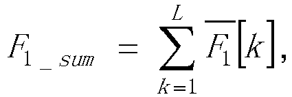

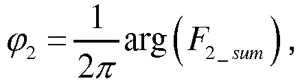
- In Step 104: the argument of the CD value of the data of the two polarization states is obtained according to the result of the linear combination operation;
particularly, the arguments ϕ 1 and ϕ 2 of the CD values of the data of the two polarization states are calculated respectively according to F 1_sum and F 2_sum :
- In Step 105: the CD value is estimated according to the argument of the CD value of the data of the two polarization states,
particularly, a CD estimation coefficient ϕ 1" is obtained according to the arguments ϕ 1 and ϕ 2 of the CD value of the data of the two polarization states, and a specific process is as follows:

- where floor(·) represents rounding down;

- when ϕ 2 u ≥ 0.5, u' = ϕ 2 - 1 ;
- when ϕ 2 u < -0.5, u' = ϕ 2 + 1; and
when - 0.5 ≤ ϕ 2 u < 0. 5, u' = ϕ 2;


- if ϕ 1" ≥ 0.25, a value obtained by ϕ 1"-0.5 is reassigned to ϕ 1"; and
- the CD value CD is estimated according to the CD estimation coefficient ϕ 1":

- In order to implement the abovementioned method, the disclosure further provides a CD detection device for an optical transmission network. As shown in
Fig. 2 , the device includes adata conversion module 21, adata extraction module 22, a linearcombination operation module 23, anargument acquisition module 24 and aCD estimation module 25, in the device: - the
data conversion module 21 is configured to convert data of two polarization states orthogonal to each other from time-domain data to frequency-domain data; - the
data extraction module 22 is configured to perform extraction on the frequency-domain data, and send the extracted frequency-domain data to the linearcombination operation module 23; - the linear
combination operation module 23 is configured to perform a linear combination operation on the extracted frequency-domain data, and send a result of the linear combination operation to theargument acquisition module 24; - the
argument acquisition module 24 is configured to obtain an argument of a CD value of the data of the two polarization states according to the result of the linear combination operation, and send the argument of the CD value to theCD estimation module 25; and - the
CD estimation module 25 is configured to estimate the CD value according to the argument of the CD value of the data of the two polarization states. - The
data conversion module 21 is specifically configured to convert the data of the two polarization states into the frequency-domain data by adopting a discrete Fourier transform, with N = 2 t and t being a natural number, and the frequency-domain data converted from the data of the two polarization states being set as X(k) and Y(k) respectively, k=0, 1, ..., N-1, then:


- The
data extraction module 22 is specifically configured to extract data from the frequency-domain data according to the following rules:


- The linear
combination operation module 23 is specifically configured to: - 1): obtain two groups of sequences X 1 (U), X 2 (U) and X 3 (U) as well as X 1 (L), X 2 (L) and X 3 (L) in three different directions according to XU [k], XL [k], YU [k] and YL [k], estimation of the sequences in the three different directions can avoid influence of polarization mode dispersion on CD estimation:

- 2): perform conjugate multiplication on the two groups of sequences X 1 (U), X 2 (U) and X 3 (U) as well as X 1 (L), X 2 (L) and X 3 (L) in the three different directions to obtain a CD sub-sequence R 1[k], R 2[k] and R 3[k] in the three different directions:

- 3): set a first interval value as Δ1 = 2 and a second interval value as Δ2 = 32, and calculate accumulated values F 1 and F 2 corresponding to these two interval values in different directions according to R 1[k], R 2[k] and R 3[k]:


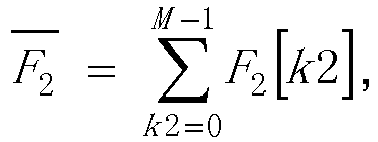
- 4): perform low-pass filtering on a number T of accumulated values F 1 and a number M of accumulated values F 2 thus obtained to get
F 1 andF 2:
- 5): construct two registers Buffer1 and Buffer2 with a length L, Buffer1 stores
F 1 calculated for recent L times, Buffer2 storesF 2 calculated for recent L times, initial values of Buffer1 and Buffer2 are both a number L of zeros, data in the Buffer1 is summed to obtain F 1_sum , and data in Buffer2 is summed to obtain F 2_sum . - The
argument acquisition module 24 is specifically configured to calculate the arguments ϕ 1 and ϕ 2 of the CD value of the data of the two polarization states according to F 1_sum and F 2_sum respectively:

- The
CD estimation module 25 is specifically configured to obtain a CD estimation coefficient ϕ 1" according to the arguments ϕ 1 and ϕ 2 of the CD value of the data of the two polarization states, and estimate the CD value CD according to the CD estimation coefficient ϕ 1":
- A position of the CD detection device for the optical transmission network in the optical transmission network is shown in
Fig. 3 . After an optical signal passes through an Optical Fibre Amplifier (Erbium-doped Optical Fibre Amplifier, EDFA), a hybrid optical amplifier, a Balanced Photodiode Detector (BPD), an Analogue-to-Digital Converter (ADC), an In-phase/Quadrature (IQ) balance, the data of the two polarization states orthogonal to each other is transmitted to the CD detection device (CD monitor) and CD compensation of the optical transmission network, the CD monitor sends the estimated CD value to the CD compensation, the CD compensation compensates for the CD value for other signal processing, and the optical signal is sent to a user-side interface after passing through a Forward Error Corrector (FEC) and a framer. - If being implemented in form of a software function module and sold or used as an independent product, the CD detection method for the optical transmission network according to the embodiments of the disclosure may also be stored in a computer-readable storage medium. Based on such an understanding, the technical solutions of the embodiments of the disclosure naturally or parts contributing to a conventional art may be embodied in form of a software product, and the computer software product is stored in a storage medium, including a plurality of instructions to enable a piece of computer equipment (which may be a personal computer, a server, network equipment or the like) to execute all or part of the method of each embodiment of the disclosure. The storage medium includes various media capable of storing program codes such as a U disk, a mobile hard disk, a Read-Only Memory (ROM), a magnetic disk or an optical disk. Therefore, the embodiments of the disclosure are not limited to any specific hardware and software combination.
- Correspondingly, the embodiments of the disclosure further provide a computer storage medium in which a computer program is stored for execution of the CD detection method for the optical transmission network according to the embodiments of the disclosure.
- What are described above are only the particular embodiments of the disclosure and not intended to limit the scope of protection of the disclosure. Any modifications, equivalent replacements, improvements and the like made within the spirit and principle of the disclosure shall fall within the scope of protection of the disclosure.
- From each embodiment of the disclosure, the data of the two polarization states orthogonal to each other is converted into the frequency-domain data and a linear combination operation is performed, the argument of the CD value of the data of the two polarization states are obtained, and the CD value is estimated according to the argument of the CD value. Therefore, electric domain estimation may be performed on CD of the optical transmission network to implement CD detection of the optical transmission network.
| Name | Range | Description |
| C | About 3 × 10⁸ m/s | Light velocity in optical fibre |
| N_fft | N | FFT transformation length |
| f | 32GHz, 28GHz and the like | Symbol rate |
| lambda | 1,529∼1,561 nm (C waveband) | Wavelength |
| 1,529∼1,568nm (CE waveband) | ||
| 1,570∼1,605nm (L waveband) |
Claims (13)
- A Chromatic Dispersion, CD, detection method for an optical transmission network comprising:converting data of two polarization states orthogonal to each other from time-domain data to frequency-domain data, performing extraction on the frequency-domain data and performing a linear combination operation on the extracted frequency-domain data, obtaining an argument of a CD value of the data of the two polarization states according to a result of the linear combination operation, and estimating the CD value according to the argument of the CD value of the data of the two polarization states.
- The CD detection method according to claim 1, wherein the converting the data of the two polarization states orthogonal to each other from the time-domain data to the frequency-domain data comprises: converting the data of the two polarization states orthogonal to each other from the time-domain data to the frequency-domain data by adopting a discrete Fourier transform, with N = 2 t and t being a natural number, and the frequency-domain data converted from the data of the two polarization states being set as X(k) and Y(k) respectively, k=0, 1, ..., N-1, then


- The CD detection method according to claim 2, wherein performing extraction on the frequency-domain data and performing the linear combination operation on the extracted frequency-domain data comprises: extracting data from the frequency-domain data according to the following rules:



- The CD detection method according to claim 3, wherein performing the linear combination operation on the extracted frequency-domain data comprises:step a: obtaining two groups of sequences X 1 (U), X 2 (U) and X 3 (U) as well as X1 (L), X 2 (L) and X 3 (L) in three different directions according to XU [k], XL [k], YU [k] and YL [k]:
 step b: performing conjugate multiplication on the two groups of sequences X 1 (U), X 2 (U) and X 3 (U) as well as X 1 (L), X 2 (L) and X 3 (L) to obtain a CD sub-sequence R 1[k], R 2[k] and R 3[k] in the three different directions:
 step c: setting a first interval value as Δ1 = 2 and a second interval value as Δ2 = 32, and calculating accumulated values F 1 and F 2 corresponding to these two interval values in different directions according to R 1[k], R 2[k] and R 3[k]:
 step d: performing low-pass filtering on a number T of accumulated values F 1 and a number M of accumulated values F 2 thus obtained to get
F 1 andF 2:
 step e: constructing two registers Buffer1 and Buffer2 with a length L, wherein Buffer1 stores
F 1 calculated for recent L times, Buffer2 storesF 2 calculated for recent L times, initial values of Buffer1 and Buffer2 are both a number L of zeros, data in the Buffer1 is summed to obtain F 1_sum , and data in Buffer2 is summed to obtain F 2_sum :

- The CD detection method according to claim 4, wherein obtaining the argument of the CD value of the data of the two polarization states according to the result of the linear combination operation comprises: calculating arguments ϕ 1 and ϕ 2 of the CD value of the data of the two polarization states according to F 1_sum and F 2_sum respectively:


- The CD detection method according to claim 5, wherein estimating the CD value according to the argument of the CD value of the data of the two polarization states comprises: obtaining a CD estimation coefficient ϕ 1" according to the arguments ϕ 1 and ϕ 2 of the CD value of the data of the two polarization states, and estimating the CD value CD according to the CD estimation coefficient ϕ 1":

- A Chromatic Dispersion, CD, detection device for an optical transmission network comprising: a data conversion module, a data extraction module, a linear combination operation module, an argument acquisition module and a CD estimation module, wherein
the data conversion module is configured to convert data of two polarization states orthogonal to each other from time-domain data to frequency-domain data;
the data extraction module is configured to perform extraction on the frequency-domain data, and send the extracted frequency-domain data to the linear combination operation module;
the linear combination operation module is configured to perform a linear combination operation on the extracted frequency-domain data, and send a result of the linear combination operation to the argument acquisition module;
the argument acquisition module is configured to obtain an argument of a CD value of the data of the two polarization states according to the result of the linear combination operation, and send the argument of the CD value to the CD estimation module; and
the CD estimation module is configured to estimate the CD value according to the argument of the CD value of the data of the two polarization states. - The CD detection device according to claim 7, wherein the data conversion module is configured to convert the data of the two polarization states to the frequency-domain data by adopting a discrete Fourier transform, with N = 2 t and t being a natural number, and the frequency-domain data converted from the data of the two polarization states being set as X(k) and Y(k) respectively, k=0, 1, ..., N-1, then


- The CD detection device according to claim 8, wherein the data extraction module is configured to extract data from the frequency-domain data according to the following rules:


- The CD detection device according to claim 9, wherein the linear combination operation module is configured to:1): obtain two groups of sequences X 1 (U), X 2 (U) and X 3 (U) as well as X 1 (L), X 2 (L) and X 3 (L) in three different directions according to XU [k], XL [k], YU [k] and YL [k]:
 2): perform conjugate multiplication on the two groups of sequences X 1 (U), X 2 (U) and X 3 (U) as well as X 1 (L), X 2 (L) and X 3 (L) to obtain a CD sub-sequence R 1[k], R 2[k] and R 3[k] in the three different directions:
 3): set a first interval value as Δ1 = 2 and a second interval value as Δ2 = 32, and calculate accumulated values F 1 and F 2 corresponding to these two interval values in different directions according to R 1[k], R 2[k] and R 3[k]:
 4): perform low-pass filtering on a number T of accumulated values F 1 and a number M of accumulated values F 2 thus obtained to get
F 1 andF 2:
 5): construct two registers Buffer1 and Buffer2 with a length L, wherein Buffer1 stores
F 1 calculated for recent L times, Buffer2 storesF 2 calculated for recent L times, initial values of Buffer1 and Buffer2 are both a number L of zeros, data in the Buffer1 is summed to obtain F1_sum , and data in Buffer2 is summed to obtain F 2_sum . - The CD detection device according to claim 10, wherein the argument acquisition module is configured to calculate CD arguments ϕ 1 and ϕ 2 of the data of the two polarization states according to F 1_sum and F 2_sum respectively:


- The CD detection device according to claim 11, wherein the CD estimation module is configured to obtain a CD estimation coefficient ϕ 1" according to the arguments ϕ 1 and ϕ 2 of the CD value of the data of the two polarization states, and estimate the CD value CD according to the CD estimation coefficient ϕ 1":

- A computer storage medium in which a computer program is stored for execution of the Chromatic Dispersion, CD, detection method for the optical transmission network according to any one of claims 1 to 6.
Applications Claiming Priority (2)
| Application Number | Priority Date | Filing Date | Title |
|---|---|---|---|
| CN201410421123.2A CN105375978B (en) | 2014-08-25 | 2014-08-25 | Dispersion detection method and device for optical transmission network |
| PCT/CN2015/076092 WO2016029696A1 (en) | 2014-08-25 | 2015-04-08 | Dispersion detection method and device in optical transmission network, and storage medium |
Publications (3)
| Publication Number | Publication Date |
|---|---|
| EP3190722A1 true EP3190722A1 (en) | 2017-07-12 |
| EP3190722A4 EP3190722A4 (en) | 2017-08-09 |
| EP3190722B1 EP3190722B1 (en) | 2020-06-24 |
Family
ID=55377820
Family Applications (1)
| Application Number | Title | Priority Date | Filing Date |
|---|---|---|---|
| EP15836728.4A Active EP3190722B1 (en) | 2014-08-25 | 2015-04-08 | Dispersion detection method and device in optical transmission network, and storage medium |
Country Status (4)
| Country | Link |
|---|---|
| US (1) | US10153847B2 (en) |
| EP (1) | EP3190722B1 (en) |
| CN (1) | CN105375978B (en) |
| WO (1) | WO2016029696A1 (en) |
Cited By (1)
| Publication number | Priority date | Publication date | Assignee | Title |
|---|---|---|---|---|
| EP3890211A4 (en) * | 2018-11-30 | 2022-01-19 | Sanechips Technology Co., Ltd. | Dispersion estimation method, device, receiver and storage medium |
Family Cites Families (21)
| Publication number | Priority date | Publication date | Assignee | Title |
|---|---|---|---|---|
| JP2002236078A (en) | 2001-02-07 | 2002-08-23 | Ando Electric Co Ltd | Device for measuring distribution of wavelength dispersion, and measuring method thereof |
| JP4282500B2 (en) | 2004-01-29 | 2009-06-24 | 株式会社東芝 | Structure inspection method and semiconductor device manufacturing method |
| US8160195B2 (en) * | 2007-11-02 | 2012-04-17 | The Texas A & M University System | Phase drift compensation for sampled signals |
| US8234549B2 (en) | 2008-03-06 | 2012-07-31 | Nec Laboratories America, Inc. | Simultaneous PMD compensation and chromatic dispersion compensation using LDPC coded OFDM |
| US20090324226A1 (en) | 2008-06-30 | 2009-12-31 | Fred Buchali | System, method and apparatus for channel estimation based on intra-symbol frequency domain averaging for coherent optical OFDM |
| CN101447834A (en) * | 2008-09-16 | 2009-06-03 | 北京邮电大学 | Electrical domain dispersion compensation method based on dispersion curve in WDM network |
| JP5168054B2 (en) | 2008-09-26 | 2013-03-21 | 富士通株式会社 | Chromatic dispersion compensation design system and chromatic dispersion compensation design method |
| CN101753217B (en) | 2008-11-28 | 2012-11-21 | 富士通株式会社 | Dispersion monitoring device and method, and dispersion compensation device |
| JP5577592B2 (en) | 2008-12-25 | 2014-08-27 | 住友電気工業株式会社 | Chromatic dispersion measuring apparatus and chromatic dispersion measuring method |
| JP5278001B2 (en) * | 2009-01-29 | 2013-09-04 | 富士通株式会社 | Optical communication system and optical receiver |
| US20110182582A1 (en) * | 2009-04-15 | 2011-07-28 | Nec Laboratories America Inc. | Joint sample rate conversion and cd compensation in frequency domain for coherent polmux |
| US8929750B2 (en) | 2009-05-18 | 2015-01-06 | Nippon Telegraph And Telephone Corporation | Signal generating circuit, optical signal transmitting apparatus, signal receiving circuit, method for establishing optical signal synchronization, and optical signal synchronization system |
| US8923707B2 (en) * | 2010-06-14 | 2014-12-30 | Infinera Corporation | Apparatus for compensating optical signal impairments |
| US8705986B2 (en) * | 2010-11-23 | 2014-04-22 | Infinera Corporation | PMD-insensitive method of chromatic dispersion estimation for a coherent receiver |
| JP5682633B2 (en) * | 2011-01-31 | 2015-03-11 | 富士通株式会社 | Optical transmitter and optical signal transmission method |
| CN102142905B (en) * | 2011-02-28 | 2013-12-04 | 华为技术有限公司 | Method and device for compensating chromatic dispersion in optical communication system |
| CN102324997B (en) * | 2011-06-29 | 2015-07-22 | 北京邮电大学 | Synchronization method of improved symbol in coherent light OFDM (Orthogonal Frequency Division Multiplexing) system |
| CN103430003B (en) * | 2012-02-01 | 2016-03-30 | 华为技术有限公司 | For estimating the method for the dispersion of the light signal received |
| WO2013185845A1 (en) | 2012-06-15 | 2013-12-19 | Huawei Technologies Co., Ltd. | Method for adapting an equalizer to equalize a composite characteristic of an optical communication channel |
| US9002215B2 (en) * | 2012-07-13 | 2015-04-07 | Oclaro, Inc. | Spectral analysis for coherent optical receivers |
| CN104780131B (en) * | 2014-01-15 | 2019-04-30 | 深圳市中兴微电子技术有限公司 | Chromatic dispersion measurement method, device and digital coherent receiver |
-
2014
- 2014-08-25 CN CN201410421123.2A patent/CN105375978B/en active Active
-
2015
- 2015-04-08 WO PCT/CN2015/076092 patent/WO2016029696A1/en not_active Ceased
- 2015-04-08 EP EP15836728.4A patent/EP3190722B1/en active Active
- 2015-04-08 US US15/506,105 patent/US10153847B2/en active Active
Cited By (1)
| Publication number | Priority date | Publication date | Assignee | Title |
|---|---|---|---|---|
| EP3890211A4 (en) * | 2018-11-30 | 2022-01-19 | Sanechips Technology Co., Ltd. | Dispersion estimation method, device, receiver and storage medium |
Also Published As
| Publication number | Publication date |
|---|---|
| EP3190722A4 (en) | 2017-08-09 |
| CN105375978B (en) | 2019-02-05 |
| CN105375978A (en) | 2016-03-02 |
| US10153847B2 (en) | 2018-12-11 |
| EP3190722B1 (en) | 2020-06-24 |
| WO2016029696A1 (en) | 2016-03-03 |
| US20180159635A1 (en) | 2018-06-07 |
Similar Documents
| Publication | Publication Date | Title |
|---|---|---|
| US11962344B2 (en) | Method and apparatus for obtaining transmitter test parameter, and storage medium | |
| US9859977B2 (en) | Method for estimating channel power, method for monitoring frequency spectrum characteristic, apparatus and system | |
| EP3096469B1 (en) | Chromatic dispersion measurement method and device and digital coherent receiver | |
| US10422719B2 (en) | Chromatic dispersion estimating circuit, optical reception device and chromatic dispersion amount estimating method | |
| EP3863195A1 (en) | Method and device for processing optical signal | |
| CN105519019B (en) | A method and device for detecting interference signals | |
| CN103138844B (en) | A kind of phase noise compensation method of 16QAM modulation signal | |
| WO2016173324A1 (en) | Optical signal to noise ratio monitoring method and device | |
| US9825699B2 (en) | Method and apparatus for correcting inter-channel power imbalance and receiver | |
| US8566073B2 (en) | Simulation device and simulation method | |
| CN112004263A (en) | Group delay fluctuation calibration method and device | |
| CN105991484A (en) | Frequency offset estimation method and frequency offset estimation device | |
| US9806922B2 (en) | Apparatus for estimating channel spacing, apparatus for monitoring wavelength, and receiver | |
| US10554379B2 (en) | Method for obtaining phase detection signal in clock recovery circuit and phase detector | |
| EP3190722B1 (en) | Dispersion detection method and device in optical transmission network, and storage medium | |
| CN103004110B (en) | The methods, devices and systems of dispersive estimates | |
| Kashef et al. | Non‐Gaussian statistics of CO‐OFDM signals after non‐linear optical fibre transmission | |
| CN114726702A (en) | Method and device for estimating and compensating channel frequency offset | |
| WO2015196744A1 (en) | Signal processing method and device used for active distribution network | |
| US9654156B2 (en) | Nonlinear compensating apparatus and method, transmitter and communication system | |
| CN106559133B (en) | Optical signal detection method and network device thereof | |
| CN114520757A (en) | Performance estimation device and method of nonlinear communication system and electronic equipment | |
| Wu et al. | A novel algorithm to mitigate the effect of clipping in orthogonal frequency division multiplexing underwater communication acoustic sensor system | |
| CN116192249A (en) | Dispersion estimation method, chip, electronic equipment and storage medium | |
| CN112804015B (en) | Channel phase calibration method, equipment, device and storage medium |
Legal Events
| Date | Code | Title | Description |
|---|---|---|---|
| STAA | Information on the status of an ep patent application or granted ep patent |
Free format text: STATUS: THE INTERNATIONAL PUBLICATION HAS BEEN MADE |
|
| PUAI | Public reference made under article 153(3) epc to a published international application that has entered the european phase |
Free format text: ORIGINAL CODE: 0009012 |
|
| STAA | Information on the status of an ep patent application or granted ep patent |
Free format text: STATUS: REQUEST FOR EXAMINATION WAS MADE |
|
| 17P | Request for examination filed |
Effective date: 20170228 |
|
| AK | Designated contracting states |
Kind code of ref document: A1 Designated state(s): AL AT BE BG CH CY CZ DE DK EE ES FI FR GB GR HR HU IE IS IT LI LT LU LV MC MK MT NL NO PL PT RO RS SE SI SK SM TR |
|
| AX | Request for extension of the european patent |
Extension state: BA ME |
|
| A4 | Supplementary search report drawn up and despatched |
Effective date: 20170706 |
|
| RIC1 | Information provided on ipc code assigned before grant |
Ipc: H04B 10/079 20130101ALI20170630BHEP Ipc: H04B 10/2513 20130101ALI20170630BHEP Ipc: H04B 10/07 20130101AFI20170630BHEP Ipc: H04B 10/61 20130101ALI20170630BHEP |
|
| DAV | Request for validation of the european patent (deleted) | ||
| DAX | Request for extension of the european patent (deleted) | ||
| GRAP | Despatch of communication of intention to grant a patent |
Free format text: ORIGINAL CODE: EPIDOSNIGR1 |
|
| STAA | Information on the status of an ep patent application or granted ep patent |
Free format text: STATUS: GRANT OF PATENT IS INTENDED |
|
| INTG | Intention to grant announced |
Effective date: 20200127 |
|
| GRAS | Grant fee paid |
Free format text: ORIGINAL CODE: EPIDOSNIGR3 |
|
| GRAA | (expected) grant |
Free format text: ORIGINAL CODE: 0009210 |
|
| STAA | Information on the status of an ep patent application or granted ep patent |
Free format text: STATUS: THE PATENT HAS BEEN GRANTED |
|
| AK | Designated contracting states |
Kind code of ref document: B1 Designated state(s): AL AT BE BG CH CY CZ DE DK EE ES FI FR GB GR HR HU IE IS IT LI LT LU LV MC MK MT NL NO PL PT RO RS SE SI SK SM TR |
|
| REG | Reference to a national code |
Ref country code: GB Ref legal event code: FG4D |
|
| REG | Reference to a national code |
Ref country code: CH Ref legal event code: EP |
|
| REG | Reference to a national code |
Ref country code: AT Ref legal event code: REF Ref document number: 1284937 Country of ref document: AT Kind code of ref document: T Effective date: 20200715 |
|
| REG | Reference to a national code |
Ref country code: DE Ref legal event code: R096 Ref document number: 602015054838 Country of ref document: DE |
|
| REG | Reference to a national code |
Ref country code: IE Ref legal event code: FG4D |
|
| PG25 | Lapsed in a contracting state [announced via postgrant information from national office to epo] |
Ref country code: LT Free format text: LAPSE BECAUSE OF FAILURE TO SUBMIT A TRANSLATION OF THE DESCRIPTION OR TO PAY THE FEE WITHIN THE PRESCRIBED TIME-LIMIT Effective date: 20200624 Ref country code: GR Free format text: LAPSE BECAUSE OF FAILURE TO SUBMIT A TRANSLATION OF THE DESCRIPTION OR TO PAY THE FEE WITHIN THE PRESCRIBED TIME-LIMIT Effective date: 20200925 Ref country code: FI Free format text: LAPSE BECAUSE OF FAILURE TO SUBMIT A TRANSLATION OF THE DESCRIPTION OR TO PAY THE FEE WITHIN THE PRESCRIBED TIME-LIMIT Effective date: 20200624 Ref country code: NO Free format text: LAPSE BECAUSE OF FAILURE TO SUBMIT A TRANSLATION OF THE DESCRIPTION OR TO PAY THE FEE WITHIN THE PRESCRIBED TIME-LIMIT Effective date: 20200924 Ref country code: SE Free format text: LAPSE BECAUSE OF FAILURE TO SUBMIT A TRANSLATION OF THE DESCRIPTION OR TO PAY THE FEE WITHIN THE PRESCRIBED TIME-LIMIT Effective date: 20200624 |
|
| REG | Reference to a national code |
Ref country code: LT Ref legal event code: MG4D |
|
| PG25 | Lapsed in a contracting state [announced via postgrant information from national office to epo] |
Ref country code: RS Free format text: LAPSE BECAUSE OF FAILURE TO SUBMIT A TRANSLATION OF THE DESCRIPTION OR TO PAY THE FEE WITHIN THE PRESCRIBED TIME-LIMIT Effective date: 20200624 Ref country code: HR Free format text: LAPSE BECAUSE OF FAILURE TO SUBMIT A TRANSLATION OF THE DESCRIPTION OR TO PAY THE FEE WITHIN THE PRESCRIBED TIME-LIMIT Effective date: 20200624 Ref country code: LV Free format text: LAPSE BECAUSE OF FAILURE TO SUBMIT A TRANSLATION OF THE DESCRIPTION OR TO PAY THE FEE WITHIN THE PRESCRIBED TIME-LIMIT Effective date: 20200624 Ref country code: BG Free format text: LAPSE BECAUSE OF FAILURE TO SUBMIT A TRANSLATION OF THE DESCRIPTION OR TO PAY THE FEE WITHIN THE PRESCRIBED TIME-LIMIT Effective date: 20200924 |
|
| REG | Reference to a national code |
Ref country code: NL Ref legal event code: MP Effective date: 20200624 |
|
| REG | Reference to a national code |
Ref country code: AT Ref legal event code: MK05 Ref document number: 1284937 Country of ref document: AT Kind code of ref document: T Effective date: 20200624 |
|
| PG25 | Lapsed in a contracting state [announced via postgrant information from national office to epo] |
Ref country code: AL Free format text: LAPSE BECAUSE OF FAILURE TO SUBMIT A TRANSLATION OF THE DESCRIPTION OR TO PAY THE FEE WITHIN THE PRESCRIBED TIME-LIMIT Effective date: 20200624 Ref country code: NL Free format text: LAPSE BECAUSE OF FAILURE TO SUBMIT A TRANSLATION OF THE DESCRIPTION OR TO PAY THE FEE WITHIN THE PRESCRIBED TIME-LIMIT Effective date: 20200624 |
|
| PG25 | Lapsed in a contracting state [announced via postgrant information from national office to epo] |
Ref country code: EE Free format text: LAPSE BECAUSE OF FAILURE TO SUBMIT A TRANSLATION OF THE DESCRIPTION OR TO PAY THE FEE WITHIN THE PRESCRIBED TIME-LIMIT Effective date: 20200624 Ref country code: SM Free format text: LAPSE BECAUSE OF FAILURE TO SUBMIT A TRANSLATION OF THE DESCRIPTION OR TO PAY THE FEE WITHIN THE PRESCRIBED TIME-LIMIT Effective date: 20200624 Ref country code: CZ Free format text: LAPSE BECAUSE OF FAILURE TO SUBMIT A TRANSLATION OF THE DESCRIPTION OR TO PAY THE FEE WITHIN THE PRESCRIBED TIME-LIMIT Effective date: 20200624 Ref country code: RO Free format text: LAPSE BECAUSE OF FAILURE TO SUBMIT A TRANSLATION OF THE DESCRIPTION OR TO PAY THE FEE WITHIN THE PRESCRIBED TIME-LIMIT Effective date: 20200624 Ref country code: ES Free format text: LAPSE BECAUSE OF FAILURE TO SUBMIT A TRANSLATION OF THE DESCRIPTION OR TO PAY THE FEE WITHIN THE PRESCRIBED TIME-LIMIT Effective date: 20200624 Ref country code: PT Free format text: LAPSE BECAUSE OF FAILURE TO SUBMIT A TRANSLATION OF THE DESCRIPTION OR TO PAY THE FEE WITHIN THE PRESCRIBED TIME-LIMIT Effective date: 20201026 Ref country code: AT Free format text: LAPSE BECAUSE OF FAILURE TO SUBMIT A TRANSLATION OF THE DESCRIPTION OR TO PAY THE FEE WITHIN THE PRESCRIBED TIME-LIMIT Effective date: 20200624 Ref country code: IT Free format text: LAPSE BECAUSE OF FAILURE TO SUBMIT A TRANSLATION OF THE DESCRIPTION OR TO PAY THE FEE WITHIN THE PRESCRIBED TIME-LIMIT Effective date: 20200624 |
|
| PG25 | Lapsed in a contracting state [announced via postgrant information from national office to epo] |
Ref country code: SK Free format text: LAPSE BECAUSE OF FAILURE TO SUBMIT A TRANSLATION OF THE DESCRIPTION OR TO PAY THE FEE WITHIN THE PRESCRIBED TIME-LIMIT Effective date: 20200624 Ref country code: PL Free format text: LAPSE BECAUSE OF FAILURE TO SUBMIT A TRANSLATION OF THE DESCRIPTION OR TO PAY THE FEE WITHIN THE PRESCRIBED TIME-LIMIT Effective date: 20200624 Ref country code: IS Free format text: LAPSE BECAUSE OF FAILURE TO SUBMIT A TRANSLATION OF THE DESCRIPTION OR TO PAY THE FEE WITHIN THE PRESCRIBED TIME-LIMIT Effective date: 20201024 |
|
| REG | Reference to a national code |
Ref country code: DE Ref legal event code: R097 Ref document number: 602015054838 Country of ref document: DE |
|
| PG25 | Lapsed in a contracting state [announced via postgrant information from national office to epo] |
Ref country code: DK Free format text: LAPSE BECAUSE OF FAILURE TO SUBMIT A TRANSLATION OF THE DESCRIPTION OR TO PAY THE FEE WITHIN THE PRESCRIBED TIME-LIMIT Effective date: 20200624 |
|
| PLBE | No opposition filed within time limit |
Free format text: ORIGINAL CODE: 0009261 |
|
| STAA | Information on the status of an ep patent application or granted ep patent |
Free format text: STATUS: NO OPPOSITION FILED WITHIN TIME LIMIT |
|
| 26N | No opposition filed |
Effective date: 20210325 |
|
| PG25 | Lapsed in a contracting state [announced via postgrant information from national office to epo] |
Ref country code: SI Free format text: LAPSE BECAUSE OF FAILURE TO SUBMIT A TRANSLATION OF THE DESCRIPTION OR TO PAY THE FEE WITHIN THE PRESCRIBED TIME-LIMIT Effective date: 20200624 |
|
| PG25 | Lapsed in a contracting state [announced via postgrant information from national office to epo] |
Ref country code: MC Free format text: LAPSE BECAUSE OF FAILURE TO SUBMIT A TRANSLATION OF THE DESCRIPTION OR TO PAY THE FEE WITHIN THE PRESCRIBED TIME-LIMIT Effective date: 20200624 |
|
| PG25 | Lapsed in a contracting state [announced via postgrant information from national office to epo] |
Ref country code: LU Free format text: LAPSE BECAUSE OF NON-PAYMENT OF DUE FEES Effective date: 20210408 |
|
| REG | Reference to a national code |
Ref country code: BE Ref legal event code: MM Effective date: 20210430 |
|
| PG25 | Lapsed in a contracting state [announced via postgrant information from national office to epo] |
Ref country code: LI Free format text: LAPSE BECAUSE OF NON-PAYMENT OF DUE FEES Effective date: 20210430 Ref country code: CH Free format text: LAPSE BECAUSE OF NON-PAYMENT OF DUE FEES Effective date: 20210430 |
|
| PG25 | Lapsed in a contracting state [announced via postgrant information from national office to epo] |
Ref country code: IE Free format text: LAPSE BECAUSE OF NON-PAYMENT OF DUE FEES Effective date: 20210408 |
|
| PG25 | Lapsed in a contracting state [announced via postgrant information from national office to epo] |
Ref country code: IS Free format text: LAPSE BECAUSE OF FAILURE TO SUBMIT A TRANSLATION OF THE DESCRIPTION OR TO PAY THE FEE WITHIN THE PRESCRIBED TIME-LIMIT Effective date: 20201024 |
|
| PG25 | Lapsed in a contracting state [announced via postgrant information from national office to epo] |
Ref country code: BE Free format text: LAPSE BECAUSE OF NON-PAYMENT OF DUE FEES Effective date: 20210430 |
|
| PG25 | Lapsed in a contracting state [announced via postgrant information from national office to epo] |
Ref country code: HU Free format text: LAPSE BECAUSE OF FAILURE TO SUBMIT A TRANSLATION OF THE DESCRIPTION OR TO PAY THE FEE WITHIN THE PRESCRIBED TIME-LIMIT; INVALID AB INITIO Effective date: 20150408 |
|
| PG25 | Lapsed in a contracting state [announced via postgrant information from national office to epo] |
Ref country code: CY Free format text: LAPSE BECAUSE OF FAILURE TO SUBMIT A TRANSLATION OF THE DESCRIPTION OR TO PAY THE FEE WITHIN THE PRESCRIBED TIME-LIMIT Effective date: 20200624 |
|
| PG25 | Lapsed in a contracting state [announced via postgrant information from national office to epo] |
Ref country code: MK Free format text: LAPSE BECAUSE OF FAILURE TO SUBMIT A TRANSLATION OF THE DESCRIPTION OR TO PAY THE FEE WITHIN THE PRESCRIBED TIME-LIMIT Effective date: 20200624 |
|
| PG25 | Lapsed in a contracting state [announced via postgrant information from national office to epo] |
Ref country code: MT Free format text: LAPSE BECAUSE OF FAILURE TO SUBMIT A TRANSLATION OF THE DESCRIPTION OR TO PAY THE FEE WITHIN THE PRESCRIBED TIME-LIMIT Effective date: 20200624 |
|
| PGFP | Annual fee paid to national office [announced via postgrant information from national office to epo] |
Ref country code: TR Payment date: 20250321 Year of fee payment: 11 |
|
| PGFP | Annual fee paid to national office [announced via postgrant information from national office to epo] |
Ref country code: DE Payment date: 20250305 Year of fee payment: 11 |
|
| PGFP | Annual fee paid to national office [announced via postgrant information from national office to epo] |
Ref country code: GB Payment date: 20260310 Year of fee payment: 12 |
|
| PGFP | Annual fee paid to national office [announced via postgrant information from national office to epo] |
Ref country code: FR Payment date: 20260309 Year of fee payment: 12 |