EP3190625A1 - Semiconductor structure and fabrication method thereof - Google Patents
Semiconductor structure and fabrication method thereof Download PDFInfo
- Publication number
- EP3190625A1 EP3190625A1 EP16207265.6A EP16207265A EP3190625A1 EP 3190625 A1 EP3190625 A1 EP 3190625A1 EP 16207265 A EP16207265 A EP 16207265A EP 3190625 A1 EP3190625 A1 EP 3190625A1
- Authority
- EP
- European Patent Office
- Prior art keywords
- layer
- covering layer
- covering
- stress
- transistor region
- Prior art date
- Legal status (The legal status is an assumption and is not a legal conclusion. Google has not performed a legal analysis and makes no representation as to the accuracy of the status listed.)
- Withdrawn
Links
Images




Classifications
-
- H—ELECTRICITY
- H10—SEMICONDUCTOR DEVICES; ELECTRIC SOLID-STATE DEVICES NOT OTHERWISE PROVIDED FOR
- H10D—INORGANIC ELECTRIC SEMICONDUCTOR DEVICES
- H10D30/00—Field-effect transistors [FET]
- H10D30/60—Insulated-gate field-effect transistors [IGFET]
- H10D30/791—Arrangements for exerting mechanical stress on the crystal lattice of the channel regions
- H10D30/797—Arrangements for exerting mechanical stress on the crystal lattice of the channel regions being in source or drain regions, e.g. SiGe source or drain
-
- H—ELECTRICITY
- H10—SEMICONDUCTOR DEVICES; ELECTRIC SOLID-STATE DEVICES NOT OTHERWISE PROVIDED FOR
- H10D—INORGANIC ELECTRIC SEMICONDUCTOR DEVICES
- H10D30/00—Field-effect transistors [FET]
- H10D30/60—Insulated-gate field-effect transistors [IGFET]
- H10D30/62—Fin field-effect transistors [FinFET]
- H10D30/6219—Fin field-effect transistors [FinFET] characterised by the source or drain electrodes
-
- H—ELECTRICITY
- H10—SEMICONDUCTOR DEVICES; ELECTRIC SOLID-STATE DEVICES NOT OTHERWISE PROVIDED FOR
- H10D—INORGANIC ELECTRIC SEMICONDUCTOR DEVICES
- H10D62/00—Semiconductor bodies, or regions thereof, of devices having potential barriers
- H10D62/01—Manufacture or treatment
- H10D62/021—Forming source or drain recesses by etching e.g. recessing by etching and then refilling
-
- H—ELECTRICITY
- H10—SEMICONDUCTOR DEVICES; ELECTRIC SOLID-STATE DEVICES NOT OTHERWISE PROVIDED FOR
- H10D—INORGANIC ELECTRIC SEMICONDUCTOR DEVICES
- H10D62/00—Semiconductor bodies, or regions thereof, of devices having potential barriers
- H10D62/10—Shapes, relative sizes or dispositions of the regions of the semiconductor bodies; Shapes of the semiconductor bodies
- H10D62/113—Isolations within a component, i.e. internal isolations
- H10D62/115—Dielectric isolations, e.g. air gaps
-
- H—ELECTRICITY
- H10—SEMICONDUCTOR DEVICES; ELECTRIC SOLID-STATE DEVICES NOT OTHERWISE PROVIDED FOR
- H10D—INORGANIC ELECTRIC SEMICONDUCTOR DEVICES
- H10D62/00—Semiconductor bodies, or regions thereof, of devices having potential barriers
- H10D62/10—Shapes, relative sizes or dispositions of the regions of the semiconductor bodies; Shapes of the semiconductor bodies
- H10D62/13—Semiconductor regions connected to electrodes carrying current to be rectified, amplified or switched, e.g. source or drain regions
- H10D62/149—Source or drain regions of field-effect devices
- H10D62/151—Source or drain regions of field-effect devices of IGFETs
-
- H—ELECTRICITY
- H10—SEMICONDUCTOR DEVICES; ELECTRIC SOLID-STATE DEVICES NOT OTHERWISE PROVIDED FOR
- H10D—INORGANIC ELECTRIC SEMICONDUCTOR DEVICES
- H10D62/00—Semiconductor bodies, or regions thereof, of devices having potential barriers
- H10D62/10—Shapes, relative sizes or dispositions of the regions of the semiconductor bodies; Shapes of the semiconductor bodies
- H10D62/17—Semiconductor regions connected to electrodes not carrying current to be rectified, amplified or switched, e.g. channel regions
- H10D62/351—Substrate regions of field-effect devices
- H10D62/357—Substrate regions of field-effect devices of FETs
- H10D62/364—Substrate regions of field-effect devices of FETs of IGFETs
-
- H—ELECTRICITY
- H10—SEMICONDUCTOR DEVICES; ELECTRIC SOLID-STATE DEVICES NOT OTHERWISE PROVIDED FOR
- H10D—INORGANIC ELECTRIC SEMICONDUCTOR DEVICES
- H10D62/00—Semiconductor bodies, or regions thereof, of devices having potential barriers
- H10D62/80—Semiconductor bodies, or regions thereof, of devices having potential barriers characterised by the materials
- H10D62/82—Heterojunctions
- H10D62/822—Heterojunctions comprising only Group IV materials heterojunctions, e.g. Si/Ge heterojunctions
-
- H—ELECTRICITY
- H10—SEMICONDUCTOR DEVICES; ELECTRIC SOLID-STATE DEVICES NOT OTHERWISE PROVIDED FOR
- H10D—INORGANIC ELECTRIC SEMICONDUCTOR DEVICES
- H10D84/00—Integrated devices formed in or on semiconductor substrates that comprise only semiconducting layers, e.g. on Si wafers or on GaAs-on-Si wafers
- H10D84/01—Manufacture or treatment
- H10D84/0123—Integrating together multiple components covered by H10D12/00 or H10D30/00, e.g. integrating multiple IGBTs
- H10D84/0126—Integrating together multiple components covered by H10D12/00 or H10D30/00, e.g. integrating multiple IGBTs the components including insulated gates, e.g. IGFETs
- H10D84/013—Manufacturing their source or drain regions, e.g. silicided source or drain regions
-
- H—ELECTRICITY
- H10—SEMICONDUCTOR DEVICES; ELECTRIC SOLID-STATE DEVICES NOT OTHERWISE PROVIDED FOR
- H10D—INORGANIC ELECTRIC SEMICONDUCTOR DEVICES
- H10D84/00—Integrated devices formed in or on semiconductor substrates that comprise only semiconducting layers, e.g. on Si wafers or on GaAs-on-Si wafers
- H10D84/01—Manufacture or treatment
- H10D84/0123—Integrating together multiple components covered by H10D12/00 or H10D30/00, e.g. integrating multiple IGBTs
- H10D84/0126—Integrating together multiple components covered by H10D12/00 or H10D30/00, e.g. integrating multiple IGBTs the components including insulated gates, e.g. IGFETs
- H10D84/0151—Manufacturing their isolation regions
-
- H—ELECTRICITY
- H10—SEMICONDUCTOR DEVICES; ELECTRIC SOLID-STATE DEVICES NOT OTHERWISE PROVIDED FOR
- H10D—INORGANIC ELECTRIC SEMICONDUCTOR DEVICES
- H10D84/00—Integrated devices formed in or on semiconductor substrates that comprise only semiconducting layers, e.g. on Si wafers or on GaAs-on-Si wafers
- H10D84/01—Manufacture or treatment
- H10D84/0123—Integrating together multiple components covered by H10D12/00 or H10D30/00, e.g. integrating multiple IGBTs
- H10D84/0126—Integrating together multiple components covered by H10D12/00 or H10D30/00, e.g. integrating multiple IGBTs the components including insulated gates, e.g. IGFETs
- H10D84/0158—Integrating together multiple components covered by H10D12/00 or H10D30/00, e.g. integrating multiple IGBTs the components including insulated gates, e.g. IGFETs the components including FinFETs
-
- H—ELECTRICITY
- H10—SEMICONDUCTOR DEVICES; ELECTRIC SOLID-STATE DEVICES NOT OTHERWISE PROVIDED FOR
- H10D—INORGANIC ELECTRIC SEMICONDUCTOR DEVICES
- H10D84/00—Integrated devices formed in or on semiconductor substrates that comprise only semiconducting layers, e.g. on Si wafers or on GaAs-on-Si wafers
- H10D84/01—Manufacture or treatment
- H10D84/0123—Integrating together multiple components covered by H10D12/00 or H10D30/00, e.g. integrating multiple IGBTs
- H10D84/0126—Integrating together multiple components covered by H10D12/00 or H10D30/00, e.g. integrating multiple IGBTs the components including insulated gates, e.g. IGFETs
- H10D84/0165—Integrating together multiple components covered by H10D12/00 or H10D30/00, e.g. integrating multiple IGBTs the components including insulated gates, e.g. IGFETs the components including complementary IGFETs, e.g. CMOS devices
- H10D84/0193—Integrating together multiple components covered by H10D12/00 or H10D30/00, e.g. integrating multiple IGBTs the components including insulated gates, e.g. IGFETs the components including complementary IGFETs, e.g. CMOS devices the components including FinFETs
-
- H—ELECTRICITY
- H10—SEMICONDUCTOR DEVICES; ELECTRIC SOLID-STATE DEVICES NOT OTHERWISE PROVIDED FOR
- H10D—INORGANIC ELECTRIC SEMICONDUCTOR DEVICES
- H10D84/00—Integrated devices formed in or on semiconductor substrates that comprise only semiconducting layers, e.g. on Si wafers or on GaAs-on-Si wafers
- H10D84/01—Manufacture or treatment
- H10D84/02—Manufacture or treatment characterised by using material-based technologies
- H10D84/03—Manufacture or treatment characterised by using material-based technologies using Group IV technology, e.g. silicon technology or silicon-carbide [SiC] technology
- H10D84/038—Manufacture or treatment characterised by using material-based technologies using Group IV technology, e.g. silicon technology or silicon-carbide [SiC] technology using silicon technology, e.g. SiGe
-
- H—ELECTRICITY
- H10—SEMICONDUCTOR DEVICES; ELECTRIC SOLID-STATE DEVICES NOT OTHERWISE PROVIDED FOR
- H10D—INORGANIC ELECTRIC SEMICONDUCTOR DEVICES
- H10D84/00—Integrated devices formed in or on semiconductor substrates that comprise only semiconducting layers, e.g. on Si wafers or on GaAs-on-Si wafers
- H10D84/80—Integrated devices formed in or on semiconductor substrates that comprise only semiconducting layers, e.g. on Si wafers or on GaAs-on-Si wafers characterised by the integration of at least one component covered by groups H10D12/00 or H10D30/00, e.g. integration of IGFETs
- H10D84/82—Integrated devices formed in or on semiconductor substrates that comprise only semiconducting layers, e.g. on Si wafers or on GaAs-on-Si wafers characterised by the integration of at least one component covered by groups H10D12/00 or H10D30/00, e.g. integration of IGFETs of only field-effect components
- H10D84/83—Integrated devices formed in or on semiconductor substrates that comprise only semiconducting layers, e.g. on Si wafers or on GaAs-on-Si wafers characterised by the integration of at least one component covered by groups H10D12/00 or H10D30/00, e.g. integration of IGFETs of only field-effect components of only insulated-gate FETs [IGFET]
- H10D84/834—Integrated devices formed in or on semiconductor substrates that comprise only semiconducting layers, e.g. on Si wafers or on GaAs-on-Si wafers characterised by the integration of at least one component covered by groups H10D12/00 or H10D30/00, e.g. integration of IGFETs of only field-effect components of only insulated-gate FETs [IGFET] comprising FinFETs
-
- H—ELECTRICITY
- H10—SEMICONDUCTOR DEVICES; ELECTRIC SOLID-STATE DEVICES NOT OTHERWISE PROVIDED FOR
- H10P—GENERIC PROCESSES OR APPARATUS FOR THE MANUFACTURE OR TREATMENT OF DEVICES COVERED BY CLASS H10
- H10P14/00—Formation of materials, e.g. in the shape of layers or pillars
- H10P14/20—Formation of materials, e.g. in the shape of layers or pillars of semiconductor materials
- H10P14/34—Deposited materials, e.g. layers
- H10P14/3402—Deposited materials, e.g. layers characterised by the chemical composition
- H10P14/3404—Deposited materials, e.g. layers characterised by the chemical composition being Group IVA materials
- H10P14/3411—Silicon, silicon germanium or germanium
-
- H—ELECTRICITY
- H10—SEMICONDUCTOR DEVICES; ELECTRIC SOLID-STATE DEVICES NOT OTHERWISE PROVIDED FOR
- H10P—GENERIC PROCESSES OR APPARATUS FOR THE MANUFACTURE OR TREATMENT OF DEVICES COVERED BY CLASS H10
- H10P14/00—Formation of materials, e.g. in the shape of layers or pillars
- H10P14/60—Formation of materials, e.g. in the shape of layers or pillars of insulating materials
- H10P14/63—Formation of materials, e.g. in the shape of layers or pillars of insulating materials characterised by the formation processes
- H10P14/6326—Deposition processes
- H10P14/6328—Deposition from the gas or vapour phase
- H10P14/6334—Deposition from the gas or vapour phase using decomposition or reaction of gaseous or vapour phase compounds, i.e. chemical vapour deposition
-
- H—ELECTRICITY
- H10—SEMICONDUCTOR DEVICES; ELECTRIC SOLID-STATE DEVICES NOT OTHERWISE PROVIDED FOR
- H10P—GENERIC PROCESSES OR APPARATUS FOR THE MANUFACTURE OR TREATMENT OF DEVICES COVERED BY CLASS H10
- H10P14/00—Formation of materials, e.g. in the shape of layers or pillars
- H10P14/60—Formation of materials, e.g. in the shape of layers or pillars of insulating materials
- H10P14/69—Inorganic materials
- H10P14/692—Inorganic materials composed of oxides, glassy oxides or oxide-based glasses
- H10P14/6921—Inorganic materials composed of oxides, glassy oxides or oxide-based glasses containing silicon
- H10P14/6922—Inorganic materials composed of oxides, glassy oxides or oxide-based glasses containing silicon the material containing Si, O and at least one of H, N, C, F or other non-metal elements, e.g. SiOC, SiOC:H or SiONC
- H10P14/6923—Inorganic materials composed of oxides, glassy oxides or oxide-based glasses containing silicon the material containing Si, O and at least one of H, N, C, F or other non-metal elements, e.g. SiOC, SiOC:H or SiONC the material being boron or phosphorus doped silicon oxides, e.g. BPSG, BSG or PSG
-
- H—ELECTRICITY
- H10—SEMICONDUCTOR DEVICES; ELECTRIC SOLID-STATE DEVICES NOT OTHERWISE PROVIDED FOR
- H10P—GENERIC PROCESSES OR APPARATUS FOR THE MANUFACTURE OR TREATMENT OF DEVICES COVERED BY CLASS H10
- H10P50/00—Etching of wafers, substrates or parts of devices
- H10P50/20—Dry etching; Plasma etching; Reactive-ion etching
- H10P50/28—Dry etching; Plasma etching; Reactive-ion etching of insulating materials
- H10P50/282—Dry etching; Plasma etching; Reactive-ion etching of insulating materials of inorganic materials
- H10P50/283—Dry etching; Plasma etching; Reactive-ion etching of insulating materials of inorganic materials by chemical means
-
- H—ELECTRICITY
- H10—SEMICONDUCTOR DEVICES; ELECTRIC SOLID-STATE DEVICES NOT OTHERWISE PROVIDED FOR
- H10P—GENERIC PROCESSES OR APPARATUS FOR THE MANUFACTURE OR TREATMENT OF DEVICES COVERED BY CLASS H10
- H10P50/00—Etching of wafers, substrates or parts of devices
- H10P50/69—Etching of wafers, substrates or parts of devices using masks for semiconductor materials
- H10P50/691—Etching of wafers, substrates or parts of devices using masks for semiconductor materials for Group V materials or Group III-V materials
-
- H—ELECTRICITY
- H10—SEMICONDUCTOR DEVICES; ELECTRIC SOLID-STATE DEVICES NOT OTHERWISE PROVIDED FOR
- H10W—GENERIC PACKAGES, INTERCONNECTIONS, CONNECTORS OR OTHER CONSTRUCTIONAL DETAILS OF DEVICES COVERED BY CLASS H10
- H10W10/00—Isolation regions in semiconductor bodies between components of integrated devices
- H10W10/01—Manufacture or treatment
- H10W10/011—Manufacture or treatment of isolation regions comprising dielectric materials
- H10W10/014—Manufacture or treatment of isolation regions comprising dielectric materials using trench refilling with dielectric materials, e.g. shallow trench isolations
-
- H—ELECTRICITY
- H10—SEMICONDUCTOR DEVICES; ELECTRIC SOLID-STATE DEVICES NOT OTHERWISE PROVIDED FOR
- H10W—GENERIC PACKAGES, INTERCONNECTIONS, CONNECTORS OR OTHER CONSTRUCTIONAL DETAILS OF DEVICES COVERED BY CLASS H10
- H10W10/00—Isolation regions in semiconductor bodies between components of integrated devices
- H10W10/10—Isolation regions comprising dielectric materials
- H10W10/17—Isolation regions comprising dielectric materials formed using trench refilling with dielectric materials, e.g. shallow trench isolations
Definitions
- the present invention generally relates to the field of semiconductor manufacturing technology and, more particularly, relates to semiconductor structures and fabrication techniques thereof.
- semiconductor devices are developed toward the direction of higher component densities and integration degrees.
- the density of transistors is continuously increasing while the space among transistors is decreasing.
- the fabrication method of semiconductor structures should include forming a metal silicide on the formed crystal layer.
- the metal silicide is formed by first forming a covering layer on the formed crystal layer and then forming a metal layer on the covering layer.
- the metal ions in the metal layer can diffuse into the covering layer to form the metal silicide.
- semiconductor devices made by such current technologies tend to cause short-circuit among different devices in the formed semiconductor structure, leading to malfunction of the semiconductor devices.
- the disclosed device structures and methods are directed to solve one or more problems set forth above and other problems.
- a first aspect of the present invention includes a method for fabricating a semiconductor structure.
- the method includes providing a base having a first transistor region and a second transistor region adjacent to the first transistor region; and forming a first stress layer in the first transistor region and a second stress layer in the second transistor region, with the first stress layer and the second stress layer exposing part of a surface of the base.
- the method also includes forming a first covering layer on a surface of the first stress layer and a second covering layer on a surface of the second stress layer by epitaxial growth, with a gap between the first covering layer and the second covering layer exposing the surface of the base, and the neighboring side walls of the first covering layer and the second covering layer have vertices pointing to each other; forming an isolation layer filling up the gap, and a surface of the isolation layer is higher than the vertices, exposing top surfaces of the first covering layer and the second covering layer; and forming a third covering layer on the first covering layer and a fourth covering layer on the second covering layer by epitaxial growth.
- Forming an isolation layer filling up the gap may further include: forming an initial isolation layer covering the first covering layer and the second covering layer and filling up the gap; and removing the initial isolation layer that is on the top surfaces of the first covering layer and the second covering layer while retaining the initial isolation layer filling up the gap to form the isolation layer.
- the initial isolation layer is formed by using a fluid chemical vapor deposition process.
- the initial isolation layer may be removed by wet etching or dry etching.
- the base may include a substrate and an isolation structure between the first transistor region and the second transistor region.
- Forming a first stress layer in the first transistor region and a second stress layer in the second transistor region may further includes: forming a mask layer on the surface of the base, exposing the base within the first transistor region and the second transistor region, and the isolation structure surface between the first transistor region and the second transistor region; etching the base using the mask layer as a mask to form a first trench in the first transistor region and a second trench in the second transistor region; and forming the first stress layer in the first trench and the second stress layer in the second trench.
- the surface of the isolation layer may be at a same level as the top surfaces of the first covering layer and the second covering layer when forming the initial isolation layer.
- a thickness of the third covering layer and the fourth covering layer is in a range of approximately 30 ⁇ 100 ⁇ .
- the isolation layer may be made of deep ultraviolet absorbing oxide, borophosphosilicate glass, or phosphosilicate glass.
- a thickness of the isolation layer is in a range of approximately 10 ⁇ 500 ⁇ .
- a thickness of the first covering layer and the second covering layer is in a range of approximately 10 ⁇ 200 ⁇ .
- a width of the base between the first stress layer and the second stress layer in a range of approximately 28 nm ⁇ 1 ⁇ m.
- the first covering layer, the second covering layer, the third covering layer, and the fourth covering layer are made of a same material.
- the first covering layer, the second covering layer, the third covering layer, and the fourth covering layer are made of silicon germanium.
- a second aspect of the present invention includes a semiconductor structure.
- the semiconductor structure includes a base having a first transistor region and a second transistor region; a first stress layer in the first transistor region and a second stress layer in the second transistor region of the base, wherein the base is exposed by the first stress layer and the second stress layer; a first covering layer and a second covering layer formed on surfaces of the first stress layer and the second stress layer, respectively, and side walls of the first covering layer and the second covering layer have vertices pointing to each other; an isolation layer between the first covering layer and the second covering layer, and a top surface of the isolation layer is higher than the vertices, exposing the surfaces of the first covering layer and the second covering layer; and a third covering layer and a fourth covering layer formed on the surfaces of the first covering layer and the second covering layer, respectively.
- the surface of the isolation layer is at a same level with the surfaces of the first covering layer and the second covering layer.
- a thickness of the third covering layer and the fourth covering layer is in a range of approximately 30 ⁇ 100 ⁇ .
- a width of the base between the first stress layer and the second stress layer is in a range of approximately 28 nm ⁇ 1 ⁇ m.
- a thickness of the first covering layer and the second covering layer is in a range of approximately 10 ⁇ 200 ⁇ .
- a thickness of the isolation layer between the first covering layer and the second covering layer is in a range of approximately 10 ⁇ 500 ⁇ .
- the isolation layer is made of deep ultraviolet absorbing oxide, borophosphosilicate glass, or phosphosilicate glass.
- the first covering layer, the second covering layer, the third covering layer, and the fourth covering layer are made of a same material.
- Figures 1 ⁇ 3 show a semiconductor structure corresponding to an existing fabrication process.
- a base 100 containing a first transistor region "a" and an adjacent second transistor region “b” is provided.
- the base 100 includes a substrate 101 and an isolation structure 102.
- the substrate 101 contains two fin portions, a first fin portion and a second fin portion.
- the isolation structure 102 is formed on the substrate 101 and is around the first fin portion and the second fin portion. The top surfaces of the first fin portion and the second fin portion are exposed.
- the substrate 101 is then etched, forming a first trench 103 in the first transistor region "a" and a second trench 104 in the second transistor region "b".
- the fabrication method further includes forming a first gate structure and a second gate structure in the first transistor region "a" and the second transistor region “b" of the base 100, respectively.
- the substrate 101 under the first gate structure and the second gate structure forms the first channel and the second channel, respectively.
- a first stress layer 111 is formed in the first trench 103 ( Figure 1 ) of the first transistor region "a"
- a second stress layer 112 is formed in the second trench 104 ( Figure 1 ) of the second transistor region "b”.
- a first covering layer 121 that covers the first stress layer 111 is formed in the first transistor region "a"
- a second covering layer 122 that covers the second stress layer 112 is formed in the second transistor region "b”.
- the first covering layer 121 and the second covering layer 122 can be formed via epitaxial growth.
- the first covering layer 121 and the second covering layer 122 are used to form the metal silicide.
- the isolation structure 101 around the first trench 103 and the second trench 104 is also etched, forming a depressed area in the isolation structure 102.
- the surface of the first channel is higher than the surface of the isolation structure 102 between the first fin portion and the second fin portion
- the surface of the second channel is higher than the surface of the isolation structure 102 between the first fin portion and the second fin portion.
- the top surface of the first stress layer 111 should be higher than or at the same level with the surface of the first channel, and the surface of the second stress layer 112 should be higher than or at the same level with the surface of the second channel.
- the first stress layer 111 and the second stress layer 112 may protrude from the surface of the isolation structure 102.
- the growth directions of the first covering layer 121 and the second covering layer 122 are not limited, and the growth rates of the crystal forming the first covering layer 121 and the second covering layer 122 are different along different directions.
- vertices can easily form along the faster growth directions of the first covering layer 121 and the second covering layer 122.
- the first covering layer 121 and the second covering layer 122 can easily contact with each other at the vertices, causing the subsequently formed metal silicide short-circuited.
- the present invention provides an improved fabrication process and semiconductor structures thereof. According to the disclosed semiconductor structures and methods, the short-circuit problem and other problems may be overcome by, for example, forming an isolation layer and additional covering layers.
- the first covering layer that covers the first stress layer and the second covering layer that covers the second stress layer are formed.
- the first covering layer and the second covering layer are used to provide crystalline seeds for the subsequently formed third covering layer and forth covering layer, so that the crystallographic orientations of the third covering layer and the fourth covering layer are the same with the crystallographic orientations of the first covering layer and the second covering layer.
- an isolation layer filling up the gap between the first covering layer and the second covering layer is formed. The surface of the isolation layer is higher than the vertices of the first covering layer and the second covering layer.
- the growth directions of the third covering layer and the fourth covering layer are limited during the epitaxial growth process of forming the third covering layer and the fourth covering layer.
- the third covering layer and the fourth covering layer do not form at the vertices of the first covering layer and the second covering layer, and the contact between the third covering layer and the fourth covering layer is avoided.
- the contact between the metal silicide in the first transistor region and the second transistor region is also avoided, and the electrical insulation among different semiconductor devices can be achieved.
- the disclosed invention also provides a semiconductor structure.
- an isolation layer is between the first covering layer and the second covering layer.
- the surface of the isolation layer is higher than the vertices of the first covering layer and the second covering layer, and the vertices are not covered by the third covering layer or the fourth covering layer.
- the contact between the third covering layer and the fourth covering layer can be avoided.
- the first covering layer and the second covering layer are relatively thin and, therefore, it may be difficult for the first covering layer and the second covering layer to contact with each other.
- Figure 12 illustrates an exemplary fabrication process of a semiconductor structure consistent with the disclosed embodiments; and Figures 4 ⁇ 10 illustrate semiconductor structures corresponding to certain stages of the exemplary fabrication process.
- FIG. 12 As shown in Figure 12 , at the beginning of the fabrication process, a base is provided (S101).
- Figure 4 illustrates a corresponding semiconductor structure.
- a base 200 containing a first transistor region I and a second transistor region II is provided.
- the first transistor region I and the second transistor region II are used to form a fin-field effect transistor (Fin-FET).
- Fin-FET fin-field effect transistor
- the first transistor region I and the second transistor region II can also be used to form a planar transistor or other semiconductor device.
- the base 200 may include a substrate 201 and an isolation structure 202 on the substrate 201.
- the substrate 201 may contain a first fin portion 201 a in the first transistor region I and a second fin portion 201b in the second transistor region II.
- the side walls of the first fin portion 201 a and the second fin portion 201 b are covered by the isolation structure 202, and the top surfaces of the first fin portion 201a and the second fin portion 201b are exposed.
- the first fin portion 201a and the second fin portion 201b are used to form the drain and/or source region(s) of the Fin-FET.
- the substrate 201 is made of silicon. In other embodiments, the substrate 201 can also be made of any other appropriate semiconductor material, such as germanium, silicon germanium or silicon on an insulator.
- the isolation structure 202 is a shallow trench isolation structure, and the isolation structure 202 may be made of silicon oxide. In other embodiments, the isolation structure 202 can also be silicon nitride or silicon oxynitride.
- a first stress layer may be formed in the first transistor region I of the base 200 and a second stress layer may be formed in the second transistor region II of the base 200.
- the surface of the base 200 may be exposed by the first stress layer and the second stress layer.
- the first stress layer and the second stress layer may be used to provide corresponding stress for channels of the transistor.
- a first gate structure may be formed in the first transistor region I of the base 200 and a second gate structure may be formed in the second transistor region II of the base 200.
- the substrate 201 under the first gate structure forms the first channel
- the substrate 201 under the second gate structure forms the second channel.
- the first stress layer is in the first fin portion 201 a on the sides of the first gate structure
- the second stress layer is in the second fin portion 201b on the sides of the second gate structure.
- a first trench may be formed in the first transistor region of the base and a second trench may be formed in the second transistor region of the base (S102).
- Figure 5 illustrates a corresponding semiconductor structure.
- a first trench 203 may be formed in the first transistor region I of the base 200 and a second trench 204 may be formed in the second transistor region II of the base 200.
- a mask layer may be first formed on the surface of the base 200.
- the surface of the base 200 in the first transistor region I, the surface of the base 200 in the second transistor region II, and the surface of the isolation structure 202 between the first transistor region I and the second transistor region II may be exposed by the mask layer.
- the surface of the first fin portion 201a, the surface of the second fin portion 201b, and the surface of the isolation structure 202 between the surface of the first fin portion 201a and the surface of the second fin portion 201b are exposed by the mask layer.
- the mask layer may be made of a material different from the material of the substrate 201 and the isolation structure 202.
- the mask layer is made of silicon nitride.
- the base 200 may then be etched using the mask layer as a mask.
- the first trench 203 is then formed in the first transistor region I, and the second trench 204 is formed in the second transistor region II.
- the first fin portion 201a is etched to form the first trench 203 and the second fin portion 201b is etched to form the second trench 204.
- the isolation structure 202 around the first trench 203 and the second trench 204 may also be etched, forming a depressed area in the isolation structure 202, which may cause the surface of subsequently-formed first channel higher than the surface of the isolation structure 202 between the first fin portion 201a and the second fin portion 201b, and cause the surface of the second channel higher than the surface of the isolation structure 202 between the first fin portion 201 a and the second fin portion 201b.
- the first trench 203 and the second trench 204 are formed by dry etching the first fin portion 201 a and the second fin portion 201b.
- the first fin portion 201 a and the second fin portion 201 b can also be etched using a wet-etching method or using the combination of the dry and wet etching methods.
- the distance from the highest point of the isolation structure 202 between the first fin portion 201 a and the second fin portion 201b to the bottom of the first trench 203 may form the depth 'h1' of the first trench 203.
- the distance from the highest point of the isolation structure 202 between the first fin portion 201 a and the second fin portion 201b to the bottom of the second trench 204 may form the depth 'h2' of the second trench 204.
- the isolation structure 202 around the first trench 203 and the second trench 204 is also etched.
- the depths h1 of the first trench 203 and the depth h2 of the second trench 204 are 50 ⁇ 100 ⁇ .
- a first stress layer may be formed in the first trench of the base and a second stress layer may be formed in the second trench of the base (S103).
- Figure 6 illustrates a corresponding semiconductor structure.
- a first stress layer 211 is then formed in the first trench 203 ( Figure 5 ), and a second stress layer 212 is formed in the second trench 204 ( Figure 5 ).
- the surface of the first channel is higher than the surface of the isolation structure 202 between the first fin portion 201a and the second fin portion 201b.
- the top surface of the first stress layer 211 may be higher than the surface of the first channel or at the same level with the surface of the first channel.
- the thickness of the first stress layer 211 is larger than the depth h1 of the first trench 203, causing the first stress layer 211 to protrude from the surface of the isolation structure 202.
- the surface of the second channel is higher than the surface of the isolation structure 202 between the first fin portion 201 a and the second fin portion 201b.
- the top surface of the second stress layer 212 may be higher than the surface of the second channel or at the same level with the surface of the second channel.
- the thickness of the second stress layer 212 is larger than the depth h2 of the second trench 204, causing the second stress layer 212 to protrude from the surface of the isolation structure 202.
- the first transistor region I is used to form a PMOS transistor.
- the first stress layer 211 may be made of silicon germanium, and the germanium concentration may be in a range of 25% ⁇ 60%.
- the first transistor region I can also be used to form an NMOS transistor, and the corresponding first stress layer may be made of silicon carbide.
- the second transistor region II is used to form a PMOS transistor.
- the second stress layer 212 is made of silicon germanium, and the germanium concentration is 25% ⁇ 60%.
- the second transistor region can also be used to form an NMOS transistor, and the corresponding second stress layer may be made of silicon carbide.
- the thickness of the first stress layer 211 may be in a range of approximately 100 ⁇ 300 ⁇ .
- the thickness of the second stress layer 212 may be in a range of approximately 100 ⁇ 300 ⁇ .
- the first stress layer 211 and the second stress layer 212 are fabricated by a selective epitaxial technique.
- the reactive gas for the selective epitaxial technique may include the silicon source gas, germanium source gas, chlorine gas, and hydrogen gas.
- the silicon source gas may be SiH 4 , SiH 2 C 2 , or Si 2 Cl 6 with a flow rate in a range of approximately 1 slm ⁇ 1000 sccm.
- the germanium source gas is GeH 4 with a flow rate in a range of approximately 500 sccm ⁇ 1000 sccm.
- the flow rates of the chlorine gas and the hydrogen gas may be in a range of approximately 0.1 slm ⁇ 50 slm.
- the disclosed fabrication method may further include forming a first seed layer 213 in the first trench 203 by epitaxial growth.
- the first seed layer 213 may be used to smoothly change the lattice constant from the substrate 201 to the first stress layer 211, and to increase the lattice match between the first stress layer 211 and the crystal interface on which the first stress layer grows.
- the defects in the first stress layer 211 may be reduced and the crystalline quality of the first stress layer 211 may be improved.
- the substrate 201 is made of silicon
- the first stress layer 211 is made of silicon germanium crystal.
- the first seed layer 213 is made of silicon germanium crystal with a germanium concentration lower than the germanium concentration in the first stress layer 211. Specifically, the germanium concentration in the first seed layer 213 may be in a range of approximately 5% ⁇ 25%.
- the disclosed fabrication method before forming the second stress layer 212, further includes forming a second seed layer 214 in the second trench 204 by epitaxial growth.
- the second seed layer 214 is used to smoothly change the lattice constant from the substrate 201 to the second stress layer 212, and to increase the lattice match between the second stress layer 212 and the crystal interface on which the second stress layer grows.
- the defects in the second stress layer 212 may be reduced and the crystalline quality of the second stress layer 212 may be improved.
- the substrate 201 is made of silicon
- the second stress layer 212 is made of silicon germanium crystal.
- the second seed layer 214 is made of silicon germanium crystal with a germanium concentration lower than the germanium concentration in the second stress layer 212. Specifically, the germanium concentration in the second seed layer 214 may be in a range of approximately 5% ⁇ 25%.
- a doping process may be performed on the first stress layer 211 and the second stress layer 212 to form the source and/or drain region(s).
- the first stress layer 211 and the second stress layer 212 are doped to form the source and drain regions by the on-site doping method during the process of the selective epitaxial growth.
- the ion implantation technique may also be employed to fabricate the source and drain regions.
- the disclosed fabrication method of a semiconductor structure may also include cleaning the bottom and side walls of the first trench 203 and the second trench 204 to remove the oxidation layer at the bottom and on the side walls of the first trench 203 and the second trench 204.
- the bottom and side walls of the first trench 203 and the second trench 204 may be cleaned by a hydrofluoric acid solution.
- a first covering layer and a second covering layer may be formed (S104).
- Figure 7 illustrates a corresponding semiconductor structure.
- the first covering layer 221 may be formed on the surface of the first stress layer 211 and the second covering layer 222 may be formed on the surface of the second stress layer 212 by, for example, an epitaxial growth process. There may be a gap between the first covering layer 221 and the second covering layer 222, and the gap may expose the surface of the base 200.
- the adjacent side wall surfaces of the first covering layer 221 and the second covering layer 222 have vertices pointing to the second covering layer 221 and the first covering layer 221, respectively.
- the gap may be the space surrounded by the side wall of the first covering layer 221, the side wall of the second covering layer 222, the side wall of the first stress layer 211, and the side wall of the second stress layer 212, and the surface of the base 200 between the first transistor region I and the second transistor region II.
- the first covering layer 221 and the second covering layer 222 may be used to provide crystalline seeds for subsequently forming a third covering layer and a fourth covering layer, so that the crystallographic orientations of the third covering layer and the fourth covering layer may be the same with the crystallographic orientations of the first covering layer 221 and the second covering layer 222.
- the first covering layer 221 and the second covering layer 222 may be made of silicon germanium crystal, in which the germanium concentration may be in a range of approximately 0% ⁇ 60%.
- the first covering layer 221 and the second covering layer 222 can also be made of pure silicon.
- the first covering layer 221 and the second covering layer 222 can grow along both the ⁇ 111> and the ⁇ 100> crystallographic directions. Because the growth of the first covering layer 221 and the second covering layer 222 along the ⁇ 111> crystallographic direction is slower, the first covering layer 221 and the second covering layer 222 can form vertices at the intersections of the two (111) crystalline facets.
- the vertices of the first covering layer 221 may be opt to contact with the vertices of the second covering layer 222; if the thicknesses of the first covering layer 221 and the second covering layer 222 are too small, it may be hard to provide high quality crystalline seeds for the subsequently formed third covering layer and fourth covering layer.
- the thicknesses of the first covering layer 221 and the second covering layer 222 may be in a range of approximately 10 ⁇ 200 ⁇ .
- the first covering layer 211 and the second covering layer 212 are formed by the selective epitaxial technique.
- the reactive temperature of the selective epitaxial technique may be in a range of approximately 600 ⁇ 1000 °C and the reactive pressure may be in a range of approximately 1 ⁇ 500 torr.
- the reactive gases are silicon source gas, germanium source gas, chlorine gas, and hydrogen gas.
- the silicon source gas may be SiH 4 , SiH 2 C 2 or Si 2 C 6 with a flow rate of approximately 1 slm ⁇ 1000 sccm.
- the germanium source gas may be GeH 4 with a flow rate of approximately 0 -1000 sccm.
- the flow rates of the chlorine and hydrogen gases may be in a range of approximately 0.1 slm ⁇ 50 slm.
- an isolation layer may be formed (S105).
- Figure 8 illustrates a corresponding semiconductor structure.
- the isolation layer may be formed in the gap described above.
- the surface of the isolation layer may be higher than the vertices, and the top surfaces of the first covering layer 221 and the second covering layer 222 may be exposed by the isolation layer.
- the isolation layer and the isolation structure 202 may be made of the same material.
- the isolation layer may be made of silicon oxide, such as deep ultraviolet absorption oxide, borophosphosilicate glass or phosphosilicate glass. Using the same material for the isolation layer with the isolation structure 202 can make the isolation layer adhere to the isolation structure 202.
- the isolation layer and the isolation structure 202 can also be made of different materials.
- the isolation layer can also be made of silicon nitride.
- the isolation layer may be used to separate the vertices of the first covering layer 221 and the second covering layer 222, limiting the growth directions of the subsequently formed third covering layer and fourth covering layer, so that the third covering layer and the fourth covering layer do not form on the vertices.
- an initial isolation layer 230a may be formed, covering the first covering layer 221 and the second covering layer 222 and filling up the gap.
- the initial isolation layer 230a that covers the first covering layer 221 and the second covering layer 222 and that fills up the gap is formed by a fluid chemical vapor deposition process.
- the fluid chemical vapor deposition technique can form an initial isolation layer 230a fully filling up the gap, and can effectively avoid the growth of the subsequently formed third covering layer and fourth covering layer on the vertices of the first covering layer 221 and the second covering layer 222.
- Figure 9 illustrates a corresponding semiconductor structure.
- the initial isolation layer 230a on the first covering layer 221 and on the second covering layer 222 ( Figure 8 ) is removed to expose the first covering layer 221 and the second covering layer 222, and the remaining isolation layer 230a may form the isolation layer 230.
- the initial isolation layer 230a on the first covering layer 221 and the second covering layer 222 may be removed by wet etching, forming the isolation layer 230.
- the isolation layer on the first covering layer and the second covering layer can also be removed by dry etching.
- the surface of the retained isolation layer 230a in the gap is at the same level with the top surfaces of the first covering layer 221 and the second covering layer 222. That is, the isolation layer 230 covers all the (111) crystalline facets of the first covering layer 221 and the second covering layer 222 and exposes only the (100) crystalline facets. Therefore, the isolation layer 230 can substantially limit the growth directions of the third covering layer and the fourth covering layer.
- the isolation layer can also be formed by the fluid chemical vapor deposition technique, with the surface of the isolation layer higher than the position of the vertices, but lower than the top surfaces of the first covering layer and the second covering layer.
- a third covering layer and a fourth covering layer may be formed (S107).
- Figure 10 illustrates a corresponding semiconductor structure.
- a third covering layer 231 is formed on the first covering layer 221 and a fourth covering layer 232 is formed on the second covering layer 222 by, for example, an epitaxial growth process.
- the third covering layer 231 and the fourth covering layer 232 may be used to provide crystalline seeds for subsequently forming the metal silicide, so that the crystallographic orientations of the third covering layer 231 and the fourth covering layer 232 may be the same with the crystallographic orientations of the first covering layer 221 and the second covering layer 222.
- the third covering layer 231 and the fourth covering layer 232 may be made of the same material with the first covering layer 221 and the second covering layer 222. Using the same material for the first covering layer 221, the second covering layer 222, the third covering layer 231, and the fourth covering layer 232 can increase the lattice match between the first covering layer 221 and the third covering layer 231 and increase the lattice match between the second covering layer 222 and the fourth covering layer 232. Thus, the defects in the third covering layer 231 and in the fourth covering layer 232 may be reduced and the crystalline quality of the third covering layer 231 and the fourth covering layer 232 is improved.
- the third covering layer 231 and the fourth covering layer 232 are formed by the selective epitaxial growth technique, and the technical parameters of the selective epitaxial growth technique may be the same as the technical parameters for forming the first covering layer 221 and the second covering layer 222.
- the isolation layer 230 covers all the (111) crystalline facets of the first covering layer 221 and the second covering layer 222 and exposes only the (100) crystalline facets
- the third covering layer 231 and the fourth covering layer 232 can only grow along the ⁇ 100> crystallographic direction. In other words, the third covering layer 231 and the fourth cover layer 232 can only grow upwards.
- the isolation layer 230 can also cover only a part of the (111) crystalline facets of the first covering layer 221 and the second covering layer 222, and thus the third covering layer 231 and the fourth covering layer 232 can also form on the (111) crystalline facets of the first covering layer 201 and the second covering layer 222 that are exposed by the isolation layer 230.
- the thicknesses of the third covering layer 231 and the fourth covering layer 232 are not restricted by the width of the isolation layer 202 between the first stress layer 211 and the second stress layer 212.
- the total thickness of the first covering layer 221 and the third covering layer 231 and the total thickness of the second covering layer 222 and the fourth covering layer 232 can be relatively large.
- the thicknesses of the third covering layer 231 and the fourth covering layer 232 may be in a range of approximately 30 ⁇ 100 ⁇ .
- the distance between the third covering layer 231 and the fourth covering layer 232 may be determined by the distance between the first covering layer 221 and the second covering layer 222 that are exposed by the isolation layer 230.
- the third covering layer 231 may only be formed on the exposed (100) facets of the first covering layer 221, and the fourth layer 232 may only be formed on the exposed (100) facets of the second covering layer 222. Therefore, the distance between the third covering layer 231 and the fourth covering layer 232 may be the distance between the (100) facets of the first covering layer 221 and the second covering layer 222.
- the thickness of the isolation structure 202 between the first stress layer 211 and the second stress layer 212 is too large, it is not good for increasing the integration degree of the formed semiconductor devices; if the thickness of the isolation structure 202 between the first stress layer 211 and the second stress layer 212 is too small, it tends to cause a contact between the first covering layer 221 and the second covering layer 222 or cause a contact between the third covering layer 231 and the fourth covering layer 232.
- the thickness of the isolation structure 202 between the first stress layer 211 and the second stress layer 212 can be as small as there is no contact between the first covering layer 221 and the second covering layer 222 or between the third covering layer 231 and the fourth covering layer 232.
- the thickness of the isolation structure 202 between the first stress layer 211 and the second stress layer 212 may be in a range of approximately 28 nm ⁇ 1 ⁇ m.
- the disclosed fabrication method of a semiconductor structure also includes metallizing the first covering layer 221, the second covering layer 222, the third covering layer 231, and the fourth covering layer 232 to form a metal silicide.
- the formed metal silicide can electrically connect the transistor with external circuits.
- the procedures to form the metal silicide include forming a metallic layer on the first covering layer 221, the second covering layer 221, the third covering layer 231, and the fourth covering layer, so that the metal atoms can be diffused into the first covering layer 221, the second covering layer 222, the third covering layer 231, and the fourth covering layer 232 to form the metal silicide.
- the first covering layer that covers the first stress layer and the second covering layer that covers the second stress layer are then formed.
- the first covering layer and the second covering layer are used to provide crystalline seeds for subsequently forming the third covering layer and the fourth covering layer, respectively, so that the third covering layer and the fourth covering layer have the same crystallographic orientations with the first covering layer and the second covering layer.
- an isolation layer that fills up the gap between the first covering layer and the second covering layer is formed. The surface of the isolation layer is higher than the vertices of the first covering layer and the second covering layer.
- the growth of the third covering layer and the fourth covering layer along the vertex direction is limited.
- the third covering layer and the fourth covering layer do not grow along the vertex direction. Therefore, the contact between the third covering layer and the fourth covering layer is avoided, and further the contact between the metal silicide formed in the first transistor region and the second transistor region is avoided, achieving electrical insulating between different semiconductor devices.
- Figure 11 illustrates a semiconductor structure corresponding to the disclosed fabrication process. As shown in Figure 11 , a base 300 containing a first transistor region "A" and an adjacent second transistor region "B" is provided.
- first transistor region “A” and the second transistor region “B” are used to form a Fin-FET. In other embodiments, the first transistor region “A” and the second transistor region “B” can also be used to form a planar transistor.
- the base 300 includes a substrate 301 and an isolation structure 302 on the substrate 301.
- the substrate 301 includes a first fin portion 301a in the first transistor region "A" and a second fin portion 301b in the second transistor region "B".
- the first fin portion 301a and the second fin portion 301b are used to form the drain and source regions of the Fin-FET.
- the substrate 301 is made of silicon. In other embodiments, the substrate 301 can also be made of any other appropriate semiconductor, such as germanium, silicon germanium or silicon on an insulator.
- the isolation structure 302 is a shallow trench isolation structure.
- the isolation structure 302 is made of silicon oxide.
- the isolation structure 302 can also be made of silicon nitride or silicon oxynitride.
- the first stress layer 311 is in the first transistor region "A" of the base 300
- the second stress layer 312 is in the second transistor region "B" of the base 300.
- the first stress layer 311 and the second stress layer 312 are exposed by the base 300.
- the first stress layer 311 and the second stress layer 312 are used to provide stress for channels of the transistor.
- a PMOS transistor is formed in the first transistor region "A".
- the corresponding first stress layer 311 made of is silicon germanium, and the germanium concentration in the first stress layer 311 may be in a range of approximately 25% ⁇ 50%.
- the first transistor region can also be used to form an NMOS transistor, and the corresponding first stress layer is made of silicon carbide.
- a PMOS transistor is formed in the second transistor region "B".
- the corresponding second stress layer 312 is made of silicon germanium, and the germanium concentration in the second stress layer 312 may be in a range of approximately 25% ⁇ 50%.
- the second transistor region can also be used to form an NMOS transistor, and the corresponding second stress layer is made of silicon carbide.
- first trench in the first transistor region "A” and a second trench in the second transistor region "B" are used to hold the first stress layer 311 and the second stress layer 312.
- the depth of the first trench and the second trench is smaller than the thickness of the first stress layer 311 and the second stress layer 312. Specifically, in one embodiment, the depth of the first trench and the second trench may be in a range of approximately 50 ⁇ 100 ⁇ .
- the thickness of the first stress layer 311 may be in a range of approximately 100 ⁇ 300 ⁇ . In other words, the depth of the first trench is smaller than the thickness of the first stress layer 311. Thus, the top surface of the first stress layer 311 protrudes from the first trench.
- the thickness of the second stress layer 312 may be in a range of approximately 100 ⁇ 300 ⁇ . In other words, the depth of the second trench is smaller than the thickness of the second stress layer 312. Therefore, the top surface of the second stress layer 312 protrudes from the second trench.
- the semiconductor structure also includes a first seed layer 313 under the first stress layer 311.
- the first seed layer 313 is used to smoothly change the lattice constant from the substrate 301 to the first stress layer 311, and increase the lattice match between the first stress layer 311 and the crystal interface on which the first stress layer grows. Thus, the crystalline quality of the first stress layer 311 is improved.
- the substrate 301 is made of silicon.
- the first stress layer 311 is made of the silicon germanium crystal.
- the first seed layer 313 is made of the silicon germanium crystal, and the germanium concentration in the first seed layer 312 is smaller than the germanium concentration in the first stress layer 311.
- the germanium concentration in the first seed layer 313 may be in a range of approximately 5% ⁇ 25%.
- the semiconductor structure also includes a second seed layer 314 under the second stress layer 312.
- the second seed layer 313 is used to smoothly change the lattice constant from the substrate 301 to the second stress layer 312, and increase the lattice match between the second stress layer 312 and the crystal interface on which the second stress layer grows.
- the crystalline quality of the second stress layer 312 is improved.
- the substrate 301 is made of silicon.
- the second stress layer 312 is made of the silicon germanium crystal.
- the second seed layer 314 is made of the silicon germanium crystal, and the germanium concentration in the second seed layer 314 is smaller than the germanium concentration in the second stress layer 312. Specifically, the germanium concentration in the second seed layer 314 may be in a range of approximately 5% ⁇ 25%.
- the first covering layer 321 is on the surface of the first stress layer 311, and the second covering layer 322 is on the surface of the second stress layer.
- the neighboring side walls of the first covering layer 321 and the second covering layer 322 have vertices pointing to each other.
- the first covering layer 321 and the second covering layer 322 are used to provide crystalline seeds for subsequently forming the third covering layer and the fourth covering layer, so that the crystallographic orientations of the third covering layer and the fourth covering layer are the same with the crystallographic orientations of the first covering layer and the second covering layer, respectively.
- the first covering layer 321 and the second covering layer 322 are made of silicon germanium crystal, and the silicon concentration may be in a range of approximately 0 ⁇ 60%.
- the first covering layer 321 and the second covering layer 322 can also be made of pure silicon.
- the thicknesses of the first covering layer 321 and the second covering layer 322 may be in a range of approximately 1 0 ⁇ 200 ⁇ .
- the isolation layer 330 is between the first covering layer 321 and the second covering layer 322, and the surface of the isolation layer 330 is higher than the position of the vertices. Further, the top surfaces of the first covering layer 321 and the second covering layer 322 are exposed by the isolation layer 330.
- the isolation layer 330 is used to isolate the first covering layer 321 and the second covering layer 322 and limit the growth directions of the subsequently formed third covering layer and fourth covering layer, so that growth of the third covering layer and the fourth covering layer on the vertices of the first covering layer 321 and the second covering layer 322 is avoided.
- the isolation layer 330 and the isolation structure 302 are made of the same material.
- the isolation layer 330 is made of silicon oxide, such as, deep ultraviolet absorption oxides, borophosphosilicate glass or phosphosilicate glass.
- the isolation layer and the isolation structure can also be made of different materials.
- the isolation layer can also be made of silicon nitride.
- the surface of the isolation layer 330 is at the same level with the top surfaces of the first covering layer 321 and the second covering layer 322. In other words, the isolation layer 330 covers the (111) crystal facets of the first covering layer 321 and the second covering layer 322 and expose only the (100) crystal facets. In other embodiments, the surface of the isolation layer 330 can also be higher than the position of the vertices, but lower than the top surfaces of the first covering layer 321 and the second covering layer 322.
- the third covering layer 331 is on the surface of the first covering layer 321, and the fourth covering layer 332 is on the surface of the second covering layer 322.
- the third covering layer 331 and the fourth covering layer 332 are used to provide crystalline seeds for subsequently forming the metal silicide, so that the crystallographic orientations of the third covering layer 331 and the fourth covering layer 332 are the same with the crystallographic orientations of the first covering layer 321 and the second covering layer 322.
- the third covering layer 331 and the fourth covering layer 332 are made of the same material with the first covering layer 321 and the second covering layer 322.
- the third covering layer 331, and the fourth covering layer 332 can increase the lattice match between the first covering layer 321 and the third covering layer 331, and increase the lattice match between the second covering layer 322 and the fourth layer 332.
- the defects in the third covering layer 331 and the fourth covering layer 332 are reduced and the crystalline quality of the third covering layer 331 and the fourth covering layer 332 is improved.
- the isolation layer 330 covers the (111) crystal facets of the first covering layer 321 and the second covering layer 322 and exposes only the (100) crystal facets.
- the third covering layer 331 is only on the (100) crystal facets of the first covering layer 321
- the fourth covering layer 332 is only on the (100) crystal facets of the second covering layer 322.
- the isolation layer can also cover only a part of the (111) facets of the first covering layer and the second covering layer. Therefore, the third covering layer can also form on the (111) facets of the first covering layer that are exposed by the isolation layer, and the fourth covering layer can also form on the (111) facets of the second covering layer that exposed by the isolation layer.
- the thickness of the third covering layer 331 and the fourth covering layer 332 is unrestricted by the width of the isolation structure 302 between the first stress layer 311 and the second stress layer 312.
- the total thickness of the first covering layer 321 and the third covering layer 331 and the total thickness of the second covering layer 322 and the fourth covering layer 332 can be relatively large.
- the thickness of the third covering layer 331 and the fourth covering layer 332 may be in a range of approximately 30 ⁇ 100 ⁇ .
- the thickness of the isolation structure 302 between the first stress layer 311 and the second stress layer 312 is too large, it is not good for increasing the integration degree of the formed semiconductor devices; if the thickness of the isolation structure 302 between the first stress layer 311 and the second stress layer 312 is too small, it can easily cause a contact between the first covering layer 311 and the second covering layer 312 or a contact between the third covering layer 331 and the fourth covering layer 332.
- the thicknesses of the first covering layer 321 and the second covering layer 322 are relatively small.
- the thickness of the isolation structure 302 between the first stress layer 311 and the second stress layer 312 can be as small as there is no contact between the first covering layer 321 and the second covering layer 322.
- the thickness of the isolation structure 302 between the first stress layer 311 and the second stress layer 312 may be in a range of approximately 28 nm ⁇ 1 ⁇ m.
- an isolation layer is between the first covering layer and the second covering layer, and the surface of the isolation layer is higher than the vertices of the first covering layer and the second covering layer.
Landscapes
- Insulated Gate Type Field-Effect Transistor (AREA)
- Metal-Oxide And Bipolar Metal-Oxide Semiconductor Integrated Circuits (AREA)
- Chemical & Material Sciences (AREA)
- Chemical Kinetics & Catalysis (AREA)
- General Chemical & Material Sciences (AREA)
- Element Separation (AREA)
Abstract
Description
- This application claims the priority of Chinese patent application No.
201610006664.8, filed on January 6, 2016 - The present invention generally relates to the field of semiconductor manufacturing technology and, more particularly, relates to semiconductor structures and fabrication techniques thereof.
- With the rapid development of semiconductor manufacturing technologies, semiconductor devices are developed toward the direction of higher component densities and integration degrees. To increase the integration degree of semiconductor devices, the density of transistors is continuously increasing while the space among transistors is decreasing.
- When semiconductor devices are developed toward higher integration degrees, the problem of decreased channel carrier mobility can occur. To increase the channel carrier mobility of transistors, a technology based on strained silicon has been introduced, in which a layer of crystal with different lattice constants from the Si substrate is epitaxially grown in the drain and source regions of transistors. Further, to electrically connect the drain and source regions with external circuits, the fabrication method of semiconductor structures should include forming a metal silicide on the formed crystal layer.
- The metal silicide is formed by first forming a covering layer on the formed crystal layer and then forming a metal layer on the covering layer. The metal ions in the metal layer can diffuse into the covering layer to form the metal silicide.
- However, semiconductor devices made by such current technologies tend to cause short-circuit among different devices in the formed semiconductor structure, leading to malfunction of the semiconductor devices. The disclosed device structures and methods are directed to solve one or more problems set forth above and other problems.
- A first aspect of the present invention includes a method for fabricating a semiconductor structure. The method includes providing a base having a first transistor region and a second transistor region adjacent to the first transistor region; and forming a first stress layer in the first transistor region and a second stress layer in the second transistor region, with the first stress layer and the second stress layer exposing part of a surface of the base. The method also includes forming a first covering layer on a surface of the first stress layer and a second covering layer on a surface of the second stress layer by epitaxial growth, with a gap between the first covering layer and the second covering layer exposing the surface of the base, and the neighboring side walls of the first covering layer and the second covering layer have vertices pointing to each other; forming an isolation layer filling up the gap, and a surface of the isolation layer is higher than the vertices, exposing top surfaces of the first covering layer and the second covering layer; and forming a third covering layer on the first covering layer and a fourth covering layer on the second covering layer by epitaxial growth.
- Forming an isolation layer filling up the gap may further include: forming an initial isolation layer covering the first covering layer and the second covering layer and filling up the gap; and removing the initial isolation layer that is on the top surfaces of the first covering layer and the second covering layer while retaining the initial isolation layer filling up the gap to form the isolation layer.
- Preferably, the initial isolation layer is formed by using a fluid chemical vapor deposition process. Alternatively, the initial isolation layer may be removed by wet etching or dry etching.
- The base may include a substrate and an isolation structure between the first transistor region and the second transistor region.
- Forming a first stress layer in the first transistor region and a second stress layer in the second transistor region may further includes: forming a mask layer on the surface of the base, exposing the base within the first transistor region and the second transistor region, and the isolation structure surface between the first transistor region and the second transistor region; etching the base using the mask layer as a mask to form a first trench in the first transistor region and a second trench in the second transistor region; and forming the first stress layer in the first trench and the second stress layer in the second trench.
- The surface of the isolation layer may be at a same level as the top surfaces of the first covering layer and the second covering layer when forming the initial isolation layer.
- Preferably, a thickness of the third covering layer and the fourth covering layer is in a range of approximately 30 ~ 100 Å.
- The isolation layer may be made of deep ultraviolet absorbing oxide, borophosphosilicate glass, or phosphosilicate glass.
- Preferably, a thickness of the isolation layer is in a range of approximately 10 ~ 500 Å.
- Preferably, a thickness of the first covering layer and the second covering layer is in a range of approximately 10 ~ 200 Å.
- Preferably, a width of the base between the first stress layer and the second stress layer in a range of approximately 28 nm ~1 µm.
- Preferably, the first covering layer, the second covering layer, the third covering layer, and the fourth covering layer are made of a same material.
- Preferably, the first covering layer, the second covering layer, the third covering layer, and the fourth covering layer are made of silicon germanium.
- A second aspect of the present invention includes a semiconductor structure. The semiconductor structure includes a base having a first transistor region and a second transistor region; a first stress layer in the first transistor region and a second stress layer in the second transistor region of the base, wherein the base is exposed by the first stress layer and the second stress layer; a first covering layer and a second covering layer formed on surfaces of the first stress layer and the second stress layer, respectively, and side walls of the first covering layer and the second covering layer have vertices pointing to each other; an isolation layer between the first covering layer and the second covering layer, and a top surface of the isolation layer is higher than the vertices, exposing the surfaces of the first covering layer and the second covering layer; and a third covering layer and a fourth covering layer formed on the surfaces of the first covering layer and the second covering layer, respectively.
- Preferably, the surface of the isolation layer is at a same level with the surfaces of the first covering layer and the second covering layer.
- Preferably, a thickness of the third covering layer and the fourth covering layer is in a range of approximately 30 ~ 100 Å.
- Preferably, a width of the base between the first stress layer and the second stress layer is in a range of approximately 28 nm ~ 1 µm.
- Preferably, a thickness of the first covering layer and the second covering layer is in a range of approximately 10 ~ 200 Å.
- Preferably, a thickness of the isolation layer between the first covering layer and the second covering layer is in a range of approximately 10 ~ 500 Å.
- Preferably, the isolation layer is made of deep ultraviolet absorbing oxide, borophosphosilicate glass, or phosphosilicate glass.
- Preferably, the first covering layer, the second covering layer, the third covering layer, and the fourth covering layer are made of a same material.
- Other aspects of the present invention can be understood by those skilled in the art in light of the description, the claims, and the drawings of the present invention.
-
-
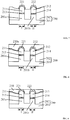
Figures 1~3 illustrate certain semiconductor structures corresponding to an existing fabrication process of a semiconductor structure; -
Figures 4~10 illustrate semiconductor structures corresponding to certain stages of a fabrication process of a semiconductor structure consistent with the disclosed embodiments; -
Figure 11 illustrates a semiconductor structure consistent with the disclosed embodiments; and -
Figure 12 illustrates an exemplary fabricating process of a semiconductor device consistent with the disclosed embodiments. - Reference will now be made in detail to the exemplary embodiments of the invention, which are illustrated in the accompanying drawings. Wherever possible, the same reference numbers will be used throughout the drawings to refer to the same or similar parts.
- As described above, semiconductor structures formed by current methods may have certain problems, including that the metal silicide of different semiconductor devices can easily be short-circuited.
Figures 1~3 show a semiconductor structure corresponding to an existing fabrication process. - As shown in
Figure 1 , abase 100 containing a first transistor region "a" and an adjacent second transistor region "b" is provided. Thebase 100 includes asubstrate 101 and anisolation structure 102. Thesubstrate 101 contains two fin portions, a first fin portion and a second fin portion. Theisolation structure 102 is formed on thesubstrate 101 and is around the first fin portion and the second fin portion. The top surfaces of the first fin portion and the second fin portion are exposed. - As shown in
Figure 1 , thesubstrate 101 is then etched, forming afirst trench 103 in the first transistor region "a" and asecond trench 104 in the second transistor region "b". - Before etching the
substrate 101, the fabrication method further includes forming a first gate structure and a second gate structure in the first transistor region "a" and the second transistor region "b" of thebase 100, respectively. Thesubstrate 101 under the first gate structure and the second gate structure forms the first channel and the second channel, respectively. - As shown in
Figure 2 , afirst stress layer 111 is formed in the first trench 103 (Figure 1 ) of the first transistor region "a", and asecond stress layer 112 is formed in the second trench 104 (Figure 1 ) of the second transistor region "b". - As shown in
Figure 3 , afirst covering layer 121 that covers thefirst stress layer 111 is formed in the first transistor region "a", and asecond covering layer 122 that covers thesecond stress layer 112 is formed in the second transistor region "b". The first coveringlayer 121 and the second coveringlayer 122 can be formed via epitaxial growth. The first coveringlayer 121 and the second coveringlayer 122 are used to form the metal silicide. - In the process of etching the
substrate 101 in the first transistor region "a" and the second transistor region "b" to form thefirst trench 103 and the second trench104, theisolation structure 101 around thefirst trench 103 and thesecond trench 104 is also etched, forming a depressed area in theisolation structure 102. As a result, the surface of the first channel is higher than the surface of theisolation structure 102 between the first fin portion and the second fin portion, and the surface of the second channel is higher than the surface of theisolation structure 102 between the first fin portion and the second fin portion. - However, in order for the subsequently formed
first stress layer 111 andsecond stress layer 112 to provide sufficient stress for the first channel and the second channel, the top surface of thefirst stress layer 111 should be higher than or at the same level with the surface of the first channel, and the surface of thesecond stress layer 112 should be higher than or at the same level with the surface of the second channel. Thefirst stress layer 111 and thesecond stress layer 112 may protrude from the surface of theisolation structure 102. - As shown in
Figure 3 , in the process of forming thefirst covering layer 121 and thesecond covering layer 122 that cover thefirst stress layer 111 and thesecond stress layer 112, for example, via epitaxial growth, the growth directions of thefirst covering layer 121 and thesecond covering layer 122 are not limited, and the growth rates of the crystal forming thefirst covering layer 121 and thesecond covering layer 122 are different along different directions. Thus, vertices can easily form along the faster growth directions of thefirst covering layer 121 and thesecond covering layer 122. Thefirst covering layer 121 and thesecond covering layer 122 can easily contact with each other at the vertices, causing the subsequently formed metal silicide short-circuited. - The present invention provides an improved fabrication process and semiconductor structures thereof. According to the disclosed semiconductor structures and methods, the short-circuit problem and other problems may be overcome by, for example, forming an isolation layer and additional covering layers.
- In the disclosed semiconductor structure, after forming the first stress layer and the second stress layer, the first covering layer that covers the first stress layer and the second covering layer that covers the second stress layer are formed. The first covering layer and the second covering layer are used to provide crystalline seeds for the subsequently formed third covering layer and forth covering layer, so that the crystallographic orientations of the third covering layer and the fourth covering layer are the same with the crystallographic orientations of the first covering layer and the second covering layer. After forming the first covering layer and the second covering layer, an isolation layer filling up the gap between the first covering layer and the second covering layer is formed. The surface of the isolation layer is higher than the vertices of the first covering layer and the second covering layer. The growth directions of the third covering layer and the fourth covering layer are limited during the epitaxial growth process of forming the third covering layer and the fourth covering layer. Thus, the third covering layer and the fourth covering layer do not form at the vertices of the first covering layer and the second covering layer, and the contact between the third covering layer and the fourth covering layer is avoided. The contact between the metal silicide in the first transistor region and the second transistor region is also avoided, and the electrical insulation among different semiconductor devices can be achieved.
- Correspondingly, the disclosed invention also provides a semiconductor structure. In the disclosed semiconductor structure, an isolation layer is between the first covering layer and the second covering layer. The surface of the isolation layer is higher than the vertices of the first covering layer and the second covering layer, and the vertices are not covered by the third covering layer or the fourth covering layer. Thus, the contact between the third covering layer and the fourth covering layer can be avoided. In addition, the first covering layer and the second covering layer are relatively thin and, therefore, it may be difficult for the first covering layer and the second covering layer to contact with each other.
-
Figure 12 illustrates an exemplary fabrication process of a semiconductor structure consistent with the disclosed embodiments; andFigures 4~10 illustrate semiconductor structures corresponding to certain stages of the exemplary fabrication process. - As shown in
Figure 12 , at the beginning of the fabrication process, a base is provided (S101).Figure 4 illustrates a corresponding semiconductor structure. - As shown in
Figure 4 , a base 200 containing a first transistor region I and a second transistor region II is provided. The first transistor region I and the second transistor region II are used to form a fin-field effect transistor (Fin-FET). The first transistor region I and the second transistor region II can also be used to form a planar transistor or other semiconductor device. - The base 200 may include a
substrate 201 and anisolation structure 202 on thesubstrate 201. Thesubstrate 201 may contain afirst fin portion 201 a in the first transistor region I and asecond fin portion 201b in the second transistor region II. The side walls of thefirst fin portion 201 a and thesecond fin portion 201 b are covered by theisolation structure 202, and the top surfaces of thefirst fin portion 201a and thesecond fin portion 201b are exposed. - Further, the
first fin portion 201a and thesecond fin portion 201b are used to form the drain and/or source region(s) of the Fin-FET. In one embodiment, thesubstrate 201 is made of silicon. In other embodiments, thesubstrate 201 can also be made of any other appropriate semiconductor material, such as germanium, silicon germanium or silicon on an insulator. - In one embodiment, the
isolation structure 202 is a shallow trench isolation structure, and theisolation structure 202 may be made of silicon oxide. In other embodiments, theisolation structure 202 can also be silicon nitride or silicon oxynitride. - Subsequently in the fabrication process, a first stress layer may be formed in the first transistor region I of the
base 200 and a second stress layer may be formed in the second transistor region II of thebase 200. The surface of the base 200 may be exposed by the first stress layer and the second stress layer. The first stress layer and the second stress layer may be used to provide corresponding stress for channels of the transistor. - Further, as described below, before forming the first stress layer in the first transistor region I of the
base 200 and the second stress layer in the second transistor region II of thebase 200, a first gate structure may be formed in the first transistor region I of thebase 200 and a second gate structure may be formed in the second transistor region II of thebase 200. Thesubstrate 201 under the first gate structure forms the first channel, and thesubstrate 201 under the second gate structure forms the second channel. The first stress layer is in thefirst fin portion 201 a on the sides of the first gate structure, and the second stress layer is in thesecond fin portion 201b on the sides of the second gate structure. - Returning to
Figure 12 , after providing the base containing the first transistor region and the second transistor region, a first trench may be formed in the first transistor region of the base and a second trench may be formed in the second transistor region of the base (S102).Figure 5 illustrates a corresponding semiconductor structure. - As shown in
Figure 5 , afirst trench 203 may be formed in the first transistor region I of thebase 200 and asecond trench 204 may be formed in the second transistor region II of thebase 200. - More specifically, a mask layer may be first formed on the surface of the
base 200. The surface of the base 200 in the first transistor region I, the surface of the base 200 in the second transistor region II, and the surface of theisolation structure 202 between the first transistor region I and the second transistor region II may be exposed by the mask layer. - In one embodiment, the surface of the
first fin portion 201a, the surface of thesecond fin portion 201b, and the surface of theisolation structure 202 between the surface of thefirst fin portion 201a and the surface of thesecond fin portion 201b are exposed by the mask layer. - The mask layer may be made of a material different from the material of the
substrate 201 and theisolation structure 202. In one embodiment, the mask layer is made of silicon nitride. - As shown in
Figure 5 , thebase 200 may then be etched using the mask layer as a mask. Thefirst trench 203 is then formed in the first transistor region I, and thesecond trench 204 is formed in the second transistor region II. Specifically, in one embodiment, thefirst fin portion 201a is etched to form thefirst trench 203 and thesecond fin portion 201b is etched to form thesecond trench 204. - Further, in the process of etching the
first fin portion 201a to form thefirst trench 203 and etching thesecond fin portion 201b to form thesecond trench 204, theisolation structure 202 around thefirst trench 203 and thesecond trench 204 may also be etched, forming a depressed area in theisolation structure 202, which may cause the surface of subsequently-formed first channel higher than the surface of theisolation structure 202 between thefirst fin portion 201a and thesecond fin portion 201b, and cause the surface of the second channel higher than the surface of theisolation structure 202 between thefirst fin portion 201 a and thesecond fin portion 201b. - In one embodiment, the
first trench 203 and thesecond trench 204 are formed by dry etching thefirst fin portion 201 a and thesecond fin portion 201b. In other embodiments, thefirst fin portion 201 a and thesecond fin portion 201 b can also be etched using a wet-etching method or using the combination of the dry and wet etching methods. - In one embodiment, the distance from the highest point of the
isolation structure 202 between thefirst fin portion 201 a and thesecond fin portion 201b to the bottom of thefirst trench 203 may form the depth 'h1' of thefirst trench 203. The distance from the highest point of theisolation structure 202 between thefirst fin portion 201 a and thesecond fin portion 201b to the bottom of thesecond trench 204 may form the depth 'h2' of thesecond trench 204. - In the process of etching the
first fin portion 201a and thesecond fin portion 201b to form thefirst trench 203 and thesecond trench 204, theisolation structure 202 around thefirst trench 203 and thesecond trench 204 is also etched. Thus, it is hard to increase the depth h1 of thefirst trench 203 and the depth h2 of thesecond trench 204. Specifically, in one embodiment, the depths h1 of thefirst trench 203 and the depth h2 of thesecond trench 204 are 50 ~ 100 Å. - Returning to
Figure 12 , after forming the first trench and the second trench, a first stress layer may be formed in the first trench of the base and a second stress layer may be formed in the second trench of the base (S103).Figure 6 illustrates a corresponding semiconductor structure. - As shown in
Figure 6 , afirst stress layer 211 is then formed in the first trench 203 (Figure 5 ), and asecond stress layer 212 is formed in the second trench 204 (Figure 5 ). - The surface of the first channel is higher than the surface of the
isolation structure 202 between thefirst fin portion 201a and thesecond fin portion 201b. In the process of forming thefirst stress layer 211 in thefirst trench 203, in order for thefirst stress layer 211 to provide sufficient stress for the first channel, the top surface of thefirst stress layer 211 may be higher than the surface of the first channel or at the same level with the surface of the first channel. Thus, the thickness of thefirst stress layer 211 is larger than the depth h1 of thefirst trench 203, causing thefirst stress layer 211 to protrude from the surface of theisolation structure 202. - Similarly, the surface of the second channel is higher than the surface of the
isolation structure 202 between thefirst fin portion 201 a and thesecond fin portion 201b. In the process of forming thesecond stress layer 212 in thesecond trench 204, in order for thesecond stress layer 212 to provide sufficient stress for the second channel, the top surface of thesecond stress layer 212 may be higher than the surface of the second channel or at the same level with the surface of the second channel. Thus, the thickness of thesecond stress layer 212 is larger than the depth h2 of thesecond trench 204, causing thesecond stress layer 212 to protrude from the surface of theisolation structure 202. - In one embodiment, the first transistor region I is used to form a PMOS transistor. Correspondingly, the
first stress layer 211 may be made of silicon germanium, and the germanium concentration may be in a range of 25% ~ 60%. In other embodiments, the first transistor region I can also be used to form an NMOS transistor, and the corresponding first stress layer may be made of silicon carbide. - In one embodiment, the second transistor region II is used to form a PMOS transistor. Correspondingly, the
second stress layer 212 is made of silicon germanium, and the germanium concentration is 25% ~ 60%. In other embodiments, the second transistor region can also be used to form an NMOS transistor, and the corresponding second stress layer may be made of silicon carbide. - In the process of forming the
first stress layer 211 in thefirst trench 203, if the thickness of thefirst stress layer 211 is too large, the integration degree of semiconductor devices can be affected; if the thickness of thefirst stress layer 211 is too small, it may be hard for thefirst stress layer 211 to provide sufficient stress for the first transistor channel. In one embodiment, the thickness of thefirst stress layer 211 may be in a range of approximately 100~300 Å. - Similarly, in the process of forming the
second stress layer 212 in thesecond trench 204, if the thickness of thesecond stress layer 212 is too large, the integration degree of semiconductor devices can be affected; if the thickness of thesecond stress layer 212 is too small, it is hard for thesecond stress layer 212 to provide sufficient stress for the second transistor channel. In one embodiment, the thickness of thesecond stress layer 212 may be in a range of approximately 100 ~ 300 Å. - In one embodiment, the
first stress layer 211 and thesecond stress layer 212 are fabricated by a selective epitaxial technique. The reactive gas for the selective epitaxial technique may include the silicon source gas, germanium source gas, chlorine gas, and hydrogen gas. The silicon source gas may be SiH4, SiH2C2, or Si2Cl6 with a flow rate in a range of approximately 1 slm ~ 1000 sccm. The germanium source gas is GeH4 with a flow rate in a range of approximately 500 sccm ~ 1000 sccm. The flow rates of the chlorine gas and the hydrogen gas may be in a range of approximately 0.1 slm ~ 50 slm. - In one embodiment, before forming the
first stress layer 211, the disclosed fabrication method may further include forming afirst seed layer 213 in thefirst trench 203 by epitaxial growth. Thefirst seed layer 213 may be used to smoothly change the lattice constant from thesubstrate 201 to thefirst stress layer 211, and to increase the lattice match between thefirst stress layer 211 and the crystal interface on which the first stress layer grows. Thus, the defects in thefirst stress layer 211 may be reduced and the crystalline quality of thefirst stress layer 211 may be improved. - In one embodiment, the
substrate 201 is made of silicon, and thefirst stress layer 211 is made of silicon germanium crystal. Thefirst seed layer 213 is made of silicon germanium crystal with a germanium concentration lower than the germanium concentration in thefirst stress layer 211. Specifically, the germanium concentration in thefirst seed layer 213 may be in a range of approximately 5% ~ 25%. - Similarly, in one embodiment, before forming the
second stress layer 212, the disclosed fabrication method further includes forming asecond seed layer 214 in thesecond trench 204 by epitaxial growth. Thesecond seed layer 214 is used to smoothly change the lattice constant from thesubstrate 201 to thesecond stress layer 212, and to increase the lattice match between thesecond stress layer 212 and the crystal interface on which the second stress layer grows. Thus, the defects in thesecond stress layer 212 may be reduced and the crystalline quality of thesecond stress layer 212 may be improved. - In one embodiment, the
substrate 201 is made of silicon, and thesecond stress layer 212 is made of silicon germanium crystal. Thesecond seed layer 214 is made of silicon germanium crystal with a germanium concentration lower than the germanium concentration in thesecond stress layer 212. Specifically, the germanium concentration in thesecond seed layer 214 may be in a range of approximately 5%~25%. - Further, a doping process may be performed on the
first stress layer 211 and thesecond stress layer 212 to form the source and/or drain region(s). Specifically, thefirst stress layer 211 and thesecond stress layer 212 are doped to form the source and drain regions by the on-site doping method during the process of the selective epitaxial growth. After forming thefirst stress layer 211 and thesecond stress layer 212, the ion implantation technique may also be employed to fabricate the source and drain regions. - Further, in one embodiment, before forming the
first seed layer 213 and thesecond seed layer 214, the disclosed fabrication method of a semiconductor structure may also include cleaning the bottom and side walls of thefirst trench 203 and thesecond trench 204 to remove the oxidation layer at the bottom and on the side walls of thefirst trench 203 and thesecond trench 204. Specifically, the bottom and side walls of thefirst trench 203 and thesecond trench 204 may be cleaned by a hydrofluoric acid solution. - Returning to
Figure 12 , after forming the first stress layer and the second stress layer, a first covering layer and a second covering layer may be formed (S104).Figure 7 illustrates a corresponding semiconductor structure. - As shown in
Figure 7 , thefirst covering layer 221 may be formed on the surface of thefirst stress layer 211 and thesecond covering layer 222 may be formed on the surface of thesecond stress layer 212 by, for example, an epitaxial growth process. There may be a gap between thefirst covering layer 221 and thesecond covering layer 222, and the gap may expose the surface of thebase 200. The adjacent side wall surfaces of thefirst covering layer 221 and thesecond covering layer 222 have vertices pointing to thesecond covering layer 221 and thefirst covering layer 221, respectively. - The gap may be the space surrounded by the side wall of the
first covering layer 221, the side wall of thesecond covering layer 222, the side wall of thefirst stress layer 211, and the side wall of thesecond stress layer 212, and the surface of the base 200 between the first transistor region I and the second transistor region II. - The
first covering layer 221 and thesecond covering layer 222 may be used to provide crystalline seeds for subsequently forming a third covering layer and a fourth covering layer, so that the crystallographic orientations of the third covering layer and the fourth covering layer may be the same with the crystallographic orientations of thefirst covering layer 221 and thesecond covering layer 222. - In one embodiment, the
first covering layer 221 and thesecond covering layer 222 may be made of silicon germanium crystal, in which the germanium concentration may be in a range of approximately 0% ~ 60%. In other words, thefirst covering layer 221 and thesecond covering layer 222 can also be made of pure silicon. - As the top surfaces of the
first stress layer 211 and thesecond stress layer 212 protrude from the surface of thebase 200, thefirst covering layer 221 and thesecond covering layer 222 can grow along both the <111> and the < 100> crystallographic directions. Because the growth of thefirst covering layer 221 and thesecond covering layer 222 along the <111> crystallographic direction is slower, thefirst covering layer 221 and thesecond covering layer 222 can form vertices at the intersections of the two (111) crystalline facets. If the thicknesses of thefirst covering layer 221 and thesecond covering layer 222 are too large, the vertices of thefirst covering layer 221 may be opt to contact with the vertices of thesecond covering layer 222; if the thicknesses of thefirst covering layer 221 and thesecond covering layer 222 are too small, it may be hard to provide high quality crystalline seeds for the subsequently formed third covering layer and fourth covering layer. In one embodiment, the thicknesses of thefirst covering layer 221 and thesecond covering layer 222 may be in a range of approximately 10 ~ 200 Å. - In one embodiment, the
first covering layer 211 and thesecond covering layer 212 are formed by the selective epitaxial technique. The reactive temperature of the selective epitaxial technique may be in a range of approximately 600 ~ 1000 °C and the reactive pressure may be in a range of approximately 1 ~ 500 torr. The reactive gases are silicon source gas, germanium source gas, chlorine gas, and hydrogen gas. The silicon source gas may be SiH4, SiH2C2 or Si2C6 with a flow rate of approximately 1 slm ~ 1000 sccm. The germanium source gas may be GeH4 with a flow rate of approximately 0 -1000 sccm. The flow rates of the chlorine and hydrogen gases may be in a range of approximately 0.1 slm ~ 50 slm. - Returning to
Figure 12 , after forming the first covering layer and the second covering layer, an isolation layer may be formed (S105).Figure 8 illustrates a corresponding semiconductor structure. - The isolation layer may be formed in the gap described above. The surface of the isolation layer may be higher than the vertices, and the top surfaces of the
first covering layer 221 and thesecond covering layer 222 may be exposed by the isolation layer. - In one embodiment, the isolation layer and the
isolation structure 202 may be made of the same material. In other words, the isolation layer may be made of silicon oxide, such as deep ultraviolet absorption oxide, borophosphosilicate glass or phosphosilicate glass. Using the same material for the isolation layer with theisolation structure 202 can make the isolation layer adhere to theisolation structure 202. In other embodiments, the isolation layer and theisolation structure 202 can also be made of different materials. For example, the isolation layer can also be made of silicon nitride. - The isolation layer may be used to separate the vertices of the
first covering layer 221 and thesecond covering layer 222, limiting the growth directions of the subsequently formed third covering layer and fourth covering layer, so that the third covering layer and the fourth covering layer do not form on the vertices. - More specifically, as shown in
Figure 8 , aninitial isolation layer 230a may be formed, covering thefirst covering layer 221 and thesecond covering layer 222 and filling up the gap. - In one embodiment, the
initial isolation layer 230a that covers thefirst covering layer 221 and thesecond covering layer 222 and that fills up the gap is formed by a fluid chemical vapor deposition process. The fluid chemical vapor deposition technique can form aninitial isolation layer 230a fully filling up the gap, and can effectively avoid the growth of the subsequently formed third covering layer and fourth covering layer on the vertices of thefirst covering layer 221 and thesecond covering layer 222. - Returning to
Figure 12 , after forming the isolation layer, the initial isolation layer on the first covering layer and the second covering layer may be removed (S106).Figure 9 illustrates a corresponding semiconductor structure. - As shown in
Figure 9 , theinitial isolation layer 230a on thefirst covering layer 221 and on the second covering layer 222 (Figure 8 ) is removed to expose thefirst covering layer 221 and thesecond covering layer 222, and the remainingisolation layer 230a may form theisolation layer 230. - In one embodiment, the
initial isolation layer 230a on thefirst covering layer 221 and thesecond covering layer 222 may be removed by wet etching, forming theisolation layer 230. In other embodiments, the isolation layer on the first covering layer and the second covering layer can also be removed by dry etching. - In one embodiment, after removing the
initial isolation layer 230a on thefirst covering layer 221 and on thesecond covering layer 222, the surface of the retainedisolation layer 230a in the gap is at the same level with the top surfaces of thefirst covering layer 221 and thesecond covering layer 222. That is, theisolation layer 230 covers all the (111) crystalline facets of thefirst covering layer 221 and thesecond covering layer 222 and exposes only the (100) crystalline facets. Therefore, theisolation layer 230 can substantially limit the growth directions of the third covering layer and the fourth covering layer. In other embodiments, the isolation layer can also be formed by the fluid chemical vapor deposition technique, with the surface of the isolation layer higher than the position of the vertices, but lower than the top surfaces of the first covering layer and the second covering layer. - Returning to
Figure 12 , after removing the isolation layer on the first covering layer and the second covering layer, a third covering layer and a fourth covering layer may be formed (S107).Figure 10 illustrates a corresponding semiconductor structure. - As shown in
Figure 10 , athird covering layer 231 is formed on thefirst covering layer 221 and afourth covering layer 232 is formed on thesecond covering layer 222 by, for example, an epitaxial growth process. - The
third covering layer 231 and thefourth covering layer 232 may be used to provide crystalline seeds for subsequently forming the metal silicide, so that the crystallographic orientations of thethird covering layer 231 and thefourth covering layer 232 may be the same with the crystallographic orientations of thefirst covering layer 221 and thesecond covering layer 222. - In one embodiment, the
third covering layer 231 and thefourth covering layer 232 may be made of the same material with thefirst covering layer 221 and thesecond covering layer 222. Using the same material for thefirst covering layer 221, thesecond covering layer 222, thethird covering layer 231, and thefourth covering layer 232 can increase the lattice match between thefirst covering layer 221 and thethird covering layer 231 and increase the lattice match between thesecond covering layer 222 and thefourth covering layer 232. Thus, the defects in thethird covering layer 231 and in thefourth covering layer 232 may be reduced and the crystalline quality of thethird covering layer 231 and thefourth covering layer 232 is improved. - In one embodiment, the
third covering layer 231 and thefourth covering layer 232 are formed by the selective epitaxial growth technique, and the technical parameters of the selective epitaxial growth technique may be the same as the technical parameters for forming thefirst covering layer 221 and thesecond covering layer 222. - In one embodiment, because the
isolation layer 230 covers all the (111) crystalline facets of thefirst covering layer 221 and thesecond covering layer 222 and exposes only the (100) crystalline facets, in the process of forming thethird covering layer 231 and thefourth covering layer 232 by epitaxial growth, thethird covering layer 231 and thefourth covering layer 232 can only grow along the <100> crystallographic direction. In other words, thethird covering layer 231 and thefourth cover layer 232 can only grow upwards. In other embodiments, theisolation layer 230 can also cover only a part of the (111) crystalline facets of thefirst covering layer 221 and thesecond covering layer 222, and thus thethird covering layer 231 and thefourth covering layer 232 can also form on the (111) crystalline facets of thefirst covering layer 201 and thesecond covering layer 222 that are exposed by theisolation layer 230. - Therefore, in one embodiment, the thicknesses of the
third covering layer 231 and thefourth covering layer 232 are not restricted by the width of theisolation layer 202 between thefirst stress layer 211 and thesecond stress layer 212. In other words, the total thickness of thefirst covering layer 221 and thethird covering layer 231 and the total thickness of thesecond covering layer 222 and thefourth covering layer 232 can be relatively large. However, if the thicknesses of thethird covering layer 231 and thefourth covering layer 232 are too large, the integration degree of semiconductor devices will be affected. In one embodiment, the thicknesses of thethird covering layer 231 and thefourth covering layer 232 may be in a range of approximately 30 ~ 100 Å. - In one embodiment, the distance between the
third covering layer 231 and thefourth covering layer 232 may be determined by the distance between thefirst covering layer 221 and thesecond covering layer 222 that are exposed by theisolation layer 230. In one embodiment, thethird covering layer 231 may only be formed on the exposed (100) facets of thefirst covering layer 221, and thefourth layer 232 may only be formed on the exposed (100) facets of thesecond covering layer 222. Therefore, the distance between thethird covering layer 231 and thefourth covering layer 232 may be the distance between the (100) facets of thefirst covering layer 221 and thesecond covering layer 222. - In the disclosed embodiment, if the thickness of the
isolation structure 202 between thefirst stress layer 211 and thesecond stress layer 212 is too large, it is not good for increasing the integration degree of the formed semiconductor devices; if the thickness of theisolation structure 202 between thefirst stress layer 211 and thesecond stress layer 212 is too small, it tends to cause a contact between thefirst covering layer 221 and thesecond covering layer 222 or cause a contact between thethird covering layer 231 and thefourth covering layer 232. In one embodiment, because the thicknesses of thefirst covering layer 231 and thesecond covering layer 232 are relatively small, the thickness of theisolation structure 202 between thefirst stress layer 211 and thesecond stress layer 212 can be as small as there is no contact between thefirst covering layer 221 and thesecond covering layer 222 or between thethird covering layer 231 and thefourth covering layer 232. In one embodiment, the thickness of theisolation structure 202 between thefirst stress layer 211 and thesecond stress layer 212 may be in a range of approximately 28 nm ~ 1 µm. - Further, after forming the
third covering layer 231 on thefirst covering layer 221 and forming thefourth covering layer 232 on thesecond covering layer 222 by epitaxial growth, the disclosed fabrication method of a semiconductor structure also includes metallizing thefirst covering layer 221, thesecond covering layer 222, thethird covering layer 231, and thefourth covering layer 232 to form a metal silicide. The formed metal silicide can electrically connect the transistor with external circuits. - Specifically, the procedures to form the metal silicide include forming a metallic layer on the
first covering layer 221, thesecond covering layer 221, thethird covering layer 231, and the fourth covering layer, so that the metal atoms can be diffused into thefirst covering layer 221, thesecond covering layer 222, thethird covering layer 231, and thefourth covering layer 232 to form the metal silicide. - Thus, by using the disclosed fabrication process to form a semiconductor structure, after forming the first stress layer and the second stress layer, the first covering layer that covers the first stress layer and the second covering layer that covers the second stress layer are then formed. The first covering layer and the second covering layer are used to provide crystalline seeds for subsequently forming the third covering layer and the fourth covering layer, respectively, so that the third covering layer and the fourth covering layer have the same crystallographic orientations with the first covering layer and the second covering layer. After forming the first covering layer and the second covering layer, an isolation layer that fills up the gap between the first covering layer and the second covering layer is formed. The surface of the isolation layer is higher than the vertices of the first covering layer and the second covering layer. Thus, the growth of the third covering layer and the fourth covering layer along the vertex direction is limited. During the process of forming the third covering layer and the fourth covering layer by epitaxial growth, the third covering layer and the fourth covering layer do not grow along the vertex direction. Therefore, the contact between the third covering layer and the fourth covering layer is avoided, and further the contact between the metal silicide formed in the first transistor region and the second transistor region is avoided, achieving electrical insulating between different semiconductor devices.
-
Figure 11 illustrates a semiconductor structure corresponding to the disclosed fabrication process. As shown inFigure 11 , a base 300 containing a first transistor region "A" and an adjacent second transistor region "B" is provided. - In one embodiment, the first transistor region "A" and the second transistor region "B" are used to form a Fin-FET. In other embodiments, the first transistor region "A" and the second transistor region "B" can also be used to form a planar transistor.
- Accordingly, in one embodiment, the
base 300 includes asubstrate 301 and an isolation structure 302 on thesubstrate 301. Thesubstrate 301 includes afirst fin portion 301a in the first transistor region "A" and asecond fin portion 301b in the second transistor region "B". Thefirst fin portion 301a and thesecond fin portion 301b are used to form the drain and source regions of the Fin-FET. - In one embodiment, the
substrate 301 is made of silicon. In other embodiments, thesubstrate 301 can also be made of any other appropriate semiconductor, such as germanium, silicon germanium or silicon on an insulator. - In one embodiment, the isolation structure 302 is a shallow trench isolation structure. The isolation structure 302 is made of silicon oxide. However, in the disclosed semiconductor structure there is no restriction on the material of the isolation structure 302. The isolation structure 302 can also be made of silicon nitride or silicon oxynitride.
- As shown in
Figure 11 , thefirst stress layer 311 is in the first transistor region "A" of thebase 300, and thesecond stress layer 312 is in the second transistor region "B" of thebase 300. Thefirst stress layer 311 and thesecond stress layer 312 are exposed by thebase 300. - The
first stress layer 311 and thesecond stress layer 312 are used to provide stress for channels of the transistor. - In one embodiment, a PMOS transistor is formed in the first transistor region "A". The corresponding
first stress layer 311 made of is silicon germanium, and the germanium concentration in thefirst stress layer 311 may be in a range of approximately 25% ~ 50%. In other embodiments, the first transistor region can also be used to form an NMOS transistor, and the corresponding first stress layer is made of silicon carbide. - In one embodiment, a PMOS transistor is formed in the second transistor region "B". The corresponding
second stress layer 312 is made of silicon germanium, and the germanium concentration in thesecond stress layer 312 may be in a range of approximately 25% ~ 50%. In other embodiments, the second transistor region can also be used to form an NMOS transistor, and the corresponding second stress layer is made of silicon carbide. - In one embodiment, there are a first trench in the first transistor region "A" and a second trench in the second transistor region "B". The first trench and the second trench are used to hold the
first stress layer 311 and thesecond stress layer 312. - The depth of the first trench and the second trench is smaller than the thickness of the
first stress layer 311 and thesecond stress layer 312. Specifically, in one embodiment, the depth of the first trench and the second trench may be in a range of approximately 50 ~ 100 Å. - Further, if the thickness of the
first stress layer 311 is too large, the integration degree of semiconductor devices will be affected; if the thickness of thefirst stress layer 311 is too small, it is hard to provide sufficient stress for the transistor channels. Therefore, the thickness of thefirst stress layer 311 should not be too small. Specifically, in one embodiment, the thickness of thefirst stress layer 311 may be in a range of approximately 100 ~ 300 Å. In other words, the depth of the first trench is smaller than the thickness of thefirst stress layer 311. Thus, the top surface of thefirst stress layer 311 protrudes from the first trench. - Similarly, if the thickness of the
second stress layer 312 is too large, the integration degree of semiconductor devices will be affected; if the thickness of thesecond stress layer 312 is too small, it is hard to provide sufficient stress for the channels of the transistor. Therefore, the thickness of thesecond stress layer 312 should not be too small. Specifically, in one embodiment, the thickness of thesecond stress layer 312 may be in a range of approximately 100 ~ 300 Å. In other words, the depth of the second trench is smaller than the thickness of thesecond stress layer 312. Therefore, the top surface of thesecond stress layer 312 protrudes from the second trench. - In one embodiment, the semiconductor structure also includes a
first seed layer 313 under thefirst stress layer 311. Thefirst seed layer 313 is used to smoothly change the lattice constant from thesubstrate 301 to thefirst stress layer 311, and increase the lattice match between thefirst stress layer 311 and the crystal interface on which the first stress layer grows. Thus, the crystalline quality of thefirst stress layer 311 is improved. - In one embodiment, the
substrate 301 is made of silicon. Thefirst stress layer 311 is made of the silicon germanium crystal. Thefirst seed layer 313 is made of the silicon germanium crystal, and the germanium concentration in thefirst seed layer 312 is smaller than the germanium concentration in thefirst stress layer 311. Specifically, the germanium concentration in thefirst seed layer 313 may be in a range of approximately 5% ~ 25%. - Similarly, in one embodiment, the semiconductor structure also includes a
second seed layer 314 under thesecond stress layer 312. Thesecond seed layer 313 is used to smoothly change the lattice constant from thesubstrate 301 to thesecond stress layer 312, and increase the lattice match between thesecond stress layer 312 and the crystal interface on which the second stress layer grows. Thus, the crystalline quality of thesecond stress layer 312 is improved. - In one embodiment, the
substrate 301 is made of silicon. Thesecond stress layer 312 is made of the silicon germanium crystal. Thesecond seed layer 314 is made of the silicon germanium crystal, and the germanium concentration in thesecond seed layer 314 is smaller than the germanium concentration in thesecond stress layer 312. Specifically, the germanium concentration in thesecond seed layer 314 may be in a range of approximately 5% ~ 25%. - As shown in
Figure 11 , thefirst covering layer 321 is on the surface of thefirst stress layer 311, and thesecond covering layer 322 is on the surface of the second stress layer. The neighboring side walls of thefirst covering layer 321 and thesecond covering layer 322 have vertices pointing to each other. - The
first covering layer 321 and thesecond covering layer 322 are used to provide crystalline seeds for subsequently forming the third covering layer and the fourth covering layer, so that the crystallographic orientations of the third covering layer and the fourth covering layer are the same with the crystallographic orientations of the first covering layer and the second covering layer, respectively. - In one embodiment, the
first covering layer 321 and thesecond covering layer 322 are made of silicon germanium crystal, and the silicon concentration may be in a range of approximately 0 ~ 60%. In other words, thefirst covering layer 321 and thesecond covering layer 322 can also be made of pure silicon. - If the thicknesses of the
first covering layer 321 and thesecond covering layer 322 are too large, it tends to make the vertices of thefirst covering layer 321 and thesecond covering layer 322 contact with each other; if the thicknesses of thefirst covering layer 321 and thesecond covering layer 322 are too small, it is hard to provide high quality crystalline seeds for the growth of the third covering layer and the fourth covering layer to make the crystallographic orientations of the third covering layer and the fourth covering layer the same with the crystallographic orientations of thefirst covering layer 321 and thesecond covering layer 322. Therefore, in one embodiment, the thicknesses of thefirst covering layer 321 and thesecond covering layer 322 may be in a range of approximately 10 ~ 200 Å. - As shown in
Figure 11 , theisolation layer 330 is between thefirst covering layer 321 and thesecond covering layer 322, and the surface of theisolation layer 330 is higher than the position of the vertices. Further, the top surfaces of thefirst covering layer 321 and thesecond covering layer 322 are exposed by theisolation layer 330. - The
isolation layer 330 is used to isolate thefirst covering layer 321 and thesecond covering layer 322 and limit the growth directions of the subsequently formed third covering layer and fourth covering layer, so that growth of the third covering layer and the fourth covering layer on the vertices of thefirst covering layer 321 and thesecond covering layer 322 is avoided. - In one embodiment, the
isolation layer 330 and the isolation structure 302 are made of the same material. In other words, theisolation layer 330 is made of silicon oxide, such as, deep ultraviolet absorption oxides, borophosphosilicate glass or phosphosilicate glass. Using the same material for theisolation layer 330 with the isolation structure 302 can make theisolation layer 330 well adhere to the isolation structure 302. In other embodiments, the isolation layer and the isolation structure can also be made of different materials. For example, the isolation layer can also be made of silicon nitride. - In one embodiment, the surface of the
isolation layer 330 is at the same level with the top surfaces of thefirst covering layer 321 and thesecond covering layer 322. In other words, theisolation layer 330 covers the (111) crystal facets of thefirst covering layer 321 and thesecond covering layer 322 and expose only the (100) crystal facets. In other embodiments, the surface of theisolation layer 330 can also be higher than the position of the vertices, but lower than the top surfaces of thefirst covering layer 321 and thesecond covering layer 322. - As shown in
Figure 11 , thethird covering layer 331 is on the surface of thefirst covering layer 321, and thefourth covering layer 332 is on the surface of thesecond covering layer 322. - The
third covering layer 331 and thefourth covering layer 332 are used to provide crystalline seeds for subsequently forming the metal silicide, so that the crystallographic orientations of thethird covering layer 331 and thefourth covering layer 332 are the same with the crystallographic orientations of thefirst covering layer 321 and thesecond covering layer 322. - In one embodiment, the
third covering layer 331 and thefourth covering layer 332 are made of the same material with thefirst covering layer 321 and thesecond covering layer 322. Using the same material for thefirst covering layer 321, thesecond covering layer 322, thethird covering layer 331, and thefourth covering layer 332 can increase the lattice match between thefirst covering layer 321 and thethird covering layer 331, and increase the lattice match between thesecond covering layer 322 and thefourth layer 332. Thus, the defects in thethird covering layer 331 and thefourth covering layer 332 are reduced and the crystalline quality of thethird covering layer 331 and thefourth covering layer 332 is improved. - In one embodiment, the
isolation layer 330 covers the (111) crystal facets of thefirst covering layer 321 and thesecond covering layer 322 and exposes only the (100) crystal facets. Thus, thethird covering layer 331 is only on the (100) crystal facets of thefirst covering layer 321 and thefourth covering layer 332 is only on the (100) crystal facets of thesecond covering layer 322. In other embodiments, the isolation layer can also cover only a part of the (111) facets of the first covering layer and the second covering layer. Therefore, the third covering layer can also form on the (111) facets of the first covering layer that are exposed by the isolation layer, and the fourth covering layer can also form on the (111) facets of the second covering layer that exposed by the isolation layer. - In one embodiment, the thickness of the
third covering layer 331 and thefourth covering layer 332 is unrestricted by the width of the isolation structure 302 between thefirst stress layer 311 and thesecond stress layer 312. In other words, the total thickness of thefirst covering layer 321 and thethird covering layer 331 and the total thickness of thesecond covering layer 322 and thefourth covering layer 332 can be relatively large. However, if the thickness of thethird covering layer 331 and thefourth covering layer 332 is too large, the integration degree of semiconductor devices can be affected. Specifically, the thickness of thethird covering layer 331 and thefourth covering layer 332 may be in a range of approximately 30 ~ 100 Å. - If the thickness of the isolation structure 302 between the
first stress layer 311 and thesecond stress layer 312 is too large, it is not good for increasing the integration degree of the formed semiconductor devices; if the thickness of the isolation structure 302 between thefirst stress layer 311 and thesecond stress layer 312 is too small, it can easily cause a contact between thefirst covering layer 311 and thesecond covering layer 312 or a contact between thethird covering layer 331 and thefourth covering layer 332. In one embodiment, the thicknesses of thefirst covering layer 321 and thesecond covering layer 322 are relatively small. Thus, the thickness of the isolation structure 302 between thefirst stress layer 311 and thesecond stress layer 312 can be as small as there is no contact between thefirst covering layer 321 and thesecond covering layer 322. Specifically, the thickness of the isolation structure 302 between thefirst stress layer 311 and thesecond stress layer 312 may be in a range of approximately 28 nm ~ 1 µm. - In summary, in the semiconductor structure of the disclosed invention, an isolation layer is between the first covering layer and the second covering layer, and the surface of the isolation layer is higher than the vertices of the first covering layer and the second covering layer. Thus, there is no the third covering layer or the fourth covering layer on the vertices, avoiding the contact between the third covering layer and the fourth covering layer. In addition, the first covering layer and the second covering layer are relatively thin, and the first covering layer and the second covering layer are unable to contact.
Claims (13)
- A method of forming a semiconductor structure, comprising of:providing a base having a first transistor region and a second transistor region adjacent to the first transistor region;forming a first stress layer in the first transistor region and a second stress layer in the second transistor region, with the first stress layer and the second stress layer exposing part of a surface of the base;forming a first covering layer on a surface of the first stress layer and a second covering layer on a surface of the second stress layer by epitaxial growth, with a gap between the first covering layer and the second covering layer exposing the surface of the base, and the neighboring side walls of the first covering layer and the second covering layer have vertices pointing to each other;forming an isolation layer filling up the gap, and a surface of the isolation layer is higher than the vertices, exposing top surfaces of the first covering layer and the second covering layer; andforming a third covering layer on the first covering layer and a fourth covering layer on the second covering layer by epitaxial growth.
- The method according to claim 1, wherein forming an isolation layer filling up the gap further includes:forming an initial isolation layer covering the first covering layer and the second covering layer and filling up the gap, wherein preferably the initial isolation layer is formed by using a fluid chemical vapor deposition process; andremoving the initial isolation layer that is on the top surfaces of the first covering layer and the second covering layer while retaining the initial isolation layer filling up the gap to form the isolation layer, wherein preferably the initial isolation layer is removed by wet etching or dry etching.
- The method according to claim 1 or 2, wherein:the base includes a substrate and an isolation structure between the first transistor region and the second transistor region; andwherein forming a first stress layer in the first transistor region and a second stress layer in the second transistor region preferably further includes: forming a mask layer on the surface of the base, exposing the base within the first transistor region and the second transistor region, and the isolation structure surface between the first transistor region and the second transistor region, etching the base using the mask layer as a mask to form a first trench in the first transistor region and a second trench in the second transistor region, and forming the first stress layer in the first trench and the second stress layer in the second trench.
- The method according to any one of the claims 1-3, wherein:the surface of the isolation layer is at a same level as the top surfaces of the first covering layer and the second covering layer when forming the initial isolation layer.
- The method according to any one of the claims 1-4, wherein the semiconductor structure comprises at least one of the following dimensions:a thickness of the third covering layer and the fourth covering layer is in a range of approximately 30 ~ 100 Å;a thickness of the isolation layer is in a range of approximately 10 ~ 500 Å;a thickness of the first covering layer and the second covering layer is in a range of approximately 10 ~ 200 Å; anda width of the base between the first stress layer and the second stress layer in a range of approximately 28 nm ~1 µm.
- The method according to any one of the claims 1-5, wherein:the isolation layer is made of deep ultraviolet absorbing oxide, borophosphosilicate glass, or phosphosilicate glass.
- The method according to any one of the claims 1-6, wherein:the first covering layer, the second covering layer, the third covering layer, and the fourth covering layer are made of a same material.
- The method according to any one of the claims 1-7, wherein:the first covering layer, the second covering layer, the third covering layer, and the fourth covering layer are made of silicon germanium.
- A semiconductor structure, includes:a base having a first transistor region and a second transistor region;a first stress layer in the first transistor region and a second stress layer in the second transistor region of the base, wherein the base is exposed by the first stress layer and the second stress layer;a first covering layer and a second covering layer formed on surfaces of the first stress layer and the second stress layer, respectively, and side walls of the first covering layer and the second covering layer have vertices pointing to each other;an isolation layer between the first covering layer and the second covering layer, and a top surface of the isolation layer is higher than the vertices, exposing the surfaces of the first covering layer and the second covering layer; anda third covering layer and a fourth covering layer formed on the surfaces of the first covering layer and the second covering layer, respectively.
- The semiconductor structure according to claim 9, wherein:the surface of the isolation layer is at a same level with the surfaces of the first covering layer and the second covering layer.
- The semiconductor structure according to claim 9 or 10, wherein the structure comprises at least one of the following dimensions:a thickness of the third covering layer and the fourth covering layer is in a range of approximately 30 ~ 100 Å; a width of the base between the first stress layer and the second stress layer is in a range of approximately 28 nm ~ 1 µm;a thickness of the first covering layer and the second covering layer is in a range of approximately 10 ~ 200 Å; anda thickness of the isolation layer between the first covering layer and the second covering layer is in a range of approximately 10 ~ 500 Å.
- The semiconductor structure according to any one of the claims 9-11, wherein:the isolation layer is made of deep ultraviolet absorbing oxide, borophosphosilicate glass, or phosphosilicate glass.
- The semiconductor structure according to any one of the claims 9-12, wherein:the first covering layer, the second covering layer, the third covering layer, and the fourth covering layer are made of a same material.
Applications Claiming Priority (1)
| Application Number | Priority Date | Filing Date | Title |
|---|---|---|---|
| CN201610006664.8A CN106952909B (en) | 2016-01-06 | 2016-01-06 | Semiconductor structure and method of forming the same |
Publications (1)
| Publication Number | Publication Date |
|---|---|
| EP3190625A1 true EP3190625A1 (en) | 2017-07-12 |
Family
ID=57777452
Family Applications (1)
| Application Number | Title | Priority Date | Filing Date |
|---|---|---|---|
| EP16207265.6A Withdrawn EP3190625A1 (en) | 2016-01-06 | 2016-12-29 | Semiconductor structure and fabrication method thereof |
Country Status (3)
| Country | Link |
|---|---|
| US (1) | US10147816B2 (en) |
| EP (1) | EP3190625A1 (en) |
| CN (1) | CN106952909B (en) |
Families Citing this family (5)
| Publication number | Priority date | Publication date | Assignee | Title |
|---|---|---|---|---|
| CN110364483B (en) * | 2018-03-26 | 2021-08-06 | 中芯国际集成电路制造(上海)有限公司 | Semiconductor structure and method of forming the same |
| CN108682685B (en) * | 2018-05-31 | 2023-12-12 | 长江存储科技有限责任公司 | Semiconductor device and manufacturing method |
| US10861969B2 (en) * | 2018-07-16 | 2020-12-08 | Taiwan Semiconductor Manufacturing Co., Ltd. | Method of forming FinFET structure with reduced Fin buckling |
| KR102866524B1 (en) * | 2020-09-01 | 2025-10-01 | 삼성전자주식회사 | Semiconductor device |
| US20220359199A1 (en) * | 2021-05-07 | 2022-11-10 | Taiwan Semiconductor Manufacturing Company, Ltd. | Fin structure with reduced defects and manufacturing method thereof |
Citations (3)
| Publication number | Priority date | Publication date | Assignee | Title |
|---|---|---|---|---|
| US20150137181A1 (en) * | 2013-11-19 | 2015-05-21 | International Business Machines Corporation | Stress inducing contact metal in finfet cmos |
| US20150214366A1 (en) * | 2014-01-24 | 2015-07-30 | Taiwan Semiconductor Manufacturing Company Ltd. | Embedded source or drain region of transistor with downward tapered region under facet region |
| US20150249153A1 (en) * | 2014-02-28 | 2015-09-03 | Stmicroelectronics, Inc. | Method to form localized relaxed substrate by using condensation |
Family Cites Families (12)
| Publication number | Priority date | Publication date | Assignee | Title |
|---|---|---|---|---|
| US9159834B2 (en) * | 2013-03-14 | 2015-10-13 | International Business Machines Corporation | Faceted semiconductor nanowire |
| KR102068980B1 (en) * | 2013-08-01 | 2020-01-22 | 삼성전자 주식회사 | Semiconductor device and method for fabricating the same |
| US9076823B2 (en) * | 2013-09-11 | 2015-07-07 | Taiwan Semiconductor Manufacturing Company, Ltd. | Bi-layer metal deposition in silicide formation |
| US8878300B1 (en) * | 2013-09-18 | 2014-11-04 | Stmicroelectronics, Inc. | Semiconductor device including outwardly extending source and drain silicide contact regions and related methods |
| US9263520B2 (en) * | 2013-10-10 | 2016-02-16 | Globalfoundries Inc. | Facilitating fabricating gate-all-around nanowire field-effect transistors |
| US9293462B2 (en) * | 2014-01-29 | 2016-03-22 | GlobalFoundries, Inc. | Integrated circuits with dual silicide contacts and methods for fabricating same |
| US9275906B2 (en) * | 2014-05-01 | 2016-03-01 | Globalfoundries Inc. | Method for increasing a surface area of epitaxial structures in a mixed N/P type fin semiconductor structure by forming multiple epitaxial heads |
| US9385197B2 (en) * | 2014-08-29 | 2016-07-05 | Taiwan Semiconductor Manufacturing Co., Ltd | Semiconductor structure with contact over source/drain structure and method for forming the same |
| US9431303B2 (en) * | 2014-10-17 | 2016-08-30 | Globalfoundries Inc. | Contact liners for integrated circuits and fabrication methods thereof |
| CN105845725B (en) * | 2015-01-12 | 2019-01-22 | 中芯国际集成电路制造(上海)有限公司 | A semiconductor device and its manufacturing method and electronic device |
| CN106920776B (en) * | 2015-12-25 | 2019-12-03 | 中芯国际集成电路制造(上海)有限公司 | Method of forming a fin transistor |
| US10796924B2 (en) * | 2016-02-18 | 2020-10-06 | Taiwan Semiconductor Manufacturing Co., Ltd. | Semiconductor device and manufacturing method thereof by forming thin uniform silicide on epitaxial source/drain structure |
-
2016
- 2016-01-06 CN CN201610006664.8A patent/CN106952909B/en active Active
- 2016-12-29 EP EP16207265.6A patent/EP3190625A1/en not_active Withdrawn
-
2017
- 2017-01-04 US US15/397,949 patent/US10147816B2/en active Active
Patent Citations (3)
| Publication number | Priority date | Publication date | Assignee | Title |
|---|---|---|---|---|
| US20150137181A1 (en) * | 2013-11-19 | 2015-05-21 | International Business Machines Corporation | Stress inducing contact metal in finfet cmos |
| US20150214366A1 (en) * | 2014-01-24 | 2015-07-30 | Taiwan Semiconductor Manufacturing Company Ltd. | Embedded source or drain region of transistor with downward tapered region under facet region |
| US20150249153A1 (en) * | 2014-02-28 | 2015-09-03 | Stmicroelectronics, Inc. | Method to form localized relaxed substrate by using condensation |
Also Published As
| Publication number | Publication date |
|---|---|
| CN106952909A (en) | 2017-07-14 |
| US10147816B2 (en) | 2018-12-04 |
| US20170194496A1 (en) | 2017-07-06 |
| CN106952909B (en) | 2020-03-10 |
Similar Documents
| Publication | Publication Date | Title |
|---|---|---|
| CN109841680B (en) | Semiconductor device with a semiconductor device having a plurality of semiconductor chips | |
| US11367660B2 (en) | Semiconductor method and device | |
| US9653574B2 (en) | Selective etching in the formation of epitaxy regions in MOS devices | |
| US7154118B2 (en) | Bulk non-planar transistor having strained enhanced mobility and methods of fabrication | |
| US10037924B2 (en) | Fin-FET device and fabrication method thereof | |
| KR100867781B1 (en) | Metal gate transistors with epitaxial source and drain regions | |
| US9425287B2 (en) | Reducing variation by using combination epitaxy growth | |
| US10090393B2 (en) | Method for forming a field effect transistor device having an electrical contact | |
| US9741824B2 (en) | Semiconductor device and fabrication method thereof | |
| US20080194070A1 (en) | Metal-oxide-semiconductor transistor device, manufacturing method thereof, and method of improving drain current thereof | |
| US10147816B2 (en) | Semiconductor structure and fabrication method thereof | |
| US20200043927A1 (en) | Semiconductor Device and Method | |
| US20190157425A1 (en) | Semiconductor device and fabrication method thereof | |
| US11217446B2 (en) | Method for fabricating an integrated circuit including a NMOS transistor and a PMOS transistor | |
| KR20160061615A (en) | Methods of manufacturing semiconductor devices | |
| CN104425379A (en) | Forming method of semiconductor device | |
| JP2008171999A (en) | Semiconductor device and manufacturing method thereof | |
| JP2007088138A (en) | Manufacturing method of semiconductor device | |
| KR100725455B1 (en) | Method of manufacturing a semiconductor memory device having an elevated source / drain | |
| KR20050087541A (en) | Fin type field effect transistor and method of manufacturing the same | |
| TWI485783B (en) | Semiconductor device having packaged pressure source region and manufacturing method thereof | |
| TWI921879B (en) | Semiconductor device and method for fabricating the same | |
| WO2007035660A1 (en) | Method to form a device on a soi substrate | |
| TW202610456A (en) | Semiconductor device and method for fabricating the same | |
| CN122002888A (en) | Semiconductor device and method for manufacturing the same |
Legal Events
| Date | Code | Title | Description |
|---|---|---|---|
| PUAI | Public reference made under article 153(3) epc to a published international application that has entered the european phase |
Free format text: ORIGINAL CODE: 0009012 |
|
| STAA | Information on the status of an ep patent application or granted ep patent |
Free format text: STATUS: THE APPLICATION HAS BEEN PUBLISHED |
|
| AK | Designated contracting states |
Kind code of ref document: A1 Designated state(s): AL AT BE BG CH CY CZ DE DK EE ES FI FR GB GR HR HU IE IS IT LI LT LU LV MC MK MT NL NO PL PT RO RS SE SI SK SM TR |
|
| AX | Request for extension of the european patent |
Extension state: BA ME |
|
| RAP1 | Party data changed (applicant data changed or rights of an application transferred) |
Owner name: SEMICONDUCTOR MANUFACTURING INTERNATIONAL CORPORAT |
|
| STAA | Information on the status of an ep patent application or granted ep patent |
Free format text: STATUS: REQUEST FOR EXAMINATION WAS MADE |
|
| 17P | Request for examination filed |
Effective date: 20171228 |
|
| RBV | Designated contracting states (corrected) |
Designated state(s): AL AT BE BG CH CY CZ DE DK EE ES FI FR GB GR HR HU IE IS IT LI LT LU LV MC MK MT NL NO PL PT RO RS SE SI SK SM TR |
|
| RAP1 | Party data changed (applicant data changed or rights of an application transferred) |
Owner name: SEMICONDUCTOR MANUFACTURING INTERNATIONAL (BEIJING Owner name: SEMICONDUCTOR MANUFACTURING INTERNATIONAL (SHANGHA |
|
| STAA | Information on the status of an ep patent application or granted ep patent |
Free format text: STATUS: EXAMINATION IS IN PROGRESS |
|
| 17Q | First examination report despatched |
Effective date: 20200219 |
|
| STAA | Information on the status of an ep patent application or granted ep patent |
Free format text: STATUS: THE APPLICATION IS DEEMED TO BE WITHDRAWN |
|
| 18D | Application deemed to be withdrawn |
Effective date: 20200630 |