EP3190466A1 - Roller and image forming apparatus using same - Google Patents
Roller and image forming apparatus using same Download PDFInfo
- Publication number
- EP3190466A1 EP3190466A1 EP15838890.0A EP15838890A EP3190466A1 EP 3190466 A1 EP3190466 A1 EP 3190466A1 EP 15838890 A EP15838890 A EP 15838890A EP 3190466 A1 EP3190466 A1 EP 3190466A1
- Authority
- EP
- European Patent Office
- Prior art keywords
- roller
- layer
- filler layer
- base layer
- image forming
- Prior art date
- Legal status (The legal status is an assumption and is not a legal conclusion. Google has not performed a legal analysis and makes no representation as to the accuracy of the status listed.)
- Granted
Links
Images

Classifications
-
- G—PHYSICS
- G03—PHOTOGRAPHY; CINEMATOGRAPHY; ANALOGOUS TECHNIQUES USING WAVES OTHER THAN OPTICAL WAVES; ELECTROGRAPHY; HOLOGRAPHY
- G03G—ELECTROGRAPHY; ELECTROPHOTOGRAPHY; MAGNETOGRAPHY
- G03G15/00—Apparatus for electrographic processes using a charge pattern
- G03G15/06—Apparatus for electrographic processes using a charge pattern for developing
- G03G15/08—Apparatus for electrographic processes using a charge pattern for developing using a solid developer, e.g. powder developer
- G03G15/0806—Apparatus for electrographic processes using a charge pattern for developing using a solid developer, e.g. powder developer on a donor element, e.g. belt, roller
- G03G15/0808—Apparatus for electrographic processes using a charge pattern for developing using a solid developer, e.g. powder developer on a donor element, e.g. belt, roller characterised by the developer supplying means, e.g. structure of developer supply roller
-
- G—PHYSICS
- G03—PHOTOGRAPHY; CINEMATOGRAPHY; ANALOGOUS TECHNIQUES USING WAVES OTHER THAN OPTICAL WAVES; ELECTROGRAPHY; HOLOGRAPHY
- G03G—ELECTROGRAPHY; ELECTROPHOTOGRAPHY; MAGNETOGRAPHY
- G03G15/00—Apparatus for electrographic processes using a charge pattern
- G03G15/02—Apparatus for electrographic processes using a charge pattern for laying down a uniform charge, e.g. for sensitising; Corona discharge devices
- G03G15/0208—Apparatus for electrographic processes using a charge pattern for laying down a uniform charge, e.g. for sensitising; Corona discharge devices by contact, friction or induction, e.g. liquid charging apparatus
- G03G15/0216—Apparatus for electrographic processes using a charge pattern for laying down a uniform charge, e.g. for sensitising; Corona discharge devices by contact, friction or induction, e.g. liquid charging apparatus by bringing a charging member into contact with the member to be charged, e.g. roller, brush chargers
- G03G15/0233—Structure, details of the charging member, e.g. chemical composition, surface properties
-
- F—MECHANICAL ENGINEERING; LIGHTING; HEATING; WEAPONS; BLASTING
- F16—ENGINEERING ELEMENTS AND UNITS; GENERAL MEASURES FOR PRODUCING AND MAINTAINING EFFECTIVE FUNCTIONING OF MACHINES OR INSTALLATIONS; THERMAL INSULATION IN GENERAL
- F16C—SHAFTS; FLEXIBLE SHAFTS; ELEMENTS OR CRANKSHAFT MECHANISMS; ROTARY BODIES OTHER THAN GEARING ELEMENTS; BEARINGS
- F16C13/00—Rolls, drums, discs, or the like; Bearings or mountings therefor
-
- G—PHYSICS
- G03—PHOTOGRAPHY; CINEMATOGRAPHY; ANALOGOUS TECHNIQUES USING WAVES OTHER THAN OPTICAL WAVES; ELECTROGRAPHY; HOLOGRAPHY
- G03G—ELECTROGRAPHY; ELECTROPHOTOGRAPHY; MAGNETOGRAPHY
- G03G15/00—Apparatus for electrographic processes using a charge pattern
- G03G15/06—Apparatus for electrographic processes using a charge pattern for developing
- G03G15/08—Apparatus for electrographic processes using a charge pattern for developing using a solid developer, e.g. powder developer
- G03G15/0806—Apparatus for electrographic processes using a charge pattern for developing using a solid developer, e.g. powder developer on a donor element, e.g. belt, roller
- G03G15/0818—Apparatus for electrographic processes using a charge pattern for developing using a solid developer, e.g. powder developer on a donor element, e.g. belt, roller characterised by the structure of the donor member, e.g. surface properties
-
- G—PHYSICS
- G03—PHOTOGRAPHY; CINEMATOGRAPHY; ANALOGOUS TECHNIQUES USING WAVES OTHER THAN OPTICAL WAVES; ELECTROGRAPHY; HOLOGRAPHY
- G03G—ELECTROGRAPHY; ELECTROPHOTOGRAPHY; MAGNETOGRAPHY
- G03G15/00—Apparatus for electrographic processes using a charge pattern
- G03G15/14—Apparatus for electrographic processes using a charge pattern for transferring a pattern to a second base
- G03G15/16—Apparatus for electrographic processes using a charge pattern for transferring a pattern to a second base of a toner pattern, e.g. a powder pattern, e.g. magnetic transfer
- G03G15/1665—Apparatus for electrographic processes using a charge pattern for transferring a pattern to a second base of a toner pattern, e.g. a powder pattern, e.g. magnetic transfer by introducing the second base in the nip formed by the recording member and at least one transfer member, e.g. in combination with bias or heat
- G03G15/167—Apparatus for electrographic processes using a charge pattern for transferring a pattern to a second base of a toner pattern, e.g. a powder pattern, e.g. magnetic transfer by introducing the second base in the nip formed by the recording member and at least one transfer member, e.g. in combination with bias or heat at least one of the recording member or the transfer member being rotatable during the transfer
- G03G15/1685—Structure, details of the transfer member, e.g. chemical composition
-
- G—PHYSICS
- G03—PHOTOGRAPHY; CINEMATOGRAPHY; ANALOGOUS TECHNIQUES USING WAVES OTHER THAN OPTICAL WAVES; ELECTROGRAPHY; HOLOGRAPHY
- G03G—ELECTROGRAPHY; ELECTROPHOTOGRAPHY; MAGNETOGRAPHY
- G03G21/00—Arrangements not provided for by groups G03G13/00 - G03G19/00, e.g. cleaning, elimination of residual charge
- G03G21/0005—Arrangements not provided for by groups G03G13/00 - G03G19/00, e.g. cleaning, elimination of residual charge for removing solid developer or debris from the electrographic recording medium
- G03G21/0058—Arrangements not provided for by groups G03G13/00 - G03G19/00, e.g. cleaning, elimination of residual charge for removing solid developer or debris from the electrographic recording medium using a roller or a polygonal rotating cleaning member; Details thereof, e.g. surface structure
Definitions
- the present invention relates to a roller and an image formation device using the same (hereinafter, also simply referred to as a "device"), and in particular, to a conductive roller used in image formation devices such as copying machines, printers and in particular laser beam printers, and in particular to a roller suitable as a developing roller and an image formation device using the same.
- rollers provided with electrical conductivity are used such as transfer rollers, developing rollers, toner supply rollers, electrification rollers, cleaning rollers, intermediate transfer rollers, belt driving rollers, etc. in each step of the image formation.
- roller member in order to obtain desired surface roughness, electrical conductivity and hardness etc., conventionally used is one that are provided with a layer or layers provided on the outer periphery of a basic structure which is a structure constituted by shaft on which an elastic layer is formed, the elastic layer being composed of rubber, polymeric elastomer, polymer foam, etc. which was given electrical conductivity by the combination of a conductive agent.
- Patent document 1 describes a conductive roller having a core metal, a substrate provided on the surface thereof and a filler layer provided on the cylindrical surface of the substrate which is composed of conductive flexible polyurethane foam, wherein a release opening for a bubble of conductive flexible polyurethane foam in the cylindrical surface is blocked by the filler layer.
- Patent Document 1 Japanese Unexamined Patent Publication No. H9-262912 (Claims etc.)
- a ring-shaped member when a developing roller is mounted on a cartridge, in order to keep a contact width (nip width) between the roller and a photo sensitizer constant, a ring-shaped member may be disposed coaxially with the roller at an axial end of the roller.
- the ring-shaped member and the end of the roller come into contact and rub against each other, the end of the roller is scraped, and cut waste may be generated.
- cut waste is transferred to a photo sensitizer, paper, or the like in an image forming device, generation of an image failure is caused, which has been problematic.
- an object of the present invention is to provide a roller capable of suppressing generation of cut waste from an end of a roller due to contact with another member inside a device when mounted on an image forming device, particularly a conductive roller, and an image forming device using the same.
- the present inventor has intensively studied to find that the above-described problem can be solved by providing a filler layer made of a specific material on an axial end face of a roller, thereby completing the present invention.
- the roller according to the present invention is a roller comprising a shaft and a base layer provided on an outer periphery of the shaft, characterized in that a filler layer covering the base layer is provided on end faces of both ends of the base layer in the roller axial direction, and the filler layer is composed of a material having a breaking strain measured according to a tensile test of JIS K 7127 of not less than 120% and a tensile stress at 100% elongation measured according to a tensile test of JIS K 7127 of from 5 to 30 N/mm 2 .
- the material of the filler layer contains a water-based urethane resin.
- the material of the filler layer contains a silicone-based additive, particularly in an amount of from 5 to 30% by mass.
- a film thickness of the filler layer is from 10 to 100 ⁇ m.
- the roller of the present invention is suitably a conductive roller.
- the image forming device of the present invention is characterized in that the above-described roller of the present invention is mounted thereon.
- the present invention by providing a filler layer composed of a material having predetermined physical properties on end faces of both ends of a base layer in the roller axial direction, it becomes possible to realize a roller capable of suppressing generation of cut waste from an end of a roller due to contact with another member inside a device when mounted on an image forming device, particularly a conductive roller, and an image forming device using the same.
- FIG. 1 illustrates a longitudinal cross-sectional view of one example of a roller of the present invention.
- An illustrated roller 10 comprises a shaft 1, a base layer 2 supported on the outer periphery of the shaft 1, and one layer of a film layer 3 covering the outer periphery of the base layer 2.
- the roller of the present invention has at least the base layer 2 on the outer periphery of the shaft 1, and a filler layer 4 covering the base layer 2 is provided on end faces of both ends of the base layer 2 in the roller axial direction.
- the filler layer 4 is characterized by being made of a material having a breaking strain of not less than 120% and a tensile stress at 100% elongation of from 5 to 30 N/mm 2 .
- the filler layer 4 covering the base layer 2 on an end face of the roller in the axial direction to protect the end face and eliminating the exposure of the end face, it becomes possible to suppress generation of cut waste from the end face of the roller even when the end face of the roller is in contact with another member such as a ring-shaped member in a device.
- the filler layer 4 is made of a material having the predetermined breaking strain and tensile stress and the strength of the filler layer 4 is secured, thereby forming the filler layer 4 which does not scrape even when the layer comes into contact with another member.
- the material for forming the filler layer 4 has a breaking strain of 120% or more, and preferably 200 to 400%, and has a tensile stress at 100% elongation of 5 to 30 N/mm 2 , and preferably 10 to 30 N/mm 2 .
- a breaking strain 120% or more, and preferably 200 to 400%, and has a tensile stress at 100% elongation of 5 to 30 N/mm 2 , and preferably 10 to 30 N/mm 2 .
- the breaking strain and the tensile stress at 100% elongation are values measured in accordance with a tensile test of JIS K 7127.
- the filler layer 4 it is preferable to form the filler layer 4 using a material containing a water-based urethane resin from the viewpoint of securing strength and making scraping less likely to occur.
- a material containing a water-based urethane resin from the viewpoint of securing strength and making scraping less likely to occur.
- the base layer 2 is formed of polyurethane foam
- the compatibility thereof is good, and adhesiveness thereof become more favorable. This makes it possible to prevent occurrence of image defects caused by cut waste adhering to a photo sensitizer or the like inside the image forming device over a long period of time.
- the water-based urethane resin is a self-emulsifying type obtained by emulsifying a urethane resin, and may be of any type, such as an ether-based, an ester-based, an ester/ether-based, and a carbonate-based, and from the viewpoint of adhesiveness to a roller end face and durability, an ester/ether-based or a carbonate-based is preferably used.
- an ester/ether-based or a carbonate-based is preferably used.
- the reason why a water-based urethane resin is used is that in a solvent system, a water-based urethane resin penetrates into the foam layer 2 and swells the foam layer 2.
- the filler layer 4 preferably contains a silicone-based additive.
- a silicone-based additive By adding a silicone-based additive to a water-based urethane resin, it is possible to reduce the coefficient of friction of the surface of the filler layer 4 to be formed, making it difficult for the roller end part to be scraped, thereby further improving the durability.
- Specific examples of the silicone-based additive which can be used include acrylic-silicone graft polymer.
- the addition amount of the silicone-based additive is preferably from 5 to 30% by mass, and more preferably from 5 to 10% by mass in the material of the filler layer in solid content. In particular, by containing the silicone-based additive in an amount of 5 to 10% by mass, it is possible to provide the filler layer 4 in a uniform coating state while sufficiently reducing the frictional force.
- the filler layer 4 can be formed by applying a coating liquid prepared by adding a silicone-based additive to a water-based urethane resin, as needed, to the end face using a dispenser, a stamp, a spray, a knife coater, or the like, then volatilizing, and curing.
- a coating liquid prepared by adding a silicone-based additive to a water-based urethane resin, as needed, to the end face using a dispenser, a stamp, a spray, a knife coater, or the like, then volatilizing, and curing.
- Specific examples of the coating method include a method of scratching and painting the paint supplied to the end face with a dispenser or the like with a doctor knife or the like and a method of spray painting on the end face, and as a heating method, a general method may be appropriately used.
- the filler layer 4 may cover at least the end face of the base layer 2, the filler layer 4 may be formed to have the same diameter as the outer diameter of the roller or a diameter of the outer diameter of the base layer 2 or larger and smaller than the outer diameter of the roller.
- the roller may be formed with an outer diameter of [(outer diameter of the roller) - 0 ⁇ m to (outer diameter of the roller) - 250 ⁇ m], depending on the size of the roller.
- the thickness of the filling layer 4 may be any thickness as long as it can completely cover an end face of the base layer 2, and is preferably from 10 to 100 ⁇ m. By setting the film thickness in this range, it is possible to accurately attach the roller to a mounting position when the roller is mounted on a cartridge, while securing the durability of the filler layer 4.
- the shaft 1 is not particularly limited as long as it has a good conductivity, and any shaft can be used.
- any shaft can be used.
- examples thereof include a steel material such as sulfur free cutting steel plated with nickel, zinc or the like, a solid metal core made of a metal such as iron, stainless steel, aluminum or the like, a metallic shaft such as a metal cylindrical body hollowed out in the interior, a highly conductive plastic shaft, and the like.
- the base layer 2 is not particularly limited and can be formed of known rubber or resin, or a foam in which closed cells are dispersed therein.
- the base layer 2 can be formed from elastomer such as polyurethane, silicone rubber, ethylene-propylene-diene rubber (EPDM), acrylonitrile-butadiene rubber (NBR), natural rubber, styrene-butadiene rubber (SBR), butadiene rubber, isoprene rubber, polynorbornene rubber, butyl rubber, chloroprene rubber, acrylic rubber, epichlorohydrin rubber (ECO), ethylene-vinyl acetate copolymer (EVA) and the mixture thereof, and is suitably composed of polyurethane foam.
- elastomer such as polyurethane, silicone rubber, ethylene-propylene-diene rubber (EPDM), acrylonitrile-butadiene rubber (NBR), natural rubber, styrene-butadiene rubber (SBR), butad
- the foam constituting the base layer 2 is formed by foaming chemically the above-described elastomer with a foaming agent or by foaming it mechanically by involving air therein as in the case of polyurethane foam.
- bubbles in the foam are suitably closed-cell bubbles since compression permanent deformation performance is improved.
- the procedure of foaming the above-described elastomeric raw material by mechanical stirring of the foam is suitably adopted.
- Raw polyurethane materials for forming the polyurethane foam which are suitably used for the base layer 2 are not especially limited so long as they contain a urethane bond in the resin.
- a polyisocyanate constituting the raw polyurethane material aromatic isocyanate or the derivative thereof, aliphatic isocyanate or the derivative thereof, and alicyclic isocyanate or the derivative thereof are used.
- Aromatic isocyanate or the derivative thereof is preferable among them, and tolylenediisocyanate or the derivative thereof, and diphenylmethane diisocyanate or the derivative thereof are particularly suitably used.
- tolylenediisocyanate or the derivative thereof crude tolylenediisocyanate, 2,4-tolylenediisocyanate, 2,6-tolylenediisocyanate, the mixture of 2,4-tolylenediisocyanate and 2,6-tolylenediisocyanate, the urea modified products thereof, the biuret modified products thereof, the carbodiimide modified products thereof, and urethane product modified by polyol etc. are used.
- diphenyl methane diisocyanate or the derivative thereof for example, diphenylmethane diisocyanate or the derivative thereof, obtained by phosgenation of diaminodiphenylmethanes or the derivative thereof are used.
- the derivatives of diaminodiphenylmethane include polynuclear products, and pure diphenylmethane diisocyanate obtained from diaminodiphenylmethane, polymeric diphenylmethane diisocyanates obtained from the polynuclear products of diaminodiphenylmethane can be used.
- the number of functional groups of polymeric diphenylmethane diisocyanate a mixture of pure diphenylmethane diisocyanate and polymeric diphenyl methane diisocyanate having various numbers of functional groups is usually used, and a mixture having an averaged number of functional groups preferably from 2.05 to 4.00, more preferably from 2.50 to 3.50 are used.
- derivatives obtained by the modification of these diphenylmethane diisocyanates or derivatives thereof for example, such as urethane modification products modified by polyol etc., dimers by uretdione formation, isocyanurate modification products, carbodiimide/uretonimine modification products, allophanate modification products, urea modification products, biuret modification products can be also used. Further, a blend of several kinds of diphenylmethane diisocyanates and the derivatives thereof can be also used.
- Polyol components constituting raw polyurethane materials can be used which include polyether polyol from the addition polymerization of ethylene oxide with propylene oxide, polytetramethylene ether glycol, polyester polyol from the condensation of the acid component and the glycol component, polyester polyol from the ring-opening polymerization of caprolactone, and polycarbonate diol.
- Polyether polyol from the addition polymerization of ethylene oxide with propylene oxide include products from the addition polymerization of ethylene oxide with propylene oxide, for example, by using, as a starting material, water, propylene glycol, ethylene glycol, glycerin, trimethylolpropane, hexane triol, triethanolamine, diglycerine, pentaerythritol, ethylenediamine, methyl glucoside, aromatic diamine, sorbitol, sucrose, phosphoric acid, etc., and particularly suitable is a product from water, propylene glycol, ethylene glycol, glycerin, trimethylolpropane, hexane triol used as a starting material.
- the ratio and microstructure of added ethylene oxide and propylene oxide is preferably from 2 to 95% by mass, more preferably from 5 to 90% by mass.
- the polyether polyol having ethylene oxide added on the terminal thereof is preferably used.
- the arrangement of ethylene oxide and propylene oxide in the molecular chain is preferably random.
- the molecular weight of this polyether polyol, bifunctional when obtained from water, propylene glycol and ethylene glycol as starting materials, is preferably in the range from 300 to 6000 by weight-average molecular weight, particularly preferably from 400 to 3000.
- the molecular weight of the polyether polyol, trifunctional when obtained from glycerin, trimethylolpropane and hexane triol as starting materials, is preferably in the range from 900 to 9000 by weight-average molecular weight, and particularly preferably from 1500 to 6000.
- a blend of the bifunctional polyol and the trifunctional polyol can be appropriately used.
- Polytetramethylene ether glycol is obtained, for example, from cationic polymerization of tetrahydrofuran, and the product having weight-average molecular weight in the range from 400 to 4000, particularly from 650 to 3000 is preferably used. It is also preferable to blend polytetramethylene ether glycols with different molecular weights. In addition, polytetramethylene ether glycols obtained from copolymerization of alkylene oxides such as ethylene oxide and propylene oxide can be also used.
- polytetramethylene ether glycol and polyether polyol from addition polymerization of ethylene oxide with propylene oxide are also preferable to use a blend of polytetramethylene ether glycol and polyether polyol from addition polymerization of ethylene oxide with propylene oxide, and in this case, it is preferably used so that the ratio of polytetramethylene ether glycol to polyether polyol from addition polymerization of ethylene oxide with propylene oxide is within the range from 95:5 to 20:80 by mass, and particularly from 90:10 to 50:50.
- Polymer polyol of acrylonitrile-modified polyol, polyol of melamine added to polyol, diols such as butane diol, polyols such as trimethylolpropane and the derivatives thereof can be used in combination with the above-mentioned polyol components.
- Polyol may be prepolymerized by polyisocyanate in advance, and the methods include a method in which polyol and polyisocyanate are put into a suitable vessel, sufficiently stirred and kept at 30 to 90°C, more preferably 40 to 70°C, for 6 to 240 hours, more preferably for 24 to 72 hours.
- the ratio of the quantities of polyol and polyisocyanate are preferably adjusted so that the isocyanate content ratio of the prepolymer to be obtained is from 4 to 30% by mass, more preferably from 6 to 15% by mass. If the isocyanate content ratio is less than 4% by mass, the stability of the prepolymer is damaged, and the prepolymer may be hardened during storage and not be able to be provided for use.
- polyol components when isocyanate component is used which is in prepolymer of polyol prepolymerized in advance by polyisocyanate, diols such as ethylene glycol and butane diol, polyols such as trimethylolpropane and sorbitol, and the derivatives thereof can be used in addition to the above-mentioned polyol components.
- a conductive agent such as an ionic conducting agent and an electro-conductive agent
- a filler material such as carbon black and inorganic carbonate
- an antioxidant such as phenol and phenylamine
- a friction-reducing agent such as phenol and phenylamine
- a charge adjustment agent such as phenol and phenylamine
- Examples of the ionic conducting agent include ammonium salts such as perchlorate, chlorate, hydrochloride, bromate, iodate, fluoroborate, sulfate, ethylsulfonate, carboxylate, sulfonate of tetraethylammonium, tetrabutylammonium, dodecyltrimethylammonium (for example, lauryl trimethyl ammonium), hexadecyl trimethyl ammonium, octadecyl trimethyl ammonium (for example, stearyl trimethyl ammonium), benzyl trimethyl ammonium, modified fat dimethylethyl ammonium, etc., and perchlorate, chlorate, hydrochloride, bromate, iodate, fluoroborate, trifluoromethylsulfonate, sulfonate of alkali and alkaline earth metals such as lithium, sodium, potassium, calcium, magnesium.
- electro-conductive agent examples include conductive carbons such as Ketjen black, acetylene black; carbons for rubber such as SAF, ISAF, HAF, FEF, GPF, SRF, FT, MT; oxidation-treated carbon for ink, thermal decomposition carbon, natural graphite, artificial graphite; electro-conductive metal oxides such as tin oxide, titanium oxide, zinc oxide; metals such as nickel, copper, silver, germanium.
- conductive agents may be used alone or in a mixture of more than or equal to two of them.
- the blending amount thereof is not particularly limited and can be appropriately selected as desired, and the ratio is usually from 0.1 to 40 parts by mass, preferably from 0.3 to 20 parts by mass with respect to 100 parts by mass of the raw polyurethane material.
- Catalysts used in the hardening reaction of the raw polyurethane materials include monoamines such as triethylamine and dimethyl cyclohexylamine, diamines such as tetramethylethylene diamine, tetramethyl propane diamine and tetramethyl hexane diamine, triamines such as pentamethyldiethylene triamine, pentamethyldipropylene triamine, tetra-methylguanidine, cyclic amines such as triethylenediamine, dimethyl piperazine, methylethyl piperazine, methyl morpholine, dimethylaminoethyl morpholine, dimethyl imidazole, alcoholic amines such as dimethylamino ethanol, dimethylaminoethoxy ethanol, trimethylaminoethylethanol amine, methylhydroxyethyl piperazine, hydroxyethyl morpholine, ether amines such as bis(dimethylaminoeth
- a silicone foam stabilizer and various surfactants are combined into the raw polyurethane materials for stabilizing the cells in the foam material.
- the silicone foam stabilizer dimethylpolysiloxane-polyoxyalkylene copolymer, or the like is suitably used, and particularly preferable is the copolymer having the dimethylpolysiloxane moiety of molecular weight from 350 to 15000 and the polyoxyalkylene moiety of molecular weight from 200 to 4000.
- the addition polymer of ethylene oxide and the co-addition polymer of ethylene oxide and propylene oxide are preferable, and the molecular terminals of the polymers are also preferably ethylene oxide.
- the surfactants include ionic surfactants such as cationic surfactants, anionic surfactants and amphoteric surfactants, and non-ionic surfactants such as various polyethers and various polyesters.
- the blending amount of the silicone foam stabilizer and the various surfactants are preferably from 0.1 to 10 parts by mass, more preferably from 0.5 to 5 parts by mass to 100 parts by mass of the raw polyurethane material.
- the polyurethane foam used in the present invention preferably has a density within the range from 0.1 to 0.7 g/cm 3 , more preferably from 0.50 to 0.65 g/cm 3 . Too low and too high densities are both undesirable because the too low density leads to the coarsening of the bubble, and the too high density leads to the worsening of roller performance.
- the ASKER C hardness of the polyurethane foam is preferably from 15 to 70°, more preferably from 15 to 45°.
- the mechanical floss method, the water foaming method, the foaming agent floss method, etc. which are conventionally used, can be used as a method of foaming in advance the raw polyurethane material, and the mechanical floss method, which performs foaming by mechanical stirring while mixing inactive gas, is preferably used regarding obtaining polyurethane foam of the closed-cell foam structure having a suitable density and hardness.
- any inactive gasses used in the mechanical floss method are acceptable so long as they are inactive gas in polyurethane reaction, and include gasses non-reactive to the raw polyurethane materials such as nitrogen, carbon dioxide and dry air as well as inactive gasses in a narrow sense such as helium, argon, xenon, radon and krypton.
- gasses non-reactive to the raw polyurethane materials such as nitrogen, carbon dioxide and dry air
- inactive gasses in a narrow sense such as helium, argon, xenon, radon and krypton.
- the molding conditions of the base layer 2 composed of polyurethane form is not particularly limited and can be obey usually conditions, and for example, the base layer 2 can be obtained by starting the foaming of the raw polyurethane material at a temperature within the range from 15 to 80°C, preferably from 20 to 65°C, and completing injection into the metal mold in which shaft 1 is placed, and then performing cure at a temperature from about 70 to 120°C, followed by removal of the product from the mold.
- At least one film layer can be formed on the outer periphery of the base layer 2.
- one film layer 3 as a surface layer forming a roller surface is provided on the outer periphery of the base layer 2
- two film layers of an intermediate layer and a surface layer can be also provided without limitation, and moreover, other functional layers may be added.
- the surface layer can be formed by solvent-based paints such as urethane-based, acrylic-based, acrylic urethane-based and fluorine-based ones, and the surface roughness of the layer can be adjusted by containing spherical microparticles made of urethane, acryl, silica, etc.
- the surface roughness of such a surface layer is usually less than or equal to 2 ⁇ m, particularly preferably within the range from 0.5 to 1.5 ⁇ m based on the JIS arithmetic average roughness Ra.
- Desired electrical conductivity can be given by appropriately containing the above-mentioned ionic conductive agent and the electron conductive agent as a conductive agent.
- the thickness of the surface layer is not particularly limited, it may be usually from 1 to 50 ⁇ m, particularly from about 1 to about 40 ⁇ m.
- the intermediate layer may be a water-based paint containing a conductive agent, and any one or at least two types selected from the group consisting of rubber-based, urethane-based and acrylic-based paints can be suitably used as the water-based paint.
- Latex such as natural rubber (NR), chloroprene rubber (CR), nitrile rubber (NBR) and styrene-butadiene rubber (SBR) can be appropriately used as the rubber-based paint, ether-based, ester-based emulsions and dispersions as the urethane-based paint, and acryl, acrylic styrene emulsions etc. as the acrylic-based paint.
- conductive agents as those mentioned above with respect to the base layer 2 can be used as conductive agents contained in the paints without particular limitation.
- vulcanizers, vulcanization enhancers, rubber antioxidants, and the like can be appropriately added to the intermediate layer as desired.
- the thickness of the intermediate layer is usually within the range from 10 to 100 ⁇ m, particularly from 30 to 80 ⁇ m.
- the thickness is less than 10 ⁇ m, the solvent shielding effect for the base layer and the filler effect for preventing oozing of contaminant from the lower layer side become insufficient, resulting in solvent erosion that makes impossible to provide a desired surface roughness.
- the thickness exceeds 100 ⁇ m, the intermediate layer cannot follow the softness of the base layer 2, causing a crack and a peeling, the hardening of the roller itself, which could lead to a defect relating to the roller performance such as toner damage.
- the intermediate layer can be formed into one or at least two layers by applying the above-mentioned water-based paint onto base layer 2.
- Well-known procedures can be used as methods of coating the intermediate layer, which include, but are not limited to, dip coating, spray coating and roll-coater coating, and dip coating is suitably used.
- the micro hardness of the intermediate layer is suitably within the range from10 to 45° for the film thickness of 500 ⁇ m, and the hardness roughly within this range can realize desired roller hardness for the finally obtained roller surface.
- the micro hardness can be measured, for example, by Micro Durometer Model MD-1.
- the roller of the present invention is suitable as a conductive roller used in electrophotographic image forming devices etc. and can be suitably used specifically, for example, as various roller members such as developing rollers, electrification rollers, transfer rollers, toner supply rollers and cleaning rollers, and is particularly useful as a developing roller.
- the roller of the present invention can be manufactured as follows: At first, a base layer is formed on the outer periphery of a shaft by molding; Then, as desired, at least one film layer, specifically for example, the above-mentioned surface layer is directly formed, or an intermediate layer and the surface layer are sequentially formed by coating on the formed base layer; Then, as desired, the formed base layer and the film layer are cut at the both ends of the roller in the axial direction thereof, wherein cases of cutting the base layer and the film layer at the both ends of the roller in the axial direction thereof include a case of cutting the end parts of the roller expanded by molding and a case of adjusting the size of the roller from the view point of the appearance of the roller; Then, by the above-mentioned techniques, the filler layer in a size enough to cover at least the base layer is provided on end faces of both ends of the base layer and the film layer in the roller axial direction or the cut surfaces of the cut base and film layers, and thus the roller of the present invention can be obtained.
- the image forming device of the present invention is characterized in that the roller of the above present invention, especially the conductive roller, the developing roller among others is mounted thereon, thereby enabling to solve the problem of the occurrence of an image defect due to the attachment of cut waste onto photo sensitizer etc.
- FIG. 2 depicts a partial cross-sectional view of an example of the image forming device of the present invention.
- an image forming body 21 such as photo sensitizer, retaining an electrostatic latent image, a developing roller 10, in contact to the image forming body 21, for visualizing the electrostatic latent image by the adhesion of toner 20 supported on the surface of the roller thereto, and a toner supply roller 22 for supplying the toner 20 to the developing roller 10, and image formation is performed by a series of processes which convey the toner 20 from a toner container 23 via the toner supply roller 22 and the developing roller 10 to the image forming body 21.
- the image forming body 21 is electrified to a constant potential by an electrification roller 25, and then, an electrostatic latent image is formed on the image forming body 21 by an exposure device (not illustrated). Then, by the rotation of the toner supply roller 22, the developing roller 10 and the image forming body 21 in the direction of the arrow in the figure, the toner 20 on toner supply roller 22 is sent via the developing roller 10 to the image forming body 21.
- the toner 20 on the developing roller 10 is shaped into a uniform thin layer by a layering blade 24, and by the rotation of the developing roller 10 and the image forming body 21 in contact with each other, the toner 20 from developing roller 10 adheres to the electrostatic latent image in the image forming body 21, resulting in the visualization of the latent image.
- the toner 20 adhering to the latent image is transferred by the transfer roller 26 to recording medium such as paper, and the toner 20 remaining on the image forming body 21 after the transfer is removed by a cleaning blade 28 in a cleaning part 27.
- the image formation device of the present invention may be further provided with well-known compartments (not illustrated) used in conventional image forming devices.
- polyurethane foam was supported on the outer periphery of a shaft ( ⁇ 6 mm, 260 mm in length, material type: sulfur free cutting steel) by the mechanical floss method.
- the density of this polyurethane foam was 0.60 g/cm 3 .
- a raw polyurethane material composed of an isocyanate component (prepolymerized isocyanate TDI + polyether polyol) of 100 parts by mass and a polyol component (polyether polyol) of 20 parts by mass, carbon-black (acetylene black) of 2 parts by mass, an ionic conducting agent (sodium perchlorate) of 0.2 parts by mass was prepared, and this raw polyurethane material was mechanically stirred, mixed with dry air by mixier, and foamed.
- the polyurethane-foam material was injected into a metal cylindrical split mold which was provided with a hole provided at the end thereof for penetrating the shaft and a metal cap placed for supporting the shaft.
- the shaft was placed, with adhesive applied onto the outer periphery thereof. Then, the mold with polyurethane-foam material injected therein was left in a hot wind oven adjusted to be at 110°C for one hour to allow the polyurethane-foam material to harden.
- the roller body of the roller obtained above was cut at both ends of the roller in the axial direction thereof so that the size of the roller body was ⁇ 11.5 mm and 240 mm in length. Then, on the cut surface of the roller body, each of the filler layers described in the following Table having a film thickness of 50 ⁇ m was formed to obtain the sample rollers of Examples.
- the filler layers were formed within the cut surface of ⁇ 11.5 mm by a seal coating (a transfer method by a seal-shaped jig) followed by heating.
- a ring-shaped member 31 (inner diameter: 6 mm, outer diameter: 11.5 mm) made of polyacetal (POM) resin commonly used as a commercially available printer material was pressed with a load F of 1.5 N, and each sample roller was rotated at 200 rpm to evaluate the generation of scraping of the filler layer with elapsed time.
- Reference numeral 32 in the drawing indicates a motor. Evaluation criteria are as follows. The results are listed on the following table.
- a sample roller of each Example provided with a filler layer using a material satisfying conditions according to the present invention had no damage on the filler layer and the roller body for 3 minutes or more even in the durability test, it was thereby confirmed that generation of cut waste can be suppressed.
- a filler layer was formed with a film thickness of 50 ⁇ m in the same manner as above to prepare a sample roller of each Example.
- the coating state of the filler layer was visually observed, and the static friction coefficient of the surface of the filler layer was measured three times, and the average value thereof was determined.
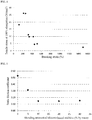
- FIG. 5 is a graph illustrating the relationship between the blending amount of the silicone-based additive and the static friction coefficient of the material of each filler layer according to each Example and Comparative Example.
- Material % by mass Material % by mass Coating state Static friction coefficient Physical properties of filler layer *11 Durability Breaking strain (%) Tensile stress at 100% elongation (N/mm 2 ) 1 min. 2 nin. 3 min. 4 min.
- Example 2 Water-based urethane resin* 3 100 - 0 Good 0.53 221 26 ⁇ ⁇ ⁇ ⁇ Example 7 Water-based urethane resin * 3 95 Silicone -based additive * 12 5 Good 0.31 230 25 ⁇ ⁇ ⁇ ⁇ Example 8 Water-based urethane resin * 3 90 Silicone -based additive * 12 10 Good 0.15 240 24 ⁇ ⁇ ⁇ ⁇ Example 9 Water-based urethane resin * 3 80 Silicone -based additive * 12 20 Sea-island shape 0.15 210 27 ⁇ ⁇ ⁇ ⁇ Example 10 Water-based urethane resin * 3 70 Silicone -based additive * 12 30 Sea-island shape 0.15 200 28 ⁇ ⁇ ⁇ *12) Acrylic-silicone graft polymer, US450 (solid content 30% by mass), manufactured by Toagosei Co., Ltd.
Landscapes
- Physics & Mathematics (AREA)
- General Physics & Mathematics (AREA)
- Engineering & Computer Science (AREA)
- General Engineering & Computer Science (AREA)
- Plasma & Fusion (AREA)
- Mechanical Engineering (AREA)
- Rolls And Other Rotary Bodies (AREA)
- Electrophotography Configuration And Component (AREA)
- Dry Development In Electrophotography (AREA)
Abstract
Description
- The present invention relates to a roller and an image formation device using the same (hereinafter, also simply referred to as a "device"), and in particular, to a conductive roller used in image formation devices such as copying machines, printers and in particular laser beam printers, and in particular to a roller suitable as a developing roller and an image formation device using the same.
- In general, in image formation devices using electrophotographic printing methods such as copying machines, printers, facsimiles, etc., rollers provided with electrical conductivity are used such as transfer rollers, developing rollers, toner supply rollers, electrification rollers, cleaning rollers, intermediate transfer rollers, belt driving rollers, etc. in each step of the image formation.
- As such a roller member, in order to obtain desired surface roughness, electrical conductivity and hardness etc., conventionally used is one that are provided with a layer or layers provided on the outer periphery of a basic structure which is a structure constituted by shaft on which an elastic layer is formed, the elastic layer being composed of rubber, polymeric elastomer, polymer foam, etc. which was given electrical conductivity by the combination of a conductive agent.
- As a technology relating to the improvement of the conductive roller, for example,
Patent document 1 describes a conductive roller having a core metal, a substrate provided on the surface thereof and a filler layer provided on the cylindrical surface of the substrate which is composed of conductive flexible polyurethane foam, wherein a release opening for a bubble of conductive flexible polyurethane foam in the cylindrical surface is blocked by the filler layer. - Patent Document 1: Japanese Unexamined Patent Publication No.
H9-262912 - Incidentally, when a developing roller is mounted on a cartridge, in order to keep a contact width (nip width) between the roller and a photo sensitizer constant, a ring-shaped member may be disposed coaxially with the roller at an axial end of the roller. In such cases, as a device is used, the ring-shaped member and the end of the roller come into contact and rub against each other, the end of the roller is scraped, and cut waste may be generated. When such cut waste is transferred to a photo sensitizer, paper, or the like in an image forming device, generation of an image failure is caused, which has been problematic.
- Accordingly, an object of the present invention is to provide a roller capable of suppressing generation of cut waste from an end of a roller due to contact with another member inside a device when mounted on an image forming device, particularly a conductive roller, and an image forming device using the same.
- The present inventor has intensively studied to find that the above-described problem can be solved by providing a filler layer made of a specific material on an axial end face of a roller, thereby completing the present invention.
- In other words, the roller according to the present invention is a roller comprising a shaft and a base layer provided on an outer periphery of the shaft, characterized in that
a filler layer covering the base layer is provided on end faces of both ends of the base layer in the roller axial direction, and the filler layer is composed of a material having a breaking strain measured according to a tensile test of JIS K 7127 of not less than 120% and a tensile stress at 100% elongation measured according to a tensile test of JIS K 7127 of from 5 to 30 N/mm2. - In the roller of the present invention, preferably, the material of the filler layer contains a water-based urethane resin. In the roller of the present invention, preferably, the material of the filler layer contains a silicone-based additive, particularly in an amount of from 5 to 30% by mass. Further, in the roller of the present invention, suitably, a film thickness of the filler layer is from 10 to 100 µm. Still further, the roller of the present invention is suitably a conductive roller.
- Further, the image forming device of the present invention is characterized in that the above-described roller of the present invention is mounted thereon.
- According to the present invention, by providing a filler layer composed of a material having predetermined physical properties on end faces of both ends of a base layer in the roller axial direction, it becomes possible to realize a roller capable of suppressing generation of cut waste from an end of a roller due to contact with another member inside a device when mounted on an image forming device, particularly a conductive roller, and an image forming device using the same.
-
-
FIG. 1 is a longitudinal cross-sectional view illustrating one configuration example of a roller of the present invention. -
FIG. 2 is a partial cross-sectional view illustrating one configuration example of an image forming device of the present invention. -
FIG. 3 is a schematic view illustrating a device used for durability evaluation in Examples. -
FIG. 4 is a graph illustrating a relationship between a breaking strain and a stress at 100% elongation in Examples. -
FIG. 5 is a graph illustrating a relationship between a blending amount of a silicone-based additive and a static friction coefficient in Examples. - Hereinafter, embodiments of the present invention will be described in detail with reference to the drawings.
-
FIG. 1 illustrates a longitudinal cross-sectional view of one example of a roller of the present invention. An illustratedroller 10 comprises ashaft 1, abase layer 2 supported on the outer periphery of theshaft 1, and one layer of afilm layer 3 covering the outer periphery of thebase layer 2. - The roller of the present invention has at least the
base layer 2 on the outer periphery of theshaft 1, and afiller layer 4 covering thebase layer 2 is provided on end faces of both ends of thebase layer 2 in the roller axial direction. In the present invention, thefiller layer 4 is characterized by being made of a material having a breaking strain of not less than 120% and a tensile stress at 100% elongation of from 5 to 30 N/mm2. - In the present invention, by providing the
filler layer 4 covering thebase layer 2 on an end face of the roller in the axial direction to protect the end face and eliminating the exposure of the end face, it becomes possible to suppress generation of cut waste from the end face of the roller even when the end face of the roller is in contact with another member such as a ring-shaped member in a device. Even in cases in which thefiller layer 4 is provided on the end face of the roller, when thefiller layer 4 itself is scraped off due to contact with other members, a problem of cut waste occurs again, and therefore, in the present invention, it is assumed that thefiller layer 4 is made of a material having the predetermined breaking strain and tensile stress and the strength of thefiller layer 4 is secured, thereby forming thefiller layer 4 which does not scrape even when the layer comes into contact with another member. - The material for forming the
filler layer 4 has a breaking strain of 120% or more, and preferably 200 to 400%, and has a tensile stress at 100% elongation of 5 to 30 N/mm2, and preferably 10 to 30 N/mm2. By using a material satisfying such physical properties, it is possible to form thefiller layer 4 having excellent durability, which does not scrape even when the layer comes into contact with another member. In cases in which the breaking strain is outside the above range, even when the tensile stress at 100% elongation satisfies the above range, the layer can not withstand a certain displacement or more and scraping occurs, and therefore, an expected effect of the present invention can not be obtained. In cases in which the tensile stress at 100% elongation is outside the above range, even when the breaking strain satisfies the above range, scraping occurs because the layer can not withstand a certain stress or more, and therefore, an expected effect of the present invention can not be obtained. Here, in the present invention, the breaking strain and the tensile stress at 100% elongation are values measured in accordance with a tensile test of JIS K 7127. - Specifically, in the present invention, it is preferable to form the
filler layer 4 using a material containing a water-based urethane resin from the viewpoint of securing strength and making scraping less likely to occur. In particular, as described below, when thebase layer 2 is formed of polyurethane foam, since thebase layer 2 and thefiller layer 4 using a water-based urethane resin have the same functional group, the compatibility thereof is good, and adhesiveness thereof become more favorable. This makes it possible to prevent occurrence of image defects caused by cut waste adhering to a photo sensitizer or the like inside the image forming device over a long period of time. - The water-based urethane resin is a self-emulsifying type obtained by emulsifying a urethane resin, and may be of any type, such as an ether-based, an ester-based, an ester/ether-based, and a carbonate-based, and from the viewpoint of adhesiveness to a roller end face and durability, an ester/ether-based or a carbonate-based is preferably used. The reason why a water-based urethane resin is used is that in a solvent system, a water-based urethane resin penetrates into the
foam layer 2 and swells thefoam layer 2. - The
filler layer 4 preferably contains a silicone-based additive. By adding a silicone-based additive to a water-based urethane resin, it is possible to reduce the coefficient of friction of the surface of thefiller layer 4 to be formed, making it difficult for the roller end part to be scraped, thereby further improving the durability. Specific examples of the silicone-based additive which can be used include acrylic-silicone graft polymer. The addition amount of the silicone-based additive is preferably from 5 to 30% by mass, and more preferably from 5 to 10% by mass in the material of the filler layer in solid content. In particular, by containing the silicone-based additive in an amount of 5 to 10% by mass, it is possible to provide thefiller layer 4 in a uniform coating state while sufficiently reducing the frictional force. - The
filler layer 4 can be formed by applying a coating liquid prepared by adding a silicone-based additive to a water-based urethane resin, as needed, to the end face using a dispenser, a stamp, a spray, a knife coater, or the like, then volatilizing, and curing. Specific examples of the coating method include a method of scratching and painting the paint supplied to the end face with a dispenser or the like with a doctor knife or the like and a method of spray painting on the end face, and as a heating method, a general method may be appropriately used. - Since the
filler layer 4 may cover at least the end face of thebase layer 2, thefiller layer 4 may be formed to have the same diameter as the outer diameter of the roller or a diameter of the outer diameter of thebase layer 2 or larger and smaller than the outer diameter of the roller. Specifically, for example, the roller may be formed with an outer diameter of [(outer diameter of the roller) - 0 µm to (outer diameter of the roller) - 250 µm], depending on the size of the roller. - The thickness of the
filling layer 4 may be any thickness as long as it can completely cover an end face of thebase layer 2, and is preferably from 10 to 100 µm. By setting the film thickness in this range, it is possible to accurately attach the roller to a mounting position when the roller is mounted on a cartridge, while securing the durability of thefiller layer 4. - In the present invention, only that at least a base layer is covered with a filler layer on the end face in the roller axial direction is important, and other aspects can be appropriately configured according to a conventional method, and are not particularly limited.
- For example, the
shaft 1 is not particularly limited as long as it has a good conductivity, and any shaft can be used. Examples thereof include a steel material such as sulfur free cutting steel plated with nickel, zinc or the like, a solid metal core made of a metal such as iron, stainless steel, aluminum or the like, a metallic shaft such as a metal cylindrical body hollowed out in the interior, a highly conductive plastic shaft, and the like. - The
base layer 2 is not particularly limited and can be formed of known rubber or resin, or a foam in which closed cells are dispersed therein. Specifically, thebase layer 2 can be formed from elastomer such as polyurethane, silicone rubber, ethylene-propylene-diene rubber (EPDM), acrylonitrile-butadiene rubber (NBR), natural rubber, styrene-butadiene rubber (SBR), butadiene rubber, isoprene rubber, polynorbornene rubber, butyl rubber, chloroprene rubber, acrylic rubber, epichlorohydrin rubber (ECO), ethylene-vinyl acetate copolymer (EVA) and the mixture thereof, and is suitably composed of polyurethane foam. According to the present invention, generation of a cut waste can be suppressed, and therefore, a roller using polyurethane foam excellent in image characteristics can be used without problems. The foam constituting thebase layer 2 is formed by foaming chemically the above-described elastomer with a foaming agent or by foaming it mechanically by involving air therein as in the case of polyurethane foam. - When the
base layer 2 is formed of foam, bubbles in the foam are suitably closed-cell bubbles since compression permanent deformation performance is improved. In order for bubbles in the foam to be closed-cell, the procedure of foaming the above-described elastomeric raw material by mechanical stirring of the foam is suitably adopted. - Raw polyurethane materials for forming the polyurethane foam which are suitably used for the
base layer 2 are not especially limited so long as they contain a urethane bond in the resin. As a polyisocyanate constituting the raw polyurethane material, aromatic isocyanate or the derivative thereof, aliphatic isocyanate or the derivative thereof, and alicyclic isocyanate or the derivative thereof are used. Aromatic isocyanate or the derivative thereof is preferable among them, and tolylenediisocyanate or the derivative thereof, and diphenylmethane diisocyanate or the derivative thereof are particularly suitably used. As tolylenediisocyanate or the derivative thereof, crude tolylenediisocyanate, 2,4-tolylenediisocyanate, 2,6-tolylenediisocyanate, the mixture of 2,4-tolylenediisocyanate and 2,6-tolylenediisocyanate, the urea modified products thereof, the biuret modified products thereof, the carbodiimide modified products thereof, and urethane product modified by polyol etc. are used. As diphenyl methane diisocyanate or the derivative thereof, for example, diphenylmethane diisocyanate or the derivative thereof, obtained by phosgenation of diaminodiphenylmethanes or the derivative thereof are used. The derivatives of diaminodiphenylmethane, include polynuclear products, and pure diphenylmethane diisocyanate obtained from diaminodiphenylmethane, polymeric diphenylmethane diisocyanates obtained from the polynuclear products of diaminodiphenylmethane can be used. As for the number of functional groups of polymeric diphenylmethane diisocyanate, a mixture of pure diphenylmethane diisocyanate and polymeric diphenyl methane diisocyanate having various numbers of functional groups is usually used, and a mixture having an averaged number of functional groups preferably from 2.05 to 4.00, more preferably from 2.50 to 3.50 are used. In addition, derivatives obtained by the modification of these diphenylmethane diisocyanates or derivatives thereof, for example, such as urethane modification products modified by polyol etc., dimers by uretdione formation, isocyanurate modification products, carbodiimide/uretonimine modification products, allophanate modification products, urea modification products, biuret modification products can be also used. Further, a blend of several kinds of diphenylmethane diisocyanates and the derivatives thereof can be also used. - Polyol components constituting raw polyurethane materials can be used which include polyether polyol from the addition polymerization of ethylene oxide with propylene oxide, polytetramethylene ether glycol, polyester polyol from the condensation of the acid component and the glycol component, polyester polyol from the ring-opening polymerization of caprolactone, and polycarbonate diol. Polyether polyol from the addition polymerization of ethylene oxide with propylene oxide include products from the addition polymerization of ethylene oxide with propylene oxide, for example, by using, as a starting material, water, propylene glycol, ethylene glycol, glycerin, trimethylolpropane, hexane triol, triethanolamine, diglycerine, pentaerythritol, ethylenediamine, methyl glucoside, aromatic diamine, sorbitol, sucrose, phosphoric acid, etc., and particularly suitable is a product from water, propylene glycol, ethylene glycol, glycerin, trimethylolpropane, hexane triol used as a starting material. As for the ratio and microstructure of added ethylene oxide and propylene oxide, the ratio of ethylene oxide is preferably from 2 to 95% by mass, more preferably from 5 to 90% by mass. In particular, the polyether polyol having ethylene oxide added on the terminal thereof is preferably used. The arrangement of ethylene oxide and propylene oxide in the molecular chain is preferably random. The molecular weight of this polyether polyol, bifunctional when obtained from water, propylene glycol and ethylene glycol as starting materials, is preferably in the range from 300 to 6000 by weight-average molecular weight, particularly preferably from 400 to 3000. The molecular weight of the polyether polyol, trifunctional when obtained from glycerin, trimethylolpropane and hexane triol as starting materials, is preferably in the range from 900 to 9000 by weight-average molecular weight, and particularly preferably from 1500 to 6000. A blend of the bifunctional polyol and the trifunctional polyol can be appropriately used.
- Polytetramethylene ether glycol is obtained, for example, from cationic polymerization of tetrahydrofuran, and the product having weight-average molecular weight in the range from 400 to 4000, particularly from 650 to 3000 is preferably used. It is also preferable to blend polytetramethylene ether glycols with different molecular weights. In addition, polytetramethylene ether glycols obtained from copolymerization of alkylene oxides such as ethylene oxide and propylene oxide can be also used. It is also preferable to use a blend of polytetramethylene ether glycol and polyether polyol from addition polymerization of ethylene oxide with propylene oxide, and in this case, it is preferably used so that the ratio of polytetramethylene ether glycol to polyether polyol from addition polymerization of ethylene oxide with propylene oxide is within the range from 95:5 to 20:80 by mass, and particularly from 90:10 to 50:50. Polymer polyol of acrylonitrile-modified polyol, polyol of melamine added to polyol, diols such as butane diol, polyols such as trimethylolpropane and the derivatives thereof can be used in combination with the above-mentioned polyol components.
- Polyol may be prepolymerized by polyisocyanate in advance, and the methods include a method in which polyol and polyisocyanate are put into a suitable vessel, sufficiently stirred and kept at 30 to 90°C, more preferably 40 to 70°C, for 6 to 240 hours, more preferably for 24 to 72 hours. In this case, the ratio of the quantities of polyol and polyisocyanate are preferably adjusted so that the isocyanate content ratio of the prepolymer to be obtained is from 4 to 30% by mass, more preferably from 6 to 15% by mass. If the isocyanate content ratio is less than 4% by mass, the stability of the prepolymer is damaged, and the prepolymer may be hardened during storage and not be able to be provided for use. When the isocyanate content ratio exceeds 30% by mass, polyisocyanate content that has not been prepolymerized increases, and since this polyisocyanate is hardened with polyol component to be used in a later polyurethane hardening reaction, via a reaction mechanism similar to a one-shot process that does not undergo prepolymerization reaction, the advantage of the prepolymer method is diminished. As polyol components, when isocyanate component is used which is in prepolymer of polyol prepolymerized in advance by polyisocyanate, diols such as ethylene glycol and butane diol, polyols such as trimethylolpropane and sorbitol, and the derivatives thereof can be used in addition to the above-mentioned polyol components.
- To the raw polyurethane material can be added a conductive agent such as an ionic conducting agent and an electro-conductive agent, a filler material such as carbon black and inorganic carbonate, an antioxidant such as phenol and phenylamine, a friction-reducing agent, and a charge adjustment agent, etc. Examples of the ionic conducting agent include ammonium salts such as perchlorate, chlorate, hydrochloride, bromate, iodate, fluoroborate, sulfate, ethylsulfonate, carboxylate, sulfonate of tetraethylammonium, tetrabutylammonium, dodecyltrimethylammonium (for example, lauryl trimethyl ammonium), hexadecyl trimethyl ammonium, octadecyl trimethyl ammonium (for example, stearyl trimethyl ammonium), benzyl trimethyl ammonium, modified fat dimethylethyl ammonium, etc., and perchlorate, chlorate, hydrochloride, bromate, iodate, fluoroborate, trifluoromethylsulfonate, sulfonate of alkali and alkaline earth metals such as lithium, sodium, potassium, calcium, magnesium. Examples of the electro-conductive agent include conductive carbons such as Ketjen black, acetylene black; carbons for rubber such as SAF, ISAF, HAF, FEF, GPF, SRF, FT, MT; oxidation-treated carbon for ink, thermal decomposition carbon, natural graphite, artificial graphite; electro-conductive metal oxides such as tin oxide, titanium oxide, zinc oxide; metals such as nickel, copper, silver, germanium. These conductive agents may be used alone or in a mixture of more than or equal to two of them. The blending amount thereof is not particularly limited and can be appropriately selected as desired, and the ratio is usually from 0.1 to 40 parts by mass, preferably from 0.3 to 20 parts by mass with respect to 100 parts by mass of the raw polyurethane material.
- Catalysts used in the hardening reaction of the raw polyurethane materials include monoamines such as triethylamine and dimethyl cyclohexylamine, diamines such as tetramethylethylene diamine, tetramethyl propane diamine and tetramethyl hexane diamine, triamines such as pentamethyldiethylene triamine, pentamethyldipropylene triamine, tetra-methylguanidine, cyclic amines such as triethylenediamine, dimethyl piperazine, methylethyl piperazine, methyl morpholine, dimethylaminoethyl morpholine, dimethyl imidazole, alcoholic amines such as dimethylamino ethanol, dimethylaminoethoxy ethanol, trimethylaminoethylethanol amine, methylhydroxyethyl piperazine, hydroxyethyl morpholine, ether amines such as bis(dimethylaminoethyl)ether, ethylene glycol bis(dimethyl)amino propyl ether, and organometallic compounds such as stannous octoate, dibutyl tin diacetate, dibutyl tin dilaurate, dibutyl tin mercaptide, dibutyl tin thiocarboxylate, dibutyl tin dimaleate, dioctyl tin mercaptide, dioctyl tin thiocarboxylate, phenyl mercury propionate, lead octenoate. These catalysts can be used alone or in combination of two or more of them.
- In the present invention, it is preferable that a silicone foam stabilizer and various surfactants are combined into the raw polyurethane materials for stabilizing the cells in the foam material. As the silicone foam stabilizer, dimethylpolysiloxane-polyoxyalkylene copolymer, or the like is suitably used, and particularly preferable is the copolymer having the dimethylpolysiloxane moiety of molecular weight from 350 to 15000 and the polyoxyalkylene moiety of molecular weight from 200 to 4000. As for the molecular structure of the polyoxyalkylene moiety, the addition polymer of ethylene oxide and the co-addition polymer of ethylene oxide and propylene oxide are preferable, and the molecular terminals of the polymers are also preferably ethylene oxide. The surfactants include ionic surfactants such as cationic surfactants, anionic surfactants and amphoteric surfactants, and non-ionic surfactants such as various polyethers and various polyesters. The blending amount of the silicone foam stabilizer and the various surfactants are preferably from 0.1 to 10 parts by mass, more preferably from 0.5 to 5 parts by mass to 100 parts by mass of the raw polyurethane material.
- The polyurethane foam used in the present invention preferably has a density within the range from 0.1 to 0.7 g/cm3, more preferably from 0.50 to 0.65 g/cm3. Too low and too high densities are both undesirable because the too low density leads to the coarsening of the bubble, and the too high density leads to the worsening of roller performance.
- The ASKER C hardness of the polyurethane foam is preferably from 15 to 70°, more preferably from 15 to 45°. In the present invention, the mechanical floss method, the water foaming method, the foaming agent floss method, etc., which are conventionally used, can be used as a method of foaming in advance the raw polyurethane material, and the mechanical floss method, which performs foaming by mechanical stirring while mixing inactive gas, is preferably used regarding obtaining polyurethane foam of the closed-cell foam structure having a suitable density and hardness. Any inactive gasses used in the mechanical floss method are acceptable so long as they are inactive gas in polyurethane reaction, and include gasses non-reactive to the raw polyurethane materials such as nitrogen, carbon dioxide and dry air as well as inactive gasses in a narrow sense such as helium, argon, xenon, radon and krypton. By injecting the foamed raw polyurethane material into a metal mold, followed by the hardening thereof, polyurethane foam can be obtained which has self-skin layer (thin stratified film) formed on the part of the foam in contact to the metal mold. At that time, a method of coating with fluoro-resin etc. the inner surface of the metal mold can give mold-releasing property to the metal mold.
- The molding conditions of the
base layer 2 composed of polyurethane form is not particularly limited and can be obey usually conditions, and for example, thebase layer 2 can be obtained by starting the foaming of the raw polyurethane material at a temperature within the range from 15 to 80°C, preferably from 20 to 65°C, and completing injection into the metal mold in whichshaft 1 is placed, and then performing cure at a temperature from about 70 to 120°C, followed by removal of the product from the mold. - In the present invention, at least one film layer can be formed on the outer periphery of the
base layer 2. Although in an example depicted inFIG. 1 onefilm layer 3 as a surface layer forming a roller surface is provided on the outer periphery of thebase layer 2, two film layers of an intermediate layer and a surface layer can be also provided without limitation, and moreover, other functional layers may be added. - For example, the surface layer can be formed by solvent-based paints such as urethane-based, acrylic-based, acrylic urethane-based and fluorine-based ones, and the surface roughness of the layer can be adjusted by containing spherical microparticles made of urethane, acryl, silica, etc. The surface roughness of such a surface layer is usually less than or equal to 2 µm, particularly preferably within the range from 0.5 to 1.5 µm based on the JIS arithmetic average roughness Ra. Desired electrical conductivity can be given by appropriately containing the above-mentioned ionic conductive agent and the electron conductive agent as a conductive agent. Although the thickness of the surface layer is not particularly limited, it may be usually from 1 to 50 µm, particularly from about 1 to about 40 µm.
- The intermediate layer may be a water-based paint containing a conductive agent, and any one or at least two types selected from the group consisting of rubber-based, urethane-based and acrylic-based paints can be suitably used as the water-based paint. Latex such as natural rubber (NR), chloroprene rubber (CR), nitrile rubber (NBR) and styrene-butadiene rubber (SBR) can be appropriately used as the rubber-based paint, ether-based, ester-based emulsions and dispersions as the urethane-based paint, and acryl, acrylic styrene emulsions etc. as the acrylic-based paint. The same conductive agents as those mentioned above with respect to the
base layer 2 can be used as conductive agents contained in the paints without particular limitation. In addition, vulcanizers, vulcanization enhancers, rubber antioxidants, and the like can be appropriately added to the intermediate layer as desired. - The thickness of the intermediate layer is usually within the range from 10 to 100 µm, particularly from 30 to 80 µm. When the thickness is less than 10 µm, the solvent shielding effect for the base layer and the filler effect for preventing oozing of contaminant from the lower layer side become insufficient, resulting in solvent erosion that makes impossible to provide a desired surface roughness. On the other hand, when the thickness exceeds 100 µm, the intermediate layer cannot follow the softness of the
base layer 2, causing a crack and a peeling, the hardening of the roller itself, which could lead to a defect relating to the roller performance such as toner damage. - The intermediate layer can be formed into one or at least two layers by applying the above-mentioned water-based paint onto
base layer 2. Well-known procedures can be used as methods of coating the intermediate layer, which include, but are not limited to, dip coating, spray coating and roll-coater coating, and dip coating is suitably used. The micro hardness of the intermediate layer is suitably within the range from10 to 45° for the film thickness of 500 µm, and the hardness roughly within this range can realize desired roller hardness for the finally obtained roller surface. The micro hardness can be measured, for example, by Micro Durometer Model MD-1. - The roller of the present invention is suitable as a conductive roller used in electrophotographic image forming devices etc. and can be suitably used specifically, for example, as various roller members such as developing rollers, electrification rollers, transfer rollers, toner supply rollers and cleaning rollers, and is particularly useful as a developing roller.
- The roller of the present invention can be manufactured as follows: At first, a base layer is formed on the outer periphery of a shaft by molding; Then, as desired, at least one film layer, specifically for example, the above-mentioned surface layer is directly formed, or an intermediate layer and the surface layer are sequentially formed by coating on the formed base layer; Then, as desired, the formed base layer and the film layer are cut at the both ends of the roller in the axial direction thereof, wherein cases of cutting the base layer and the film layer at the both ends of the roller in the axial direction thereof include a case of cutting the end parts of the roller expanded by molding and a case of adjusting the size of the roller from the view point of the appearance of the roller; Then, by the above-mentioned techniques, the filler layer in a size enough to cover at least the base layer is provided on end faces of both ends of the base layer and the film layer in the roller axial direction or the cut surfaces of the cut base and film layers, and thus the roller of the present invention can be obtained.
- Further, the image forming device of the present invention is characterized in that the roller of the above present invention, especially the conductive roller, the developing roller among others is mounted thereon, thereby enabling to solve the problem of the occurrence of an image defect due to the attachment of cut waste onto photo sensitizer etc.
FIG. 2 depicts a partial cross-sectional view of an example of the image forming device of the present invention. In the illustrated image forming device of the present invention, there are provided animage forming body 21, such as photo sensitizer, retaining an electrostatic latent image, a developingroller 10, in contact to theimage forming body 21, for visualizing the electrostatic latent image by the adhesion oftoner 20 supported on the surface of the roller thereto, and atoner supply roller 22 for supplying thetoner 20 to the developingroller 10, and image formation is performed by a series of processes which convey thetoner 20 from atoner container 23 via thetoner supply roller 22 and the developingroller 10 to theimage forming body 21. - In the illustrated image forming device, the
image forming body 21 is electrified to a constant potential by anelectrification roller 25, and then, an electrostatic latent image is formed on theimage forming body 21 by an exposure device (not illustrated). Then, by the rotation of thetoner supply roller 22, the developingroller 10 and theimage forming body 21 in the direction of the arrow in the figure, thetoner 20 ontoner supply roller 22 is sent via the developingroller 10 to theimage forming body 21. Thetoner 20 on the developingroller 10 is shaped into a uniform thin layer by alayering blade 24, and by the rotation of the developingroller 10 and theimage forming body 21 in contact with each other, thetoner 20 from developingroller 10 adheres to the electrostatic latent image in theimage forming body 21, resulting in the visualization of the latent image. Thetoner 20 adhering to the latent image is transferred by thetransfer roller 26 to recording medium such as paper, and thetoner 20 remaining on theimage forming body 21 after the transfer is removed by acleaning blade 28 in acleaning part 27. The image formation device of the present invention may be further provided with well-known compartments (not illustrated) used in conventional image forming devices. - The present invention will now be described in detail by using Examples.
- First of all, polyurethane foam was supported on the outer periphery of a shaft (ø 6 mm, 260 mm in length, material type: sulfur free cutting steel) by the mechanical floss method. The density of this polyurethane foam was 0.60 g/cm3.
- In particular, a raw polyurethane material composed of an isocyanate component (prepolymerized isocyanate TDI + polyether polyol) of 100 parts by mass and a polyol component (polyether polyol) of 20 parts by mass, carbon-black (acetylene black) of 2 parts by mass, an ionic conducting agent (sodium perchlorate) of 0.2 parts by mass was prepared, and this raw polyurethane material was mechanically stirred, mixed with dry air by mixier, and foamed. The polyurethane-foam material was injected into a metal cylindrical split mold which was provided with a hole provided at the end thereof for penetrating the shaft and a metal cap placed for supporting the shaft. Inside the mold, the shaft was placed, with adhesive applied onto the outer periphery thereof. Then, the mold with polyurethane-foam material injected therein was left in a hot wind oven adjusted to be at 110°C for one hour to allow the polyurethane-foam material to harden.
- The hardened polyurethane foam was released from the mold and dip-coated with CR rubber latex paint combined with carbon black (Ketjen black) to form an intermediate layer of a film thickness of 60 µm on the outer periphery of the base layer. Then, the foam was dip-coated with polyurethane solvent-based paint combined with spherical polyurethane particles of D50 = 10 µm and carbon black (acetylene black) to form a surface layer of a film thickness of 15 µm.
- The roller body of the roller obtained above was cut at both ends of the roller in the axial direction thereof so that the size of the roller body was ø 11.5 mm and 240 mm in length. Then, on the cut surface of the roller body, each of the filler layers described in the following Table having a film thickness of 50 µm was formed to obtain the sample rollers of Examples. The filler layers were formed within the cut surface of ø11.5 mm by a seal coating (a transfer method by a seal-shaped jig) followed by heating.
- Using the device illustrated in
FIG. 3 , the durability of cases in which a filler layer of each sample roller contacted and collided with another member in the device was evaluated. Specifically, with respect to anend part 30E of the roller body where a filler layer of eachsample roller 30 was formed, a ring-shaped member 31 (inner diameter: 6 mm, outer diameter: 11.5 mm) made of polyacetal (POM) resin commonly used as a commercially available printer material was pressed with a load F of 1.5 N, and each sample roller was rotated at 200 rpm to evaluate the generation of scraping of the filler layer with elapsed time.Reference numeral 32 in the drawing indicates a motor. Evaluation criteria are as follows. The results are listed on the following table. - ○: The filler layer and the substrate were intact.
- Δ: The filler layer is beginning to be removed.
- ×: Waste is generated due to scraping of the substrate.
- The relationship between the breaking strain and the tensile stress at 100% elongation of the material of each filler layer according to each Example and Comparative Example is illustrated in a graph of
FIG. 4 . - As listed on the above table, a sample roller of each Example provided with a filler layer using a material satisfying conditions according to the present invention had no damage on the filler layer and the roller body for 3 minutes or more even in the durability test, it was thereby confirmed that generation of cut waste can be suppressed.
- Next, using a water-based urethane resin (ester/ether urethane, SUPERFLEX 150, manufactured by DKS Co., Ltd.) and silicone-based additive (US450, manufactured by Toagosei Co., Ltd.) in a blending amount (based on solid content) listed on the following table, a filler layer was formed with a film thickness of 50 µm in the same manner as above to prepare a sample roller of each Example.
- With respect to each of the obtained sample rollers, the coating state of the filler layer was visually observed, and the static friction coefficient of the surface of the filler layer was measured three times, and the average value thereof was determined.
- Using the apparatus illustrated in
FIG. 3 , the durability in cases in which the filler layer of each sample roller contacted and collided with another member in a device was evaluated in the same manner as described above. The results are listed in combination on the table below.FIG. 5 is a graph illustrating the relationship between the blending amount of the silicone-based additive and the static friction coefficient of the material of each filler layer according to each Example and Comparative Example.[Table 2] Material % by mass Material % by mass Coating state Static friction coefficient Physical properties of filler layer *11 Durability Breaking strain (%) Tensile stress at 100% elongation (N/mm2) 1 min. 2 nin. 3 min. 4 min. Example 2 Water-based urethane resin*3 100 - 0 Good 0.53 221 26 ○ ○ ○ Δ Example 7 Water-based urethane resin *3 95 Silicone -based additive *12 5 Good 0.31 230 25 ○ ○ ○ Δ Example 8 Water-based urethane resin *3 90 Silicone -based additive *12 10 Good 0.15 240 24 ○ ○ ○ ○ Example 9 Water-based urethane resin *3 80 Silicone -based additive *12 20 Sea-island shape 0.15 210 27 ○ ○ ○ ○ Example 10 Water-based urethane resin *3 70 Silicone -based additive *12 30 Sea-island shape 0.15 200 28 ○ ○ ○ ○ *12) Acrylic-silicone graft polymer, US450 ( solid content 30% by mass), manufactured by Toagosei Co., Ltd. - As listed on the above table, it was confirmed that when a silicone-based additive was added to the water-based urethane resin in the filler layer, the friction coefficient was reduced, and the durability was improved accordingly. On the other hand, it was found that a urethane component and a silicone component were separated when the amount of the silicone-based additive was increased, and the coating state deteriorated.
-
- 1
- shaft
- 2
- base layer
- 3
- film layer
- 4
- filler layer
- 10
- roller (developing roller)
- 20
- toner
- 21
- image forming body
- 22
- toner supply roller
- 23
- toner container
- 24
- layering blade
- 25
- electrification roller
- 26
- transfer roller
- 27
- cleaning part
- 28
- cleaning blade
- 30
- sample roller
- 30E
- end part of roller body
- 31
- ring-shaped member
- 32
- motor
| Material | Physical properties of filler layer *11 | Durability | |||||
| Breaking stress (N/mm2) | Breaking strain (%) | Tensile stress at 100% elongation (N/mm2) | |||||
| 1 min. | 2 min. | 3 min. | |||||
| Comparative Example 1 | Water-based urethane resin *1 | 13 | 1500 | 2.6 | × | × | × |
| Example 1 | Water-based urethane resin *2 | 50 | 262 | 26 | ○ | ○ | ○ |
| Example 2 | Water-based urethane resin *3 | 44 | 221 | 26 | ○ | ○ | ○ |
| Comparative Example 2 | Water-based urethane resin *4 | 33 | 512 | 4.9 | ○ | Δ | × |
| Example 3 | Water-based urethane resin *5 | 20 | 122 | 18 | ○ | ○ | ○ |
| Example 4 | Water-based urethane resin *6 | 47 | 320 | 11 | ○ | ○ | ○ |
| Example 5 | Water-based urethane resin *7 | 48 | 340 | 9.8 | ○ | ○ | ○ |
| Comparative Example 3 | Acrylic resin *8 | 14 | 454 | 4.5 | ○ | Δ | × |
| Example 6 | Water-based urethane resin *9 | 17 | 430 | 9.8 | ○ | ○ | ○ |
| Comparative Example 4 | Water-based urethane resin *10 | 60 | 5 | Unmeasurable | ○ | × | × |
| *1) Urethane emulsion, SUPERFLEX 300 ( *2) Urethane emulsion, SUPERFLEX 150HS (solid content 38% by mass), manufactured by DKS Co. Ltd. *3) Ester/ether-based urethane, SUPERFLEX 150 ( *4) Urethane emulsion, SUPERFLEX 470 (solid content 38% by mass), manufactured by DKS Co. Ltd. *5) Urethane emulsion ( *6) Urethane emulsion ( *7) Carbonate-based urethane ( *8) Acrylic resin ( *9) Urethane emulsion ( *10) Urethane emulsion, SUPERFLEX 210 ( *11) The breaking stress, breaking strain, and tensile stress at 100% elongation of a material of each filler layer, measured in accordance with a tensile test of JIS K 7127. |
Claims (7)
- A roller comprising a shaft and a base layer provided on an outer periphery of the shaft, characterized in that
a filler layer covering the base layer is provided on end faces of both ends of the base layer in the roller axial direction, and the filler layer is composed of a material having a breaking strain measured according to a tensile test of JIS K 7127 of not less than 120% and a tensile stress at 100% elongation measured according to a tensile test of JIS K 7127 of from 5 to 30 N/mm2. - The roller according to claim 1, wherein the material of the filler layer contains a water-based urethane resin.
- The roller according to claim 1, wherein the material of the filler layer contains a silicone-based additive.
- The roller according to claim 3, wherein the material of the filler layer contains the silicone-based additive in an amount of from 5 to 30% by mass.
- The roller according to claim 1, wherein a film thickness of the filler layer is from 10 to 100 µm.
- The roller according to claim 1 which is a conductive roller.
- An image forming device is characterized in that the roller according to claim 1 is mounted thereon.
Applications Claiming Priority (2)
| Application Number | Priority Date | Filing Date | Title |
|---|---|---|---|
| JP2014179987A JP6363435B2 (en) | 2014-09-04 | 2014-09-04 | Roller and image forming apparatus using the same |
| PCT/JP2015/074367 WO2016035691A1 (en) | 2014-09-04 | 2015-08-28 | Roller and image forming apparatus using same |
Publications (3)
| Publication Number | Publication Date |
|---|---|
| EP3190466A1 true EP3190466A1 (en) | 2017-07-12 |
| EP3190466A4 EP3190466A4 (en) | 2017-09-13 |
| EP3190466B1 EP3190466B1 (en) | 2018-10-10 |
Family
ID=55439754
Family Applications (1)
| Application Number | Title | Priority Date | Filing Date |
|---|---|---|---|
| EP15838890.0A Not-in-force EP3190466B1 (en) | 2014-09-04 | 2015-08-28 | Roller and image forming apparatus using same |
Country Status (5)
| Country | Link |
|---|---|
| US (1) | US9874832B2 (en) |
| EP (1) | EP3190466B1 (en) |
| JP (1) | JP6363435B2 (en) |
| CN (1) | CN106605176A (en) |
| WO (1) | WO2016035691A1 (en) |
Families Citing this family (3)
| Publication number | Priority date | Publication date | Assignee | Title |
|---|---|---|---|---|
| EP3413136B1 (en) * | 2016-02-01 | 2021-11-10 | Bridgestone Corporation | Charging roller |
| WO2019003901A1 (en) * | 2017-06-27 | 2019-01-03 | Nok株式会社 | Developing roller |
| JP2020144225A (en) * | 2019-03-06 | 2020-09-10 | 株式会社リコー | Intermediate transfer belt, image forming apparatus, and image forming method |
Family Cites Families (14)
| Publication number | Priority date | Publication date | Assignee | Title |
|---|---|---|---|---|
| JPH0633478Y2 (en) * | 1987-06-09 | 1994-08-31 | 東海ゴム工業株式会社 | Roll |
| JP3326966B2 (en) * | 1994-06-13 | 2002-09-24 | 東海ゴム工業株式会社 | Conductive roll |
| JPH09262912A (en) * | 1996-03-28 | 1997-10-07 | Inoac Corp | Electroconducting roller and its manufacture |
| JP3511835B2 (en) * | 1997-03-12 | 2004-03-29 | 東海ゴム工業株式会社 | Manufacturing method of toner supply roll |
| JP3022859B1 (en) * | 1998-12-16 | 2000-03-21 | 株式会社金陽社 | Conductive roll and manufacturing method thereof |
| US6572791B2 (en) | 1999-12-10 | 2003-06-03 | Bridgestone Corporation | Electroconductive elastic member, elastic member and image formation equipment |
| JP2002053639A (en) * | 1999-12-10 | 2002-02-19 | Bridgestone Corp | Conductive elastic member and image forming apparatus |
| JP4407222B2 (en) * | 2003-09-29 | 2010-02-03 | 富士ゼロックス株式会社 | Developing roll, developing roll substrate, developing roll manufacturing method, and image forming apparatus |
| JP2007147857A (en) * | 2005-11-25 | 2007-06-14 | Konica Minolta Business Technologies Inc | Roller for developing device |
| JP5143355B2 (en) * | 2005-11-29 | 2013-02-13 | 東海ゴム工業株式会社 | Developing roll |
| JP4657263B2 (en) * | 2007-07-17 | 2011-03-23 | 株式会社ブリヂストン | Developing roller |
| JP5512167B2 (en) * | 2009-04-27 | 2014-06-04 | 株式会社ブリヂストン | Charge-controlled urethane foam and toner conveying roller using the same |
| JP6070201B2 (en) * | 2013-01-11 | 2017-02-01 | 株式会社リコー | Toner carrier |
| CN105027007A (en) * | 2013-03-05 | 2015-11-04 | 株式会社普利司通 | Roller, method for manufacturing same and image forming device using same |
-
2014
- 2014-09-04 JP JP2014179987A patent/JP6363435B2/en not_active Expired - Fee Related
-
2015
- 2015-08-28 EP EP15838890.0A patent/EP3190466B1/en not_active Not-in-force
- 2015-08-28 WO PCT/JP2015/074367 patent/WO2016035691A1/en not_active Ceased
- 2015-08-28 CN CN201580047609.7A patent/CN106605176A/en active Pending
- 2015-08-28 US US15/507,953 patent/US9874832B2/en active Active
Also Published As
| Publication number | Publication date |
|---|---|
| CN106605176A (en) | 2017-04-26 |
| EP3190466B1 (en) | 2018-10-10 |
| US9874832B2 (en) | 2018-01-23 |
| EP3190466A4 (en) | 2017-09-13 |
| JP2016053672A (en) | 2016-04-14 |
| WO2016035691A1 (en) | 2016-03-10 |
| JP6363435B2 (en) | 2018-07-25 |
| US20170308000A1 (en) | 2017-10-26 |
Similar Documents
| Publication | Publication Date | Title |
|---|---|---|
| JP4662249B2 (en) | Developing roller | |
| EP2151719B1 (en) | Electrically conductive roller | |
| JP6423553B2 (en) | Coating composition for conductive roller, developing roller and image forming apparatus using the same | |
| EP3474078A1 (en) | Conductive roller | |
| EP3190466B1 (en) | Roller and image forming apparatus using same | |
| EP3190300B1 (en) | Roller and image forming apparatus using same | |
| EP2966508A1 (en) | Roller, method for manufacturing same and image forming device using same | |
| US11314180B2 (en) | Charging roller | |
| JP5025983B2 (en) | Developing roller and image forming apparatus having the same | |
| JP5204953B2 (en) | Developing roller and image forming apparatus having the same | |
| JP4678766B2 (en) | Conductive roller | |
| CN112782950A (en) | Developing roller | |
| JP5041142B2 (en) | Conductive roller and method of manufacturing conductive roller | |
| CN112540520B (en) | Developing roller | |
| JP2007298662A (en) | Developing roller and image forming apparatus equipped with the same | |
| JP2008203571A (en) | Charging roller |
Legal Events
| Date | Code | Title | Description |
|---|---|---|---|
| STAA | Information on the status of an ep patent application or granted ep patent |
Free format text: STATUS: THE INTERNATIONAL PUBLICATION HAS BEEN MADE |
|
| PUAI | Public reference made under article 153(3) epc to a published international application that has entered the european phase |
Free format text: ORIGINAL CODE: 0009012 |
|
| STAA | Information on the status of an ep patent application or granted ep patent |
Free format text: STATUS: REQUEST FOR EXAMINATION WAS MADE |
|
| 17P | Request for examination filed |
Effective date: 20170322 |
|
| AK | Designated contracting states |
Kind code of ref document: A1 Designated state(s): AL AT BE BG CH CY CZ DE DK EE ES FI FR GB GR HR HU IE IS IT LI LT LU LV MC MK MT NL NO PL PT RO RS SE SI SK SM TR |
|
| AX | Request for extension of the european patent |
Extension state: BA ME |
|
| A4 | Supplementary search report drawn up and despatched |
Effective date: 20170811 |
|
| RIC1 | Information provided on ipc code assigned before grant |
Ipc: G03G 15/16 20060101ALI20170807BHEP Ipc: G03G 21/00 20060101ALI20170807BHEP Ipc: F16C 13/00 20060101ALI20170807BHEP Ipc: G03G 15/02 20060101ALI20170807BHEP Ipc: G03G 15/08 20060101AFI20170807BHEP Ipc: G03G 15/00 20060101ALI20170807BHEP |
|
| DAV | Request for validation of the european patent (deleted) | ||
| DAX | Request for extension of the european patent (deleted) | ||
| GRAP | Despatch of communication of intention to grant a patent |
Free format text: ORIGINAL CODE: EPIDOSNIGR1 |
|
| STAA | Information on the status of an ep patent application or granted ep patent |
Free format text: STATUS: GRANT OF PATENT IS INTENDED |
|
| INTG | Intention to grant announced |
Effective date: 20180518 |
|
| RIN1 | Information on inventor provided before grant (corrected) |
Inventor name: FUJISAWA YUSUKE |
|
| GRAS | Grant fee paid |
Free format text: ORIGINAL CODE: EPIDOSNIGR3 |
|
| GRAA | (expected) grant |
Free format text: ORIGINAL CODE: 0009210 |
|
| STAA | Information on the status of an ep patent application or granted ep patent |
Free format text: STATUS: THE PATENT HAS BEEN GRANTED |
|
| AK | Designated contracting states |
Kind code of ref document: B1 Designated state(s): AL AT BE BG CH CY CZ DE DK EE ES FI FR GB GR HR HU IE IS IT LI LT LU LV MC MK MT NL NO PL PT RO RS SE SI SK SM TR |
|
| REG | Reference to a national code |
Ref country code: GB Ref legal event code: FG4D |
|
| REG | Reference to a national code |
Ref country code: CH Ref legal event code: EP Ref country code: AT Ref legal event code: REF Ref document number: 1051958 Country of ref document: AT Kind code of ref document: T Effective date: 20181015 |
|
| REG | Reference to a national code |
Ref country code: IE Ref legal event code: FG4D |
|
| REG | Reference to a national code |
Ref country code: DE Ref legal event code: R096 Ref document number: 602015018087 Country of ref document: DE |
|
| REG | Reference to a national code |
Ref country code: NL Ref legal event code: MP Effective date: 20181010 |
|
| REG | Reference to a national code |
Ref country code: LT Ref legal event code: MG4D |
|
| REG | Reference to a national code |
Ref country code: AT Ref legal event code: MK05 Ref document number: 1051958 Country of ref document: AT Kind code of ref document: T Effective date: 20181010 |
|
| PG25 | Lapsed in a contracting state [announced via postgrant information from national office to epo] |
Ref country code: NL Free format text: LAPSE BECAUSE OF FAILURE TO SUBMIT A TRANSLATION OF THE DESCRIPTION OR TO PAY THE FEE WITHIN THE PRESCRIBED TIME-LIMIT Effective date: 20181010 |
|
| PG25 | Lapsed in a contracting state [announced via postgrant information from national office to epo] |
Ref country code: LV Free format text: LAPSE BECAUSE OF FAILURE TO SUBMIT A TRANSLATION OF THE DESCRIPTION OR TO PAY THE FEE WITHIN THE PRESCRIBED TIME-LIMIT Effective date: 20181010 Ref country code: AT Free format text: LAPSE BECAUSE OF FAILURE TO SUBMIT A TRANSLATION OF THE DESCRIPTION OR TO PAY THE FEE WITHIN THE PRESCRIBED TIME-LIMIT Effective date: 20181010 Ref country code: HR Free format text: LAPSE BECAUSE OF FAILURE TO SUBMIT A TRANSLATION OF THE DESCRIPTION OR TO PAY THE FEE WITHIN THE PRESCRIBED TIME-LIMIT Effective date: 20181010 Ref country code: FI Free format text: LAPSE BECAUSE OF FAILURE TO SUBMIT A TRANSLATION OF THE DESCRIPTION OR TO PAY THE FEE WITHIN THE PRESCRIBED TIME-LIMIT Effective date: 20181010 Ref country code: IS Free format text: LAPSE BECAUSE OF FAILURE TO SUBMIT A TRANSLATION OF THE DESCRIPTION OR TO PAY THE FEE WITHIN THE PRESCRIBED TIME-LIMIT Effective date: 20190210 Ref country code: NO Free format text: LAPSE BECAUSE OF FAILURE TO SUBMIT A TRANSLATION OF THE DESCRIPTION OR TO PAY THE FEE WITHIN THE PRESCRIBED TIME-LIMIT Effective date: 20190110 Ref country code: BG Free format text: LAPSE BECAUSE OF FAILURE TO SUBMIT A TRANSLATION OF THE DESCRIPTION OR TO PAY THE FEE WITHIN THE PRESCRIBED TIME-LIMIT Effective date: 20190110 Ref country code: PL Free format text: LAPSE BECAUSE OF FAILURE TO SUBMIT A TRANSLATION OF THE DESCRIPTION OR TO PAY THE FEE WITHIN THE PRESCRIBED TIME-LIMIT Effective date: 20181010 Ref country code: ES Free format text: LAPSE BECAUSE OF FAILURE TO SUBMIT A TRANSLATION OF THE DESCRIPTION OR TO PAY THE FEE WITHIN THE PRESCRIBED TIME-LIMIT Effective date: 20181010 Ref country code: LT Free format text: LAPSE BECAUSE OF FAILURE TO SUBMIT A TRANSLATION OF THE DESCRIPTION OR TO PAY THE FEE WITHIN THE PRESCRIBED TIME-LIMIT Effective date: 20181010 |
|
| PG25 | Lapsed in a contracting state [announced via postgrant information from national office to epo] |
Ref country code: GR Free format text: LAPSE BECAUSE OF FAILURE TO SUBMIT A TRANSLATION OF THE DESCRIPTION OR TO PAY THE FEE WITHIN THE PRESCRIBED TIME-LIMIT Effective date: 20190111 Ref country code: AL Free format text: LAPSE BECAUSE OF FAILURE TO SUBMIT A TRANSLATION OF THE DESCRIPTION OR TO PAY THE FEE WITHIN THE PRESCRIBED TIME-LIMIT Effective date: 20181010 Ref country code: PT Free format text: LAPSE BECAUSE OF FAILURE TO SUBMIT A TRANSLATION OF THE DESCRIPTION OR TO PAY THE FEE WITHIN THE PRESCRIBED TIME-LIMIT Effective date: 20190210 Ref country code: SE Free format text: LAPSE BECAUSE OF FAILURE TO SUBMIT A TRANSLATION OF THE DESCRIPTION OR TO PAY THE FEE WITHIN THE PRESCRIBED TIME-LIMIT Effective date: 20181010 Ref country code: RS Free format text: LAPSE BECAUSE OF FAILURE TO SUBMIT A TRANSLATION OF THE DESCRIPTION OR TO PAY THE FEE WITHIN THE PRESCRIBED TIME-LIMIT Effective date: 20181010 |
|
| REG | Reference to a national code |
Ref country code: DE Ref legal event code: R097 Ref document number: 602015018087 Country of ref document: DE |
|
| PG25 | Lapsed in a contracting state [announced via postgrant information from national office to epo] |
Ref country code: DK Free format text: LAPSE BECAUSE OF FAILURE TO SUBMIT A TRANSLATION OF THE DESCRIPTION OR TO PAY THE FEE WITHIN THE PRESCRIBED TIME-LIMIT Effective date: 20181010 Ref country code: CZ Free format text: LAPSE BECAUSE OF FAILURE TO SUBMIT A TRANSLATION OF THE DESCRIPTION OR TO PAY THE FEE WITHIN THE PRESCRIBED TIME-LIMIT Effective date: 20181010 Ref country code: IT Free format text: LAPSE BECAUSE OF FAILURE TO SUBMIT A TRANSLATION OF THE DESCRIPTION OR TO PAY THE FEE WITHIN THE PRESCRIBED TIME-LIMIT Effective date: 20181010 |
|
| PLBE | No opposition filed within time limit |
Free format text: ORIGINAL CODE: 0009261 |
|
| STAA | Information on the status of an ep patent application or granted ep patent |
Free format text: STATUS: NO OPPOSITION FILED WITHIN TIME LIMIT |
|
| PG25 | Lapsed in a contracting state [announced via postgrant information from national office to epo] |
Ref country code: RO Free format text: LAPSE BECAUSE OF FAILURE TO SUBMIT A TRANSLATION OF THE DESCRIPTION OR TO PAY THE FEE WITHIN THE PRESCRIBED TIME-LIMIT Effective date: 20181010 Ref country code: SK Free format text: LAPSE BECAUSE OF FAILURE TO SUBMIT A TRANSLATION OF THE DESCRIPTION OR TO PAY THE FEE WITHIN THE PRESCRIBED TIME-LIMIT Effective date: 20181010 Ref country code: SM Free format text: LAPSE BECAUSE OF FAILURE TO SUBMIT A TRANSLATION OF THE DESCRIPTION OR TO PAY THE FEE WITHIN THE PRESCRIBED TIME-LIMIT Effective date: 20181010 Ref country code: EE Free format text: LAPSE BECAUSE OF FAILURE TO SUBMIT A TRANSLATION OF THE DESCRIPTION OR TO PAY THE FEE WITHIN THE PRESCRIBED TIME-LIMIT Effective date: 20181010 |
|
| 26N | No opposition filed |
Effective date: 20190711 |
|
| PG25 | Lapsed in a contracting state [announced via postgrant information from national office to epo] |
Ref country code: SI Free format text: LAPSE BECAUSE OF FAILURE TO SUBMIT A TRANSLATION OF THE DESCRIPTION OR TO PAY THE FEE WITHIN THE PRESCRIBED TIME-LIMIT Effective date: 20181010 |
|
| PGFP | Annual fee paid to national office [announced via postgrant information from national office to epo] |
Ref country code: GB Payment date: 20190821 Year of fee payment: 5 |
|
| PG25 | Lapsed in a contracting state [announced via postgrant information from national office to epo] |
Ref country code: TR Free format text: LAPSE BECAUSE OF FAILURE TO SUBMIT A TRANSLATION OF THE DESCRIPTION OR TO PAY THE FEE WITHIN THE PRESCRIBED TIME-LIMIT Effective date: 20181010 |
|
| PG25 | Lapsed in a contracting state [announced via postgrant information from national office to epo] |
Ref country code: LI Free format text: LAPSE BECAUSE OF NON-PAYMENT OF DUE FEES Effective date: 20190831 Ref country code: MC Free format text: LAPSE BECAUSE OF FAILURE TO SUBMIT A TRANSLATION OF THE DESCRIPTION OR TO PAY THE FEE WITHIN THE PRESCRIBED TIME-LIMIT Effective date: 20181010 Ref country code: CH Free format text: LAPSE BECAUSE OF NON-PAYMENT OF DUE FEES Effective date: 20190831 Ref country code: LU Free format text: LAPSE BECAUSE OF NON-PAYMENT OF DUE FEES Effective date: 20190828 |
|
| REG | Reference to a national code |
Ref country code: BE Ref legal event code: MM Effective date: 20190831 |
|
| PG25 | Lapsed in a contracting state [announced via postgrant information from national office to epo] |
Ref country code: IE Free format text: LAPSE BECAUSE OF NON-PAYMENT OF DUE FEES Effective date: 20190828 Ref country code: FR Free format text: LAPSE BECAUSE OF NON-PAYMENT OF DUE FEES Effective date: 20190831 |
|
| PG25 | Lapsed in a contracting state [announced via postgrant information from national office to epo] |
Ref country code: BE Free format text: LAPSE BECAUSE OF NON-PAYMENT OF DUE FEES Effective date: 20190831 |
|
| GBPC | Gb: european patent ceased through non-payment of renewal fee |
Effective date: 20200828 |
|
| PG25 | Lapsed in a contracting state [announced via postgrant information from national office to epo] |
Ref country code: CY Free format text: LAPSE BECAUSE OF FAILURE TO SUBMIT A TRANSLATION OF THE DESCRIPTION OR TO PAY THE FEE WITHIN THE PRESCRIBED TIME-LIMIT Effective date: 20181010 |
|
| PG25 | Lapsed in a contracting state [announced via postgrant information from national office to epo] |
Ref country code: HU Free format text: LAPSE BECAUSE OF FAILURE TO SUBMIT A TRANSLATION OF THE DESCRIPTION OR TO PAY THE FEE WITHIN THE PRESCRIBED TIME-LIMIT; INVALID AB INITIO Effective date: 20150828 Ref country code: MT Free format text: LAPSE BECAUSE OF FAILURE TO SUBMIT A TRANSLATION OF THE DESCRIPTION OR TO PAY THE FEE WITHIN THE PRESCRIBED TIME-LIMIT Effective date: 20181010 |
|
| PG25 | Lapsed in a contracting state [announced via postgrant information from national office to epo] |
Ref country code: GB Free format text: LAPSE BECAUSE OF NON-PAYMENT OF DUE FEES Effective date: 20200828 |
|
| PG25 | Lapsed in a contracting state [announced via postgrant information from national office to epo] |
Ref country code: MK Free format text: LAPSE BECAUSE OF FAILURE TO SUBMIT A TRANSLATION OF THE DESCRIPTION OR TO PAY THE FEE WITHIN THE PRESCRIBED TIME-LIMIT Effective date: 20181010 |
|
| REG | Reference to a national code |
Ref country code: DE Ref legal event code: R081 Ref document number: 602015018087 Country of ref document: DE Owner name: ARCHEM INC., JP Free format text: FORMER OWNER: BRIDGESTONE CORPORATION, TOKYO, JP Ref country code: DE Ref legal event code: R082 Ref document number: 602015018087 Country of ref document: DE Representative=s name: DR. SOLF & ZAPF PATENT- UND RECHTSANWALTS PART, DE |
|
| REG | Reference to a national code |
Ref country code: DE Ref legal event code: R082 Ref document number: 602015018087 Country of ref document: DE |
|
| PGFP | Annual fee paid to national office [announced via postgrant information from national office to epo] |
Ref country code: DE Payment date: 20230821 Year of fee payment: 9 |
|
| REG | Reference to a national code |
Ref country code: DE Ref legal event code: R119 Ref document number: 602015018087 Country of ref document: DE |
|
| PG25 | Lapsed in a contracting state [announced via postgrant information from national office to epo] |
Ref country code: DE Free format text: LAPSE BECAUSE OF NON-PAYMENT OF DUE FEES Effective date: 20250301 |