EP3190312A1 - Dual clutch transmission - Google Patents
Dual clutch transmission Download PDFInfo
- Publication number
- EP3190312A1 EP3190312A1 EP15838587.2A EP15838587A EP3190312A1 EP 3190312 A1 EP3190312 A1 EP 3190312A1 EP 15838587 A EP15838587 A EP 15838587A EP 3190312 A1 EP3190312 A1 EP 3190312A1
- Authority
- EP
- European Patent Office
- Prior art keywords
- gear
- input
- shaft
- counter
- output
- Prior art date
- Legal status (The legal status is an assumption and is not a legal conclusion. Google has not performed a legal analysis and makes no representation as to the accuracy of the status listed.)
- Withdrawn
Links
Images



Classifications
-
- F—MECHANICAL ENGINEERING; LIGHTING; HEATING; WEAPONS; BLASTING
- F16—ENGINEERING ELEMENTS AND UNITS; GENERAL MEASURES FOR PRODUCING AND MAINTAINING EFFECTIVE FUNCTIONING OF MACHINES OR INSTALLATIONS; THERMAL INSULATION IN GENERAL
- F16H—GEARING
- F16H3/00—Toothed gearings for conveying rotary motion with variable gear ratio or for reversing rotary motion
- F16H3/006—Toothed gearings for conveying rotary motion with variable gear ratio or for reversing rotary motion power being selectively transmitted by parallel flow paths, e.g. dual clutch transmissions
-
- F—MECHANICAL ENGINEERING; LIGHTING; HEATING; WEAPONS; BLASTING
- F16—ENGINEERING ELEMENTS AND UNITS; GENERAL MEASURES FOR PRODUCING AND MAINTAINING EFFECTIVE FUNCTIONING OF MACHINES OR INSTALLATIONS; THERMAL INSULATION IN GENERAL
- F16H—GEARING
- F16H3/00—Toothed gearings for conveying rotary motion with variable gear ratio or for reversing rotary motion
- F16H3/02—Toothed gearings for conveying rotary motion with variable gear ratio or for reversing rotary motion without gears having orbital motion
- F16H3/08—Toothed gearings for conveying rotary motion with variable gear ratio or for reversing rotary motion without gears having orbital motion exclusively or essentially with continuously meshing gears, that can be disengaged from their shafts
- F16H3/087—Toothed gearings for conveying rotary motion with variable gear ratio or for reversing rotary motion without gears having orbital motion exclusively or essentially with continuously meshing gears, that can be disengaged from their shafts characterised by the disposition of the gears
- F16H3/091—Toothed gearings for conveying rotary motion with variable gear ratio or for reversing rotary motion without gears having orbital motion exclusively or essentially with continuously meshing gears, that can be disengaged from their shafts characterised by the disposition of the gears including a single countershaft
-
- F—MECHANICAL ENGINEERING; LIGHTING; HEATING; WEAPONS; BLASTING
- F16—ENGINEERING ELEMENTS AND UNITS; GENERAL MEASURES FOR PRODUCING AND MAINTAINING EFFECTIVE FUNCTIONING OF MACHINES OR INSTALLATIONS; THERMAL INSULATION IN GENERAL
- F16H—GEARING
- F16H3/00—Toothed gearings for conveying rotary motion with variable gear ratio or for reversing rotary motion
- F16H3/02—Toothed gearings for conveying rotary motion with variable gear ratio or for reversing rotary motion without gears having orbital motion
- F16H3/08—Toothed gearings for conveying rotary motion with variable gear ratio or for reversing rotary motion without gears having orbital motion exclusively or essentially with continuously meshing gears, that can be disengaged from their shafts
- F16H3/087—Toothed gearings for conveying rotary motion with variable gear ratio or for reversing rotary motion without gears having orbital motion exclusively or essentially with continuously meshing gears, that can be disengaged from their shafts characterised by the disposition of the gears
- F16H3/091—Toothed gearings for conveying rotary motion with variable gear ratio or for reversing rotary motion without gears having orbital motion exclusively or essentially with continuously meshing gears, that can be disengaged from their shafts characterised by the disposition of the gears including a single countershaft
- F16H3/0915—Toothed gearings for conveying rotary motion with variable gear ratio or for reversing rotary motion without gears having orbital motion exclusively or essentially with continuously meshing gears, that can be disengaged from their shafts characterised by the disposition of the gears including a single countershaft with coaxial input and output shafts
-
- F—MECHANICAL ENGINEERING; LIGHTING; HEATING; WEAPONS; BLASTING
- F16—ENGINEERING ELEMENTS AND UNITS; GENERAL MEASURES FOR PRODUCING AND MAINTAINING EFFECTIVE FUNCTIONING OF MACHINES OR INSTALLATIONS; THERMAL INSULATION IN GENERAL
- F16H—GEARING
- F16H3/00—Toothed gearings for conveying rotary motion with variable gear ratio or for reversing rotary motion
- F16H3/02—Toothed gearings for conveying rotary motion with variable gear ratio or for reversing rotary motion without gears having orbital motion
- F16H3/08—Toothed gearings for conveying rotary motion with variable gear ratio or for reversing rotary motion without gears having orbital motion exclusively or essentially with continuously meshing gears, that can be disengaged from their shafts
- F16H3/087—Toothed gearings for conveying rotary motion with variable gear ratio or for reversing rotary motion without gears having orbital motion exclusively or essentially with continuously meshing gears, that can be disengaged from their shafts characterised by the disposition of the gears
- F16H3/093—Toothed gearings for conveying rotary motion with variable gear ratio or for reversing rotary motion without gears having orbital motion exclusively or essentially with continuously meshing gears, that can be disengaged from their shafts characterised by the disposition of the gears with two or more countershafts
- F16H3/097—Toothed gearings for conveying rotary motion with variable gear ratio or for reversing rotary motion without gears having orbital motion exclusively or essentially with continuously meshing gears, that can be disengaged from their shafts characterised by the disposition of the gears with two or more countershafts the input and output shafts being aligned on the same axis
-
- F—MECHANICAL ENGINEERING; LIGHTING; HEATING; WEAPONS; BLASTING
- F16—ENGINEERING ELEMENTS AND UNITS; GENERAL MEASURES FOR PRODUCING AND MAINTAINING EFFECTIVE FUNCTIONING OF MACHINES OR INSTALLATIONS; THERMAL INSULATION IN GENERAL
- F16H—GEARING
- F16H37/00—Combinations of mechanical gearings, not provided for in groups F16H1/00 - F16H35/00
- F16H37/02—Combinations of mechanical gearings, not provided for in groups F16H1/00 - F16H35/00 comprising essentially only toothed or friction gearings
- F16H37/04—Combinations of toothed gearings only
- F16H37/042—Combinations of toothed gearings only change gear transmissions in group arrangement
- F16H37/046—Combinations of toothed gearings only change gear transmissions in group arrangement with an additional planetary gear train, e.g. creep gear, overdrive
-
- F—MECHANICAL ENGINEERING; LIGHTING; HEATING; WEAPONS; BLASTING
- F16—ENGINEERING ELEMENTS AND UNITS; GENERAL MEASURES FOR PRODUCING AND MAINTAINING EFFECTIVE FUNCTIONING OF MACHINES OR INSTALLATIONS; THERMAL INSULATION IN GENERAL
- F16H—GEARING
- F16H37/00—Combinations of mechanical gearings, not provided for in groups F16H1/00 - F16H35/00
- F16H37/02—Combinations of mechanical gearings, not provided for in groups F16H1/00 - F16H35/00 comprising essentially only toothed or friction gearings
- F16H37/06—Combinations of mechanical gearings, not provided for in groups F16H1/00 - F16H35/00 comprising essentially only toothed or friction gearings with a plurality of driving or driven shafts; with arrangements for dividing torque between two or more intermediate shafts
- F16H37/08—Combinations of mechanical gearings, not provided for in groups F16H1/00 - F16H35/00 comprising essentially only toothed or friction gearings with a plurality of driving or driven shafts; with arrangements for dividing torque between two or more intermediate shafts with differential gearing
- F16H37/0833—Combinations of mechanical gearings, not provided for in groups F16H1/00 - F16H35/00 comprising essentially only toothed or friction gearings with a plurality of driving or driven shafts; with arrangements for dividing torque between two or more intermediate shafts with differential gearing with arrangements for dividing torque between two or more intermediate shafts, i.e. with two or more internal power paths
-
- F—MECHANICAL ENGINEERING; LIGHTING; HEATING; WEAPONS; BLASTING
- F16—ENGINEERING ELEMENTS AND UNITS; GENERAL MEASURES FOR PRODUCING AND MAINTAINING EFFECTIVE FUNCTIONING OF MACHINES OR INSTALLATIONS; THERMAL INSULATION IN GENERAL
- F16H—GEARING
- F16H2200/00—Transmissions for multiple ratios
- F16H2200/003—Transmissions for multiple ratios characterised by the number of forward speeds
- F16H2200/006—Transmissions for multiple ratios characterised by the number of forward speeds the gear ratios comprising eight forward speeds
Definitions
- the present invention relates to a dual clutch transmission configured to be mounted on a vehicle.
- a dual clutch transmission which is a power transmission mechanism, has two systems of odd-numbered gears and even-numbered gears which correspond individually to two clutches thereof and changes the gears by engaging the two systems in an alternate fashion. With such a dual clutch transmission, since while one system is engaged, the other system is waiting, a gear change requires a short period of time.
- an object of the invention is to provide a dual clutch transmission in which the number of gears to be changed is increased while suppressing the increase in size, weight and cost thereof.
- a dual clutch transmission mounted on a vehicle which includes a first clutch, a second clutch, a first input shaft, a second input shaft, a counter shaft, an output shaft, a first splitter gear changing portion, a second splitter gear changing portion, and an output portion.
- the second clutch is disposed concentrically with the first clutch.
- the first input shaft is connected to a power source via the first clutch.
- the second input shaft is a hollow shaft through which the first input shaft is inserted rotatably and is connected to the power source via the second clutch.
- the counter shaft is disposed parallel to the first input shaft and the second input shaft.
- the output shaft is disposed parallel to the counter shaft and coaxial with the first input shaft and the second input shaft.
- the first splitter gear changing portion has a first input gear through which the first input shaft is inserted rotatably, a first counter gear which is fixed to the counter shaft and which meshes with the first input gear, a second counter gear through which the counter shaft is inserted rotatably, an input/output gear through which the output gear is inserted rotatably and which meshes with the second counter gear, a first coupling mechanism configured to couple the first input gear and the input/output gear selectively to the first input shaft, a second coupling mechanism configured to couple the second counter gear to the counter shaft, and a third coupling mechanism configured to couple the input/output gear to the output shaft.
- the splitter gear changing portion has a second input gear through which the second input shaft is inserted rotatably, a third counter gear which is fixed to the counter shaft and which meshes with the second input gear, a third input gear through which the first input shaft is inserted rotatably, a fourth counter gear which is fixed to the counter shaft and which meshes with the third input gear, and a fourth coupling mechanism configured to couple the second input gear and the third input gear selectively to the second input shaft.
- the output portion has a fifth counter gear which is fixed to the counter shaft, an output gear through which the output shaft is inserted rotatably and which meshes with the fifth counter gear, and a fifth coupling mechanism configured to couple the output gear to the output shaft.
- the first input gear, the input/output gear, the second input gear and the third input gear are connected alternately to the first input shaft or the second input shaft in such a way as to replace the gear which is then connected to the first input shaft or the second input shaft, and the output gear is coupled to the output shaft as required.
- four speed gears to be changed are realized on a low speed side.
- first input gear, the second input gear and the third input gear are connected alternately to the first input shaft or the second input shaft in such a way as to replace the gear which is then connected to the first input shaft or the second input shaft, and the input/output gear is coupled to the output shaft as required.
- four speed gears to be changed are realized on a high speed side, including a fifth speed gear where the first input shaft is coupled directly to the output shaft.
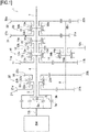
- a dual clutch transmission 1 shown in Fig. 1 is configured to be mounted on a vehicle.
- the dual clutch transmission 1 is controlled functionally by an ECU (whose illustration is omitted) and includes a first clutch 2, a second clutch 3, a first input shaft 4, a second input shaft 5, a counter shaft 6, an output shaft 7, a first splitter gear changing portion 10, a second splitter gear changing portion 20, and an output portion 30.
- the first clutch 2 includes a first pressure plate 2a and a first clutch disc 2b.
- the first pressure plate 2a is fixed to a crankshaft CS of an engine (a power source) EN and rotates together with the crankshaft CS.
- the first clutch disc 2b is fixed to an input end side of the first input shaft 4 and rotates together with the first input shaft 4.
- the first clutch 2 transmits power of the engine EN to the first input shaft 4 when the first pressure plate 2a moves in the direction of the first clutch disc 2b to thereby be brought into press contact with the first clutch disc 2b.
- the second clutch 3 is disposed concentrically with the first clutch 2.
- the second clutch 3 includes a second pressure plate 3a and a second clutch disc 3b.
- the second pressure plate 3a is fixed to the crankshaft CS of the engine EN and rotates together with the crankshaft CS.
- the second clutch disc 3b is fixed to an input end side of the second input shaft 5 and rotates together with the second input shaft 5.
- the second clutch 3 transmits the power of the engine EN to the second input shaft 5 when the second pressure plate 3a moves in the direction of the second clutch disc 3b to thereby be brought into press contact with the second clutch disc 3b.
- the first input shaft 4 is connected to the engine EN via the first clutch 2. This first input shaft 4 rotates as a result of the power of the engine EN being transmitted thereto.
- the second input shaft 5 is a hollow shaft through which the first input shaft 4 is inserted rotatably and is connected to the engine EN via the second clutch 3. This second input shaft 5 rotates in the same direction as the direction in which the first input shaft 4 rotates as a result of the power of the engine EN being transmitted thereto.
- the counter shaft 6 is disposed parallel to the first input shaft 4 and the second input shaft 5.
- the output shaft 7 is disposed parallel to the counter shaft 6 and coaxial with the first input shaft 4 and the second input shaft 5.
- the first splitter gear changing portion 10 includes a first high-speed gear train 11, a first low-speed gear train 12, a first coupling mechanism 13, a second coupling mechanism 14 and a third coupling mechanism 15.
- the first high-speed gear train 11 includes a first input gear 11 a and a first counter gear 11b.
- the first input gear 11a is provided so that the first input shaft 4 can be inserted therethrough rotatably and rotates about the first input shaft 4.
- the first counter gear 11b is fixed to the counter shaft 6 and meshes together with the first input gear 11a. This first counter gear 11b rotates about the counter shaft 6 together with the counter shaft 6 in an opposite direction to a direction in which the first input gear 11 a rotates in association with the rotation of the first input gear 11a.
- the first low-speed gear train 12 includes a second counter gear 12a and an input/output gear 12b.
- the second counter gear 12a is provided so that the counter shaft 6 can be inserted therethrough rotatably and rotates about the counter shaft 6.
- the input/output gear 12b is provided so that the output shaft 7 can be inserted therethrough rotatably and the input/output gear 12b meshes with the second counter gear 12a.
- This input/output gear 12b rotates about the output shaft 7 in an opposite direction to a direction in which the second counter gear 12a rotates in association with the rotation of the second counter gear 12a.
- the first coupling mechanism 13 can couple the first input gear 11 a and the input/output gear 12b selectively to the first input shaft 4.
- the first coupling mechanism 13 includes a coupling hub 13a, a sleeve 13b, and dog gears 13c, 13d.
- the coupling hub 13a is fixed to an output end side of the first input shaft 4 and rotates together with the first input shaft 4.
- the sleeve 13b is provided so as not to rotate but to move axially relative to the coupling hub 13a.
- the dog gear 13c is fixed to the first input gear 11 a and rotates together with the first input gear 11 a.
- the dog gear 13d is fixed to the input/output gear 12b and rotates together with the input/output gear 12b.
- the first coupling mechanism 13 couples the first input gear 11 a to the first input shaft 4 when the sleeve 13b moves in the direction of the dog gear 13c to thereby be brought into engagement with the dog gear 13c. As this occurs, the first input gear 11 a can rotate together with the first input shaft 4. On the other hand, when the sleeve 13b moves in the direction of the dog gear 13d to thereby be brought into engagement with the dog gear 13d, the first coupling mechanism 13 couples the input/output gear 12b to the first input shaft 4. As this occurs, the input/output shaft 12b can rotate together with the first input shaft 4.
- the second coupling mechanism 14 can couple the second counter gear 12a to the counter shaft 6.
- the second coupling mechanism 14 includes a coupling hub 14a, a sleeve 14b, and a dog gear 14c.
- the coupling hub 14a is fixed the counter shaft 6 and rotates together with the counter shaft 6.
- the sleeve 14b is provided so as not to rotate but to move axially relative to the coupling hub 14a.
- the dog gear 14c is fixed to the second counter gear 12a and rotates together with the second counter gear 12a.
- the second coupling mechanism 14 couples the second counter gear 12a to the counter shaft 6 when the sleeve 14b moves in the direction of the dog gear 14c to thereby be brought into engagement with the dog gear 14c. As this occurs, the second counter gear 12a can rotate together with the counter shaft 6.
- the third coupling mechanism 15 can couple the input/output gear 12b to the output shaft 7.
- the third coupling mechanism 15 includes a coupling hub 15a, a sleeve 15b, and a dog gear 15c.
- the coupling hub 15a is fixed to an output shaft 7 and rotates together with the output shaft 7.
- the sleeve 15b is provided so as not to rotate but to move axially relative to the coupling hub 15a.
- the dog gear 15c is fixed to the input/output gear 12b and rotates together with the input/output gear 12b.
- the third coupling mechanism 15 couples the input/output gear 12b to the output shaft 7 when the sleeve 15b moves in the direction of the dog gear 15c to thereby be brought into engagement with the dog gear 15c. As this occurs, the input/output shaft 12b can rotate together with the output shaft 7.
- the second splitter gear changing portion 20 includes a second high-speed gear train 21, a second low-speed gear train 22 and a fourth coupling mechanism 23.
- the second high-speed gear train 21 includes a second input gear 21 a and a third counter gear 21b.
- the second input gear 21a is provided so that the second input shaft 5 can be inserted therethrough rotatably and rotates about the second input shaft 5.
- the third counter gear 21b is fixed to the counter shaft 6 and meshes with the second input gear 21a. This third counter gear 21b rotates about the counter shaft 6 together with the counter shaft 6 in an opposite direction to a direction in which the second input gear 21a rotates in association with the rotation of the second input gear 21a.
- the second low-speed gear train 22 includes a third input gear train 22a and a fourth counter gear 22b.
- the third input gear 22a is provided so that the first input shaft 4 can be inserted rotatably and rotates about the first input shaft 4.
- the fourth counter gear 22b is fixed to the counter shaft 6 and meshes with the third input gear 22a. This fourth counter gear 22b rotates about the counter shaft 6 together with the counter shaft 6 in an opposite direction to a direction in which the third input gear 22a rotates in association with the rotation of the third input gear 22a.
- the fourth coupling mechanism 23 can couple the second input gear 21 a and the third input gear 22a selectively to the second input shaft 5.
- the fourth coupling mechanism 23 includes a coupling hub 23a, a sleeve 23b, and dog gears 23c, 23d.
- the coupling hub 23a is fixed to an output end side of the second input shaft 5 and rotates together with the second input shaft 5.
- the sleeve 23b is provided so as not to rotate but to move axially relative to the coupling hub 23a.
- the dog gear 23c is fixed to the second input gear 21a and rotates together with the second input gear 21a.
- the dog gear 23d is fixed to the third input gear 22a and rotates together with the third input gear 22a.
- the fourth coupling mechanism 23 couples the second input gear 21 a to the second input shaft 5 when the sleeve 23b moves in the direction of the dog gear 23c to thereby be brought into engagement with the dog gear 23c. As this occurs, the second input gear 21a can rotate together with the second input shaft 5.
- the fourth coupling mechanism 23 couples the third input gear 22a to the second input shaft 5 when the sleeve 23b moves in the direction of the dog gear 23d to thereby be brought into engagement with the dog gear 23d. As this occurs, the third input gear 22a can rotate together with the second input shaft 5.
- the output portion 30 includes a forward gear train 31, a reverse gear train 32 and a fifth coupling mechanism 33.
- the forward gear train 31 includes a fifth counter gear 31 a and a forward output gear 31b.
- the fifth counter gear 31a is fixed to the counter shaft 6.
- the fifth counter gear 31a rotates about the counter shaft 6 together with the counter shaft 6.
- the forward output gear 31b is provided so that the output shaft 7 is inserted therethrough rotatably and the forward output gear 31b meshes with the fifth counter gear 31a.
- This forward output gear 31b rotates about the output shaft 7 in an opposite direction to a direction in which the fifth counter gear 31a rotates in association with the rotation of the fifth counter gear 31 a.
- the reverse gear train 32 includes a sixth counter gear 32a, an idler gear 32b and a reverse output gear 32c.
- the sixth counter gear 32a is fixed to the counter shaft 6.
- the sixth counter gear 32a rotates about the counter shaft 6 together with the counter shaft 6.
- the idler gear 32b is provided so as not only to be attached to a shaft (whose illustration is omitted) parallel to the counter shaft 6 but also to mesh with the sixth counter gear 32a.
- This idler gear 32b rotates in an opposite direction to a direction in which the sixth counter gear 32a rotates in association with the rotation of the sixth counter gear 32a.
- the reverse output gear 32c is provided so that the output shaft 7 is inserted therethrough rotatably and the reverse output gear 32c meshes with the idler gear 32b.
- the reverse output gear 32c rotates about the output shaft 7 in an opposite direction to a direction in which the idler gear 32b rotates and in the same direction as a direction in which the sixth counter gear 32a rotates in association with the rotation of the idler gear 32b.
- a relationship among the sixth counter gear 32a, the idler gear 32b and the reverse output gear 32c in the drawings is drawn according to the related-art practice and differs from a relationship in reality.
- the fifth coupling mechanism 33 can couple the forward output gear 31b and the reverse output gear 32c selectively to the output shaft 7.
- the fifth coupling mechanism 33 includes a coupling hub 33a, a sleeve 33b, and dog gears 33c, 33d.
- the coupling hub 33a is fixed to an output shaft 7 and rotates together with the output shaft 7.
- the sleeve 33b is provided so as not to rotate but to move axially relative to the coupling hub 33a.
- the dog gear 33c is fixed to the forward output gear 31b and rotates together with the forward output gear 31b.
- the dog gear 33d is fixed to the reverse output gear 32c and rotates together with the reverse output gear 32c.
- the fifth coupling mechanism 33 couples the forward output gear 31b to the output shaft 7 when the sleeve 33b moves in the direction of the dog gear 33c to thereby be brought into engagement with the dog gear 33c. As this occurs, the forward output gear 31b can rotate together with the output shaft 7.
- the fifth coupling mechanism 33 couples the reverse output gear 32c to the output shaft 7 when the sleeve 33b moves in the direction of the dog gear 33d to thereby be brought into engagement with the dog gear 33d. As this occurs, the reverse output gear 32c can rotate together with the output shaft 7.
- the input/output gear 12b is coupled to the first input shaft 4 by the first coupling mechanism 13
- the input/output gear 12b is coupled to the output shaft 7 by the third coupling mechanism 15, and the first clutch 2 is applied.
- the power of the engine EN is transmitted sequentially from the first clutch 2 to the first input shaft 4, the input/output gear 12b and the output shaft 7 in that order.
- the first input gear 11a is coupled to the first input shaft 4 by the first coupling mechanism 13
- the second counter gear 12a is coupled to the counter shaft 6 by the second coupling mechanism 14
- the input/output gear 12b is coupled to the output shaft 7 by the third coupling mechanism 15, and the first clutch 2 is applied.
- the power of the engine EN is transmitted sequentially from the first clutch 2 to the first input shaft 4, the first high-speed gear train 11, the counter shaft 6, the first low-speed gear train 12, and the output shaft 7 in that order.
- the second input gear 21a is coupled to the second input shaft 5 by the fourth coupling mechanism 23
- the second counter gear 12a is coupled to the counter shaft 6 by the second coupling mechanism 14
- the output gear 12b is coupled to the output shaft 7 by the third coupling mechanism 15, and the second clutch 3 is applied.
- the power of the engine EN is transmitted sequentially from the second clutch 3 to the second input shaft 5, the second high-speed gear train 21, the counter shaft 6, the first low-speed gear train 12, and the output shaft 7 in that order.
- the first input gear, 11 a, the input/output gear 12b, the second input gear 21a, and the third input gear 22a can be connected alternately to the first input shaft 4 or the second input shaft 5 in such a way as to replace the gear which is then connected to the first input shaft 4 or the second input shaft 5, and the forward output gear 31b can be coupled to the output shaft 7 as required.
- four speed gears to be changed are realized on a low speed side.
- first input gear 11 a, the second input gear 21a and the third input gear 22a are connected alternately to the first input shaft 4 or the second input shaft 5 in such a way as to replace the gear which is then connected to the first input shaft 4 or the second input shaft 5, and the input/output gear 12b is coupled to the output shaft 7 as required.
- the four speed gears to be changed can be realized on the high-speed side, including the time when the fifth gear is engaged in which the first input shaft 4 is connected directly to the output shaft 7.
- a dual clutch transmission 100 according to the comparison example is such that the first counter gear and the second counter bear of the dual-transmission 1 of the first embodiment is integrated into one unit.
- Like reference numerals will be given to like configurations to those of the first embodiment, and the description thereof will be omitted below.
- the dual clutch transmission 100 shown in Fig. 10 includes a first counter gear 11c and a second counter gear 12c, and a second coupling mechanism 16.
- the first counter gear 11c and the second counter gear 12c are integrated into one unit.
- the first counter gear 11c is provided so that a counter shaft 6 is inserted therethrough rotatably and the first counter gear 11c meshes with a first input gear 11 a.
- the second counter gear 12c is provided so that the counter shaft 6 is inserted therethrough rotatably and the second counter gear 12c meshes with an input/output gear 12b.
- the first counter gear 11c and the second counter gear 12c rotate about the counter shaft 6 in an opposite direction to a direction in which the first input gear 11 a and the input/output gear 12b rotate in association with the rotation of the first input gear 11 a and the input/output gear 12b.
- the second coupling mechanism 16 can couple the first counter gear 11c and the second counter gear 12c which are integrated into one unit to the counter shaft 6.
- the second coupling mechanism 16 includes a coupling hub 16a, a sleeve 16b, and a dog gear 16c.
- the coupling hub 16a is fixed the counter shaft 6 and rotates together with the counter shaft 6.
- the sleeve 16b is provided so as not to rotate but to move axially relative to the coupling hub 16a.
- the dog gear 16c is fixed to the first counter gear 11c and the second counter gear 12c which are integrated into one unit and rotates together with the first counter gear 11c and the second counter gear 12c.
- the second coupling mechanism 16 couples the first counter gear 11c and the second counter gear 12c to the counter shaft 6 when the sleeve 16b moves in the direction of the dog gear 16c to thereby be brought into engagement with the dog gear 16c. As this occurs, the first counter gear 11c and the second counter gear 12c can rotate together with the counter shaft 6.
- the comparison example it is possible to increase the number of gears to be changed without increasing the number of gears.
- the first counter gear 11c and the second counter gear 12c are integrated into one unit, there may be a situation in which a differential rotation is caused while transmitting the power of the engine EN.
- the first counter gear 11b and the second counter gear 12a are formed independent of each other, there is no such situation in which a differential rotation is caused while transmitting the power of the engine EN.
Landscapes
- Engineering & Computer Science (AREA)
- General Engineering & Computer Science (AREA)
- Mechanical Engineering (AREA)
- Structure Of Transmissions (AREA)
Abstract
Description
- The present invention relates to a dual clutch transmission configured to be mounted on a vehicle.
- There have been known dual clutch transmissions having two clutches (for example, refer to PTL 1). A dual clutch transmission, which is a power transmission mechanism, has two systems of odd-numbered gears and even-numbered gears which correspond individually to two clutches thereof and changes the gears by engaging the two systems in an alternate fashion. With such a dual clutch transmission, since while one system is engaged, the other system is waiting, a gear change requires a short period of time.
- PTL 1:
JP-T-2010-531417 - However, in order to increase the number of gears to be changed in such a related-art structure, the number of gears needs to be increased, which calls for the increase in overall size, weight and cost of a transmission to be produced.
- Then, an object of the invention is to provide a dual clutch transmission in which the number of gears to be changed is increased while suppressing the increase in size, weight and cost thereof.
- With a view to achieving the object, according to the invention, there is provided a dual clutch transmission mounted on a vehicle which includes a first clutch, a second clutch, a first input shaft, a second input shaft, a counter shaft, an output shaft, a first splitter gear changing portion, a second splitter gear changing portion, and an output portion.
- The second clutch is disposed concentrically with the first clutch. The first input shaft is connected to a power source via the first clutch. The second input shaft is a hollow shaft through which the first input shaft is inserted rotatably and is connected to the power source via the second clutch. The counter shaft is disposed parallel to the first input shaft and the second input shaft. The output shaft is disposed parallel to the counter shaft and coaxial with the first input shaft and the second input shaft.
- The first splitter gear changing portion has a first input gear through which the first input shaft is inserted rotatably, a first counter gear which is fixed to the counter shaft and which meshes with the first input gear, a second counter gear through which the counter shaft is inserted rotatably, an input/output gear through which the output gear is inserted rotatably and which meshes with the second counter gear, a first coupling mechanism configured to couple the first input gear and the input/output gear selectively to the first input shaft, a second coupling mechanism configured to couple the second counter gear to the counter shaft, and a third coupling mechanism configured to couple the input/output gear to the output shaft.
- The splitter gear changing portion has a second input gear through which the second input shaft is inserted rotatably, a third counter gear which is fixed to the counter shaft and which meshes with the second input gear, a third input gear through which the first input shaft is inserted rotatably, a fourth counter gear which is fixed to the counter shaft and which meshes with the third input gear, and a fourth coupling mechanism configured to couple the second input gear and the third input gear selectively to the second input shaft.
- The output portion has a fifth counter gear which is fixed to the counter shaft, an output gear through which the output shaft is inserted rotatably and which meshes with the fifth counter gear, and a fifth coupling mechanism configured to couple the output gear to the output shaft.
- In the configuration described above, the first input gear, the input/output gear, the second input gear and the third input gear are connected alternately to the first input shaft or the second input shaft in such a way as to replace the gear which is then connected to the first input shaft or the second input shaft, and the output gear is coupled to the output shaft as required. By doing so, four speed gears to be changed are realized on a low speed side.
- In addition, the first input gear, the second input gear and the third input gear are connected alternately to the first input shaft or the second input shaft in such a way as to replace the gear which is then connected to the first input shaft or the second input shaft, and the input/output gear is coupled to the output shaft as required. By doing so, four speed gears to be changed are realized on a high speed side, including a fifth speed gear where the first input shaft is coupled directly to the output shaft.
- Consequently, it is possible to increase the number of gears to be changed without increasing the number of gears.
- According to the dual clutch transmission of the invention, it is possible to increase the number of gears to be changed while suppressing the increase in size, weight and cost thereof.
-
- [
Fig. 1] Fig. 1 is a schematic diagram showing a dual clutch transmission according to a first embodiment of the invention. - [
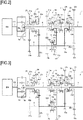
Fig. 2] Fig. 2 is a diagram showing a power transmission path when a first gear is engaged in the dual clutch transmission shown inFig. 1 . - [
Fig. 3] Fig. 3 is a diagram showing a power transmission path when a second gear is engaged in the dual clutch transmission shown inFig. 1 . - [
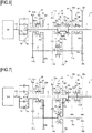
Fig. 4] Fig. 4 is a diagram showing a power transmission path when a third gear is engaged in the dual clutch transmission shown inFig. 1 . - [
Fig. 5] Fig. 5 is a diagram showing a power transmission path when a fourth gear is engaged in the dual clutch transmission shown inFig. 1 . - [
Fig. 6] Fig. 6 is a diagram showing a power transmission path when a fifth gear is engaged in the dual clutch transmission shown inFig. 1 . - [
Fig. 7] Fig. 7 is a diagram showing a power transmission path when a sixth gear is engaged in the dual clutch transmission shown inFig. 1 . - [
Fig. 8] Fig. 8 is a diagram showing a power transmission path when a seventh gear is engaged in the dual clutch transmission shown inFig. 1 . - [
Fig. 9] Fig. 9 is a diagram showing a power transmission path when an eighth gear is engaged in the dual clutch transmission shown inFig. 1 . - [
Fig. 10] Fig. 10 is a schematic diagram showing a dual clutch transmission according to a comparison example. - Hereinafter, an embodiment of the invention will be described in detail by reference to the drawings.
- A dual clutch transmission 1 shown in
Fig. 1 is configured to be mounted on a vehicle. Specifically, the dual clutch transmission 1 is controlled functionally by an ECU (whose illustration is omitted) and includes afirst clutch 2, asecond clutch 3, afirst input shaft 4, a second input shaft 5, a counter shaft 6, anoutput shaft 7, a first splittergear changing portion 10, a second splittergear changing portion 20, and anoutput portion 30. - The
first clutch 2 includes afirst pressure plate 2a and afirst clutch disc 2b. Thefirst pressure plate 2a is fixed to a crankshaft CS of an engine (a power source) EN and rotates together with the crankshaft CS. Thefirst clutch disc 2b is fixed to an input end side of thefirst input shaft 4 and rotates together with thefirst input shaft 4. Thefirst clutch 2 transmits power of the engine EN to thefirst input shaft 4 when thefirst pressure plate 2a moves in the direction of thefirst clutch disc 2b to thereby be brought into press contact with thefirst clutch disc 2b. - The
second clutch 3 is disposed concentrically with thefirst clutch 2. Specifically, thesecond clutch 3 includes asecond pressure plate 3a and asecond clutch disc 3b. Thesecond pressure plate 3a is fixed to the crankshaft CS of the engine EN and rotates together with the crankshaft CS. Thesecond clutch disc 3b is fixed to an input end side of the second input shaft 5 and rotates together with the second input shaft 5. Thesecond clutch 3 transmits the power of the engine EN to the second input shaft 5 when thesecond pressure plate 3a moves in the direction of thesecond clutch disc 3b to thereby be brought into press contact with thesecond clutch disc 3b. - The
first input shaft 4 is connected to the engine EN via thefirst clutch 2. Thisfirst input shaft 4 rotates as a result of the power of the engine EN being transmitted thereto. - The second input shaft 5 is a hollow shaft through which the
first input shaft 4 is inserted rotatably and is connected to the engine EN via thesecond clutch 3. This second input shaft 5 rotates in the same direction as the direction in which thefirst input shaft 4 rotates as a result of the power of the engine EN being transmitted thereto. - The counter shaft 6 is disposed parallel to the
first input shaft 4 and the second input shaft 5. - The
output shaft 7 is disposed parallel to the counter shaft 6 and coaxial with thefirst input shaft 4 and the second input shaft 5. - The first splitter
gear changing portion 10 includes a first high-speed gear train 11, a first low-speed gear train 12, afirst coupling mechanism 13, asecond coupling mechanism 14 and athird coupling mechanism 15. - The first high-
speed gear train 11 includes afirst input gear 11 a and afirst counter gear 11b. Thefirst input gear 11a is provided so that thefirst input shaft 4 can be inserted therethrough rotatably and rotates about thefirst input shaft 4. Thefirst counter gear 11b is fixed to the counter shaft 6 and meshes together with thefirst input gear 11a. Thisfirst counter gear 11b rotates about the counter shaft 6 together with the counter shaft 6 in an opposite direction to a direction in which thefirst input gear 11 a rotates in association with the rotation of thefirst input gear 11a. - The first low-
speed gear train 12 includes asecond counter gear 12a and an input/output gear 12b. Thesecond counter gear 12a is provided so that the counter shaft 6 can be inserted therethrough rotatably and rotates about the counter shaft 6. The input/output gear 12b is provided so that theoutput shaft 7 can be inserted therethrough rotatably and the input/output gear 12b meshes with thesecond counter gear 12a. This input/output gear 12b rotates about theoutput shaft 7 in an opposite direction to a direction in which thesecond counter gear 12a rotates in association with the rotation of thesecond counter gear 12a. - The
first coupling mechanism 13 can couple thefirst input gear 11 a and the input/output gear 12b selectively to thefirst input shaft 4. Specifically, thefirst coupling mechanism 13 includes acoupling hub 13a, asleeve 13b, and dog gears 13c, 13d. Thecoupling hub 13a is fixed to an output end side of thefirst input shaft 4 and rotates together with thefirst input shaft 4. Thesleeve 13b is provided so as not to rotate but to move axially relative to thecoupling hub 13a. Thedog gear 13c is fixed to thefirst input gear 11 a and rotates together with thefirst input gear 11 a. Thedog gear 13d is fixed to the input/output gear 12b and rotates together with the input/output gear 12b. - The
first coupling mechanism 13 couples thefirst input gear 11 a to thefirst input shaft 4 when thesleeve 13b moves in the direction of thedog gear 13c to thereby be brought into engagement with thedog gear 13c. As this occurs, thefirst input gear 11 a can rotate together with thefirst input shaft 4. On the other hand, when thesleeve 13b moves in the direction of thedog gear 13d to thereby be brought into engagement with thedog gear 13d, thefirst coupling mechanism 13 couples the input/output gear 12b to thefirst input shaft 4. As this occurs, the input/output shaft 12b can rotate together with thefirst input shaft 4. - The
second coupling mechanism 14 can couple thesecond counter gear 12a to the counter shaft 6. Specifically, thesecond coupling mechanism 14 includes acoupling hub 14a, asleeve 14b, and adog gear 14c. Thecoupling hub 14a is fixed the counter shaft 6 and rotates together with the counter shaft 6. Thesleeve 14b is provided so as not to rotate but to move axially relative to thecoupling hub 14a. Thedog gear 14c is fixed to thesecond counter gear 12a and rotates together with thesecond counter gear 12a. - The
second coupling mechanism 14 couples thesecond counter gear 12a to the counter shaft 6 when thesleeve 14b moves in the direction of thedog gear 14c to thereby be brought into engagement with thedog gear 14c. As this occurs, thesecond counter gear 12a can rotate together with the counter shaft 6. - The
third coupling mechanism 15 can couple the input/output gear 12b to theoutput shaft 7. Specifically, thethird coupling mechanism 15 includes acoupling hub 15a, asleeve 15b, and adog gear 15c. Thecoupling hub 15a is fixed to anoutput shaft 7 and rotates together with theoutput shaft 7. Thesleeve 15b is provided so as not to rotate but to move axially relative to thecoupling hub 15a. Thedog gear 15c is fixed to the input/output gear 12b and rotates together with the input/output gear 12b. - The
third coupling mechanism 15 couples the input/output gear 12b to theoutput shaft 7 when thesleeve 15b moves in the direction of thedog gear 15c to thereby be brought into engagement with thedog gear 15c. As this occurs, the input/output shaft 12b can rotate together with theoutput shaft 7. - The second splitter
gear changing portion 20 includes a second high-speed gear train 21, a second low-speed gear train 22 and afourth coupling mechanism 23. - The second high-
speed gear train 21 includes asecond input gear 21 a and athird counter gear 21b. Thesecond input gear 21a is provided so that the second input shaft 5 can be inserted therethrough rotatably and rotates about the second input shaft 5. Thethird counter gear 21b is fixed to the counter shaft 6 and meshes with thesecond input gear 21a. Thisthird counter gear 21b rotates about the counter shaft 6 together with the counter shaft 6 in an opposite direction to a direction in which thesecond input gear 21a rotates in association with the rotation of thesecond input gear 21a. - The second low-
speed gear train 22 includes a thirdinput gear train 22a and afourth counter gear 22b. Thethird input gear 22a is provided so that thefirst input shaft 4 can be inserted rotatably and rotates about thefirst input shaft 4. Thefourth counter gear 22b is fixed to the counter shaft 6 and meshes with thethird input gear 22a. Thisfourth counter gear 22b rotates about the counter shaft 6 together with the counter shaft 6 in an opposite direction to a direction in which thethird input gear 22a rotates in association with the rotation of thethird input gear 22a. - The
fourth coupling mechanism 23 can couple thesecond input gear 21 a and thethird input gear 22a selectively to the second input shaft 5. Specifically, thefourth coupling mechanism 23 includes acoupling hub 23a, asleeve 23b, and dog gears 23c, 23d. Thecoupling hub 23a is fixed to an output end side of the second input shaft 5 and rotates together with the second input shaft 5. Thesleeve 23b is provided so as not to rotate but to move axially relative to thecoupling hub 23a. Thedog gear 23c is fixed to thesecond input gear 21a and rotates together with thesecond input gear 21a. Thedog gear 23d is fixed to thethird input gear 22a and rotates together with thethird input gear 22a. - The
fourth coupling mechanism 23 couples thesecond input gear 21 a to the second input shaft 5 when thesleeve 23b moves in the direction of thedog gear 23c to thereby be brought into engagement with thedog gear 23c. As this occurs, thesecond input gear 21a can rotate together with the second input shaft 5. On the other hand, thefourth coupling mechanism 23 couples thethird input gear 22a to the second input shaft 5 when thesleeve 23b moves in the direction of thedog gear 23d to thereby be brought into engagement with thedog gear 23d. As this occurs, thethird input gear 22a can rotate together with the second input shaft 5. - The
output portion 30 includes aforward gear train 31, areverse gear train 32 and afifth coupling mechanism 33. - The
forward gear train 31 includes afifth counter gear 31 a and aforward output gear 31b. Thefifth counter gear 31a is fixed to the counter shaft 6. Thefifth counter gear 31a rotates about the counter shaft 6 together with the counter shaft 6. Theforward output gear 31b is provided so that theoutput shaft 7 is inserted therethrough rotatably and theforward output gear 31b meshes with thefifth counter gear 31a. Thisforward output gear 31b rotates about theoutput shaft 7 in an opposite direction to a direction in which thefifth counter gear 31a rotates in association with the rotation of thefifth counter gear 31 a. - The
reverse gear train 32 includes asixth counter gear 32a, anidler gear 32b and areverse output gear 32c. Thesixth counter gear 32a is fixed to the counter shaft 6. Thesixth counter gear 32a rotates about the counter shaft 6 together with the counter shaft 6. Theidler gear 32b is provided so as not only to be attached to a shaft (whose illustration is omitted) parallel to the counter shaft 6 but also to mesh with thesixth counter gear 32a. Thisidler gear 32b rotates in an opposite direction to a direction in which thesixth counter gear 32a rotates in association with the rotation of thesixth counter gear 32a. Thereverse output gear 32c is provided so that theoutput shaft 7 is inserted therethrough rotatably and thereverse output gear 32c meshes with theidler gear 32b. Thereverse output gear 32c rotates about theoutput shaft 7 in an opposite direction to a direction in which theidler gear 32b rotates and in the same direction as a direction in which thesixth counter gear 32a rotates in association with the rotation of theidler gear 32b. A relationship among thesixth counter gear 32a, theidler gear 32b and thereverse output gear 32c in the drawings is drawn according to the related-art practice and differs from a relationship in reality. - The
fifth coupling mechanism 33 can couple theforward output gear 31b and thereverse output gear 32c selectively to theoutput shaft 7. Specifically, thefifth coupling mechanism 33 includes acoupling hub 33a, asleeve 33b, and dog gears 33c, 33d. Thecoupling hub 33a is fixed to anoutput shaft 7 and rotates together with theoutput shaft 7. Thesleeve 33b is provided so as not to rotate but to move axially relative to thecoupling hub 33a. Thedog gear 33c is fixed to theforward output gear 31b and rotates together with theforward output gear 31b. Thedog gear 33d is fixed to thereverse output gear 32c and rotates together with thereverse output gear 32c. - The
fifth coupling mechanism 33 couples theforward output gear 31b to theoutput shaft 7 when thesleeve 33b moves in the direction of thedog gear 33c to thereby be brought into engagement with thedog gear 33c. As this occurs, theforward output gear 31b can rotate together with theoutput shaft 7. On the other hand, thefifth coupling mechanism 33 couples thereverse output gear 32c to theoutput shaft 7 when thesleeve 33b moves in the direction of thedog gear 33d to thereby be brought into engagement with thedog gear 33d. As this occurs, thereverse output gear 32c can rotate together with theoutput shaft 7. - Next, power transmission paths of the dual clutch transmission 1 will be described.
- When a first gear is engaged as shown in
Fig. 2 , in the dual clutch transmission 1, the input/output gear 12b is coupled to thefirst input shaft 4 by thefirst coupling mechanism 13, thesecond counter gear 12a is coupled to the counter shaft 6 by thesecond coupling mechanism 14, theforward output gear 31b is coupled to theoutput shaft 7 by thefifth coupling mechanism 33, and thefirst clutch 2 is applied. By doing so, the power of the engine EN is transmitted sequentially from thefirst clutch 2 to thefirst input shaft 4, the first low-speed gear train 12, the counter shaft 6, theforward gear train 31 and theoutput shaft 7 in that order. - When a second gear is engaged as shown in
Fig. 3 , in the dual clutch transmission 1, thethird input gear 22a is coupled to the second input shaft 5 by thefourth coupling mechanism 23, theforward output gear 31b is coupled to theoutput shaft 7 by thefifth coupling mechanism 33, and thesecond clutch 3 is applied. By doing so, the power of the engine EN is transmitted sequentially from thesecond clutch 3 to the second input shaft 5, the second low-speed gear train 22, the counter shaft 6, theforward gear train 31 and theoutput shaft 7 in that order. - When a third gear is engaged as shown in
Fig. 4 , in the dual clutch transmission 1, thefirst input gear 11a is coupled to thefirst input shaft 4 by thefirst coupling mechanism 13, theforward output gear 31b is coupled to theoutput shaft 7 by thefifth coupling mechanism 33, and thefirst clutch 2 is applied. By doing so, the power of the engine EN is transmitted sequentially from thefirst clutch 2 to thefirst input shaft 4, the first high-speed gear train 11, the counter shaft 6, theforward gear train 31 and theoutput shaft 7 in that order. - When a fourth gear is engaged as shown in
Fig. 5 , in the dual clutch transmission 1, thesecond input gear 21a is coupled to the second input shaft 5 by thefourth coupling mechanism 23, theforward output gear 31b is coupled to theoutput shaft 7 by thefifth coupling mechanism 33, and thesecond clutch 3 is applied. By doing so, the power of the engine EN is transmitted sequentially from thesecond clutch 3 to the second input shaft 5, the second high-speed gear train 21, the counter shaft 6, theforward gear train 31 and theoutput shaft 7 in that order. - When a fifth gear is engaged as shown in
Fig. 6 , in the dual clutch transmission 1, the input/output gear 12b is coupled to thefirst input shaft 4 by thefirst coupling mechanism 13, the input/output gear 12b is coupled to theoutput shaft 7 by thethird coupling mechanism 15, and thefirst clutch 2 is applied. By doing so, the power of the engine EN is transmitted sequentially from thefirst clutch 2 to thefirst input shaft 4, the input/output gear 12b and theoutput shaft 7 in that order. - When a sixth gear is engaged as shown in
Fig. 7 , in the dual clutch transmission 1, thethird input gear 22a is coupled to the second input shaft 5 by thefourth coupling mechanism 23, thesecond counter gear 12a is coupled to the counter shaft 6 by thesecond coupling mechanism 14, the input/output gear 12b is coupled to theoutput shaft 7 by thethird coupling mechanism 15, and thesecond clutch 3 is applied. By doing so, the power of the engine EN is transmitted sequentially from thesecond clutch 3 to the second input shaft 5, the second low-speedrear train 22, the counter shaft 6, the first low-speed gear train 12, and theoutput shaft 7 in that order. - When a seventh gear is engaged as shown in
Fig. 8 , in the dual clutch transmission 1, thefirst input gear 11a is coupled to thefirst input shaft 4 by thefirst coupling mechanism 13, thesecond counter gear 12a is coupled to the counter shaft 6 by thesecond coupling mechanism 14, the input/output gear 12b is coupled to theoutput shaft 7 by thethird coupling mechanism 15, and thefirst clutch 2 is applied. By doing so, the power of the engine EN is transmitted sequentially from thefirst clutch 2 to thefirst input shaft 4, the first high-speed gear train 11, the counter shaft 6, the first low-speed gear train 12, and theoutput shaft 7 in that order. - When an eighth gear is engaged as shown in
Fig. 9 , in the dual clutch transmission 1, thesecond input gear 21a is coupled to the second input shaft 5 by thefourth coupling mechanism 23, thesecond counter gear 12a is coupled to the counter shaft 6 by thesecond coupling mechanism 14, theoutput gear 12b is coupled to theoutput shaft 7 by thethird coupling mechanism 15, and thesecond clutch 3 is applied. By doing so, the power of the engine EN is transmitted sequentially from thesecond clutch 3 to the second input shaft 5, the second high-speed gear train 21, the counter shaft 6, the first low-speed gear train 12, and theoutput shaft 7 in that order. - According to this embodiment, the first input gear, 11 a, the input/
output gear 12b, thesecond input gear 21a, and thethird input gear 22a can be connected alternately to thefirst input shaft 4 or the second input shaft 5 in such a way as to replace the gear which is then connected to thefirst input shaft 4 or the second input shaft 5, and theforward output gear 31b can be coupled to theoutput shaft 7 as required. By doing so, four speed gears to be changed are realized on a low speed side. - In addition, the
first input gear 11 a, thesecond input gear 21a and thethird input gear 22a are connected alternately to thefirst input shaft 4 or the second input shaft 5 in such a way as to replace the gear which is then connected to thefirst input shaft 4 or the second input shaft 5, and the input/output gear 12b is coupled to theoutput shaft 7 as required. By doing so, the four speed gears to be changed can be realized on the high-speed side, including the time when the fifth gear is engaged in which thefirst input shaft 4 is connected directly to theoutput shaft 7. - Consequently, it is possible to increase the number of gears to be changed without increasing the number of gears.
- Next, a comparison example will be described by reference to the drawings. A dual
clutch transmission 100 according to the comparison example is such that the first counter gear and the second counter bear of the dual-transmission 1 of the first embodiment is integrated into one unit. Like reference numerals will be given to like configurations to those of the first embodiment, and the description thereof will be omitted below. - The dual
clutch transmission 100 shown inFig. 10 includes afirst counter gear 11c and asecond counter gear 12c, and a second coupling mechanism 16. - The
first counter gear 11c and thesecond counter gear 12c are integrated into one unit. Thefirst counter gear 11c is provided so that a counter shaft 6 is inserted therethrough rotatably and thefirst counter gear 11c meshes with afirst input gear 11 a. Thesecond counter gear 12c is provided so that the counter shaft 6 is inserted therethrough rotatably and thesecond counter gear 12c meshes with an input/output gear 12b. Thefirst counter gear 11c and thesecond counter gear 12c rotate about the counter shaft 6 in an opposite direction to a direction in which thefirst input gear 11 a and the input/output gear 12b rotate in association with the rotation of thefirst input gear 11 a and the input/output gear 12b. - The second coupling mechanism 16 can couple the
first counter gear 11c and thesecond counter gear 12c which are integrated into one unit to the counter shaft 6. Specifically, the second coupling mechanism 16 includes acoupling hub 16a, asleeve 16b, and adog gear 16c. Thecoupling hub 16a is fixed the counter shaft 6 and rotates together with the counter shaft 6. Thesleeve 16b is provided so as not to rotate but to move axially relative to thecoupling hub 16a. Thedog gear 16c is fixed to thefirst counter gear 11c and thesecond counter gear 12c which are integrated into one unit and rotates together with thefirst counter gear 11c and thesecond counter gear 12c. - The second coupling mechanism 16 couples the
first counter gear 11c and thesecond counter gear 12c to the counter shaft 6 when thesleeve 16b moves in the direction of thedog gear 16c to thereby be brought into engagement with thedog gear 16c. As this occurs, thefirst counter gear 11c and thesecond counter gear 12c can rotate together with the counter shaft 6. - According to the comparison example, it is possible to increase the number of gears to be changed without increasing the number of gears. However, since the
first counter gear 11c and thesecond counter gear 12c are integrated into one unit, there may be a situation in which a differential rotation is caused while transmitting the power of the engine EN. On the other hand, according to the embodiment, since thefirst counter gear 11b and thesecond counter gear 12a are formed independent of each other, there is no such situation in which a differential rotation is caused while transmitting the power of the engine EN. - Thus, while the embodiments to which the invention made by the inventor is applied have been described heretofore, the invention is not limited at all by the description and the drawings which make up part of the disclosure of the invention based on the embodiments. Namely, other embodiments, examples and operating techniques which are made based on the embodiments described herein by those skilled in the art to which the invention pertains should all, of course, be included in the scope of the invention.
-
- 1
- dual clutch transmission
- 2
- first clutch
- 3
- second clutch
- 4
- first input shaft
- 5
- second input shaft
- 6
- counter shaft
- 7
- output shaft
- 10
- first splitter gear changing portion
- 11a
- first input gear
- 11b
- first counter gear
- 12a
- second counter gear
- 12b
- input/output gear
- 13
- first coupling mechanism
- 14
- second coupling mechanism
- 15
- third coupling mechanism
- 20
- second splitter gear changing portion
- 21a
- second input gear
- 21b
- third counter gear
- 22a
- third input gear
- 22b
- fourth counter gear
- 23
- fourth coupling mechanism
- 30
- output portion
- 31a
- fifth counter gear
- 31b
- forward output gear (output gear)
- 33
- fifth coupling mechanism
- EN
- engine (power source)
Claims (1)
- A dual clutch transmission comprising:a first clutch;a second clutch that is disposed concentrically with the first clutch;a first input shaft that is connected to a power source via the first clutch;a second input shaft that is a hollow shaft through which the input shaft is inserted rotatably, the second input shaft being connected to the power source via the second clutch;a counter shaft that is disposed parallel to the first input shaft and the second input shaft;an output shaft that is disposed parallel to the counter shaft and coaxial with the first input shaft and the second input shaft;a first splitter gear changing portion comprising:a first input gear through which the first input shaft is inserted rotatably;a first counter gear that is fixed to the counter shaft and meshes with the first input gear;a second counter gear through which the counter shaft is inserted rotatably;an input/output gear through which the output shaft is inserted rotatably, the input/output gear meshing with the second counter gear;a first coupling mechanism configured to couple the first input gear and the input/output gear selectively to the first input shaft;a second coupling mechanism configured to couple the second counter gear to the counter shaft; anda third coupling mechanism configured to couple the input/output gear to the output shaft;a second splitter gear changing portion comprising:a second input gear through which the second input shaft is inserted rotatably;a third counter gear that is fixed to the counter shaft and meshes with the second input gear;a third input gear through which the first input shaft is inserted rotatably;a fourth counter gear that is fixed to the counter shaft and meshes with the third input gear; anda fourth coupling mechanism configured to couple the second input gear and the third input gear selectively to the second input shaft; andan output portion comprising:a fifth counter gear that is fixed to the counter shaft;an output gear through which the output shaft is inserted rotatably, the output gear meshing with the fifth counter gear; anda fifth coupling mechanism configured to couple the output gear to the output shaft.
Applications Claiming Priority (2)
| Application Number | Priority Date | Filing Date | Title |
|---|---|---|---|
| JP2014178719A JP2016053378A (en) | 2014-09-03 | 2014-09-03 | Dual clutch transmission |
| PCT/JP2015/075053 WO2016035848A1 (en) | 2014-09-03 | 2015-09-03 | Dual clutch transmission |
Publications (2)
| Publication Number | Publication Date |
|---|---|
| EP3190312A1 true EP3190312A1 (en) | 2017-07-12 |
| EP3190312A4 EP3190312A4 (en) | 2018-05-16 |
Family
ID=55439905
Family Applications (1)
| Application Number | Title | Priority Date | Filing Date |
|---|---|---|---|
| EP15838587.2A Withdrawn EP3190312A4 (en) | 2014-09-03 | 2015-09-03 | Dual clutch transmission |
Country Status (5)
| Country | Link |
|---|---|
| US (1) | US10100904B2 (en) |
| EP (1) | EP3190312A4 (en) |
| JP (1) | JP2016053378A (en) |
| CN (1) | CN107076270B (en) |
| WO (1) | WO2016035848A1 (en) |
Families Citing this family (1)
| Publication number | Priority date | Publication date | Assignee | Title |
|---|---|---|---|---|
| JP6759781B2 (en) * | 2016-07-11 | 2020-09-23 | いすゞ自動車株式会社 | Dual clutch transmission |
Family Cites Families (19)
| Publication number | Priority date | Publication date | Assignee | Title |
|---|---|---|---|---|
| JP2956364B2 (en) * | 1992-07-02 | 1999-10-04 | トヨタ自動車株式会社 | Manual gear transmission |
| DE59803989D1 (en) * | 1998-11-27 | 2002-06-06 | Ford Global Tech Inc | Gearbox with a countershaft, especially for motor vehicles |
| DE10165097B3 (en) | 2000-07-18 | 2015-07-23 | Schaeffler Technologies AG & Co. KG | Double clutch |
| DE10037398A1 (en) * | 2000-08-01 | 2002-02-14 | Daimler Chrysler Ag | Gearbox with parallel clutches in load train provides fourth and fifth speeds sharing common clutch, with optional sixth speed |
| KR100634589B1 (en) * | 2003-12-24 | 2006-10-13 | 현대자동차주식회사 | Dual clutch transmission for hybrid electric vehicle and its operation method by mode |
| US7082850B2 (en) * | 2003-12-30 | 2006-08-01 | Eaton Corporation | Hybrid powertrain system |
| DE102005005338B3 (en) * | 2005-01-27 | 2006-08-10 | Getrag Getriebe- Und Zahnradfabrik Hermann Hagenmeyer Gmbh & Cie Kg | Speed gearbox |
| DE102005058946A1 (en) * | 2005-12-09 | 2007-07-05 | Zf Friedrichshafen Ag | Bearing of the gear shafts of a dual-clutch gearbox |
| DE102006015661A1 (en) * | 2006-04-04 | 2007-10-11 | Daimlerchrysler Ag | Powershift transmission for a commercial vehicle |
| JP4274210B2 (en) * | 2006-08-08 | 2009-06-03 | いすゞ自動車株式会社 | Output shaft reduction type dual clutch transmission |
| DE102006054281A1 (en) * | 2006-11-17 | 2008-06-12 | Zf Friedrichshafen Ag | Double clutch winding transmission |
| DE102007029634A1 (en) | 2007-06-26 | 2009-01-08 | Daimler Ag | Gear shift transmission |
| DE102009014357A1 (en) * | 2009-03-21 | 2010-09-23 | Daimler Ag | Double clutch transmission has gear level which is formed in three transmission gears as output gear level, and clutch unit is provided to switch gear level as input gear level |
| DE102012203058A1 (en) * | 2012-02-29 | 2013-08-29 | Zf Friedrichshafen Ag | Gearbox, particularly dual clutch gearbox for motor vehicle, has three or multiple switching devices, where one of switching devices is arranged on minor axis, while two of switching devices are arranged on main axis |
| DE102013113908A1 (en) | 2012-12-14 | 2014-06-18 | Eaton Corp. | A double clutch transmission power |
| DE102013222510B4 (en) * | 2013-11-06 | 2020-07-09 | Zf Friedrichshafen Ag | Gearbox for a motor vehicle and method for operating a gearbox |
| JP6343925B2 (en) * | 2013-12-19 | 2018-06-20 | いすゞ自動車株式会社 | Dual clutch transmission |
| DE102014205275A1 (en) * | 2014-03-21 | 2015-09-24 | Zf Friedrichshafen Ag | Power shift transmission and method for operating the same |
| JP2016056894A (en) * | 2014-09-10 | 2016-04-21 | いすゞ自動車株式会社 | Dual clutch transmission |
-
2014
- 2014-09-03 JP JP2014178719A patent/JP2016053378A/en active Pending
-
2015
- 2015-09-03 EP EP15838587.2A patent/EP3190312A4/en not_active Withdrawn
- 2015-09-03 WO PCT/JP2015/075053 patent/WO2016035848A1/en not_active Ceased
- 2015-09-03 CN CN201580045467.0A patent/CN107076270B/en active Active
- 2015-09-03 US US15/508,888 patent/US10100904B2/en active Active
Also Published As
| Publication number | Publication date |
|---|---|
| CN107076270A (en) | 2017-08-18 |
| WO2016035848A1 (en) | 2016-03-10 |
| EP3190312A4 (en) | 2018-05-16 |
| JP2016053378A (en) | 2016-04-14 |
| US20170198787A1 (en) | 2017-07-13 |
| CN107076270B (en) | 2019-07-05 |
| US10100904B2 (en) | 2018-10-16 |
Similar Documents
| Publication | Publication Date | Title |
|---|---|---|
| US9605731B2 (en) | Power transmission apparatus for vehicle | |
| KR101254509B1 (en) | Eight speed dual clutch transmission | |
| US9772006B2 (en) | Double clutch transmission | |
| US20130008285A1 (en) | Automatic manual transmission | |
| CN102889348A (en) | Method for controlling a multi-speed transmission having four planetary gear sets for producing at least nine gear speeds | |
| US20150000440A1 (en) | Dual-Clutch Transmission | |
| US9133911B2 (en) | Double clutch transmission of vehicle | |
| CN103244616A (en) | Multi-speed transmission | |
| WO2014016435A3 (en) | Gearbox | |
| US9989134B2 (en) | Dual clutch transmission | |
| JP6343925B2 (en) | Dual clutch transmission | |
| EP3064803A1 (en) | Dual-clutch transmission | |
| KR101765496B1 (en) | Transmission apparatus | |
| EA029112B1 (en) | Reversing double-flow gearbox for motor vehicles and construction machines with two branches of output flow | |
| CN103256351A (en) | Multi-clutch speed variator | |
| US10100904B2 (en) | Dual clutch transmission | |
| WO2009069477A1 (en) | Automatic transmission | |
| US20160131223A1 (en) | Transmission with dual input and reduced number of lay shafts | |
| EP1308650A3 (en) | Power transmission system | |
| CN104455236A (en) | Double-clutch speed changer transmission device | |
| CN205220332U (en) | Mix electric drive arrangement | |
| US9109673B2 (en) | Planetary gear train of automatic transmission for vehicle | |
| US20180347670A1 (en) | Dual-clutch transmission | |
| CN204083089U (en) | Without reverse gear shaft double-clutch automatic gearbox | |
| CN103267090B (en) | Multi-clutch speed changer transmission device |
Legal Events
| Date | Code | Title | Description |
|---|---|---|---|
| PUAI | Public reference made under article 153(3) epc to a published international application that has entered the european phase |
Free format text: ORIGINAL CODE: 0009012 |
|
| 17P | Request for examination filed |
Effective date: 20170403 |
|
| AK | Designated contracting states |
Kind code of ref document: A1 Designated state(s): AL AT BE BG CH CY CZ DE DK EE ES FI FR GB GR HR HU IE IS IT LI LT LU LV MC MK MT NL NO PL PT RO RS SE SI SK SM TR |
|
| AX | Request for extension of the european patent |
Extension state: BA ME |
|
| DAV | Request for validation of the european patent (deleted) | ||
| DAX | Request for extension of the european patent (deleted) | ||
| A4 | Supplementary search report drawn up and despatched |
Effective date: 20180417 |
|
| RIC1 | Information provided on ipc code assigned before grant |
Ipc: F16H 3/00 20060101ALI20180411BHEP Ipc: F16H 3/097 20060101ALI20180411BHEP Ipc: F16H 3/091 20060101AFI20180411BHEP |
|
| 17Q | First examination report despatched |
Effective date: 20190418 |
|
| STAA | Information on the status of an ep patent application or granted ep patent |
Free format text: STATUS: THE APPLICATION HAS BEEN WITHDRAWN |
|
| 18W | Application withdrawn |
Effective date: 20190827 |