EP3189919A1 - Wire electrical discharge machine with deterioration detection function for the power supply cable - Google Patents
Wire electrical discharge machine with deterioration detection function for the power supply cable Download PDFInfo
- Publication number
- EP3189919A1 EP3189919A1 EP16207076.7A EP16207076A EP3189919A1 EP 3189919 A1 EP3189919 A1 EP 3189919A1 EP 16207076 A EP16207076 A EP 16207076A EP 3189919 A1 EP3189919 A1 EP 3189919A1
- Authority
- EP
- European Patent Office
- Prior art keywords
- machining
- feeder
- detection unit
- electrical discharge
- deterioration
- Prior art date
- Legal status (The legal status is an assumption and is not a legal conclusion. Google has not performed a legal analysis and makes no representation as to the accuracy of the status listed.)
- Granted
Links
Images


Classifications
-
- B—PERFORMING OPERATIONS; TRANSPORTING
- B23—MACHINE TOOLS; METAL-WORKING NOT OTHERWISE PROVIDED FOR
- B23H—WORKING OF METAL BY THE ACTION OF A HIGH CONCENTRATION OF ELECTRIC CURRENT ON A WORKPIECE USING AN ELECTRODE WHICH TAKES THE PLACE OF A TOOL; SUCH WORKING COMBINED WITH OTHER FORMS OF WORKING OF METAL
- B23H1/00—Electrical discharge machining, i.e. removing metal with a series of rapidly recurring electrical discharges between an electrode and a workpiece in the presence of a fluid dielectric
- B23H1/02—Electric circuits specially adapted therefor, e.g. power supply, control, preventing short circuits or other abnormal discharges
- B23H1/026—Power supply protection, e.g. detection of power switch breakdown
-
- B—PERFORMING OPERATIONS; TRANSPORTING
- B23—MACHINE TOOLS; METAL-WORKING NOT OTHERWISE PROVIDED FOR
- B23H—WORKING OF METAL BY THE ACTION OF A HIGH CONCENTRATION OF ELECTRIC CURRENT ON A WORKPIECE USING AN ELECTRODE WHICH TAKES THE PLACE OF A TOOL; SUCH WORKING COMBINED WITH OTHER FORMS OF WORKING OF METAL
- B23H1/00—Electrical discharge machining, i.e. removing metal with a series of rapidly recurring electrical discharges between an electrode and a workpiece in the presence of a fluid dielectric
- B23H1/02—Electric circuits specially adapted therefor, e.g. power supply, control, preventing short circuits or other abnormal discharges
- B23H1/024—Detection of, and response to, abnormal gap conditions, e.g. short circuits
-
- B—PERFORMING OPERATIONS; TRANSPORTING
- B23—MACHINE TOOLS; METAL-WORKING NOT OTHERWISE PROVIDED FOR
- B23H—WORKING OF METAL BY THE ACTION OF A HIGH CONCENTRATION OF ELECTRIC CURRENT ON A WORKPIECE USING AN ELECTRODE WHICH TAKES THE PLACE OF A TOOL; SUCH WORKING COMBINED WITH OTHER FORMS OF WORKING OF METAL
- B23H7/00—Processes or apparatus applicable to both electrical discharge machining and electrochemical machining
- B23H7/02—Wire-cutting
-
- B—PERFORMING OPERATIONS; TRANSPORTING
- B23—MACHINE TOOLS; METAL-WORKING NOT OTHERWISE PROVIDED FOR
- B23H—WORKING OF METAL BY THE ACTION OF A HIGH CONCENTRATION OF ELECTRIC CURRENT ON A WORKPIECE USING AN ELECTRODE WHICH TAKES THE PLACE OF A TOOL; SUCH WORKING COMBINED WITH OTHER FORMS OF WORKING OF METAL
- B23H1/00—Electrical discharge machining, i.e. removing metal with a series of rapidly recurring electrical discharges between an electrode and a workpiece in the presence of a fluid dielectric
-
- B—PERFORMING OPERATIONS; TRANSPORTING
- B23—MACHINE TOOLS; METAL-WORKING NOT OTHERWISE PROVIDED FOR
- B23H—WORKING OF METAL BY THE ACTION OF A HIGH CONCENTRATION OF ELECTRIC CURRENT ON A WORKPIECE USING AN ELECTRODE WHICH TAKES THE PLACE OF A TOOL; SUCH WORKING COMBINED WITH OTHER FORMS OF WORKING OF METAL
- B23H11/00—Auxiliary apparatus or details, not otherwise provided for
-
- B—PERFORMING OPERATIONS; TRANSPORTING
- B23—MACHINE TOOLS; METAL-WORKING NOT OTHERWISE PROVIDED FOR
- B23H—WORKING OF METAL BY THE ACTION OF A HIGH CONCENTRATION OF ELECTRIC CURRENT ON A WORKPIECE USING AN ELECTRODE WHICH TAKES THE PLACE OF A TOOL; SUCH WORKING COMBINED WITH OTHER FORMS OF WORKING OF METAL
- B23H11/00—Auxiliary apparatus or details, not otherwise provided for
- B23H11/006—Electrical contacts or wires
-
- B—PERFORMING OPERATIONS; TRANSPORTING
- B23—MACHINE TOOLS; METAL-WORKING NOT OTHERWISE PROVIDED FOR
- B23H—WORKING OF METAL BY THE ACTION OF A HIGH CONCENTRATION OF ELECTRIC CURRENT ON A WORKPIECE USING AN ELECTRODE WHICH TAKES THE PLACE OF A TOOL; SUCH WORKING COMBINED WITH OTHER FORMS OF WORKING OF METAL
- B23H7/00—Processes or apparatus applicable to both electrical discharge machining and electrochemical machining
- B23H7/02—Wire-cutting
- B23H7/04—Apparatus for supplying current to working gap; Electric circuits specially adapted therefor
-
- B—PERFORMING OPERATIONS; TRANSPORTING
- B23—MACHINE TOOLS; METAL-WORKING NOT OTHERWISE PROVIDED FOR
- B23H—WORKING OF METAL BY THE ACTION OF A HIGH CONCENTRATION OF ELECTRIC CURRENT ON A WORKPIECE USING AN ELECTRODE WHICH TAKES THE PLACE OF A TOOL; SUCH WORKING COMBINED WITH OTHER FORMS OF WORKING OF METAL
- B23H7/00—Processes or apparatus applicable to both electrical discharge machining and electrochemical machining
- B23H7/14—Electric circuits specially adapted therefor, e.g. power supply
- B23H7/16—Electric circuits specially adapted therefor, e.g. power supply for preventing short circuits or other abnormal discharges by altering machining parameters using adaptive control
Definitions
- the present invention relates to a wire electrical discharge machine capable of detecting deterioration of a feeder.
- a feeder is used to apply a voltage from a machining power supply to a machining gap between a wire electrode and a workpiece to generate electrical discharge, thereby machining the workpiece.
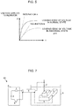
- FIG. 7 is a schematic configuration diagram of a conventional wire electrical discharge machine.
- a wire electrical discharge machine 10 performs electrical discharge machining by applying a voltage from a machining power supply 6 to a wire electrode 2 and a workpiece 4 on a table 3 through a feeder 5, in a machining tank 1.
- the machining power supply 6 comprises a resistive element 7, switching element 8, and DC power supply 9.
- the feeder 5 is connected to the wire electrode 2 and the table 3 in the machining tank 1 and immersed in a working fluid, so that it may be deteriorated or broken by aging due to corrosion or the like. If the feeder 5 is deteriorated or broken, the machining gap between the wire electrode 2 and the workpiece 4 cannot be normally charged with energy, resulting in a reduction in the machining speed and a false result of machining. Thus, it is important to detect the deterioration or breakage at an early stage.
- the object of the present invention is to provide a wire electrical discharge machine capable of detecting a deteriorated state of a feeder at an early stage.
- a wire electrical discharge machine is configured to perform removal machining of a workpiece by applying a voltage to a machining gap between a wire electrode and the workpiece through a feeder to generate electrical discharge and comprises a feeder deterioration detection unit configured to detect deterioration of the feeder.
- the feeder deterioration detection unit configured to detect deterioration of the feeder may comprise a storage unit in which a data table loaded with a current value for each electrical discharge is stored, a machining current detection unit configured to detect a machining current value during the machining, and a discharge frequency detection unit configured to detect the number of electrical discharges during the machining. And the deterioration of the feeder may be detected based on the result of comparison between the machining current value detected by the machining current detection unit and the product of the number of electrical discharges detected by the discharge frequency detection unit and the current value for each electrical discharge loaded in the data table.
- the feeder deterioration detection unit configured to detect deterioration of the feeder may comprise a resistance voltage detection unit configured to detect an inclination of a voltage applied to a resistor connected in series with the machining gap and the feeder, and a storage unit in which a data table preloaded with a reference value for the inclination of the voltage applied to the resistor is stored. And the deterioration of the feeder may be detected if the inclination of the voltage applied to the resistor, which is detected by the resistance voltage detection unit when the voltage is applied with the machining gap short-circuited, is smaller than the reference value loaded in the data table.
- the wire electrical discharge machine may be configured to issue a warning if the deterioration of the feeder is detected by the feeder deterioration detection unit.
- deterioration of a feeder can be detected to prevent production of defective workpieces.
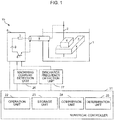
- FIG. 1 is a schematic configuration diagram of a wire electrical discharge machine according to a first embodiment of the present invention.
- a wire electrical discharge machine 10 of the present embodiment is an equivalent of the prior art wire electrical discharge machine 10 shown in FIG. 7 to which a numerical controller 21, machining current detection unit 26, and discharge frequency detection unit 27 are added.
- the numerical controller 21 comprises an operation unit 22, storage unit 23, comparison unit 24, and determination unit 25.
- the numerical controller 21, machining current detection unit 26, and discharge frequency detection unit 27 constitute a feeder deterioration detection unit.
- the wire electrical discharge machine 10 of the present embodiment performs electrical discharge machining by applying a voltage from a machining power supply 6 to a wire electrode 2 and a workpiece 4 on a table 3 through a feeder 5, in a machining tank 1.
- the machining power supply 6 comprises a resistive element 7, switching element 8, and DC power supply 9.
- the machining current detection unit 26 detects an average machining current I, which is an average of machining currents output from the machining power supply 6 during the electrical discharge machining.
- the discharge frequency detection unit 27 detects a discharge frequency N, which is the number of electrical discharges generated in a machining gap between the wire electrode 2 and the workpiece 4 during the electrical discharge machining, based on the change of the voltage output from the machining power supply 6.
- the detection of the average machining current I by the machining current detection unit 26 and the detection of the discharge frequency N by the discharge frequency detection unit 27 are performed during a predetermined time t1, and the result of the detection is output to the numerical controller 21.
- a data table is loaded with data obtained by associating machining conditions with a reference current Is as a current value for each electrical discharge during machining under those machining conditions.
- the comparison unit 24 performs comparison using the following expression (2), based on the current integral value I t1 calculated by the operation unit 22, the discharge frequency N detected by the discharge frequency detection unit 27, and the reference current I S corresponding to the machining conditions at the time of detection of the values loaded in the data table stored in the storage unit 23.
- a in expression (2) is a value of margin provided to the range of determination, to which about 10 percent of the product of the discharge frequency N and the reference current Is is given.
- the determination unit 25 determines that the feeder 5 is not abnormal if expression (2) holds so that the machining current (current integral value I t1 ) is determined to be substantially equal to the product of the discharge frequency N and the reference current Is. Moreover, if expression (2) does not holds so that the machining current (current integral value I t1 ) is determined to be deviated from the product of the discharge frequency N and the reference current Is, the resistance and inductance values of the feeder 5 can be assumed to be increased. Therefore, the feeder 5 is determined to be abnormal and a warning to this effect is issued.
- the numerical controller 21 repeatedly performs processing for the above-described determination during the machining.
- FIG. 2 is a flowchart showing a flow of processing performed by the wire electrical discharge machine of FIG. 1 . The description will be given in line with each step of the flowchart.
- Step SA01 The numerical controller 21 controls the machining current detection unit 26 and the discharge frequency detection unit 27 to start measuring the average machining current I and the discharge frequency N.
- Step SA02 The numerical controller 21 determines whether or not the predetermined time t1 has elapsed since the start of the measurement. If it is determined that the predetermined time t1 has elapsed, the processing proceeds to Step SA03. If not, the measurement of the average machining current I and the discharge frequency N is repeated.
- Step SA03 Based on the results of the arithmetic processing by the operation unit 22 and the comparison processing by the comparison unit 24, the determination unit 25 determines whether or not the integral value of the current I during the machining falls within the range of N ⁇ I S ⁇ A (where N is discharge frequency, Is is reference current, and A is a margin). If the integral value falls within the range of N ⁇ I S ⁇ A, it is determined that there is no abnormality, whereupon the processing proceeds to Step SA01 for the next measurement. If not, it is determined that there is abnormality, whereupon the processing proceeds to Step SA04.
- Step SA04 The determination unit 25 determines that the feeder 5 is deteriorated or broken.
- Step SA05 The determination unit 25 displays a warning to the effect that the feeder 5 is abnormal on a display device of the numerical controller 21.
- the warning may be notified by a sound or lamp.
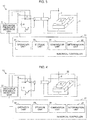
- FIG. 3 is a schematic configuration diagram of a wire electrical discharge machine according to a second embodiment of the present invention.
- a wire electrical discharge machine 10 of the present embodiment is an equivalent of the prior art wire electrical discharge machine 10 shown in FIG. 7 to which a numerical controller 21 and a resistance voltage detection unit 31 are added.
- the numerical controller 21 comprises an operation unit 22, storage unit 23, comparison unit 24, and determination unit 25.
- the numerical controller 21 and the resistance voltage detection unit 31 constitute a feeder deterioration detection unit.
- the wire electrical discharge machine 10 of the present embodiment performs electrical discharge machining by applying a voltage from a machining power supply 6 to a wire electrode 2 and a workpiece 4 on a table 3 through a feeder 5, in a machining tank 1.
- the machining power supply 6 comprises a resistive element 7, switching element 8, and DC power supply 9.
- the resistance voltage detection unit 31 detects the value of a voltage applied to the resistive element 7 that is connected in series with a system comprising the DC power supply 9, the feeder 5, and a machining gap.
- the numerical controller 21 of the present embodiment first performs control for short-circuiting the machining gap when detection processing for the state of deterioration of the feeder 5 is started.
- Methods for short-circuiting the machining gap include a method in which the wire electrode 2 and the workpiece 4 are brought into contact with each other and a method in which a relay 32 is provided between the wire electrode 2 and the table 3 so that the machining gap can be short-circuited by closing the relay 32, as shown in FIG. 4 .
- the numerical controller 21 controls the machining power supply 6 to apply a voltage to the machining gap after the machining gap is short-circuited and controls the resistance voltage detection unit 31 to detect the leading edge of the value of the voltage applied to the resistive element 7 that is connected in series with the system comprising the DC power supply 9, feeder 5, and machining gap.
- the graph of FIG. 5 shows the leading edge of the voltage applied to the resistive element 7.
- a reference value a is stored as an inclination value of the leading edge of the voltage applied to the resistive element 7 when the machining gap is short-circuited with the feeder 5 in a normal state.
- the operation unit 22 calculates the inclination of the leading edge of the voltage detected by the resistance voltage detection unit 31.
- the comparison unit 24 compares the inclination of the leading edge of the voltage detected by the resistance voltage detection unit 31, calculated by the operation unit 22, with the reference value a stored in the storage unit 23. If the result of the comparison by the comparison unit 24 indicates that the inclination of the leading edge of the voltage detected by the resistance voltage detection unit 31 is smaller than the reference value a, the resistance and inductance values of the feeder 5 can be considered to have been increased. Therefore, the determination unit 25 determines that the feeder 5 is abnormal and issues a warning to this effect.
- FIG. 6 is a flowchart showing a flow of processing performed by the wire electrical discharge machine of FIG. 3 (and FIG. 4 ). The description will be given in line with each step of the flowchart.
- Step SB01 The numerical controller 21 controls the wire electrical discharge machine 10 to short-circuit the machining gap between wire electrode 2 and the workpiece 4.
- Step SB02 The numerical controller 21 determines whether or not the machining gap is short-circuited. If the machining gap is short-circuited, the processing proceeds to Step SB03. If not, this step is repeated until the machining gap is short-circuited.
- Step SB03 The numerical controller 21 controls the machining power supply 6 to apply a voltage to the machining gap and controls the resistance voltage detection unit 31 to detect the leading edge of the voltage applied to the resistive element 7.
- Step SB04 Based on the inclination of the leading edge of the voltage applied to the resistive element 7, which is calculated by the operation unit 22 and detected in Step SB03, and the result of the comparison by the comparison unit 24 based on the reference value a stored in the storage unit 23, the determination unit 25 determines whether or not the inclination of the leading edge of the voltage applied to the resistive element 7 is smaller than the reference value. If the inclination is not smaller than the reference value, it is determined that there is no abnormality, whereupon this processing ends. If the inclination is smaller than the reference value, it is determined that there is abnormality, whereupon the processing proceeds to Step SB05.
- Step SB05 The determination unit 25 determines that the feeder 5 is deteriorated or broken.
- Step SB06 The determination unit 25 displays a warning to the effect that the feeder 5 is abnormal on a display device of the numerical controller 21 or the like.
- the warning may be notified by a sound or lamp.
Landscapes
- Engineering & Computer Science (AREA)
- Mechanical Engineering (AREA)
- Chemical & Material Sciences (AREA)
- Chemical Kinetics & Catalysis (AREA)
- Electrochemistry (AREA)
- Electrical Discharge Machining, Electrochemical Machining, And Combined Machining (AREA)
- Numerical Control (AREA)
Abstract
Description
- The present invention relates to a wire electrical discharge machine capable of detecting deterioration of a feeder.
- In a wire electrical discharge machine for wire electrical discharge machining, as described in Japanese Patent Application Laid-Open No.
2010-52092 -
FIG. 7 is a schematic configuration diagram of a conventional wire electrical discharge machine. - A wire
electrical discharge machine 10 performs electrical discharge machining by applying a voltage from amachining power supply 6 to awire electrode 2 and aworkpiece 4 on a table 3 through afeeder 5, in amachining tank 1. Themachining power supply 6 comprises aresistive element 7,switching element 8, andDC power supply 9. - In the wire
electrical discharge machine 10, as shown inFIG. 7 , thefeeder 5 is connected to thewire electrode 2 and the table 3 in themachining tank 1 and immersed in a working fluid, so that it may be deteriorated or broken by aging due to corrosion or the like. If thefeeder 5 is deteriorated or broken, the machining gap between thewire electrode 2 and theworkpiece 4 cannot be normally charged with energy, resulting in a reduction in the machining speed and a false result of machining. Thus, it is important to detect the deterioration or breakage at an early stage. - Accordingly, the object of the present invention is to provide a wire electrical discharge machine capable of detecting a deteriorated state of a feeder at an early stage.
- A wire electrical discharge machine according to the present invention is configured to perform removal machining of a workpiece by applying a voltage to a machining gap between a wire electrode and the workpiece through a feeder to generate electrical discharge and comprises a feeder deterioration detection unit configured to detect deterioration of the feeder.
- The feeder deterioration detection unit configured to detect deterioration of the feeder may comprise a storage unit in which a data table loaded with a current value for each electrical discharge is stored, a machining current detection unit configured to detect a machining current value during the machining, and a discharge frequency detection unit configured to detect the number of electrical discharges during the machining. And the deterioration of the feeder may be detected based on the result of comparison between the machining current value detected by the machining current detection unit and the product of the number of electrical discharges detected by the discharge frequency detection unit and the current value for each electrical discharge loaded in the data table.
- The feeder deterioration detection unit configured to detect deterioration of the feeder may comprise a resistance voltage detection unit configured to detect an inclination of a voltage applied to a resistor connected in series with the machining gap and the feeder, and a storage unit in which a data table preloaded with a reference value for the inclination of the voltage applied to the resistor is stored. And the deterioration of the feeder may be detected if the inclination of the voltage applied to the resistor, which is detected by the resistance voltage detection unit when the voltage is applied with the machining gap short-circuited, is smaller than the reference value loaded in the data table.
- The wire electrical discharge machine may be configured to issue a warning if the deterioration of the feeder is detected by the feeder deterioration detection unit.
- According to the present invention, deterioration of a feeder can be detected to prevent production of defective workpieces.
- The above and other objects and features of the present invention will be obvious from the ensuing description of embodiments with reference to the accompanying drawings, in which:
-
FIG. 1 is a schematic configuration diagram of a wire electrical discharge machine according to a first embodiment of the present invention; -
FIG. 2 is a flowchart showing a flow of processing performed by the wire electrical discharge machine ofFIG. 1 ; -
FIG. 3 is a schematic configuration diagram of a wire electrical discharge machine according to a second embodiment of the present invention; -
FIG. 4 is a schematic configuration diagram showing a case in which a relay is used as a short-circuiting means for a machining gap in the wire electrical discharge machine ofFIG. 3 ; -
FIG. 5 is a graph showing the leading edge of a voltage applied to a resistive element in the wire electrical discharge machine ofFIG. 4 ; -
FIG. 6 is a flowchart showing a flow of processing performed by the wire electrical discharge machine ofFIG. 3 (and FIG. 4 ); and -
FIG. 7 is a schematic configuration diagram of a conventional wire electrical discharge machine. - Embodiments of the present invention will now be described with reference to the accompanying drawings. The same reference numerals are used to designate those components which are identical or similar to their conventional counterparts.
-
FIG. 1 is a schematic configuration diagram of a wire electrical discharge machine according to a first embodiment of the present invention. - A wire
electrical discharge machine 10 of the present embodiment is an equivalent of the prior art wireelectrical discharge machine 10 shown inFIG. 7 to which anumerical controller 21, machiningcurrent detection unit 26, and dischargefrequency detection unit 27 are added. Thenumerical controller 21 comprises anoperation unit 22,storage unit 23,comparison unit 24, anddetermination unit 25. In the present embodiment, thenumerical controller 21, machiningcurrent detection unit 26, and dischargefrequency detection unit 27 constitute a feeder deterioration detection unit. - The wire
electrical discharge machine 10 of the present embodiment, like the conventional one, performs electrical discharge machining by applying a voltage from amachining power supply 6 to awire electrode 2 and aworkpiece 4 on a table 3 through afeeder 5, in amachining tank 1. Themachining power supply 6 comprises aresistive element 7,switching element 8, andDC power supply 9. - The machining
current detection unit 26 detects an average machining current I, which is an average of machining currents output from themachining power supply 6 during the electrical discharge machining. The dischargefrequency detection unit 27 detects a discharge frequency N, which is the number of electrical discharges generated in a machining gap between thewire electrode 2 and theworkpiece 4 during the electrical discharge machining, based on the change of the voltage output from themachining power supply 6. The detection of the average machining current I by the machiningcurrent detection unit 26 and the detection of the discharge frequency N by the dischargefrequency detection unit 27 are performed during a predetermined time t1, and the result of the detection is output to thenumerical controller 21. - In the
storage unit 23 of thenumerical controller 21, a data table is loaded with data obtained by associating machining conditions with a reference current Is as a current value for each electrical discharge during machining under those machining conditions. Theoperation unit 22 calculates an integral value It1 of a current having flowed through thefeeder 5 during the predetermined time t1, based on the average machining current I detected during the predetermined time t1 by the machiningcurrent detection unit 26, by expression (1) as follows:
- The
comparison unit 24 performs comparison using the following expression (2), based on the current integral value It1 calculated by theoperation unit 22, the discharge frequency N detected by the dischargefrequency detection unit 27, and the reference current IS corresponding to the machining conditions at the time of detection of the values loaded in the data table stored in thestorage unit 23. Note that A in expression (2) is a value of margin provided to the range of determination, to which about 10 percent of the product of the discharge frequency N and the reference current Is is given.
- The
determination unit 25 determines that thefeeder 5 is not abnormal if expression (2) holds so that the machining current (current integral value It1) is determined to be substantially equal to the product of the discharge frequency N and the reference current Is. Moreover, if expression (2) does not holds so that the machining current (current integral value It1) is determined to be deviated from the product of the discharge frequency N and the reference current Is, the resistance and inductance values of thefeeder 5 can be assumed to be increased. Therefore, thefeeder 5 is determined to be abnormal and a warning to this effect is issued. - The
numerical controller 21 repeatedly performs processing for the above-described determination during the machining. -
FIG. 2 is a flowchart showing a flow of processing performed by the wire electrical discharge machine ofFIG. 1 . The description will be given in line with each step of the flowchart. - [Step SA01] The
numerical controller 21 controls the machiningcurrent detection unit 26 and the dischargefrequency detection unit 27 to start measuring the average machining current I and the discharge frequency N. - [Step SA02] The
numerical controller 21 determines whether or not the predetermined time t1 has elapsed since the start of the measurement. If it is determined that the predetermined time t1 has elapsed, the processing proceeds to Step SA03. If not, the measurement of the average machining current I and the discharge frequency N is repeated. - [Step SA03] Based on the results of the arithmetic processing by the
operation unit 22 and the comparison processing by thecomparison unit 24, thedetermination unit 25 determines whether or not the integral value of the current I during the machining falls within the range of N×IS ± A (where N is discharge frequency, Is is reference current, and A is a margin). If the integral value falls within the range of N×IS ± A, it is determined that there is no abnormality, whereupon the processing proceeds to Step SA01 for the next measurement. If not, it is determined that there is abnormality, whereupon the processing proceeds to Step SA04. - [Step SA04] The
determination unit 25 determines that thefeeder 5 is deteriorated or broken. - [Step SA05] The
determination unit 25 displays a warning to the effect that thefeeder 5 is abnormal on a display device of thenumerical controller 21. The warning may be notified by a sound or lamp. -
FIG. 3 is a schematic configuration diagram of a wire electrical discharge machine according to a second embodiment of the present invention. - A wire
electrical discharge machine 10 of the present embodiment is an equivalent of the prior art wireelectrical discharge machine 10 shown inFIG. 7 to which anumerical controller 21 and a resistancevoltage detection unit 31 are added. Thenumerical controller 21 comprises anoperation unit 22,storage unit 23,comparison unit 24, anddetermination unit 25. In the present embodiment, thenumerical controller 21 and the resistancevoltage detection unit 31 constitute a feeder deterioration detection unit. - The wire
electrical discharge machine 10 of the present embodiment, like the conventional one, performs electrical discharge machining by applying a voltage from amachining power supply 6 to awire electrode 2 and aworkpiece 4 on a table 3 through afeeder 5, in amachining tank 1. Themachining power supply 6 comprises aresistive element 7, switchingelement 8, andDC power supply 9. - The resistance
voltage detection unit 31 detects the value of a voltage applied to theresistive element 7 that is connected in series with a system comprising theDC power supply 9, thefeeder 5, and a machining gap. - The
numerical controller 21 of the present embodiment first performs control for short-circuiting the machining gap when detection processing for the state of deterioration of thefeeder 5 is started. Methods for short-circuiting the machining gap include a method in which thewire electrode 2 and theworkpiece 4 are brought into contact with each other and a method in which arelay 32 is provided between thewire electrode 2 and the table 3 so that the machining gap can be short-circuited by closing therelay 32, as shown inFIG. 4 . - The
numerical controller 21 controls themachining power supply 6 to apply a voltage to the machining gap after the machining gap is short-circuited and controls the resistancevoltage detection unit 31 to detect the leading edge of the value of the voltage applied to theresistive element 7 that is connected in series with the system comprising theDC power supply 9,feeder 5, and machining gap. The graph ofFIG. 5 shows the leading edge of the voltage applied to theresistive element 7. - In the
storage unit 23 of thenumerical controller 21 of the present embodiment, a reference value a is stored as an inclination value of the leading edge of the voltage applied to theresistive element 7 when the machining gap is short-circuited with thefeeder 5 in a normal state. - The
operation unit 22 calculates the inclination of the leading edge of the voltage detected by the resistancevoltage detection unit 31. Moreover, thecomparison unit 24 compares the inclination of the leading edge of the voltage detected by the resistancevoltage detection unit 31, calculated by theoperation unit 22, with the reference value a stored in thestorage unit 23. If the result of the comparison by thecomparison unit 24 indicates that the inclination of the leading edge of the voltage detected by the resistancevoltage detection unit 31 is smaller than the reference value a, the resistance and inductance values of thefeeder 5 can be considered to have been increased. Therefore, thedetermination unit 25 determines that thefeeder 5 is abnormal and issues a warning to this effect. -
FIG. 6 is a flowchart showing a flow of processing performed by the wire electrical discharge machine ofFIG. 3 (and FIG. 4 ). The description will be given in line with each step of the flowchart. - [Step SB01] The
numerical controller 21 controls the wireelectrical discharge machine 10 to short-circuit the machining gap betweenwire electrode 2 and theworkpiece 4. - [Step SB02] The
numerical controller 21 determines whether or not the machining gap is short-circuited. If the machining gap is short-circuited, the processing proceeds to Step SB03. If not, this step is repeated until the machining gap is short-circuited. - [Step SB03] The
numerical controller 21 controls themachining power supply 6 to apply a voltage to the machining gap and controls the resistancevoltage detection unit 31 to detect the leading edge of the voltage applied to theresistive element 7. - [Step SB04] Based on the inclination of the leading edge of the voltage applied to the
resistive element 7, which is calculated by theoperation unit 22 and detected in Step SB03, and the result of the comparison by thecomparison unit 24 based on the reference value a stored in thestorage unit 23, thedetermination unit 25 determines whether or not the inclination of the leading edge of the voltage applied to theresistive element 7 is smaller than the reference value. If the inclination is not smaller than the reference value, it is determined that there is no abnormality, whereupon this processing ends. If the inclination is smaller than the reference value, it is determined that there is abnormality, whereupon the processing proceeds to Step SB05. - [Step SB05] The
determination unit 25 determines that thefeeder 5 is deteriorated or broken. - [Step SB06] The
determination unit 25 displays a warning to the effect that thefeeder 5 is abnormal on a display device of thenumerical controller 21 or the like. The warning may be notified by a sound or lamp. - While embodiments of the present invention have been described herein, the invention is not limited to the above-described embodiments and may be suitably modified and embodied in various forms.
Claims (4)
- A wire electrical discharge machine which performs removal machining of a workpiece by applying a voltage to a machining gap between a wire electrode and the workpiece through a feeder to generate electrical discharge, the wire electrical discharge machine comprising:a feeder deterioration detection unit configured to detect deterioration of the feeder.
- The wire electrical discharge machine according to claim 1, wherein the feeder deterioration detection unit configured to detect deterioration of the feeder comprises:a storage unit in which a data table loaded with a current value for each electrical discharge is stored;a machining current detection unit configured to detect a machining current value during the machining; anda discharge frequency detection unit configured to detect the number of electrical discharges during the machining, whereinthe deterioration of the feeder is detected based on the result of comparison between the machining current value detected by the machining current detection unit and the product of the number of electrical discharges detected by the discharge frequency detection unit and the current value for each electrical discharge loaded in the data table.
- The wire electrical discharge machine according to claim 1, wherein the feeder deterioration detection unit configured to detect deterioration of the feeder comprises:a resistance voltage detection unit configured to detect an inclination of a voltage applied to a resistor connected in series with the machining gap and the feeder, anda storage unit in which a data table preloaded with a reference value for the inclination of the voltage applied to the resistor is stored, whereinthe deterioration of the feeder is detected if the inclination of the voltage applied to the resistor, which is detected by the resistance voltage detection unit when the voltage is applied with the machining gap short-circuited, is smaller than the reference value loaded in the data table.
- The wire electrical discharge machine according to any one of claims 1 to 3, wherein a warning is issued if the deterioration of the feeder is detected by the feeder deterioration detection unit.
Applications Claiming Priority (1)
| Application Number | Priority Date | Filing Date | Title |
|---|---|---|---|
| JP2016001583A JP6348131B2 (en) | 2016-01-07 | 2016-01-07 | Wire electric discharge machine with function to detect deterioration of power supply line |
Publications (2)
| Publication Number | Publication Date |
|---|---|
| EP3189919A1 true EP3189919A1 (en) | 2017-07-12 |
| EP3189919B1 EP3189919B1 (en) | 2021-12-15 |
Family
ID=57614268
Family Applications (1)
| Application Number | Title | Priority Date | Filing Date |
|---|---|---|---|
| EP16207076.7A Active EP3189919B1 (en) | 2016-01-07 | 2016-12-28 | Method for detecting the deterioration of the power cable of a wire electrical discharge machine |
Country Status (5)
| Country | Link |
|---|---|
| US (1) | US10751820B2 (en) |
| EP (1) | EP3189919B1 (en) |
| JP (1) | JP6348131B2 (en) |
| KR (1) | KR101970391B1 (en) |
| CN (1) | CN106944687B (en) |
Families Citing this family (1)
| Publication number | Priority date | Publication date | Assignee | Title |
|---|---|---|---|---|
| WO2022038761A1 (en) * | 2020-08-21 | 2022-02-24 | 三菱電機株式会社 | Processing report creation device and wire electric discharge machine |
Citations (3)
| Publication number | Priority date | Publication date | Assignee | Title |
|---|---|---|---|---|
| JPH1069989A (en) * | 1996-08-27 | 1998-03-10 | Matsushita Electric Works Ltd | Discharge lamp lighting device |
| US20090287426A1 (en) * | 2008-01-11 | 2009-11-19 | Kukowski Thomas R | Elastomeric conductor and shield fault detection |
| EP2158993A2 (en) * | 2008-08-28 | 2010-03-03 | Fanuc Ltd | Wire electric discharge machine having function of detecting detachment/attachment of an electrode pin |
Family Cites Families (17)
| Publication number | Priority date | Publication date | Assignee | Title |
|---|---|---|---|---|
| US4892989A (en) * | 1983-05-02 | 1990-01-09 | Mitsubishi Denki Kabushiki Kaisha | Discharge machining apparatus having means for distinguishing abnormal interelectrode gap conditions |
| JPH02131821A (en) * | 1988-11-04 | 1990-05-21 | Fanuc Ltd | Wire electric discharge machine with status display |
| JP2722867B2 (en) * | 1991-07-01 | 1998-03-09 | 三菱電機株式会社 | Wire electric discharge machine |
| JPH0512044A (en) | 1991-07-03 | 1993-01-22 | Toshiba Corp | Processing system |
| JP2554878Y2 (en) | 1991-07-30 | 1997-11-19 | 西部電機株式会社 | Wire electric discharge machine |
| JPH05200627A (en) * | 1992-01-22 | 1993-08-10 | Brother Ind Ltd | Breakage prevention device for wire electric discharge machine |
| JPH05305520A (en) * | 1992-04-30 | 1993-11-19 | Brother Ind Ltd | Wire electric discharge machine |
| JPH0691433A (en) * | 1992-09-11 | 1994-04-05 | Fanuc Ltd | Wire-cut electric discharge machine |
| JPH07178622A (en) * | 1993-12-22 | 1995-07-18 | Fanuc Ltd | Wire monitor for wire cut electric discharge machine |
| US20090120911A1 (en) * | 2007-11-12 | 2009-05-14 | Fanuc Ltd | Wire break detecting device for wire electric discharge machine |
| WO2009098764A1 (en) * | 2008-02-06 | 2009-08-13 | Mitsubishi Electric Corporation | Power control device for electric discharge machine |
| DE112011105416T8 (en) | 2011-07-06 | 2014-06-18 | Mitsubishi Electric Corporation | Electric wire EDM processing device |
| US8519295B2 (en) * | 2011-12-02 | 2013-08-27 | Mitsubishi Electric Corporation | Controller of electrical discharge machine |
| WO2013108530A1 (en) * | 2012-01-18 | 2013-07-25 | 三菱電機株式会社 | Wire discharge machining device, wire discharge machining method, thin-plate manufacturing method, and semiconductor wafer manufacturing method |
| JP5204321B1 (en) * | 2012-02-01 | 2013-06-05 | ファナック株式会社 | Wire electrical discharge machine that detects the machining state and calculates the average voltage between the electrodes |
| JP6311725B2 (en) * | 2013-02-04 | 2018-04-18 | アンカ・ピーティーワイ・リミテッド | Pulse and gap control for electrical discharge machining equipment |
| JP6147599B2 (en) * | 2013-07-23 | 2017-06-14 | 株式会社日本製鋼所 | Degradation / disconnection detection method for feeder lines |
-
2016
- 2016-01-07 JP JP2016001583A patent/JP6348131B2/en active Active
- 2016-12-28 EP EP16207076.7A patent/EP3189919B1/en active Active
- 2016-12-30 US US15/394,943 patent/US10751820B2/en active Active
-
2017
- 2017-01-05 KR KR1020170001798A patent/KR101970391B1/en active Active
- 2017-01-06 CN CN201710010096.3A patent/CN106944687B/en active Active
Patent Citations (4)
| Publication number | Priority date | Publication date | Assignee | Title |
|---|---|---|---|---|
| JPH1069989A (en) * | 1996-08-27 | 1998-03-10 | Matsushita Electric Works Ltd | Discharge lamp lighting device |
| US20090287426A1 (en) * | 2008-01-11 | 2009-11-19 | Kukowski Thomas R | Elastomeric conductor and shield fault detection |
| EP2158993A2 (en) * | 2008-08-28 | 2010-03-03 | Fanuc Ltd | Wire electric discharge machine having function of detecting detachment/attachment of an electrode pin |
| JP2010052092A (en) | 2008-08-28 | 2010-03-11 | Fanuc Ltd | Wire electric discharging machine having function of detecting detachment/attachment of electrode pin |
Also Published As
| Publication number | Publication date |
|---|---|
| US20170197267A1 (en) | 2017-07-13 |
| JP2017121682A (en) | 2017-07-13 |
| US10751820B2 (en) | 2020-08-25 |
| JP6348131B2 (en) | 2018-06-27 |
| EP3189919B1 (en) | 2021-12-15 |
| KR101970391B1 (en) | 2019-04-18 |
| KR20170082988A (en) | 2017-07-17 |
| CN106944687B (en) | 2019-03-01 |
| CN106944687A (en) | 2017-07-14 |
Similar Documents
| Publication | Publication Date | Title |
|---|---|---|
| EP2623245A2 (en) | Wire electric discharge machine capable of detecting machining state and determining average voltage in machining gap | |
| US20130024020A1 (en) | Numerical control device, wire electric discharge machining apparatus using the same, and wire electric discharge machining method using the same | |
| JP4444303B2 (en) | Discharge occurrence detection method and apparatus | |
| KR101879026B1 (en) | A wire electric discharge machine with tension monitoring function | |
| EP1806196A1 (en) | Electric discharge machining power supply apparatus, and electric discharge machining method | |
| EP2985105B1 (en) | Wire electric discharge machine determining whether or not electrical discharge machining of workpiece can be perfomed | |
| EP3189919B1 (en) | Method for detecting the deterioration of the power cable of a wire electrical discharge machine | |
| US10493547B2 (en) | Wire electrical discharge machining device | |
| EP1918054A1 (en) | Method and device for electrical discharge machining | |
| SU820650A3 (en) | Method of electroerosion treatment | |
| US3597570A (en) | Device for detecting sustained arcing across electrospark machining gaps | |
| CN116352196B (en) | Wire electric discharge machine and wire electric discharge machining method | |
| KR920009493A (en) | Adaptive Control Device and Method of EDM | |
| EP3643440B1 (en) | Wire electrical discharge machine and electrical discharge machining method | |
| US4551809A (en) | Apparatus and method for monitoring the machining conditions of an EDM apparatus | |
| JPH0777695B2 (en) | Method and apparatus for detecting and controlling low level electric discharge in electric discharge machining | |
| JPS63318210A (en) | Control device for electric discharge machine | |
| JP2017061023A (en) | Machining power supply of wire electric discharge machine | |
| US11752565B2 (en) | Power source device for electric discharge machine | |
| EP1410865A2 (en) | Electric discharge apparatus | |
| CN104162723B (en) | There is the wire electric discharge machine of antirust function | |
| JP2005094915A (en) | Charging and discharging equipment | |
| JPS63185524A (en) | Electric discharge machining device | |
| JPS61125726A (en) | Electric discharge machine | |
| JPS614621A (en) | Voltage applying method and its device in electric discharge machining |
Legal Events
| Date | Code | Title | Description |
|---|---|---|---|
| PUAI | Public reference made under article 153(3) epc to a published international application that has entered the european phase |
Free format text: ORIGINAL CODE: 0009012 |
|
| STAA | Information on the status of an ep patent application or granted ep patent |
Free format text: STATUS: THE APPLICATION HAS BEEN PUBLISHED |
|
| AK | Designated contracting states |
Kind code of ref document: A1 Designated state(s): AL AT BE BG CH CY CZ DE DK EE ES FI FR GB GR HR HU IE IS IT LI LT LU LV MC MK MT NL NO PL PT RO RS SE SI SK SM TR |
|
| AX | Request for extension of the european patent |
Extension state: BA ME |
|
| STAA | Information on the status of an ep patent application or granted ep patent |
Free format text: STATUS: REQUEST FOR EXAMINATION WAS MADE |
|
| 17P | Request for examination filed |
Effective date: 20171121 |
|
| RBV | Designated contracting states (corrected) |
Designated state(s): AL AT BE BG CH CY CZ DE DK EE ES FI FR GB GR HR HU IE IS IT LI LT LU LV MC MK MT NL NO PL PT RO RS SE SI SK SM TR |
|
| STAA | Information on the status of an ep patent application or granted ep patent |
Free format text: STATUS: EXAMINATION IS IN PROGRESS |
|
| 17Q | First examination report despatched |
Effective date: 20200512 |
|
| RIC1 | Information provided on ipc code assigned before grant |
Ipc: B23H 1/02 20060101AFI20210607BHEP Ipc: B23H 7/04 20060101ALI20210607BHEP Ipc: G01R 21/00 20060101ALI20210607BHEP Ipc: B23H 11/00 20060101ALN20210607BHEP |
|
| GRAP | Despatch of communication of intention to grant a patent |
Free format text: ORIGINAL CODE: EPIDOSNIGR1 |
|
| STAA | Information on the status of an ep patent application or granted ep patent |
Free format text: STATUS: GRANT OF PATENT IS INTENDED |
|
| RIC1 | Information provided on ipc code assigned before grant |
Ipc: B23H 1/02 20060101AFI20210628BHEP Ipc: B23H 7/04 20060101ALI20210628BHEP Ipc: G01R 21/00 20060101ALI20210628BHEP Ipc: B23H 11/00 20060101ALN20210628BHEP |
|
| INTG | Intention to grant announced |
Effective date: 20210803 |
|
| GRAS | Grant fee paid |
Free format text: ORIGINAL CODE: EPIDOSNIGR3 |
|
| GRAA | (expected) grant |
Free format text: ORIGINAL CODE: 0009210 |
|
| STAA | Information on the status of an ep patent application or granted ep patent |
Free format text: STATUS: THE PATENT HAS BEEN GRANTED |
|
| AK | Designated contracting states |
Kind code of ref document: B1 Designated state(s): AL AT BE BG CH CY CZ DE DK EE ES FI FR GB GR HR HU IE IS IT LI LT LU LV MC MK MT NL NO PL PT RO RS SE SI SK SM TR |
|
| REG | Reference to a national code |
Ref country code: GB Ref legal event code: FG4D Ref country code: CH Ref legal event code: EP |
|
| REG | Reference to a national code |
Ref country code: DE Ref legal event code: R096 Ref document number: 602016067331 Country of ref document: DE |
|
| REG | Reference to a national code |
Ref country code: IE Ref legal event code: FG4D |
|
| REG | Reference to a national code |
Ref country code: AT Ref legal event code: REF Ref document number: 1455112 Country of ref document: AT Kind code of ref document: T Effective date: 20220115 |
|
| REG | Reference to a national code |
Ref country code: LT Ref legal event code: MG9D |
|
| REG | Reference to a national code |
Ref country code: NL Ref legal event code: MP Effective date: 20211215 |
|
| PG25 | Lapsed in a contracting state [announced via postgrant information from national office to epo] |
Ref country code: RS Free format text: LAPSE BECAUSE OF FAILURE TO SUBMIT A TRANSLATION OF THE DESCRIPTION OR TO PAY THE FEE WITHIN THE PRESCRIBED TIME-LIMIT Effective date: 20211215 Ref country code: LT Free format text: LAPSE BECAUSE OF FAILURE TO SUBMIT A TRANSLATION OF THE DESCRIPTION OR TO PAY THE FEE WITHIN THE PRESCRIBED TIME-LIMIT Effective date: 20211215 Ref country code: FI Free format text: LAPSE BECAUSE OF FAILURE TO SUBMIT A TRANSLATION OF THE DESCRIPTION OR TO PAY THE FEE WITHIN THE PRESCRIBED TIME-LIMIT Effective date: 20211215 Ref country code: BG Free format text: LAPSE BECAUSE OF FAILURE TO SUBMIT A TRANSLATION OF THE DESCRIPTION OR TO PAY THE FEE WITHIN THE PRESCRIBED TIME-LIMIT Effective date: 20220315 |
|
| REG | Reference to a national code |
Ref country code: AT Ref legal event code: MK05 Ref document number: 1455112 Country of ref document: AT Kind code of ref document: T Effective date: 20211215 |
|
| PG25 | Lapsed in a contracting state [announced via postgrant information from national office to epo] |
Ref country code: SE Free format text: LAPSE BECAUSE OF FAILURE TO SUBMIT A TRANSLATION OF THE DESCRIPTION OR TO PAY THE FEE WITHIN THE PRESCRIBED TIME-LIMIT Effective date: 20211215 Ref country code: NO Free format text: LAPSE BECAUSE OF FAILURE TO SUBMIT A TRANSLATION OF THE DESCRIPTION OR TO PAY THE FEE WITHIN THE PRESCRIBED TIME-LIMIT Effective date: 20220315 Ref country code: LV Free format text: LAPSE BECAUSE OF FAILURE TO SUBMIT A TRANSLATION OF THE DESCRIPTION OR TO PAY THE FEE WITHIN THE PRESCRIBED TIME-LIMIT Effective date: 20211215 Ref country code: HR Free format text: LAPSE BECAUSE OF FAILURE TO SUBMIT A TRANSLATION OF THE DESCRIPTION OR TO PAY THE FEE WITHIN THE PRESCRIBED TIME-LIMIT Effective date: 20211215 Ref country code: GR Free format text: LAPSE BECAUSE OF FAILURE TO SUBMIT A TRANSLATION OF THE DESCRIPTION OR TO PAY THE FEE WITHIN THE PRESCRIBED TIME-LIMIT Effective date: 20220316 |
|
| PG25 | Lapsed in a contracting state [announced via postgrant information from national office to epo] |
Ref country code: NL Free format text: LAPSE BECAUSE OF FAILURE TO SUBMIT A TRANSLATION OF THE DESCRIPTION OR TO PAY THE FEE WITHIN THE PRESCRIBED TIME-LIMIT Effective date: 20211215 |
|
| PG25 | Lapsed in a contracting state [announced via postgrant information from national office to epo] |
Ref country code: SM Free format text: LAPSE BECAUSE OF FAILURE TO SUBMIT A TRANSLATION OF THE DESCRIPTION OR TO PAY THE FEE WITHIN THE PRESCRIBED TIME-LIMIT Effective date: 20211215 Ref country code: SK Free format text: LAPSE BECAUSE OF FAILURE TO SUBMIT A TRANSLATION OF THE DESCRIPTION OR TO PAY THE FEE WITHIN THE PRESCRIBED TIME-LIMIT Effective date: 20211215 Ref country code: RO Free format text: LAPSE BECAUSE OF FAILURE TO SUBMIT A TRANSLATION OF THE DESCRIPTION OR TO PAY THE FEE WITHIN THE PRESCRIBED TIME-LIMIT Effective date: 20211215 Ref country code: PT Free format text: LAPSE BECAUSE OF FAILURE TO SUBMIT A TRANSLATION OF THE DESCRIPTION OR TO PAY THE FEE WITHIN THE PRESCRIBED TIME-LIMIT Effective date: 20220418 Ref country code: ES Free format text: LAPSE BECAUSE OF FAILURE TO SUBMIT A TRANSLATION OF THE DESCRIPTION OR TO PAY THE FEE WITHIN THE PRESCRIBED TIME-LIMIT Effective date: 20211215 Ref country code: EE Free format text: LAPSE BECAUSE OF FAILURE TO SUBMIT A TRANSLATION OF THE DESCRIPTION OR TO PAY THE FEE WITHIN THE PRESCRIBED TIME-LIMIT Effective date: 20211215 Ref country code: CZ Free format text: LAPSE BECAUSE OF FAILURE TO SUBMIT A TRANSLATION OF THE DESCRIPTION OR TO PAY THE FEE WITHIN THE PRESCRIBED TIME-LIMIT Effective date: 20211215 |
|
| PG25 | Lapsed in a contracting state [announced via postgrant information from national office to epo] |
Ref country code: PL Free format text: LAPSE BECAUSE OF FAILURE TO SUBMIT A TRANSLATION OF THE DESCRIPTION OR TO PAY THE FEE WITHIN THE PRESCRIBED TIME-LIMIT Effective date: 20211215 Ref country code: AT Free format text: LAPSE BECAUSE OF FAILURE TO SUBMIT A TRANSLATION OF THE DESCRIPTION OR TO PAY THE FEE WITHIN THE PRESCRIBED TIME-LIMIT Effective date: 20211215 |
|
| REG | Reference to a national code |
Ref country code: DE Ref legal event code: R097 Ref document number: 602016067331 Country of ref document: DE |
|
| REG | Reference to a national code |
Ref country code: BE Ref legal event code: MM Effective date: 20211231 |
|
| PG25 | Lapsed in a contracting state [announced via postgrant information from national office to epo] |
Ref country code: MC Free format text: LAPSE BECAUSE OF FAILURE TO SUBMIT A TRANSLATION OF THE DESCRIPTION OR TO PAY THE FEE WITHIN THE PRESCRIBED TIME-LIMIT Effective date: 20211215 Ref country code: IS Free format text: LAPSE BECAUSE OF FAILURE TO SUBMIT A TRANSLATION OF THE DESCRIPTION OR TO PAY THE FEE WITHIN THE PRESCRIBED TIME-LIMIT Effective date: 20220415 |
|
| PLBE | No opposition filed within time limit |
Free format text: ORIGINAL CODE: 0009261 |
|
| STAA | Information on the status of an ep patent application or granted ep patent |
Free format text: STATUS: NO OPPOSITION FILED WITHIN TIME LIMIT |
|
| PG25 | Lapsed in a contracting state [announced via postgrant information from national office to epo] |
Ref country code: LU Free format text: LAPSE BECAUSE OF NON-PAYMENT OF DUE FEES Effective date: 20211228 Ref country code: IE Free format text: LAPSE BECAUSE OF NON-PAYMENT OF DUE FEES Effective date: 20211228 Ref country code: DK Free format text: LAPSE BECAUSE OF FAILURE TO SUBMIT A TRANSLATION OF THE DESCRIPTION OR TO PAY THE FEE WITHIN THE PRESCRIBED TIME-LIMIT Effective date: 20211215 Ref country code: AL Free format text: LAPSE BECAUSE OF FAILURE TO SUBMIT A TRANSLATION OF THE DESCRIPTION OR TO PAY THE FEE WITHIN THE PRESCRIBED TIME-LIMIT Effective date: 20211215 |
|
| 26N | No opposition filed |
Effective date: 20220916 |
|
| GBPC | Gb: european patent ceased through non-payment of renewal fee |
Effective date: 20220315 |
|
| PG25 | Lapsed in a contracting state [announced via postgrant information from national office to epo] |
Ref country code: SI Free format text: LAPSE BECAUSE OF FAILURE TO SUBMIT A TRANSLATION OF THE DESCRIPTION OR TO PAY THE FEE WITHIN THE PRESCRIBED TIME-LIMIT Effective date: 20211215 Ref country code: BE Free format text: LAPSE BECAUSE OF NON-PAYMENT OF DUE FEES Effective date: 20211231 |
|
| PG25 | Lapsed in a contracting state [announced via postgrant information from national office to epo] |
Ref country code: FR Free format text: LAPSE BECAUSE OF NON-PAYMENT OF DUE FEES Effective date: 20220215 |
|
| PG25 | Lapsed in a contracting state [announced via postgrant information from national office to epo] |
Ref country code: GB Free format text: LAPSE BECAUSE OF NON-PAYMENT OF DUE FEES Effective date: 20220315 |
|
| PG25 | Lapsed in a contracting state [announced via postgrant information from national office to epo] |
Ref country code: IT Free format text: LAPSE BECAUSE OF FAILURE TO SUBMIT A TRANSLATION OF THE DESCRIPTION OR TO PAY THE FEE WITHIN THE PRESCRIBED TIME-LIMIT Effective date: 20211215 Ref country code: HU Free format text: LAPSE BECAUSE OF FAILURE TO SUBMIT A TRANSLATION OF THE DESCRIPTION OR TO PAY THE FEE WITHIN THE PRESCRIBED TIME-LIMIT; INVALID AB INITIO Effective date: 20161228 |
|
| PG25 | Lapsed in a contracting state [announced via postgrant information from national office to epo] |
Ref country code: CY Free format text: LAPSE BECAUSE OF FAILURE TO SUBMIT A TRANSLATION OF THE DESCRIPTION OR TO PAY THE FEE WITHIN THE PRESCRIBED TIME-LIMIT Effective date: 20211215 |
|
| PG25 | Lapsed in a contracting state [announced via postgrant information from national office to epo] |
Ref country code: MK Free format text: LAPSE BECAUSE OF FAILURE TO SUBMIT A TRANSLATION OF THE DESCRIPTION OR TO PAY THE FEE WITHIN THE PRESCRIBED TIME-LIMIT Effective date: 20211215 |
|
| PG25 | Lapsed in a contracting state [announced via postgrant information from national office to epo] |
Ref country code: MT Free format text: LAPSE BECAUSE OF FAILURE TO SUBMIT A TRANSLATION OF THE DESCRIPTION OR TO PAY THE FEE WITHIN THE PRESCRIBED TIME-LIMIT Effective date: 20211215 |
|
| PG25 | Lapsed in a contracting state [announced via postgrant information from national office to epo] |
Ref country code: TR Free format text: LAPSE BECAUSE OF FAILURE TO SUBMIT A TRANSLATION OF THE DESCRIPTION OR TO PAY THE FEE WITHIN THE PRESCRIBED TIME-LIMIT Effective date: 20211215 |
|
| REG | Reference to a national code |
Ref country code: CH Ref legal event code: U11 Free format text: ST27 STATUS EVENT CODE: U-0-0-U10-U11 (AS PROVIDED BY THE NATIONAL OFFICE) Effective date: 20260101 |
|
| PGFP | Annual fee paid to national office [announced via postgrant information from national office to epo] |
Ref country code: DE Payment date: 20251126 Year of fee payment: 10 |
|
| PGFP | Annual fee paid to national office [announced via postgrant information from national office to epo] |
Ref country code: CH Payment date: 20260101 Year of fee payment: 10 |